JP5877125B2 - Corrosion suppression device, seawater desalination device and pump device provided with the same - Google Patents
Corrosion suppression device, seawater desalination device and pump device provided with the same Download PDFInfo
- Publication number
- JP5877125B2 JP5877125B2 JP2012120346A JP2012120346A JP5877125B2 JP 5877125 B2 JP5877125 B2 JP 5877125B2 JP 2012120346 A JP2012120346 A JP 2012120346A JP 2012120346 A JP2012120346 A JP 2012120346A JP 5877125 B2 JP5877125 B2 JP 5877125B2
- Authority
- JP
- Japan
- Prior art keywords
- anode
- corrosion
- seawater
- pipe
- water
- Prior art date
- Legal status (The legal status is an assumption and is not a legal conclusion. Google has not performed a legal analysis and makes no representation as to the accuracy of the status listed.)
- Expired - Fee Related
Links
- 238000005260 corrosion Methods 0.000 title claims description 93
- 230000007797 corrosion Effects 0.000 title claims description 91
- 239000013535 sea water Substances 0.000 title claims description 82
- 238000010612 desalination reaction Methods 0.000 title claims description 34
- 230000001629 suppression Effects 0.000 title claims description 26
- XLYOFNOQVPJJNP-UHFFFAOYSA-N water Substances O XLYOFNOQVPJJNP-UHFFFAOYSA-N 0.000 claims description 35
- OKTJSMMVPCPJKN-UHFFFAOYSA-N Carbon Chemical compound [C] OKTJSMMVPCPJKN-UHFFFAOYSA-N 0.000 claims description 32
- 239000002184 metal Substances 0.000 claims description 31
- 229910052751 metal Inorganic materials 0.000 claims description 31
- 229910052799 carbon Inorganic materials 0.000 claims description 29
- 238000001223 reverse osmosis Methods 0.000 claims description 28
- 239000012528 membrane Substances 0.000 claims description 19
- 229920001971 elastomer Polymers 0.000 claims description 14
- 230000002401 inhibitory effect Effects 0.000 claims description 14
- 150000003839 salts Chemical class 0.000 claims description 14
- 239000003112 inhibitor Substances 0.000 claims description 11
- 239000013505 freshwater Substances 0.000 claims description 7
- 238000004519 manufacturing process Methods 0.000 claims description 6
- 238000011084 recovery Methods 0.000 claims description 5
- 229910002804 graphite Inorganic materials 0.000 claims description 3
- 239000010439 graphite Substances 0.000 claims description 3
- 229910000859 α-Fe Inorganic materials 0.000 claims description 3
- 238000009434 installation Methods 0.000 claims 1
- 230000035699 permeability Effects 0.000 claims 1
- 239000000463 material Substances 0.000 description 31
- 229910001220 stainless steel Inorganic materials 0.000 description 22
- 239000010935 stainless steel Substances 0.000 description 22
- 230000000694 effects Effects 0.000 description 9
- 238000000034 method Methods 0.000 description 8
- 238000007654 immersion Methods 0.000 description 7
- 229910000831 Steel Inorganic materials 0.000 description 5
- BASFCYQUMIYNBI-UHFFFAOYSA-N platinum Substances [Pt] BASFCYQUMIYNBI-UHFFFAOYSA-N 0.000 description 5
- 239000010959 steel Substances 0.000 description 5
- 238000002474 experimental method Methods 0.000 description 4
- XZPVPNZTYPUODG-UHFFFAOYSA-M sodium;chloride;dihydrate Chemical compound O.O.[Na+].[Cl-] XZPVPNZTYPUODG-UHFFFAOYSA-M 0.000 description 4
- 239000010405 anode material Substances 0.000 description 3
- 238000010586 diagram Methods 0.000 description 3
- 150000002500 ions Chemical class 0.000 description 3
- XEEYBQQBJWHFJM-UHFFFAOYSA-N Iron Chemical compound [Fe] XEEYBQQBJWHFJM-UHFFFAOYSA-N 0.000 description 2
- 238000004210 cathodic protection Methods 0.000 description 2
- 150000001768 cations Chemical class 0.000 description 2
- 238000007599 discharging Methods 0.000 description 2
- 238000005086 pumping Methods 0.000 description 2
- 241000894006 Bacteria Species 0.000 description 1
- UFHFLCQGNIYNRP-UHFFFAOYSA-N Hydrogen Chemical compound [H][H] UFHFLCQGNIYNRP-UHFFFAOYSA-N 0.000 description 1
- WHXSMMKQMYFTQS-UHFFFAOYSA-N Lithium Chemical compound [Li] WHXSMMKQMYFTQS-UHFFFAOYSA-N 0.000 description 1
- HCHKCACWOHOZIP-UHFFFAOYSA-N Zinc Chemical compound [Zn] HCHKCACWOHOZIP-UHFFFAOYSA-N 0.000 description 1
- 229910052782 aluminium Inorganic materials 0.000 description 1
- XAGFODPZIPBFFR-UHFFFAOYSA-N aluminium Chemical compound [Al] XAGFODPZIPBFFR-UHFFFAOYSA-N 0.000 description 1
- 239000010953 base metal Substances 0.000 description 1
- 239000012267 brine Substances 0.000 description 1
- 239000003575 carbonaceous material Substances 0.000 description 1
- 239000010406 cathode material Substances 0.000 description 1
- 238000006243 chemical reaction Methods 0.000 description 1
- 239000000470 constituent Substances 0.000 description 1
- 230000006866 deterioration Effects 0.000 description 1
- 238000011161 development Methods 0.000 description 1
- 238000004090 dissolution Methods 0.000 description 1
- 229910001039 duplex stainless steel Inorganic materials 0.000 description 1
- 238000005868 electrolysis reaction Methods 0.000 description 1
- 238000010828 elution Methods 0.000 description 1
- 229920006351 engineering plastic Polymers 0.000 description 1
- 230000001747 exhibiting effect Effects 0.000 description 1
- 238000001914 filtration Methods 0.000 description 1
- 238000010438 heat treatment Methods 0.000 description 1
- 229910052739 hydrogen Inorganic materials 0.000 description 1
- 239000001257 hydrogen Substances 0.000 description 1
- 229910052742 iron Inorganic materials 0.000 description 1
- WABPQHHGFIMREM-UHFFFAOYSA-N lead(0) Chemical compound [Pb] WABPQHHGFIMREM-UHFFFAOYSA-N 0.000 description 1
- 239000007788 liquid Substances 0.000 description 1
- 229910052744 lithium Inorganic materials 0.000 description 1
- 230000000813 microbial effect Effects 0.000 description 1
- 238000012544 monitoring process Methods 0.000 description 1
- 238000012856 packing Methods 0.000 description 1
- 230000035515 penetration Effects 0.000 description 1
- 229910052697 platinum Inorganic materials 0.000 description 1
- 229920006395 saturated elastomer Polymers 0.000 description 1
- HPALAKNZSZLMCH-UHFFFAOYSA-M sodium;chloride;hydrate Chemical compound O.[Na+].[Cl-] HPALAKNZSZLMCH-UHFFFAOYSA-M 0.000 description 1
- 239000002195 soluble material Substances 0.000 description 1
- 239000000126 substance Substances 0.000 description 1
- 230000003746 surface roughness Effects 0.000 description 1
- 239000002699 waste material Substances 0.000 description 1
- 229910052725 zinc Inorganic materials 0.000 description 1
- 239000011701 zinc Substances 0.000 description 1
Images


Classifications
-
- C—CHEMISTRY; METALLURGY
- C02—TREATMENT OF WATER, WASTE WATER, SEWAGE, OR SLUDGE
- C02F—TREATMENT OF WATER, WASTE WATER, SEWAGE, OR SLUDGE
- C02F1/00—Treatment of water, waste water, or sewage
- C02F1/44—Treatment of water, waste water, or sewage by dialysis, osmosis or reverse osmosis
- C02F1/441—Treatment of water, waste water, or sewage by dialysis, osmosis or reverse osmosis by reverse osmosis
-
- B—PERFORMING OPERATIONS; TRANSPORTING
- B01—PHYSICAL OR CHEMICAL PROCESSES OR APPARATUS IN GENERAL
- B01D—SEPARATION
- B01D61/00—Processes of separation using semi-permeable membranes, e.g. dialysis, osmosis or ultrafiltration; Apparatus, accessories or auxiliary operations specially adapted therefor
- B01D61/02—Reverse osmosis; Hyperfiltration ; Nanofiltration
- B01D61/025—Reverse osmosis; Hyperfiltration
-
- B—PERFORMING OPERATIONS; TRANSPORTING
- B01—PHYSICAL OR CHEMICAL PROCESSES OR APPARATUS IN GENERAL
- B01D—SEPARATION
- B01D61/00—Processes of separation using semi-permeable membranes, e.g. dialysis, osmosis or ultrafiltration; Apparatus, accessories or auxiliary operations specially adapted therefor
- B01D61/02—Reverse osmosis; Hyperfiltration ; Nanofiltration
- B01D61/08—Apparatus therefor
-
- B—PERFORMING OPERATIONS; TRANSPORTING
- B01—PHYSICAL OR CHEMICAL PROCESSES OR APPARATUS IN GENERAL
- B01D—SEPARATION
- B01D61/00—Processes of separation using semi-permeable membranes, e.g. dialysis, osmosis or ultrafiltration; Apparatus, accessories or auxiliary operations specially adapted therefor
- B01D61/02—Reverse osmosis; Hyperfiltration ; Nanofiltration
- B01D61/10—Accessories; Auxiliary operations
-
- C—CHEMISTRY; METALLURGY
- C23—COATING METALLIC MATERIAL; COATING MATERIAL WITH METALLIC MATERIAL; CHEMICAL SURFACE TREATMENT; DIFFUSION TREATMENT OF METALLIC MATERIAL; COATING BY VACUUM EVAPORATION, BY SPUTTERING, BY ION IMPLANTATION OR BY CHEMICAL VAPOUR DEPOSITION, IN GENERAL; INHIBITING CORROSION OF METALLIC MATERIAL OR INCRUSTATION IN GENERAL
- C23F—NON-MECHANICAL REMOVAL OF METALLIC MATERIAL FROM SURFACE; INHIBITING CORROSION OF METALLIC MATERIAL OR INCRUSTATION IN GENERAL; MULTI-STEP PROCESSES FOR SURFACE TREATMENT OF METALLIC MATERIAL INVOLVING AT LEAST ONE PROCESS PROVIDED FOR IN CLASS C23 AND AT LEAST ONE PROCESS COVERED BY SUBCLASS C21D OR C22F OR CLASS C25
- C23F13/00—Inhibiting corrosion of metals by anodic or cathodic protection
- C23F13/02—Inhibiting corrosion of metals by anodic or cathodic protection cathodic; Selection of conditions, parameters or procedures for cathodic protection, e.g. of electrical conditions
- C23F13/06—Constructional parts, or assemblies of cathodic-protection apparatus
- C23F13/08—Electrodes specially adapted for inhibiting corrosion by cathodic protection; Manufacture thereof; Conducting electric current thereto
- C23F13/16—Electrodes characterised by the combination of the structure and the material
-
- F—MECHANICAL ENGINEERING; LIGHTING; HEATING; WEAPONS; BLASTING
- F04—POSITIVE - DISPLACEMENT MACHINES FOR LIQUIDS; PUMPS FOR LIQUIDS OR ELASTIC FLUIDS
- F04D—NON-POSITIVE-DISPLACEMENT PUMPS
- F04D13/00—Pumping installations or systems
- F04D13/02—Units comprising pumps and their driving means
- F04D13/06—Units comprising pumps and their driving means the pump being electrically driven
- F04D13/08—Units comprising pumps and their driving means the pump being electrically driven for submerged use
- F04D13/10—Units comprising pumps and their driving means the pump being electrically driven for submerged use adapted for use in mining bore holes
-
- F—MECHANICAL ENGINEERING; LIGHTING; HEATING; WEAPONS; BLASTING
- F04—POSITIVE - DISPLACEMENT MACHINES FOR LIQUIDS; PUMPS FOR LIQUIDS OR ELASTIC FLUIDS
- F04D—NON-POSITIVE-DISPLACEMENT PUMPS
- F04D3/00—Axial-flow pumps
- F04D3/005—Axial-flow pumps with a conventional single stage rotor
-
- F—MECHANICAL ENGINEERING; LIGHTING; HEATING; WEAPONS; BLASTING
- F04—POSITIVE - DISPLACEMENT MACHINES FOR LIQUIDS; PUMPS FOR LIQUIDS OR ELASTIC FLUIDS
- F04D—NON-POSITIVE-DISPLACEMENT PUMPS
- F04D7/00—Pumps adapted for handling specific fluids, e.g. by selection of specific materials for pumps or pump parts
- F04D7/02—Pumps adapted for handling specific fluids, e.g. by selection of specific materials for pumps or pump parts of centrifugal type
- F04D7/06—Pumps adapted for handling specific fluids, e.g. by selection of specific materials for pumps or pump parts of centrifugal type the fluids being hot or corrosive, e.g. liquid metals
-
- B—PERFORMING OPERATIONS; TRANSPORTING
- B01—PHYSICAL OR CHEMICAL PROCESSES OR APPARATUS IN GENERAL
- B01D—SEPARATION
- B01D2313/00—Details relating to membrane modules or apparatus
- B01D2313/24—Specific pressurizing or depressurizing means
- B01D2313/243—Pumps
-
- B—PERFORMING OPERATIONS; TRANSPORTING
- B01—PHYSICAL OR CHEMICAL PROCESSES OR APPARATUS IN GENERAL
- B01D—SEPARATION
- B01D2315/00—Details relating to the membrane module operation
- B01D2315/12—Feed-and-bleed systems
-
- C—CHEMISTRY; METALLURGY
- C02—TREATMENT OF WATER, WASTE WATER, SEWAGE, OR SLUDGE
- C02F—TREATMENT OF WATER, WASTE WATER, SEWAGE, OR SLUDGE
- C02F2103/00—Nature of the water, waste water, sewage or sludge to be treated
- C02F2103/08—Seawater, e.g. for desalination
-
- C—CHEMISTRY; METALLURGY
- C02—TREATMENT OF WATER, WASTE WATER, SEWAGE, OR SLUDGE
- C02F—TREATMENT OF WATER, WASTE WATER, SEWAGE, OR SLUDGE
- C02F2303/00—Specific treatment goals
- C02F2303/08—Corrosion inhibition
-
- C—CHEMISTRY; METALLURGY
- C23—COATING METALLIC MATERIAL; COATING MATERIAL WITH METALLIC MATERIAL; CHEMICAL SURFACE TREATMENT; DIFFUSION TREATMENT OF METALLIC MATERIAL; COATING BY VACUUM EVAPORATION, BY SPUTTERING, BY ION IMPLANTATION OR BY CHEMICAL VAPOUR DEPOSITION, IN GENERAL; INHIBITING CORROSION OF METALLIC MATERIAL OR INCRUSTATION IN GENERAL
- C23F—NON-MECHANICAL REMOVAL OF METALLIC MATERIAL FROM SURFACE; INHIBITING CORROSION OF METALLIC MATERIAL OR INCRUSTATION IN GENERAL; MULTI-STEP PROCESSES FOR SURFACE TREATMENT OF METALLIC MATERIAL INVOLVING AT LEAST ONE PROCESS PROVIDED FOR IN CLASS C23 AND AT LEAST ONE PROCESS COVERED BY SUBCLASS C21D OR C22F OR CLASS C25
- C23F2213/00—Aspects of inhibiting corrosion of metals by anodic or cathodic protection
- C23F2213/30—Anodic or cathodic protection specially adapted for a specific object
- C23F2213/31—Immersed structures, e.g. submarine structures
-
- C—CHEMISTRY; METALLURGY
- C23—COATING METALLIC MATERIAL; COATING MATERIAL WITH METALLIC MATERIAL; CHEMICAL SURFACE TREATMENT; DIFFUSION TREATMENT OF METALLIC MATERIAL; COATING BY VACUUM EVAPORATION, BY SPUTTERING, BY ION IMPLANTATION OR BY CHEMICAL VAPOUR DEPOSITION, IN GENERAL; INHIBITING CORROSION OF METALLIC MATERIAL OR INCRUSTATION IN GENERAL
- C23F—NON-MECHANICAL REMOVAL OF METALLIC MATERIAL FROM SURFACE; INHIBITING CORROSION OF METALLIC MATERIAL OR INCRUSTATION IN GENERAL; MULTI-STEP PROCESSES FOR SURFACE TREATMENT OF METALLIC MATERIAL INVOLVING AT LEAST ONE PROCESS PROVIDED FOR IN CLASS C23 AND AT LEAST ONE PROCESS COVERED BY SUBCLASS C21D OR C22F OR CLASS C25
- C23F2213/00—Aspects of inhibiting corrosion of metals by anodic or cathodic protection
- C23F2213/30—Anodic or cathodic protection specially adapted for a specific object
- C23F2213/32—Pipes
-
- Y—GENERAL TAGGING OF NEW TECHNOLOGICAL DEVELOPMENTS; GENERAL TAGGING OF CROSS-SECTIONAL TECHNOLOGIES SPANNING OVER SEVERAL SECTIONS OF THE IPC; TECHNICAL SUBJECTS COVERED BY FORMER USPC CROSS-REFERENCE ART COLLECTIONS [XRACs] AND DIGESTS
- Y02—TECHNOLOGIES OR APPLICATIONS FOR MITIGATION OR ADAPTATION AGAINST CLIMATE CHANGE
- Y02A—TECHNOLOGIES FOR ADAPTATION TO CLIMATE CHANGE
- Y02A20/00—Water conservation; Efficient water supply; Efficient water use
- Y02A20/124—Water desalination
- Y02A20/131—Reverse-osmosis
-
- Y—GENERAL TAGGING OF NEW TECHNOLOGICAL DEVELOPMENTS; GENERAL TAGGING OF CROSS-SECTIONAL TECHNOLOGIES SPANNING OVER SEVERAL SECTIONS OF THE IPC; TECHNICAL SUBJECTS COVERED BY FORMER USPC CROSS-REFERENCE ART COLLECTIONS [XRACs] AND DIGESTS
- Y02—TECHNOLOGIES OR APPLICATIONS FOR MITIGATION OR ADAPTATION AGAINST CLIMATE CHANGE
- Y02W—CLIMATE CHANGE MITIGATION TECHNOLOGIES RELATED TO WASTEWATER TREATMENT OR WASTE MANAGEMENT
- Y02W10/00—Technologies for wastewater treatment
- Y02W10/30—Wastewater or sewage treatment systems using renewable energies
- Y02W10/37—Wastewater or sewage treatment systems using renewable energies using solar energy
Landscapes
- Engineering & Computer Science (AREA)
- Chemical & Material Sciences (AREA)
- Water Supply & Treatment (AREA)
- Mechanical Engineering (AREA)
- Chemical Kinetics & Catalysis (AREA)
- Nanotechnology (AREA)
- Organic Chemistry (AREA)
- General Engineering & Computer Science (AREA)
- Materials Engineering (AREA)
- Metallurgy (AREA)
- Environmental & Geological Engineering (AREA)
- Life Sciences & Earth Sciences (AREA)
- Mining & Mineral Resources (AREA)
- Hydrology & Water Resources (AREA)
- Prevention Of Electric Corrosion (AREA)
- Structures Of Non-Positive Displacement Pumps (AREA)
- Separation Using Semi-Permeable Membranes (AREA)
Description
本発明は腐食抑制装置及びそれを備えた海水淡水化装置並びにポンプ装置に係り、特に、海水通水配管の接水表面全面、或いは溶接部等の限られた部位に腐食抑制効果をもたらすものに好適な腐食抑制装置及びそれを備えた海水淡水化装置並びにポンプ装置に関する。 The present invention relates to a corrosion suppression device, a seawater desalination device and a pump device provided with the same, and in particular, to bring about a corrosion suppression effect on the entire wetted surface of a seawater water-flow pipe or a limited part such as a welded portion. The present invention relates to a suitable corrosion inhibiting device, a seawater desalination device equipped with the same, and a pump device.
海水を淡水化し、工業用、農業用或いは生活飲料用等に利用する技術の開発が進められている。特に、RO(逆浸透膜:Reverse Osmosis)を用いた大型の海水淡水化装置には、多くの配管が必要となり、配管の腐食に対する信頼性がRO膜の寿命を左右するため、重要となっている。 Development of a technique for desalinating seawater and using it for industrial use, agricultural use, daily use drinks, and the like is underway. In particular, large-scale seawater desalination equipment using RO (Reverse Osmosis) requires many pipes, and the reliability against corrosion of pipes is important because it affects the life of RO membranes. Yes.
ポンプにより汲み上げた海水を、RO設備に到達するまで使用される配管の材料は、通常、ステンレス鋼が用いられる。耐海水材料として普及しているのは、一般的なSUS304材ではなく、同じオーステナイト鋼ながら、海水中での耐食性をMO添加により高めたSUS316材が多用されている。 Stainless steel is usually used as the piping material used until the seawater pumped up by the pump reaches the RO facility. What is widely used as a seawater-resistant material is not a general SUS304 material, but a SUS316 material whose corrosion resistance in seawater is increased by MO addition while being the same austenitic steel.
また、RO膜で逆浸透を実施するために、より高圧になる配管には二相ステンレス、例えば、S32750のような高耐食性材料が使用される。更に、下流側のブラインと呼ばれる塩分濃縮された廃液部分の配管にも、S32750のような高強度高耐食性材料が用いられている。 In addition, in order to perform reverse osmosis with the RO membrane, a duplex stainless steel, for example, a high corrosion resistance material such as S32750 is used for the pipe having higher pressure. Further, a high-strength, high-corrosion-resistant material such as S32750 is also used for the pipe of the waste liquid portion concentrated in salt called downstream brine.
しかし、配管には、腐食による減肉や孔食による漏洩部の発生等の問題が生じるために、一部では高級なエンジニアリングプラスティクスが用いられる場合もある。 However, high-grade engineering plastics may be used for some pipes because of problems such as thinning due to corrosion and occurrence of leakage due to pitting.
配管材料の耐食性向上の方法としては、高耐食性金属を用いる以外に、犠牲陽極を用いる方法やカソード電極を用いた電気防食による方法が考えられる。特に、製塩設備では、Pt等の不溶性陽極を用いた電気防食が提案されている。 As a method for improving the corrosion resistance of the piping material, in addition to using a high corrosion resistance metal, a method using a sacrificial anode and a method using electrocorrosion using a cathode electrode are conceivable. In particular, in a salt production facility, an anticorrosion using an insoluble anode such as Pt has been proposed.
これらの方法は、例えば、特許文献1、特許文献2に記載されている。即ち、特許文献1には、Pt等の不溶性陽極を用いた電気防食が記載され、特許文献2には、導電性パッキンと電解槽導入部を金属製の導線で継がれていて、導電性パッキンと電解槽導入部の電位を同一にして電食を防止することが記載されている。 These methods are described in Patent Document 1 and Patent Document 2, for example. That is, Patent Document 1 describes an anti-corrosion method using an insoluble anode such as Pt, and Patent Document 2 discloses that an electrically conductive packing and an electrolytic cell introduction part are connected by a metal lead wire. And preventing electrolytic corrosion by making the electric potential of the electrolytic cell introduction part the same.
特許文献1及び2に記載の従来の電食技術では、Pt等のアノードを用いているため、海水淡水化装置或いはポンプ装置に用いる場合には、その性能を著しく低下させる場合がある。そのため、海水淡水化装置或いはポンプ装置の性能を損なわない電食技術を用いることが課題である。 In the conventional electric corrosion techniques described in Patent Documents 1 and 2, since an anode such as Pt is used, when used in a seawater desalination apparatus or a pump apparatus, the performance may be significantly reduced. Therefore, it is a problem to use an electrolytic corrosion technique that does not impair the performance of the seawater desalination apparatus or the pump apparatus.
本発明は上述の点に鑑みなされたもので、その目的とするところは、淡水化装置の性能或いはポンプ装置の性能を維持しつつ、海水が流通する金属配管の耐食性を向上させることができる腐食抑制装置及びそれを備えた海水淡水化装置並びにポンプ装置を提供することにある。 The present invention has been made in view of the above-described points, and the object of the present invention is corrosion that can improve the corrosion resistance of metal piping through which seawater flows while maintaining the performance of a desalination apparatus or the performance of a pump apparatus. An object of the present invention is to provide a suppression device, a seawater desalination device including the suppression device, and a pump device.
本発明の腐食抑制装置は、上記目的を達成するために、内部を海水が流通する金属配管に一端が接続された配線と、該配線の他端に接続され、前記金属配管とは、該金属配管の一部であるフランジ間に設置されたゴムリングに挿入されることで電気的に絶縁されて設置されているアノードと、前記配線の途中に設置され、前記アノードと前記金属配管に電位差を生じさせる直流電源とを備え、前記アノードは、カーボンシート、炭素膜、グラファイト、フェライトの少なくとも1つから形成されると共に、前記金属配管の内面直径よりも内側にある表面積を持ち、前記フランジを固定するボルト位置に該ボルト径以上の円空を有して前記金属配管内を流れる海水と接するように設置され、かつ、該アノードと前記金属配管とは前記配線を介して電気的に導通され、前記金属配管にマイナスの電位を付与することを特徴とする。 Corrosion inhibiting system of the present invention, in order to achieve the above object, a wiring having one end connected to the metal pipe an internal seawater flows, is connected to the other end of the wire, and the metal pipe, the metal An anode that is electrically insulated by being inserted into a rubber ring that is installed between flanges that are a part of the pipe, and a potential difference between the anode and the metal pipe that is installed in the middle of the wiring. The anode is formed of at least one of a carbon sheet, a carbon film, graphite, and ferrite, and has a surface area inside the inner diameter of the metal pipe, and fixes the flange. is installed in the bolt position in contact with seawater flowing through the metal inner pipe has a Enku on the bolt diameter or to and through the wire and the metal pipe and the anode It is electrically conductive, characterized by applying a negative potential to the metal pipe.
また、本発明の海水淡水化装置は、上記目的を達成するために、取水した海水を貯水する取水井と、該取水井からの海水が濾過器を経由し、該濾過器で濾過された海水を貯水する濾過海水槽と、該濾過海水槽からの濾過された海水が保安フィルターを介して高圧ポンプで導かれ、淡水と塩分濃縮水に分離する逆浸透膜モジュールと、該逆浸透膜モジュールで分離された淡水を貯水する生産水槽と、前記高圧ポンプと同軸に設置され、前記逆浸透膜モジュールで分離された塩分濃縮水を回収して濃縮水配管に排出する動力回収タービンとを備え、前記各装置が配管で接続されている海水淡水化装置において、少なくとも前記高圧ポンプから下流に位置する前記配管に、上記構成の腐食抑制装置が設置されていることを特徴とする。 In order to achieve the above object, the seawater desalination apparatus of the present invention includes a water intake well for storing the intake seawater, and seawater from the intake well that has been filtered through the filter. A filtered seawater tank for storing water, a reverse osmosis membrane module in which seawater filtered from the filtered seawater tank is guided by a high-pressure pump through a safety filter and separated into fresh water and salt-concentrated water, and the reverse osmosis membrane module A production water tank for storing the separated fresh water, and a power recovery turbine installed coaxially with the high-pressure pump and recovering the salt-concentrated water separated by the reverse osmosis membrane module and discharging it to a concentrated water pipe, In the seawater desalination apparatus in which each apparatus is connected by a pipe, the corrosion suppression apparatus having the above-described configuration is installed at least in the pipe located downstream from the high-pressure pump.
また、本発明の腐食抑制装置は、上記目的を達成するために、シャフトと、該シャフトを中心として、それを支える上部軸受ブラケット及び下部軸受ブラケットと、前記シャフトの回転に伴い回転する羽根車と、水流の容器となる揚水管と、該揚水管を保持する吐出ケーシング及び吸込ケーシングとを備え、前記羽根車でもたらされる水流が、案内羽根を介して前記揚水管へ移動する水流となるポンプ装置において、前記揚水管の外部に、少なくとも配線及び電源が配置され、アノード或いはカーボンシートが、前記上部軸受ブラケットと下部軸受ブラケット及び吸込ケーシングのフランジ部に、水流と接するように設置されている上記構成の腐食抑制装置を備えていることを特徴とする。 Also, the blade corrosion inhibiting system of the present invention, in order to achieve the above object, a shaft, around the shaft, to the upper bearing bracket and a lower shaft 受Bu racket supporting it, rotates with the rotation of the shaft comprising: a car, a riser pipe which is a water vessel, and a discharge casing and intake Comike pacing holds the該揚water pipe, the water flow caused by the impeller moves to the riser pipe through the guide vane flow in the pump device as a, the outside of the riser pipe, at least the wiring and the power supply are arranged, the anode or carbon sheet, the flange portion of the upper bearing bracket and the lower shaft 受Bu racket and intake Comike pacing, in contact with water It is characterized by having the corrosion suppression apparatus of the said structure installed as mentioned above .
本発明では、海水淡水化装置に配管とは異なる部材を設置し、該配管が腐食することを抑制している。その手段として、配管材料と電気的に絶縁した材料を海水部に浸漬させること、及び絶縁した材料と上記配管との間に電位差を生ずる装置を挿入する手段を用いる。 In this invention, the member different from piping is installed in the seawater desalination apparatus, and it suppresses that this piping corrodes. As the means, a means for immersing a material electrically insulated from the piping material in the seawater portion and a means for inserting a device that generates a potential difference between the insulated material and the piping is used.
絶縁した材料はアノードとして使用し、配管材料側がカソード、即ち、配管側がマイナスとなり、海水と接する表面にはカチオン(正イオン)が引き寄せられるように電子が供給されるようにする。また、アノードとなる金属が予め配管材料より電位として卑な場合は、電位差を生ずる装置がない場合でも配管材料に電子を供給することができる。 The insulated material is used as an anode so that the pipe material side is a cathode, that is, the pipe side is negative, and electrons are supplied so that cations (positive ions) are attracted to the surface in contact with seawater. In addition, when the metal serving as the anode is preliminarily lower in potential than the piping material, electrons can be supplied to the piping material even when there is no device that generates a potential difference.
このように電気防食或いは犠牲陽極という手段を用いて、配管材料を防食するが、アノードからの溶出物がRO表面に堆積し、淡水化性能が低下することを回避することが重要であり、本発明では、淡水化性能に影響が少ないように、炭素材料のアノードを用いることが重要手段となる。 In this way, the piping material is protected by using means such as cathodic protection or sacrificial anode, but it is important to avoid the elution from the anode from accumulating on the RO surface and reducing the desalination performance. In the invention, it is an important means to use a carbon material anode so that the desalination performance is less affected.
このことにより、海水淡水化装置の性能を維持しながら、配管材料の腐食を抑制することができる。 Thereby, corrosion of piping material can be suppressed, maintaining the performance of a seawater desalination apparatus.
本発明によれば、淡水化性能を維持しつつ、海水が流通する金属配管の耐食性を向上させることができる。 ADVANTAGE OF THE INVENTION According to this invention, corrosion resistance of metal piping which seawater distribute | circulates can be improved, maintaining desalination performance.
海水淡水化装置では海水をポンプで取り入れ、配管を用いてROに通水することで、淡水と塩濃度の高いブライン水とを生成することができる。 In the seawater desalination apparatus, fresh water and brine water with a high salt concentration can be generated by taking in seawater with a pump and passing the water through the RO to the RO.
このブライン水は高圧で、かつ、塩濃度が高いことからステンレス鋼のような金属配管が用いられる。このステンレス配管において、配管とフランジ等との溶接部やフランジとゴムリング等との隙間部では、高濃度塩のために腐食が進行することがある。この腐食を抑制するために、配管部のフランジ構造部に配管と電気的に絶縁されたアノードを配置し、アノードがブライン水と接している構造とする。 Since this brine water has a high pressure and a high salt concentration, a metal pipe such as stainless steel is used. In this stainless steel pipe, corrosion may progress due to high-concentration salt in the welded part between the pipe and the flange and the gap between the flange and the rubber ring. In order to suppress this corrosion, an anode electrically insulated from the pipe is disposed in the flange structure part of the pipe part, and the anode is in contact with the brine water.
更に、配管とアノードは接水面でない外部において、配線を用いて電気的導通が付与された状態とする。この際、配線の途中に、アノードと配管に電位差を生ずるための電源を設け、また、電流を計測する電流系を直列に配置する。電源は一次電池である乾電池、鉛電池やリチウム電池の二次電池、直流電源、太陽電池のいずれでもよいが、電位差として1V以上2V未満を印加できることが本発明を実施するに適する条件である。この際の電流値は任意であるが、10μA以上が望ましい。 Furthermore, the pipe and the anode are in a state in which electrical continuity is provided by using wiring outside the water contact surface. At this time, a power source for generating a potential difference between the anode and the pipe is provided in the middle of the wiring, and a current system for measuring current is arranged in series. The power source may be any of a primary battery such as a dry battery, a lead battery or a lithium battery, a direct current power source, or a solar battery, but it is a suitable condition for carrying out the present invention that a potential difference of 1 V or more and less than 2 V can be applied. The current value at this time is arbitrary, but 10 μA or more is desirable.
また、電位差を有することができるカソードの範囲は、通常ワグナー長さとして知られており、カソードの形状、海水の流速、電気伝導度、温度に依存するが、数10cm以上に達する。カソードの形状としては、海水流路にアノードが表面をさらすことが必要であるが、その表面が溶解し減肉したとしても、ゴムリングに挟まれた状態でわずかでも海水にアノード表面が露出されることが要件となる。 The range of the cathode that can have a potential difference is generally known as the Wagner length, and reaches several tens of cm or more, depending on the shape of the cathode, the flow rate of seawater, electrical conductivity, and temperature. As for the shape of the cathode, it is necessary for the anode to expose the surface to the seawater flow path, but even if the surface dissolves and thins, the anode surface is exposed to seawater even if it is sandwiched between rubber rings. Is a requirement.
腐食抑制装置の機能としては、アノード電極が配管材料にマイナスの電位を付与することであり、配管材料を材料自身の自然浸漬電位より卑な電位とすることである。電位としては前述のように1V以上が適し、2Vを超えると水の電気分解による水素発生をもたらすために、ワグナー長を稼ぐための電位付与は限定される。アノードの材料としては、電気的導通があることが必要条件であり、アノード材料のカソード材料である配管との電気的接合による電気化学的溶解により、海水淡水化のROに機能低下を生じさせないことが十分条件となる。 The function of the corrosion suppression device is that the anode electrode applies a negative potential to the piping material, and the piping material is set to a lower potential than the natural immersion potential of the material itself. As described above, 1 V or more is suitable as the potential, and if it exceeds 2 V, hydrogen is generated by electrolysis of water, so that the potential application for increasing the Wagner length is limited. The anode material is required to have electrical continuity, and it does not cause deterioration of the seawater desalination RO due to electrochemical dissolution by electrical connection with the anode material, which is the cathode material. Is a sufficient condition.
そのため、非溶解性材料である白金等は、アノード電極として電気防食でよく使用されるが、本発明の海水淡水化防食装置としては、RO膜の表面に付着すると塩濃縮効果を低下させるために不適である。また、配管材料よりも卑な金属である亜鉛やアルミは犠牲陽極としても有効であるが、RO膜の表面に付着すると塩濃縮効果を低下させるために不適である。 Therefore, platinum, which is a non-soluble material, is often used for cathodic protection as an anode electrode. However, as a seawater desalination anticorrosion device of the present invention, if it adheres to the surface of the RO membrane, the salt concentration effect is reduced. Unsuitable. In addition, zinc or aluminum, which is a base metal than the piping material, is effective as a sacrificial anode, but if it adheres to the surface of the RO membrane, it is unsuitable for reducing the salt concentration effect.
本発明では、グラファイトを含む炭素を材料の主構成元素として用いることで、RO膜への影響を低減している。また、フェライトもアノード材として適するが、電位が貴となりやすいことと、鉄3価イオンが溶解生成する場合は、ROの塩濃縮効果を低減するために、海水の前処理が必要となる。 In the present invention, the influence on the RO membrane is reduced by using carbon containing graphite as the main constituent element of the material. Ferrite is also suitable as an anode material, but when the potential tends to be noble and when iron trivalent ions are dissolved and produced, pretreatment of seawater is required to reduce the salt concentration effect of RO.
本発明では、配管材料の電位が卑となり、カチオンが吸着しやすくなる。このため、配管材料に、ROの機能低下をもたらすプラス電荷を有するイオン、或いはイオン性クラスター物質を捉える効果が期待できる。また、本発明者等は、微生物腐食をもたらすバクテリアを捉える効果も確認した。 In the present invention, the potential of the piping material becomes base and cations are easily adsorbed. For this reason, the effect which catches the ion or ionic cluster substance which has the positive charge which causes the functional fall of RO to piping material is expectable. The present inventors have also confirmed the effect of capturing bacteria that cause microbial corrosion.
以下、本発明の実施例を図面を用いて説明する。 Embodiments of the present invention will be described below with reference to the drawings.
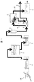
本発明の海水淡水化装置の一実施例を図1を用いて説明する。該図に示す如く、本実施例の海水淡水化装置は、海水100をポンプ等で取水し貯水する取水井1と、取水井1からの海水が二層濾過器2を経由し、この二層濾過器2で濾過された海水を貯水する濾過海水槽3と、濾過海水槽3からの濾過された海水が保安フィルター4を介して高圧ポンプ5で導かれ、淡水と塩分濃縮水に分離する逆浸透膜モジュール6と、この逆浸透膜モジュール6で分離された淡水を貯水する生産水槽8と、高圧ポンプ5と同軸に設置され、逆浸透膜モジュール6で分離された塩分濃縮水を回収して濃縮水配管9に排出する動力回収タービン7とを備え、これら取水井1と二層濾過器2、二層濾過器2と濾過海水槽3、濾過海水槽3と保安フィルター4、保安フィルター4と高圧ポンプ5、高圧ポンプ5と逆浸透膜モジュール6、逆浸透膜モジュール6と生産水槽8、逆浸透膜モジュール6と動力回収タービン7とが、それぞれ配管で接続されて構成されている。
An embodiment of the seawater desalination apparatus of the present invention will be described with reference to FIG. As shown in the figure, the seawater desalination apparatus of the present embodiment includes a intake well 1 that takes in and stores
そして、上記構成の海水淡水化装置において、金属配管が用いられるのは、高圧ポンプ5から下流の配管部分で、図1中の金属配管10、金属配管11、金属配管12が該当する。これらの金属配管10、11、12では、50気圧以上の内圧で海水が流動する。
In the seawater desalination apparatus having the above-described configuration, the metal pipe is used in the pipe portion downstream from the high-
これらの金属配管10、11、12では、塩濃度に依存する腐食現象が時間経過とともに発生し、特に、配管結合部であるフランジ部や表面組織と表面粗さが不均一となる溶接部では、反応速度が大きな腐食が進展する場合がある。
In these
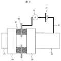
この腐食作用を抑制するために用いる本発明の腐食抑制装置の実施例1について、図2を用いて説明する。 Example 1 of the corrosion inhibiting apparatus of the present invention used for inhibiting this corrosive action will be described with reference to FIG.
該図に示す如く、本実施例の腐食抑制装置は、内部を海水が流通するステンレス配管25に一端が接続された配線22と、この配線22の途中に設置された電源23と、配線22の他端に接続され、ステンレス配管25とは電気的に絶縁されて設置されているアノード21と、配線22の途中に、アノード21とステンレス配管25の間の電流を計測する電流モニタ(電流計)24とから概略構成されている。尚、電流モニタ24は、無い場合もある。
As shown in the figure, the corrosion inhibiting device of this embodiment is composed of a
配線22は、ステンレス配管25とアノード21の電気的導通を取り、ステンレス配管25とアノード21間に電源23を介する。電流モニタ24は、電源23と直列に接続され、かつ、抵抗の少ない内部回路を有するものとする。また、電流モニタ24は、その電流値の減少を監視することで、アノード21の消耗を検知することができる。
The
アノード21は、ステンレス配管25の一部であるフランジ26の間に設置される円環状のゴムリング27(Oリング又は絶縁ガスケットとも呼ばれる)に挿入される。この際、ゴムリング27は2枚で、その間にアノード21が挿入される場合もある。このゴムリング27の水浸透率は、浸透した水が漏れないことを考慮すると、10%以下が望ましい。
The
アノード21は、ステンレス配管25内に流れる海水と接するように、ステンレス配管25の内面直径よりも内側にある表面積を持ち存在することが必要用件となる。また、アノード21はカーボンシートからなり、フランジ26を固定するボルトとは接触しないように、ボルト位置にボルト径以上の円空を有する。更に、アノード21の厚さは、材料力学的には100μm以上、かつ、構造的(大型化しない構造)には10mm以内で、海水の流速で破断することがない靭性を有している。
It is necessary for the
電源23は、一例として直流電源装置を用い、1Vを常にアノード21とステンレス配管25に印加するように制御する。電流値は100μA以下でも防食効果を有するので、アノード21の溶出を低減するために10μAのオーダとする。
The
このような腐食抑制装置により、フランジ26を含むステンレス配管25は、海水による腐食作用を受けるにもかかわらず、その腐食量を著しく低減することが可能となる。また、フランジ26のゴムリング27とのすき間部に生ずる腐食速度の大きなすき間腐食についても著しく抑制することができる。
With such a corrosion suppression device, the
従って、本実施例によれば、淡水化性能を維持しつつ、海水が流通する金属配管の耐食性を向上させることができる。 Therefore, according to the present Example, the corrosion resistance of the metal piping through which seawater flows can be improved while maintaining the desalination performance.
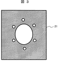
腐食抑制装置の実施例1におけるアノードについて、図3乃至図5を用いて説明する。 The anode in Example 1 of the corrosion inhibiting apparatus will be described with reference to FIGS.
図3に示すアノード21は、その形状が角型のシートから成るものである。アノード21はカーボンシートからなり、フランジを固定するボルトとは接触しないように、ボルト位置にボルト径以上の円空を有する。
The
図4に示すアノード21は、その形状が円型のシートから成るものである。アノード21はカーボンシートからなり、フランジを固定するボルトとは接触しないように、ボルト位置にボルト径以上の円空を有する。
The
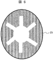
図5に示すアノード21は、その形状が短冊状のシートから成るものである。アノード21はカーボンシートからなり、フランジを固定するボルトとは接触しないように、短冊状のアノード21間のボルト位置にボルト径以上の空隙を有する。
The
図6に本発明の腐食抑制装置の実施例2を示す。該図に示す本実施例の腐食抑制装置は、そのアノードが、カーボンシート71と絶縁フィルム72から成るもので、他の構成は図2に示した実施例1と同様である。
FIG. 6 shows a second embodiment of the corrosion inhibiting device of the present invention. In the corrosion inhibiting apparatus of this embodiment shown in the figure, the anode is composed of a
そして、本実施例では、フランジ26を固定するボルトとは接触しないようにボルト位置にボルト径以上の円空を有すると共に、カーボンシート71と絶縁フィルム72から成るアノードは、ゴムリング27に挟まれることにより、フランジ26やステンレス配管25と海水側での直接の電気的導通は遮断される。
In this embodiment, the bolt position has a circular space larger than the bolt diameter so as not to contact the bolt that fixes the
このような本実施例の構成でも、実施例1と同様な効果を得ることができる。 Even with the configuration of this embodiment, the same effects as those of the first embodiment can be obtained.
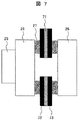
図7に本発明の腐食抑制装置の実施例3を示す。該図に示す本実施例の腐食抑制装置は、そのアノードが、カーボンシート71と2つの絶縁フィルム72及び73から成り、カーボンシート71が絶縁フィルム72と73で挟まれているもので、他の構成は図2に示した実施例1と同様である。
FIG. 7 shows a third embodiment of the corrosion inhibiting device of the present invention. In the corrosion inhibiting apparatus of this embodiment shown in the figure, the anode is composed of a
そして、本実施例では、フランジ26を固定するボルトとは接触しないようにボルト位置にボルト径以上の円空を有すると共に、カーボンシート71が絶縁フィルム72と73で挟まれているアノードは、ゴムリング27に挟まれることにより、フランジ26やステンレス配管25と海水側での直接の電気的導通は遮断される。
In this embodiment, the anode in which the bolt position is not less than the bolt diameter so that it does not come into contact with the bolt that fixes the
このような本実施例の構成でも、実施例1及び2と同様な効果を得ることができる。 Even with the configuration of this embodiment, the same effects as those of Embodiments 1 and 2 can be obtained.
本発明の海水淡水化装置における腐食抑制装置の効果について説明する。本発明の腐食抑制装置は、RO膜を用いた海水淡水化装置のみならず、多段マルチステップの加熱蒸気を用いた海水淡水化装置の金属配管を対象に実施される。 The effect of the corrosion inhibiting device in the seawater desalination apparatus of the present invention will be described. The corrosion suppression apparatus of the present invention is implemented not only for seawater desalination apparatuses using RO membranes but also for metal piping of seawater desalination apparatuses using multistage multi-step heating steam.
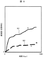
本発明の腐食抑制装置を用いたステンレス配管の腐食の進行について、図8を用いて説明する。 The progress of the corrosion of the stainless steel pipe using the corrosion suppression apparatus of the present invention will be described with reference to FIG.
図8は、図2に示す腐食抑制装置を用いて、SUS316L配管材料の室温人工海水中での500時間の浸漬実験を実施し、本装置を用いない場合と比較した結果である。該図において、Aは本発明を適用した場合の腐食量の経時変化であり、Bは本装置を用いずSUS316L配管材料を単純浸漬した場合の腐食量の経時変化を示し、25℃の空気飽和した塩濃度3.5%人工海水を、ステンレス鋼であるSUS316L鋼の配管に通水した場合の腐食量を経過時間を変数として求めた結果である。 FIG. 8 shows a result of a 500 hour immersion experiment in a room temperature artificial seawater of SUS316L piping material using the corrosion suppression apparatus shown in FIG. 2 and a comparison with a case where this apparatus is not used. In this figure, A is the change over time of the corrosion amount when the present invention is applied, B is the change over time of the corrosion amount when SUS316L piping material is simply immersed without using this apparatus, and air saturation at 25 ° C. It is the result of having calculated | required the corrosion amount at the time of letting the salt concentration 3.5% artificial seawater which passed the SUS316L steel piping which is stainless steel pass as a variable.
比較のための本発明の腐食抑制装置を用いず単純浸漬とした減肉量を示す腐食量変化901は、本発明の腐食抑制装置を接続したSUS316L鋼の腐食量変化902の5倍以上となり、本発明の腐食抑制装置により、ステンレス配管の腐食が著しく抑制されることがわかる。
For comparison, the
尚、本発明の腐食抑制装置では、アノードとしてカーボンテープを用い、配管がカーボンシートより-1Vとなる電圧を保持するように制御した。電源は、直流安定化電源を用いている。 In the corrosion inhibitor of the present invention, carbon tape was used as the anode, and the piping was controlled so as to maintain a voltage of -1 V from the carbon sheet. The power supply uses a DC stabilized power supply.
本発明の腐食抑制装置を用いたステンレス配管の腐食の進行について、図9を用いて説明する。 The progress of the corrosion of the stainless steel pipe using the corrosion inhibitor of the present invention will be described with reference to FIG.
図9は、図2に示す腐食抑制装置で電位付与を停止し、アノードとして低電位を示すカーボンテープを用いて、SUS316L配管材料の室温人工海水中での500時間の浸漬実験を実施し、本装置を用いない場合と比較した結果である。該図において、Aは本発明を適用した場合の腐食量の経時変化であり、Bは本装置を用いずSUS316L配管材料を単純浸漬した場合の腐食量の経時変化を示し、ブライン水(塩濃縮水)を想定した60℃の空気飽和した塩濃度7%の人工海水を、ステンレス鋼であるSUS316L鋼の配管に通水した場合の腐食量を経過時間を変数として求めた結果である。 FIG. 9 shows the result of a 500 hour immersion experiment in room temperature artificial seawater of SUS316L piping material using a carbon tape showing a low potential as an anode, with the potential application stopped by the corrosion inhibitor shown in FIG. It is the result compared with the case where an apparatus is not used. In the figure, A is the change with time of the corrosion amount when the present invention is applied, B is the change with time of the corrosion amount when SUS316L piping material is simply immersed without using this apparatus, and brine water (salt concentration) It is the result of obtaining the corrosion amount when passing artificial water with a salt concentration of 7%, which is air saturated at 60 ° C. assuming water), through a pipe of stainless steel SUS316L steel, using elapsed time as a variable.
比較のための本発明の腐食抑制装置を用いず単純浸漬とした減肉量を示す腐食量変化1001は、本発明の腐食抑制装置を接続したSUS316L鋼の腐食量変化1002の8倍以上となり、本発明の腐食抑制装置により、ステンレス配管の腐食が著しく抑制されることがわかる。
For comparison, the
尚、本発明の腐食抑制装置では、アノードとしてカーボンシートを用い、配管がカーボンシートより-1Vとなる電圧を保持するように制御した。電源は、直流安定化電源を用いている。 In the corrosion inhibitor of the present invention, a carbon sheet was used as the anode, and the piping was controlled so as to maintain a voltage of -1 V from the carbon sheet. The power supply uses a DC stabilized power supply.
次に、本発明のポンプ装置の一実施例を図10及び図11を用いて説明する。該図に示す本実施例のポンプ装置は、上述した海水淡水化装置の設備の一つであるポンプ装置を示すものである。 Next, an embodiment of the pump device of the present invention will be described with reference to FIGS. The pump apparatus of the present embodiment shown in the figure shows a pump apparatus that is one of the facilities of the seawater desalination apparatus described above.
図10は、本実施例のポンプ装置の一つである斜流ポンプの概略、図11は、その吸い込み部の拡大を示すものである。尚、斜流ポンプ以外のポンプ装置においても類似の構造となる。 FIG. 10 shows an outline of a mixed flow pump which is one of the pump devices of this embodiment, and FIG. 11 shows an enlargement of the suction portion. In addition, it becomes a similar structure also in pump apparatuses other than a mixed flow pump.
該図に示す如く、本実施例のポンプ装置は、シャフト35を中心として、それを支える上部軸受ブラケット32と下部軸受ブラケット33、更に、シャフト35の回転に伴い回転する羽根車37と、水流の容器となる揚水管30とを備え、揚水管30は、吐出ケーシング31と吸込ケーシング34で保持され、羽根車37でもたらされる水流が、案内羽根36を介して図10の左方へ移動する水流となり、揚水されるものである。
As shown in the drawing, the pump apparatus of this embodiment, around the
そして、本実施例での腐食抑制装置は、揚水管30の外部に、上述した実施例で説明した配線22、電源23、電流モニタ24を配置し、アノード21或いはカーボンシート71が、上部軸受ブラケット32と下部軸受ブラケット33及び吸込ケーシング34のフランジ部に、図2、図6、図7のいずれかに示す形状で水流と接するように設置される。電流モニタ24は無い場合もある。
And the corrosion suppression apparatus in a present Example arrange | positions the
配線22は、下部軸受ブラケット33、揚水管30、吐出ケーシング31、吸込ケーシング34及び羽根車37に接続され、これら構造材が、アノード21或いはカーボンシート71に対して負の電位を保持するように電源23により電圧が印加される。
このような本実施例の構成とすることでも、海水による腐食作用を受けるにもかかわらず、構造材の腐食量を著しく低減することが可能となる。 Even with the configuration of the present embodiment, the amount of corrosion of the structural material can be remarkably reduced despite being corroded by seawater.
従って、本実施例によれば、ポンプ装置の性能を維持しつつ、海水による耐食性を向上させることができる。 Therefore, according to the present Example, the corrosion resistance by seawater can be improved, maintaining the performance of a pump apparatus.
本発明は、海水淡水化装置の配管及び金属性構成部材の耐食性の向上に適用することができる。 The present invention can be applied to the improvement of the corrosion resistance of piping and metallic components of a seawater desalination apparatus.
1…取水井、2…二層濾過器、3…濾過海水槽、4…保安フィルター、5…高圧ポンプ、6…逆浸透膜モジュール、7…動力回収タービン、8…生産水槽、9…濃縮水配管、10、11、12…金属配管、21…アノード、22…配線、23…電源、24…電流モニタ、25…ステンレス配管、26…フランジ、27…ゴムリング、30…揚水管、31…吐出ケーシング、32…上部軸受ブラケット、33…下部軸受ブラケット、34…吸込ケーシング、35…シャフト、36…案内羽根、37…羽根車、71…カーボンシート、72…絶縁フィルム、100…海水。
DESCRIPTION OF SYMBOLS 1 ... Intake well, 2 ... Two-layer filter, 3 ... Filtration seawater tank, 4 ... Security filter, 5 ... High pressure pump, 6 ... Reverse osmosis membrane module, 7 ... Power recovery turbine, 8 ... Production tank, 9 ...
Claims (10)
前記アノードは、カーボンシート、炭素膜、グラファイト、フェライトの少なくとも1つから形成されると共に、前記金属配管の内面直径よりも内側にある表面積を持ち、前記フランジを固定するボルト位置に該ボルト径以上の円空を有して前記金属配管内を流れる海水と接するように設置され、かつ、該アノードと前記金属配管とは前記配線を介して電気的に導通され、前記金属配管にマイナスの電位を付与することを特徴とする腐食抑制装置。 A wiring having one end connected to the metal pipe an internal seawater flows, is connected to the other end of the wire, and the metal pipe, inserted into the rubber ring disposed between the flanges is a part of the metal pipe an anode which is electrically installed insulated with the fact that the, is provided in the middle of the wiring, and a DC power supply generating a potential difference to the metal pipe and the anode,
The anode is formed of at least one of a carbon sheet, a carbon film, graphite, and ferrite, and has a surface area inside the inner diameter of the metal pipe, and is larger than the bolt diameter at a bolt position for fixing the flange. The anode and the metal pipe are electrically connected to each other through the wiring, and a negative potential is applied to the metal pipe. A corrosion inhibitor characterized by being applied.
前記配線の途中に、前記アノードと金属配管の間の電流を計測する電流計を備えていることを特徴とする腐食抑制装置。 The corrosion inhibitor according to claim 1 ,
A corrosion control apparatus comprising an ammeter for measuring a current between the anode and the metal pipe in the middle of the wiring.
前記アノードは、角型、円型或いは短冊状のカーボンシートから形成されていることを特徴とする腐食抑制装置。 The corrosion inhibitor according to claim 1,
The said anode is formed from the square, circular, or strip-shaped carbon sheet, The corrosion suppression apparatus characterized by the above-mentioned.
前記アノードは、カーボンシートと絶縁フィルムから形成されていることを特徴とする腐食抑制装置。 The corrosion inhibitor according to claim 1,
The said corrosion suppression apparatus characterized by the said anode being formed from the carbon sheet and the insulating film.
前記カーボンシートは、2つの絶縁フィルムに挟まれていることを特徴とする腐食抑制装置。 The corrosion control device according to claim 4 ,
The said carbon sheet is pinched | interposed into two insulating films, The corrosion suppression apparatus characterized by the above-mentioned.
少なくとも前記高圧ポンプから下流に位置する前記配管に、請求項1乃至5のいずれか1項に記載の腐食抑制装置が設置されていることを特徴とする海水淡水化装置。 An intake well for storing the taken-in seawater, a filtered seawater tank for storing the seawater from the intake well through which the seawater is filtered, and the filtered seawater from the filtered seawater tank A reverse osmosis membrane module that is guided by a high-pressure pump through a safety filter and separated into fresh water and salt-concentrated water, a production water tank that stores fresh water separated by the reverse osmosis membrane module, and a coaxial installation with the high-pressure pump A seawater desalination apparatus comprising a power recovery turbine that recovers the salt-concentrated water separated by the reverse osmosis membrane module and discharges the concentrated salt water to a concentrated water pipe;
The seawater desalination apparatus according to any one of claims 1 to 5 , wherein the corrosion suppression apparatus according to any one of claims 1 to 5 is installed at least in the pipe located downstream from the high-pressure pump.
前記配管の対向するフランジ間にゴムリングが設置され、該ゴムリングに前記腐食抑制装置のアノードが挿入されていることを特徴とする海水淡水化装置。 The seawater desalination apparatus according to claim 6 ,
A seawater desalination apparatus, wherein a rubber ring is installed between the opposing flanges of the pipe, and an anode of the corrosion inhibiting apparatus is inserted into the rubber ring.
前記ゴムリングの水浸透率が10%以下であることを特徴とする海水淡水化装置。 The seawater desalination apparatus according to claim 7 ,
A seawater desalination apparatus, wherein the rubber ring has a water permeability of 10% or less.
前記揚水管の外部に、少なくとも配線及び電源が配置され、アノード或いはカーボンシートが、前記上部軸受ブラケットと下部軸受ブラケット及び吸込ケーシングのフランジ部に、水流と接するように設置されている請求項1乃至5のいずれか1項に記載の腐食抑制装置を備えていることを特徴とするポンプ装置。 A shaft, around the shaft, for holding the upper bearing bracket and a lower shaft 受Bu racket supporting it, and an impeller that rotates in accordance with rotation of the shaft, and a riser pipe serving as a water container, a該揚water pipe and a discharge casing and intake Comike pacing, water caused by the impeller, the pump unit comprising a water flow to move to the riser pipe through the guide vanes,
Outside of the riser pipe, at least the wiring and the power supply are arranged, the anode or carbon sheet, the flange portion of the upper bearing bracket and the lower shaft 受Bu racket and intake Comike pacing is installed in contact with the water flow A pump device comprising the corrosion inhibiting device according to any one of claims 1 to 5 .
前記配線は、前記下部軸受ブラケット、揚水管、吐出ケーシング、吸込ケーシング及び羽根車に接続され、これらが、前記アノード或いはカーボンシートに対して負の電位を保持するように電源により電圧が印加されることを特徴とするポンプ装置。 The pump device according to claim 9 ,
Wherein the wiring, the lower shaft 受Bu racket, lifting pipe, discharge casing, is connected to the suction Comike pacing and impeller, these are the voltage by the power source to hold a negative potential relative to the anode or carbon sheet Is applied to the pump device.
Priority Applications (4)
| Application Number | Priority Date | Filing Date | Title |
|---|---|---|---|
| JP2012120346A JP5877125B2 (en) | 2012-05-28 | 2012-05-28 | Corrosion suppression device, seawater desalination device and pump device provided with the same |
| CN201380028158.3A CN104364422A (en) | 2012-05-28 | 2013-05-07 | Corrosion inhibition device, and seawater desalination device and pump device equipped with same |
| PCT/JP2013/062813 WO2013179858A1 (en) | 2012-05-28 | 2013-05-07 | Corrosion inhibition device, and seawater desalination device and pump device equipped with same |
| IN10044DEN2014 IN2014DN10044A (en) | 2012-05-28 | 2013-05-07 |
Applications Claiming Priority (1)
| Application Number | Priority Date | Filing Date | Title |
|---|---|---|---|
| JP2012120346A JP5877125B2 (en) | 2012-05-28 | 2012-05-28 | Corrosion suppression device, seawater desalination device and pump device provided with the same |
Publications (2)
| Publication Number | Publication Date |
|---|---|
| JP2013245380A JP2013245380A (en) | 2013-12-09 |
| JP5877125B2 true JP5877125B2 (en) | 2016-03-02 |
Family
ID=49673062
Family Applications (1)
| Application Number | Title | Priority Date | Filing Date |
|---|---|---|---|
| JP2012120346A Expired - Fee Related JP5877125B2 (en) | 2012-05-28 | 2012-05-28 | Corrosion suppression device, seawater desalination device and pump device provided with the same |
Country Status (4)
| Country | Link |
|---|---|
| JP (1) | JP5877125B2 (en) |
| CN (1) | CN104364422A (en) |
| IN (1) | IN2014DN10044A (en) |
| WO (1) | WO2013179858A1 (en) |
Families Citing this family (7)
| Publication number | Priority date | Publication date | Assignee | Title |
|---|---|---|---|---|
| SG11201604516VA (en) * | 2013-12-04 | 2016-07-28 | Hitachi Ltd | Impressed current protect system |
| JP2015187295A (en) * | 2014-03-27 | 2015-10-29 | 株式会社日立製作所 | Electrical protection system |
| JP6276124B2 (en) * | 2014-07-07 | 2018-02-07 | 株式会社日立製作所 | Cathodic protection method and cathodic protection system |
| CN104214468B (en) * | 2014-07-31 | 2016-06-29 | 西安石油大学 | A kind of external sacrificial anode prevents pipeline inner wall corrosion device and method |
| CN106016336B (en) * | 2016-06-24 | 2017-12-19 | 桂林市淦隆环保科技有限公司 | Corrosion-resistant alcohol-based fuel oil pump and anti-corrosion method |
| CN108176228A (en) * | 2018-03-02 | 2018-06-19 | 秦皇岛天秦装备制造股份有限公司 | A kind of anti-mixing pressure vessel for reverse osmosis |
| CN108796509A (en) * | 2018-08-23 | 2018-11-13 | 温州嘉伟环保科技有限公司 | A kind of water pump and pipe fitting protective device for strong corrosive sewage reverse osmosis membrane |
Family Cites Families (9)
| Publication number | Priority date | Publication date | Assignee | Title |
|---|---|---|---|---|
| GB1494200A (en) * | 1974-01-23 | 1977-12-07 | Tba Industrial Products Ltd | Gaskets |
| JPS50109351A (en) * | 1974-02-09 | 1975-08-28 | ||
| JPS5725227A (en) * | 1980-07-21 | 1982-02-10 | Nisshin Steel Co Ltd | Joining method of stainless steel pipe |
| JPH06101685A (en) * | 1992-09-10 | 1994-04-12 | Hitachi Ltd | Vertical shaft pump |
| JPH07260062A (en) * | 1994-03-23 | 1995-10-13 | Nishikawa Rubber Co Ltd | Packing material for electrolytic solution contact pipe |
| JPH08303597A (en) * | 1995-05-02 | 1996-11-19 | Mitsubishi Heavy Ind Ltd | Rubber gasket for flange and tightening method therefor |
| JPH1150278A (en) * | 1997-08-01 | 1999-02-23 | Hitachi Zosen Tomioka Kikai Kk | Electrode for electrical rust prevention of piping |
| JPH1192981A (en) * | 1997-09-12 | 1999-04-06 | Mitsubishi Materials Corp | Electric corrosion protection structure to crevice corrosion between piping flange |
| JP4870648B2 (en) * | 2007-10-25 | 2012-02-08 | 株式会社荏原製作所 | Power recovery system |
-
2012
- 2012-05-28 JP JP2012120346A patent/JP5877125B2/en not_active Expired - Fee Related
-
2013
- 2013-05-07 IN IN10044DEN2014 patent/IN2014DN10044A/en unknown
- 2013-05-07 WO PCT/JP2013/062813 patent/WO2013179858A1/en active Application Filing
- 2013-05-07 CN CN201380028158.3A patent/CN104364422A/en active Pending
Also Published As
| Publication number | Publication date |
|---|---|
| IN2014DN10044A (en) | 2015-08-14 |
| WO2013179858A1 (en) | 2013-12-05 |
| JP2013245380A (en) | 2013-12-09 |
| CN104364422A (en) | 2015-02-18 |
Similar Documents
| Publication | Publication Date | Title |
|---|---|---|
| JP5877125B2 (en) | Corrosion suppression device, seawater desalination device and pump device provided with the same | |
| Badawy et al. | Environmentally safe corrosion inhibition of the Cu–Ni alloys in acidic sulfate solutions | |
| US8511370B2 (en) | Heat exchanger including selectively activated cathodic protection useful in sulfide contaminated environments | |
| US3342712A (en) | Water conditioning method and apparatus | |
| WO2015083580A1 (en) | Electric anticorrosion system | |
| JP5879216B2 (en) | Seawater desalination equipment | |
| CN104947117B (en) | Electric anticorrosion system, sea water pump and sea water desalinating unit | |
| US6540886B1 (en) | Cathodic protection system utilizing a membrane | |
| Han et al. | Asymmetrical electrode system for stable operation of a large-scale reverse electrodialysis (RED) system | |
| JP2012197502A (en) | Method and device for electrolytic protection of stainless steel | |
| JP6276124B2 (en) | Cathodic protection method and cathodic protection system | |
| JP6585976B2 (en) | Electrocorrosion protection system and seawater desalination plant equipped with the same | |
| Feng et al. | The corrosion behavior of T2 brass in power plant generator stator cooling water | |
| JP7082002B2 (en) | Electrolytic cell and how to use it | |
| JP2019116650A (en) | Electric corrosion prevention system and electrolyte desalination plant | |
| JP3834781B2 (en) | Electrolytic antifouling device and method for small diameter seawater pipes | |
| JPH1136088A (en) | Electrolytic corrosion protection method capable of executing sea water electrolytic fouling prevention and iron oxide film formation by generation of iron ion and apparatus therefor | |
| JP6766004B2 (en) | Electrocorrosion protection system and seawater desalination plant equipped with it | |
| CN108796509A (en) | A kind of water pump and pipe fitting protective device for strong corrosive sewage reverse osmosis membrane | |
| RU2596514C2 (en) | Method of cathode protection of impeller with blades of turbine of hydraulic unit from corrosion and cavitation destruction | |
| Hasan et al. | Cathodic Protection of Carbon Steel in 0.1 N NaCl Solution under Flow Conditions Using Rotating Cylinder Electrode | |
| JP7312593B2 (en) | Liquid handling system and adsorption system | |
| JP2017095892A (en) | Antifouling device for seawater utilization structure, antifouling device for seawater pump, and seawater pollution prevention method | |
| KR20110008392A (en) | Electrolytic cell | |
| RU180152U1 (en) | DEVICE FOR PROTECTING STEEL PIPES FROM INTERNAL CORROSION |
Legal Events
| Date | Code | Title | Description |
|---|---|---|---|
| A621 | Written request for application examination |
Free format text: JAPANESE INTERMEDIATE CODE: A621 Effective date: 20141225 |
|
| A131 | Notification of reasons for refusal |
Free format text: JAPANESE INTERMEDIATE CODE: A131 Effective date: 20151104 |
|
| A521 | Request for written amendment filed |
Free format text: JAPANESE INTERMEDIATE CODE: A523 Effective date: 20151218 |
|
| TRDD | Decision of grant or rejection written | ||
| A01 | Written decision to grant a patent or to grant a registration (utility model) |
Free format text: JAPANESE INTERMEDIATE CODE: A01 Effective date: 20160112 |
|
| A61 | First payment of annual fees (during grant procedure) |
Free format text: JAPANESE INTERMEDIATE CODE: A61 Effective date: 20160125 |
|
| R150 | Certificate of patent or registration of utility model |
Ref document number: 5877125 Country of ref document: JP Free format text: JAPANESE INTERMEDIATE CODE: R150 |
|
| LAPS | Cancellation because of no payment of annual fees |