JP7082002B2 - Electrolytic cell and how to use it - Google Patents
Electrolytic cell and how to use it Download PDFInfo
- Publication number
- JP7082002B2 JP7082002B2 JP2018134265A JP2018134265A JP7082002B2 JP 7082002 B2 JP7082002 B2 JP 7082002B2 JP 2018134265 A JP2018134265 A JP 2018134265A JP 2018134265 A JP2018134265 A JP 2018134265A JP 7082002 B2 JP7082002 B2 JP 7082002B2
- Authority
- JP
- Japan
- Prior art keywords
- electrolytic cell
- valve
- header
- current
- flow path
- Prior art date
- Legal status (The legal status is an assumption and is not a legal conclusion. Google has not performed a legal analysis and makes no representation as to the accuracy of the status listed.)
- Active
Links
Images


Classifications
-
- Y—GENERAL TAGGING OF NEW TECHNOLOGICAL DEVELOPMENTS; GENERAL TAGGING OF CROSS-SECTIONAL TECHNOLOGIES SPANNING OVER SEVERAL SECTIONS OF THE IPC; TECHNICAL SUBJECTS COVERED BY FORMER USPC CROSS-REFERENCE ART COLLECTIONS [XRACs] AND DIGESTS
- Y02—TECHNOLOGIES OR APPLICATIONS FOR MITIGATION OR ADAPTATION AGAINST CLIMATE CHANGE
- Y02P—CLIMATE CHANGE MITIGATION TECHNOLOGIES IN THE PRODUCTION OR PROCESSING OF GOODS
- Y02P20/00—Technologies relating to chemical industry
- Y02P20/10—Process efficiency
- Y02P20/133—Renewable energy sources, e.g. sunlight
Landscapes
- Electrolytic Production Of Non-Metals, Compounds, Apparatuses Therefor (AREA)
Description
本発明は、電解槽及びその使用方法に関する。 The present invention relates to an electrolytic cell and a method of using the same.
電気分解技術を産業に応用することは古くから行われており、例えば、食塩水の電気分解による苛性ソーダ・塩素の製造、次亜塩素酸の製造、アルカリイオン水、オゾン水の製造等多岐にわたっている。これまでも、設備コストの低減、電解効率の向上や装置の耐久性の向上等を目指した種々の提案がなされてきている。
近年、二酸化炭素等の温室効果ガスによる地球温暖化、化石燃料の埋蔵量の減少等の問題を解決するため、再生可能エネルギーを利用した風力発電や太陽光発電等の技術が注目されている。
The application of electrolysis technology to industry has been practiced for a long time, for example, in the production of caustic soda / chlorine by electrolysis of salt water, the production of hypochlorous acid, the production of alkaline ionized water, and the production of ozone water. .. Various proposals have been made with the aim of reducing equipment costs, improving electrolysis efficiency, and improving the durability of equipment.
In recent years, in order to solve problems such as global warming caused by greenhouse gases such as carbon dioxide and a decrease in fossil fuel reserves, technologies such as wind power generation and solar power generation using renewable energy have been attracting attention.
再生可能エネルギーは、出力が気候条件に依存するため、その変動が非常に大きいという性質がある。そのため、再生可能エネルギーによる発電で得られた電力を一般電力系統に輸送することが常に可能とはならず、電力需給のアンバランスや電力系統の不安定化等の社会的な影響が懸念されている。 Renewable energy has the property that its output is very variable because its output depends on climatic conditions. Therefore, it is not always possible to transport the electric power obtained from power generation by renewable energy to the general electric power system, and there are concerns about social impacts such as imbalance of electric power supply and demand and destabilization of the electric power system. There is.
そこで、再生可能エネルギーから発電された電力を、貯蔵及び輸送が可能な形に代えて、これを利用しようとする研究が行われている。具体的には、再生可能エネルギーから発電された電力を利用した水の電気分解(電解)により、貯蔵及び輸送が可能な水素を発生させ、水素をエネルギー源や原料として利用することが検討されている。 Therefore, research is being conducted to replace the electric power generated from renewable energy with a form that can be stored and transported. Specifically, it has been considered to generate hydrogen that can be stored and transported by electrolysis (electrolysis) of water using electricity generated from renewable energy, and to use hydrogen as an energy source or a raw material. There is.
水素は、石油精製、化学合成、金属精製等の場面において、工業的に広く利用されており、近年では、燃料電池車(FCV)向けの水素ステーションやスマートコミュニティ、水素発電所等における利用の可能性も広がっている。このため、再生可能エネルギーから特に高純度の水素を得る技術の開発に対する期待は高い。 Hydrogen is widely used industrially in the fields of petroleum refining, chemical synthesis, metal refining, etc., and in recent years, it can be used in hydrogen stations for fuel cell vehicles (FCVs), smart communities, hydrogen power plants, etc. The sex is also spreading. Therefore, there are high expectations for the development of technology for obtaining high-purity hydrogen from renewable energy.
水の電気分解の方法としては、固体高分子型水電解法、高温水蒸気電解法、アルカリ水電解法等がある。この中で、数十年以上前から工業化されていること、大規模に実施することができること、他の水電解装置に比べると安価であること等から、アルカリ水電解は特に有力なものの一つとされている。 Examples of the method for electrolyzing water include a solid polymer type water electrolysis method, a high temperature steam electrolysis method, and an alkaline water electrolysis method. Among them, alkaline water electrolysis is one of the most promising ones because it has been industrialized for more than several decades, it can be carried out on a large scale, and it is cheaper than other water electrolyzers. Has been done.
しかしながら、アルカリ水電解を今後エネルギーの貯蔵及び輸送のための手段として適応させるためには、前述のとおり出力の変動が大きい電力を効率的且つ安定的に利用して水電解を行うことを可能にする必要がある。そのため、アルカリ水電解用等の電解セルや装置の諸課題を解決することが求められている。 However, in order to adapt alkaline water electrolysis as a means for storing and transporting energy in the future, as described above, it is possible to efficiently and stably use electric power with large fluctuations in output to perform water electrolysis. There is a need to. Therefore, it is required to solve various problems of electrolytic cells and devices for electrolysis of alkaline water.
アルカリ水電解において電解電圧を低く抑えて、水素製造の電力原単位を改善するという課題を解決するためには、電解セルの構造として、特に、隔膜と電極との隙間を実質的に無くした構造である、ゼロギャップ構造と呼ばれる構造を採用することが有効なことはよく知られている(特許文献1、2参照)。ゼロギャップ構造では、発生するガスを電極の細孔を通して電極の隔膜側とは反対側に素早く逃がすことによって、電極間の距離を低減しつつ、電極近傍におけるガス溜まりの発生を極力抑えて、電解電圧を低く抑制している。ゼロギャップ構造は、電解電圧の抑制にきわめて有効であり、種々の電解装置に採用されている。 In order to solve the problem of improving the power intensity of hydrogen production by keeping the electrolytic voltage low in alkaline water electrolysis, the structure of the electrolytic cell, in particular, a structure in which the gap between the diaphragm and the electrode is substantially eliminated. It is well known that it is effective to adopt a structure called a zero gap structure (see Patent Documents 1 and 2). In the zero gap structure, the generated gas is quickly released through the pores of the electrode to the side opposite to the diaphragm side of the electrode, thereby reducing the distance between the electrodes and suppressing the generation of gas pools in the vicinity of the electrodes as much as possible for electrolysis. The voltage is suppressed low. The zero gap structure is extremely effective in suppressing the electrolytic voltage, and is used in various electrolytic devices.
しかしながら、例えば、変動電源下での使用の場合には電解停止が頻繁に生じることから、電極をより長い期間に亘って使用できるように改良された電解セルが求められていた。
そこで、本発明は、電解停止時に生じる逆電流により、電極が劣化して過電圧が上昇することを抑制することを目的とする。
However, for example, in the case of use under a variable power supply, electrolytic cell is frequently stopped, so that an improved electrolytic cell is required so that the electrode can be used for a longer period of time.
Therefore, an object of the present invention is to prevent the electrode from deteriorating and the overvoltage from rising due to the reverse current generated when the electrolysis is stopped.
発明者らは、従来の電解セルにおいては、電解停止時に、電極室に電解液を供給する流路により漏洩電流回路が形成されて、自己放電を生じることを見出した。かかる自己放電は、通電面に流れる電流の向きが、電解時の電流の向きと逆向きであるため、逆電流とも称される。上記逆電流が生じる過程では、電極(陰極及び陽極)が酸化還元され、活性化溶解や体積膨張収縮が生じ、電極が失活して過電圧が上昇するおそれがあることを知見した。 The inventors have found that in a conventional electrolytic cell, a leakage current circuit is formed by a flow path for supplying an electrolytic solution to an electrode chamber when electrolysis is stopped, and self-discharge occurs. Such self-discharge is also referred to as reverse current because the direction of the current flowing on the energized surface is opposite to the direction of the current during electrolysis. It has been found that in the process of generating the reverse current, the electrodes (cathode and anode) are redoxed, activated and dissolved, and volume expansion and contraction occur, and the electrodes may be deactivated and the overvoltage may increase.
本発明の要旨は以下の通りである。
[1]
電極室と該電極室に連通する流路と、
前記流路を遮断可能な電流遮断弁と、
を備え、
前記流路は、前記電極室の入口側の流路及び出口側の流路を含み、
前記電流遮断弁は、前記入口側の流路及び前記出口側の流路それぞれに設けられていることを特徴とする、電解槽。
[2]
前記流路を備え前記電極室に連通するヘッダー、前記流路を備え前記ヘッダーに連通する導管からなる群から選ばれる少なくとも一つをさらに備える、[1]に記載の電解槽。
[3]
前記電流遮断弁が絶縁性材料を含む、[1]又は[2]に記載の電解槽。
[4]
前記電流遮断弁が設けられている箇所に対応する前記流路の部分が絶縁性材料を含む、[1]~[3]のいずれかに記載の電解槽。
[5]
前記電流遮断弁が前記流路のうち最も断面積が小さい箇所に設けられる、[1]~[4]のいずれかに記載の電解槽。
[6]
前記電流遮断弁が手動、ガス圧力、電気エネルギーからなる群から選ばれる少なくとも一つにより駆動される、[1]~[5]のいずれかに記載の電解槽。
[7]
前記電流遮断弁がボール弁、グローブ弁、ゲート弁、バタフライ弁、ダイヤフラム弁、チャッキ弁からなる群から選ばれる少なくとも一つである、[1]~[6]のいずれかに記載の電解槽。
[8]
[1]~[7]のいずれかに記載の電解槽において、電解停止前又は電解停止後に前記電流遮断弁を閉じることを特徴とする、電解槽の使用方法。
[9]
電解停止後2時間以内に前記電流遮断弁を閉じる、[8]に記載の電解槽の使用方法。
[10]
電解停止後30秒以内に前記電流遮断弁を閉じる、[9]に記載の電解槽の使用方法。
[11]
電解再開後60秒以内に前記電流遮断弁を開ける、[9]又は[10]に記載の電解槽の使用方法。
The gist of the present invention is as follows.
[1]
The electrode chamber and the flow path communicating with the electrode chamber ,
A current isolation valve that can interrupt the flow path,
Equipped with
The flow path includes a flow path on the inlet side and a flow path on the outlet side of the electrode chamber.
The electrolytic cell is characterized in that the current cutoff valve is provided in each of the inlet side flow path and the outlet side flow path .
[ 2 ]
The electrolytic cell according to [1 ], further comprising at least one selected from the group consisting of a header having the flow path and communicating with the electrode chamber, and a conduit having the flow path and communicating with the header.
[ 3 ]
The electrolytic cell according to [1] or [2], wherein the current cutoff valve contains an insulating material.
[ 4 ]
The electrolytic cell according to any one of [1] to [ 3 ], wherein the portion of the flow path corresponding to the portion where the current cutoff valve is provided contains an insulating material.
[ 5 ]
The electrolytic cell according to any one of [1] to [ 4 ], wherein the current cutoff valve is provided at a position having the smallest cross-sectional area in the flow path.
[ 6 ]
The electrolytic cell according to any one of [1] to [ 5 ], wherein the current isolation valve is driven by at least one selected from the group consisting of manual, gas pressure, and electric energy.
[ 7 ]
The electrolytic cell according to any one of [1] to [ 6 ], wherein the current cutoff valve is at least one selected from the group consisting of a ball valve, a globe valve, a gate valve, a butterfly valve, a diaphragm valve, and a check valve.
[ 8 ]
The method for using the electrolytic cell according to any one of [1] to [ 7 ], wherein the current shutoff valve is closed before or after the electrolysis is stopped.
[ 9 ]
The method of using the electrolytic cell according to [ 8 ], wherein the current shutoff valve is closed within 2 hours after the electrolysis is stopped.
[ 10 ]
The method of using the electrolytic cell according to [ 9 ], wherein the current shutoff valve is closed within 30 seconds after the electrolysis is stopped.
[ 11 ]
The method for using an electrolytic cell according to [9] or [10 ] , wherein the current cutoff valve is opened within 60 seconds after resuming electrolysis.
本発明によれば、電解停止時に生じる逆電流により、電極が劣化して過電圧が上昇することを抑制することができる。 According to the present invention, it is possible to prevent the electrode from deteriorating and the overvoltage from rising due to the reverse current generated when the electrolysis is stopped.
以下、本発明を実施するための形態(以下、「本実施形態」という)について詳細に説明する。なお、本発明は、以下の実施の形態に限定されるものではなく、その要旨の範囲内で種々変形して実施することができる。 Hereinafter, embodiments for carrying out the present invention (hereinafter referred to as “the present embodiment”) will be described in detail. The present invention is not limited to the following embodiments, and can be variously modified and implemented within the scope of the gist thereof.
(電解槽)
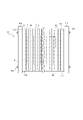
図1に、本実施形態のアルカリ水電解用複極式電解槽の一例の全体について側面図で示す。
本実施形態のアルカリ水電解用複極式電解槽50は、特に限定されないが、例えば、図1に示すとおり、陽極2aと、陰極2cと、陽極2aと陰極2cとを隔離する隔壁1と、隔壁1を縁取る外枠3とを備える複数の複極式エレメント60が隔膜4を挟んで重ね合わせられている複極式電解槽50としてよい。
(Electrolytic cell)
FIG. 1 is a side view showing an entire example of a multi-pole electrolytic cell for alkaline water electrolysis of the present embodiment.
The bipolar
複極式は、多数のセルを電源に接続する方法の1つであり、片面が陽極2a、片面が陰極2cとなる複数の複極式エレメント60を同じ向きに並べて直列に接続し、両端のみを電源に接続する方法である。
複極式電解槽50は、電源の電流を小さくできるという特徴を持ち、電解により化合物や所定の物質等を短時間で大量に製造することができる。電源設備は出力が同じであれば、低電流、高電圧の方が安価でコンパクトになるため、工業的には単極式よりも複極式の方が好ましい。
The multi-pole type is one of the methods for connecting a large number of cells to a power source. A plurality of
The multi-pole
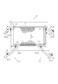
図2に、本実施形態のアルカリ水電解用複極式電解槽の一例の電解室、ヘッダー、導管について斜視図で示す。
本実施形態における複極式電解槽50では、電解槽50に電解液が通過する電極室5が画成されており、特に限定されないが、例えば、図2に示すとおり、隔壁1と外枠3と隔膜4とにより、電極室5が画成されていてよい。
また、本実施形態における複極式電解槽50は、電極室5に連通するヘッダー10を備え、特に限定されないが、例えば、図2に示すとおり、外枠3の外方にヘッダー10を備えていてよい。
さらに、本実施形態における複極式電解槽50は、ヘッダー10に配液又は集液されたガスや電解液を集める管である導管20が取り付けられていてよい。
FIG. 2 is a perspective view showing an electrolytic cell, a header, and a conduit of an example of a bipolar electrolytic cell for alkaline water electrolysis of the present embodiment.
In the multi-pole
Further, the bipolar
Further, in the bipolar
本実施形態のアルカリ水電解用複極式電解槽50は、図2に示すように、電極室と該電極室に連通する流路とを備え、流路に電流遮断弁が設けられていることを特徴とする。
上記構成により、電解槽50の電解セル65への通電が停止された場合に、電流遮断弁を閉じることによって、電極室に電解液を供給する流路により形成される漏洩電流回路を、容易に、迅速に、確実に、遮断して、逆電流の発生を可及的に防止することができる。そのため、本実施形態の電解槽50によれば、電解停止時に生じる逆電流により電極が劣化することを抑制することができる。
As shown in FIG. 2, the bipolar
With the above configuration, when the energization of the
本実施形態では、図2に示すように、電流遮断弁が流路を遮断可能なように設けられる。
ここで、「流路を遮断する」とは、上記逆電流の発生をなくす、又は最小化することをいい、具体的には、上記漏洩電流の電流密度を0.1mA/m2以下にすることをいう。
In the present embodiment, as shown in FIG. 2, a current cutoff valve is provided so as to be able to shut off the flow path.
Here, "cutting off the flow path" means eliminating or minimizing the generation of the reverse current, specifically, setting the current density of the leakage current to 0.1 mA / m 2 or less. That means.
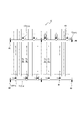
図3に、本実施形態の外部ヘッダー型のアルカリ水電解用複極式電解槽の例を平面図で示す。
本実施形態では、電解槽50は、図2、図3に示すように、流路を備え電極室に連通するヘッダー10、流路を備えヘッダー10に連通する導管20をさらに備えていてよく、電流遮断弁は、図2、図3に示すように、ヘッダー10、導管20に設けられていてよい。
FIG. 3 shows a plan view of an example of the external header type multi-pole electrolytic cell for alkaline water electrolysis of the present embodiment.
In the present embodiment, as shown in FIGS. 2 and 3, the
本実施形態では、電流遮断弁が絶縁性材料を含むことが好ましい。 In this embodiment, it is preferable that the current isolation valve contains an insulating material.
本実施形態では、電流遮断弁が設けられている箇所に対応するヘッダーの部分が絶縁性材料を含むことが好ましい。
絶縁性材料としては、詳細には、フッ素ゴム(FKM)、ニトリルゴム(NBR)、テトラフルオロエチレンプロピレンゴム(FEPM)、パーフロロゴム(FFKM)、エチレンプロピレンゴム(EPDM)、四フッ化エチレン樹脂(PTFE)、ポリフッ化ビニリデン(PVDF)、ポリプロピレン(PP)、ポリフェニレンスルファイド(PPS)等が挙げられる。
In the present embodiment, it is preferable that the portion of the header corresponding to the portion where the current cutoff valve is provided contains an insulating material.
The insulating materials include, in detail, fluorine rubber (FKM), nitrile rubber (NBR), tetrafluoroethylene propylene rubber (FEPM), perfluoro rubber (FFKM), ethylene propylene rubber (EPDM), and tetrafluoroethylene resin (PTFE). ), Polyvinylidene fluoride (PVDF), polypropylene (PP), polyphenylene sulfide (PPS) and the like.
電流遮断弁や上述のヘッダーの部分に用いられる絶縁性材料としては、フッ素ゴム(FKM)、ニトリルゴム(NBR)、テトラフルオロエチレンプロピレンゴム(FEPM)、パーフロロゴム(FFKM)、エチレンプロピレンゴム(EPDM)、四フッ化エチレン樹脂(PTFE)、ポリフッ化ビニリデン(PVDF)等が挙げられ、フッ素ゴム(FKM)、四フッ化エチレン樹脂(PTFE)、ポリプロピレン(PP)、ポリフェニレンスルファイド(PPS)が好ましい。 Fluorine rubber (FKM), nitrile rubber (NBR), tetrafluoroethylene propylene rubber (FEPM), perfluoro rubber (FFKM), and ethylene propylene rubber (EPDM) are examples of the insulating material used for the current cutoff valve and the above-mentioned header portion. , Tetrafluoroethylene resin (PTFE), polyvinylidene fluoride (PVDF) and the like, and fluororubber (FKM), ethylene tetrafluoride resin (PTFE), polypropylene (PP) and polyvinylidene fluoride (PPS) are preferable.
本実施形態では、電流遮断弁がヘッダーの流路のうち最も断面積が小さい箇所に設けられることが好ましい。かかる構成によれば、弁設置にかかるコストを低減することができる。
なお、図2に示す例では、ヘッダーの流路の断面積はヘッダーの延在長さに亘って一定であり、電流遮断弁はヘッダーの延在長さに関して任意の位置に設けられている。
In the present embodiment, it is preferable that the current isolation valve is provided at a position having the smallest cross section in the flow path of the header. According to such a configuration, the cost for installing the valve can be reduced.
In the example shown in FIG. 2, the cross-sectional area of the flow path of the header is constant over the extending length of the header, and the current isolation valve is provided at an arbitrary position with respect to the extending length of the header.
本実施形態では、電流遮断弁の駆動は、手動、ガス圧力、電気エネルギー等によりなされてよい。 In the present embodiment, the current cutoff valve may be driven manually, by gas pressure, electric energy, or the like.
本実施形態では、電流遮断弁としては、ボール弁、グローブ弁、ゲート弁、バタフライ弁、ダイヤフラム弁、チャッキ弁等が挙げられ、ボール弁、ゲート弁が好ましい。
これらは、1種単独で用いてもよく、2種以上を組み合わせて用いてもよい。
In the present embodiment, examples of the current cutoff valve include a ball valve, a globe valve, a gate valve, a butterfly valve, a diaphragm valve, a check valve, and the like, and a ball valve and a gate valve are preferable.
These may be used alone or in combination of two or more.
電流遮断弁の抵抗としては、各々、好ましくは1Ω以上であり、より好ましくは1kΩ以上であり、さらに好ましくは1MΩ以上である。
電流遮断弁の抵抗率としては、各々、10-1Ω・m以上であり、好ましくは104Ω・m以上であり、更に好ましくは、106Ω・m以上である。
なお、抵抗及び抵抗率は、JIS K6911に準じて測定されるものとする。
The resistance of the current isolation valve is preferably 1 Ω or more, more preferably 1 kΩ or more, and further preferably 1 MΩ or more.
The resistivity of the current isolation valve is 10 -1 Ω · m or more, preferably 104 Ω · m or more, and more preferably 106 Ω · m or more.
The resistance and resistivity shall be measured according to JIS K6911.
以下、本実施形態のアルカリ水電解用複極式電解槽50の主要構成について詳細に説明する。
Hereinafter, the main configuration of the multi-pole
((複極式エレメント))
一例のアルカリ水電解用複極式電解槽50に用いられる複極式エレメント60は、図1に示すように、陽極2aと陰極2cとを隔離する隔壁1を備え、隔壁1を縁取る外枠3を備えている。より具体的には、隔壁1は導電性を有し、外枠3は隔壁1の外縁に沿って隔壁1を取り囲むように設けられている。
((Multipolar element))
As shown in FIG. 1, the
なお、本実施形態では、複極式エレメント60は、通常、隔壁1に沿う所与の方向D1が、鉛直方向となるように、使用してよく、具体的には、図2、図3に示すように隔壁1の平面視形状が長方形である場合、隔壁1に沿う所与の方向D1が、向かい合う2組の辺のうちの1組の辺の方向と同じ方向となるように、使用してよい(図1~図3参照)。そして、本明細書では、上記鉛直方向を電解液通過方向とも称する。
In this embodiment, the
本実施形態では、図1に示すとおり、複極式電解槽50は複極式エレメント60を必要数積層することで構成されている。
図1に示す一例では、複極式電解槽50は、一端からファストヘッド51g、絶縁板51i、陽極ターミナルエレメント51aが順番に並べられ、更に、陽極側ガスケット部分7、隔膜4、陰極側ガスケット部分7、複極式エレメント60が、この順番で並べて配置される。このとき、複極式エレメント60は陽極ターミナルエレメント51a側に陰極2cを向けるよう配置する。陽極側ガスケット部分7から複極式エレメント60までは、設計生産量に必要な数だけ繰り返し配置される。陽極側ガスケット部分7から複極式エレメント60までを必要数だけ繰り返し配置した後、再度、陽極側ガスケット部分7、隔膜4、陰極側ガスケット部分7を並べて配置し、最後に陰極ターミナルエレメント51c、絶縁板51i、ルーズヘッド51gをこの順番で配置される。複極式電解槽50は、全体をタイロッド方式51r(図1参照)や油圧シリンダー方式等の締め付け機構により締め付けることによりー体化され、複極式電解槽50となる。
複極式電解槽50を構成する配置は、陽極2a側からでも陰極2c側からでも任意に選択でき、上述の順序に限定されるものではない。
In the present embodiment, as shown in FIG. 1, the multi-pole
In the example shown in FIG. 1, in the multipolar
The arrangement constituting the multi-pole
図1に示すように、複極式電解槽50では、複極式エレメント60が、陽極ターミナルエレメント51aと陰極ターミナルエレメント51cとの間に配置されている。隔膜4は、陽極ターミナルエレメント51aと複極式エレメント60との間、隣接して並ぶ複極式エレメント60同士の間、及び複極式エレメント60と陰極ターミナルエレメント51cとの間に配置されている。
As shown in FIG. 1, in the multi-pole
また、本実施形態における複極式電解槽50では、図2、図3に示すとおり、隔壁1と外枠3と隔膜4とにより、電解液が通過する電極室5が画成されている。
Further, in the bipolar
本実施形態では、特に、複極式電解槽50における、隣接する2つの複極式エレメント60間の互いの隔壁1間における部分、及び、隣接する複極式エレメント60とターミナルエレメントとの間の互いの隔壁1間における部分を電解セル65と称する。電解セル65は、一方のエレメントの隔壁1、陽極室5a、陽極2a、及び、隔膜4、及び、他方のエレメントの陰極2c、陰極室5c、隔壁1を含む。
In the present embodiment, in particular, in the bipolar
詳細には、電極室5は、外枠3との境界において、電極室5に電解液を導入する電解液入口5iと、電極室5から電解液を導出する電解液出口5oとを有する。より具体的には、陽極室5aには、陽極室5aに電解液を導入する陽極電解液入口5aiと、陽極室5aから導出する電解液を導出する陽極電解液出口5aoとが設けられる。同様に、陰極室5cには、陰極室5cに電解液を導入する陰極電解液入口5ciと、陰極室5cから導出する電解液を導出する陰極電解液出口5coとが設けられる。
Specifically, the
そして、本実施形態における複極式電解槽50は、外枠3の外方に、電極室5に連通するヘッダー10を備える(図2、図3参照)。
The multi-pole
図2、図3に示す一例では、複極式電解槽50に、ガスや電解液を配液又は集液する管であるヘッダー10が取り付けられる。詳細には、ヘッダー10は、電極室5に電解液を入れるための入口ヘッダーと電極室5からガスや電解液を出すための出口ヘッダーとからなる。
一例では、隔壁1の端縁にある外枠3の下方に、陽極室5aに電解液を入れる陽極入口ヘッダー10Oaiと、陰極室5cに電解液を入れる陰極入口ヘッダー10Ociとを備えており、また、同様に、隔壁1の端縁にある外枠3の側方に、陽極室5aから電極液を出す陽極出口ヘッダー10Oaoと、陰極室5cから電解液を出す陰極出口ヘッダー10Ocoとを備えている。
また、一例では、陽極室5a及び陰極室5cにおいて、入口ヘッダーと出口ヘッダーとが、電極室5の中央部を挟んで向かい合うように設けられている。
In the example shown in FIGS. 2 and 3, a
In one example, below the
Further, in one example, in the
特に、この一例の複極式電解槽50は、複極式電解槽50とヘッダー10とが独立している形式である外部ヘッダー10O型を採用している。
図4に、本実施形態の外部ヘッダー型のアルカリ水電解用複極式電解槽の側面図の一部を電解液の流れと共に示す。
In particular, the multi-pole
FIG. 4 shows a part of a side view of the external header type bipolar electrolytic cell for alkaline water electrolysis of the present embodiment together with the flow of the electrolytic solution.
なお、図1~図3に示す複極式電解槽に取り付けられるヘッダー10の配設態様として、代表的には、内部ヘッダー10I型と外部ヘッダー10O型とがあるが、本発明では、いずれの型を採用してもよく、特に限定されない。
As the arrangement mode of the
さらに、図2、図3に示す一例では、ヘッダー10に、ヘッダー10に配液又は集液されたガスや電解液を集める管である導管20が取り付けられる。詳細には、導管20は、入口ヘッダーに連通する配液管と出口ヘッダーに連通する集液管とからなる。
一例では、外枠3のうちの下方に、陽極入口ヘッダー10Oaiに連通する陽極用配液管20Oaiと、陰極入口ヘッダー10Ociに連通する陰極用配液管20Ociとを備えており、また、同様に、外枠3のうちの側方に、陽極出口ヘッダー10Oaoに連通する陽極用集液管20Oaoと、陰極出口ヘッダー10Ocoに連通する陰極用集液管20Ocoとを備えている。
Further, in the example shown in FIGS. 2 and 3, the
In one example, an anode liquid distribution tube 20Oai communicating with the anode inlet header 10Oai and a cathode liquid distribution tube 20Oci communicating with the cathode inlet header 10Oci are provided below the
本実施形態では、陽極室5a及び陰極室5cにおいて、入口ヘッダーと出口ヘッダーとは、水電解効率の観点から、離れた位置に設けられることが好ましく、電極室5の中央部を挟んで向かい合うように設けられることが好ましく、図2、図3に示すように隔壁1の平面視形状が長方形である場合、長方形の中心に関して対称となるように設けられることが好ましい。
In the present embodiment, in the
通常、図2、図3に示すように、陽極入口ヘッダー10Oai、陰極入口ヘッダー10Oci、陽極出口ヘッダー10Oao、陰極出口ヘッダー10Ocoは、各電極室5に1つずつ設けられるが、本実施形態では、これに限定されず、各電極室5にそれぞれ複数設けられてもよい。
また、通常、陽極用配液管20Oai、陰極用配液管20Oci、陽極用集液管20Oao、陰極用集液管20Ocoは、各電極室5に1つずつ設けられるが、本実施形態では、これに限定されず、複数の電極室5で兼用されてもよい。
Normally, as shown in FIGS. 2 and 3, the anode inlet header 10Oai, the cathode inlet header 10Oci, the anode outlet header 10Oao, and the cathode outlet header 10Oco are provided one in each
Further, normally, the anode liquid distribution tube 20Oai, the cathode liquid distribution tube 20Oci, the anode liquid collection tube 20Oao, and the cathode liquid collection tube 20Oco are provided one in each
なお、図示した例では、平面視で長方形形状の隔壁1と平面視で長方形形状の隔膜4とが平行に配置され、また、隔壁1の端縁に設けられる直方体形状の外枠の隔壁1側の内面が隔壁1に垂直となっているため、電極室5の形状が直方体となっている。しかしながら、本発明において、電極室5の形状は、図示の例の直方体に限定されることなく、隔壁1や隔膜4の平面視形状、外枠3の隔壁1側の内面と隔壁1とのなす角度等により、適宜変形されてよく、本発明の効果が得られる限り、いかなる形状であってもよい。
In the illustrated example, the rectangular parallelepiped partition wall 1 in the plan view and the
本実施形態では、ヘッダー10の延在方向は、特に限定されない。
In the present embodiment, the extending direction of the
本実施形態では、導管20の延在方向は、特に限定されないが、図2、図3に示す一例のように、本発明の効果を得られやすくする観点から、配液管20Oi(陽極用配液管20Oai、陰極用配液管20Oci)及び集液管20Oo(陽極用集液管20Oao、陰極用集液管20Oco)は、ぞれぞれ、隔壁1に垂直な方向に延びることが好ましく、導管20のいずれもが、隔壁1に垂直な方向に延びることがさらに好ましい。
In the present embodiment, the extending direction of the
本実施形態では、電解槽50における流路のどこか一箇所又は複数箇所に、1個又は複数個の電流遮断弁90が設けられていればよく、より具体的には、ヘッダー10Oの一箇所又は複数箇所に、1個又は複数個の電流遮断弁90が設けられていてよく、導管20Oの一箇所又は複数箇所に、1個又は複数個の電流遮断弁90が設けられていてよい。
なお、図2、図3に示す例では、ヘッダー10Oの複数箇所、及び導管20Oの複数箇所に、複数個の電流遮断弁90が設けられている。
In the present embodiment, one or a plurality of
In the example shown in FIGS. 2 and 3, a plurality of
また、本実施形態では、電解槽50における流路のうち、入口側の流路及び/又は出口側の流路に電流遮断弁90が設けられていてよく、ヘッダー10Oのうち、入口ヘッダー10Oi及び出口ヘッダー10Ooに電流遮断弁90が設けられていてよく、導管20Oのうち、配液管20Oi及び集液管20Ooに電流遮断弁90が設けられていてよく、ヘッダー20Oの延在方向中央部に1個又は複数個設けられていてもよく、ヘッダー20Oの隣接する配液管20Oi同士の間に1個又は複数個設けられていてもよい。
なお、図2、図3に示す例では、ヘッダー10Oのうち、入口ヘッダー10Oi(陽極入口ヘッダー10Oai及び陰極入口ヘッダー10Oci)に電流遮断弁90が設けられており、出口ヘッダー10Oo(陽極出口ヘッダー10Oao及び陰極出口ヘッダー10Oco)に電流遮断弁90が設けられている。
Further, in the present embodiment, the
In the example shown in FIGS. 2 and 3, the
本実施形態では、複数の電流遮断弁90が、各電解セル65が電気的に独立であるようにすることが可能なように、設けられることが望ましい。
In this embodiment, it is desirable that a plurality of
以下、本実施形態のアルカリ水電解用複極式電解槽50の構成要素について詳細に説明する。
また、以下では、本発明の効果を高めるための好適形態についても詳述する。
Hereinafter, the components of the multi-pole
Further, in the following, suitable embodiments for enhancing the effect of the present invention will be described in detail.
-隔壁-
本実施形態における隔壁1の形状は、所定の厚みを有する板状の形状としてよいが、特に限定されない。
隔壁1の平面視形状としては、特に限定されることなく、矩形(正方形、長方形等)、円形(円、楕円等)としてよく、ここで、矩形は角が丸みを帯びていてもよい。
-Septum-
The shape of the partition wall 1 in the present embodiment may be a plate-like shape having a predetermined thickness, but is not particularly limited.
The plan view shape of the partition wall 1 is not particularly limited, and may be a rectangle (square, rectangle, etc.) or a circle (circle, ellipse, etc.), and the rectangle may have rounded corners.
なお、隔壁1は、通常、隔壁1に沿う所与の方向D1が、鉛直方向となるように、使用してよく、具体的には、図2、図3に示すように隔壁1の平面視形状が長方形である場合、隔壁1に沿う所与の方向D1が、向かい合う2組の辺のうちの1組の辺の方向と同じ方向となるように、使用してよい。そして、本明細書では、上記鉛直方向を電解液通過方向とも称する。 The partition wall 1 may be used so that the given direction D1 along the partition wall 1 is usually in the vertical direction, and specifically, as shown in FIGS. 2 and 3, the partition wall 1 may be used in a plan view. When the shape is rectangular, it may be used so that the given direction D1 along the partition wall 1 is in the same direction as the direction of one of the two facing sides. In the present specification, the vertical direction is also referred to as an electrolytic solution passage direction.
隔壁1の材料としては、電力の均一な供給を実現する観点から、導電性を有する材料が好ましく、耐アルカリ性や耐熱性といった面から、ニッケル、ニッケル合金、軟鋼、ニッケル合金上にニッケルメッキを施したものが好ましい。 As the material of the partition wall 1, a conductive material is preferable from the viewpoint of realizing a uniform supply of electric power, and nickel plating is applied on nickel, nickel alloy, mild steel, and nickel alloy from the viewpoint of alkali resistance and heat resistance. Is preferable.
-電極-
本実施形態のアルカリ水電解による水素製造において、エネルギー消費量の削減、具体的には電解電圧の低減は、大きな課題である。この電解電圧は電極2に大きく依存するため、両電極2の性能は重要である。
-electrode-
In hydrogen production by alkaline water electrolysis of the present embodiment, reduction of energy consumption, specifically, reduction of electrolysis voltage is a big problem. Since this electrolytic voltage largely depends on the electrode 2, the performance of both electrodes 2 is important.
アルカリ水電解の電解電圧は、理論的に求められる水の電気分解に必要な電圧の他に、陽極反応(酸素発生)の過電圧、陰極反応(水素発生)の過電圧、陽極2aと陰極2cとの電極2間距離による電圧とに分けられる。ここで、過電圧とは、ある電流を流す際に、理論分解電位を越えて過剰に印加する必要のある電圧のことを言い、その値は電流値に依存する。同じ電流を流すとき、過電圧が低い電極2を使用することで消費電力を少なくすることができる。
In addition to the theoretically required voltage for electrolysis of water, the electrolytic voltage of alkaline water electrolysis includes the overvoltage of the anode reaction (oxygen generation), the overvoltage of the cathode reaction (hydrogen generation), and the
低い過電圧を実現するために、電極2に求められる要件としては、導電性が高いこと、酸素発生能(或いは水素発生能)が高いこと、電極2表面で電解液の濡れ性が高いこと等が挙げられる。 In order to realize a low overvoltage, the requirements for the electrode 2 are high conductivity, high oxygen-evolving ability (or hydrogen-evolving ability), high wettability of the electrolytic solution on the surface of the electrode 2, and the like. Can be mentioned.
アルカリ水電解の電極2として、過電圧が低いこと以外に、再生可能エネルギーのような不安定な電流を用いても、電極2の基材及び触媒層の腐食、触媒層の脱落、電解液への溶解、隔膜4への含有物の付着等が起きにくいことが挙げられる。
In addition to the low overvoltage, even if an unstable current such as renewable energy is used as the electrode 2 for alkaline water electrolysis, the base material and catalyst layer of the electrode 2 may corrode, the catalyst layer may fall off, and the electrolyte may be charged. It is difficult for dissolution and adhesion of the inclusions to the
陽極及び陰極の導電性基材の構造は、担体として比表面積を確保すること、及び、脱泡性を両立する観点で、メッシュ構造であることが好ましい。前記導電性基材の材質は、ニッケル鉄、バナジウム、モリブデン、銅、銀、マンガン、白金族、黒鉛及びクロム等からなる群より選ばれる少なくとも一種であってもよい。二種以上の金属からなる合金又は、二種以上の導電性物質の混合物を導電性基材に用いてもよい。金属ニッケルを導電性基材に用いるのが好ましい。 The structure of the conductive base material of the anode and the cathode is preferably a mesh structure from the viewpoint of ensuring a specific surface area as a carrier and achieving both defoaming property. The material of the conductive substrate may be at least one selected from the group consisting of nickel iron, vanadium, molybdenum, copper, silver, manganese, platinum group, graphite, chromium and the like. An alloy composed of two or more kinds of metals or a mixture of two or more kinds of conductive substances may be used for the conductive base material. It is preferable to use metallic nickel as the conductive substrate.
--陽極--
陽極2aは、導電性基材と、導電性基材を被覆する触媒層と、を備え、触媒層は多孔質体であることが好ましい。なお、触媒層は導電性基材の表面全体を被覆していることが好ましい。
--anode--
The
陽極の触媒層は元素として、アルカリに対する耐久性と、酸素発生に対する活性が高い点で、ニッケルを含むことが好ましい。触媒層は、酸化ニッケル、金属ニッケル、水酸化ニッケル及びニッケル合金から選ばれる少なくとも一種のニッケル化合物を含むことが好ましい。 As an element, the catalyst layer of the anode preferably contains nickel in terms of durability against alkali and high activity against oxygen evolution. The catalyst layer preferably contains at least one nickel compound selected from nickel oxide, metallic nickel, nickel hydroxide and nickel alloys.
--陰極--
陰極2cとしては、特に限定されない。Ru-La-Pt系、Ru-Ce系、Pt-Ce系、及びPt-Ir系、Ir-Pt-Pd系、Pt-Ni系からなる群から選択される少なくとも一種のPt族化合物を含むことが好ましい。また、熱分解型活性陰極であることが好ましい。前記陰極の基材の構造は、担体として比表面積を確保すること、及び、脱泡性を両立する点で、メッシュ構造であることが好ましい。
--cathode--
The
陰極の触媒層は元素として、アルカリに対する耐久性と、水素発生に対する活性が高い点で、ニッケルを含むことが好ましい。触媒層は、酸化ニッケル、金属ニッケル、水酸化ニッケル及びニッケル合金から選ばれる少なくとも一種のニッケル化合物を含むことが好ましい。 As an element, the catalyst layer of the cathode preferably contains nickel in terms of durability against alkali and high activity against hydrogen generation. The catalyst layer preferably contains at least one nickel compound selected from nickel oxide, metallic nickel, nickel hydroxide and nickel alloys.
-外枠-
本実施形態における外枠3の形状は、隔壁1を縁取ることができる限り特に限定されない。
-Outer frame-
The shape of the
-隔膜-
本実施形態のアルカリ水電解用複極式電解槽50において用いられる隔膜4としては、イオンを導通しつつ、発生する水素ガスと酸素ガスを隔離するために、イオン透過性の隔膜4が使用される。このイオン透過性の隔膜4は、イオン交換能を有するイオン交換膜と、電解液を浸透することができる多孔膜が使用できる。このイオン透過性の隔膜4は、ガス透過性が低く、イオン伝導率が高く、電子電導度が小さく、強度が強いものが好ましい。
-diaphragm-
As the
-電極室-
本実施形態における複極式電解槽50では、図2に示すとおり、隔壁1と外枠3と隔膜4とにより、電解液が通過する電極室5が画成されている。
-Electrode chamber-
In the multi-pole
-ガスケット-
本実施形態のアルカリ水電解用複極式電解槽50では、隔壁1を縁取る外枠3同士の間に隔膜4を有するガスケット7が挟持されることが好ましい。
ガスケット7は、複極式エレメント60と隔膜4の間、複極式エレメント60間を電解液と発生ガスに対してシールするために使用され、電解液や発生ガスの電解槽外への漏れや両極室間におけるガス混合を防ぐことができる。
-gasket-
In the bipolar
The
-ヘッダー-
アルカリ水電解用複極式電解槽50は、電解セル65毎に、陰極室5c、陽極室5aを有する。電解槽50で、電気分解反応を連続的に行うためには、各電解セル65の陰極室5cと陽極室5aとに電気分解によって消費される原料を十分に含んだ電解液を供給し続ける必要がある。
-header-
The bipolar
電解セル65は、複数の電解セル65に共通するヘッダー10と呼ばれる電解液の給排配管と繋がっている。一般に、陽極用配液管は陽極入口ヘッダー10ai、陰極用配液管は陰極入口ヘッダー10ci、陽極用集液管は陽極出口ヘッダー10ao、陰極用集液管は陰極出口ヘッダー10coと呼ばれる。電解セル65はホース等を通じて各電極用配液管及び各電極用集液管と繋がっている。
The
ヘッダー10の材質は特に限定されないが、使用する電解液の腐食性や、圧力や温度等の運転条件に十分耐えうるものを採用する必要がある。ヘッダー10の材質に、鉄、ニッケル、コバルト、PTFE、ETFE,PFA、ポリ塩化ビニル、ポリエチレン等を採用しても良い。
The material of the
本実施形態において、電極室5の範囲は、隔壁1の外端に設けられる外枠3の詳細構造により、変動するところ、外枠3の詳細構造は、外枠3に取り付けられるヘッダー10(電解液を配液又は集液する管)の配設態様により異なることがある。複極式電解槽50のヘッダー10の配設態様としては、内部ヘッダー10I型及び外部ヘッダー10O型が代表的である。
In the present embodiment, the range of the
本実施形態では、電流遮断弁の設置が容易であることから、外部ヘッダー10O型が好ましい。 In the present embodiment, the external header 10O type is preferable because the current cutoff valve can be easily installed.
-外部ヘッダー-
外部ヘッダー10O型とは、複極式電解槽50とヘッダー10(電解液を配液又は集液する管)とが独立している形式をいう。
-External header-
The external header 10O type refers to a type in which the bipolar
外部ヘッダー10O型複極式電解槽50は、陽極入口ヘッダー10Oaiと、陰極入口ヘッダー10Ociとが、電解セル65の通電面に対し、垂直方向に、電解槽50と並走する形で、独立して設けられる。この陽極入口ヘッダー10Oai及び陰極入口ヘッダー10Ociと、各電解セル65が、ホースで接続される。
In the external header 10O type multi-pole
外部ヘッダー10O型複極式電解槽50に外在的に接続される、陽極入口ヘッダー10Oaiと、陰極入口ヘッダー10Ociと、陽極出口ヘッダー10Oaoと、陰極出口ヘッダー10Ocoを総称して、外部ヘッダー10Oと呼ぶ。
外部ヘッダー10O型の例では、隔壁1の端縁にある外枠3のうちの下方に位置する部分に設けられたヘッダー10用貫通孔に、管腔状部材が設置され、管腔状部材が、陽極入口ヘッダー10Oai及び陰極入口ヘッダー10Ociに接続されており、また、同様に、隔壁1の端縁にある外枠3のうちの上方に位置する部分に設けられたヘッダー10用貫通孔に、管腔状部材(例えば、ホースやチューブ等)が設置され、かかる管腔状部材が、陽極出口ヘッダー10Oao及び陰極出口ヘッダー10Ocoに接続されている。
External header 10O The anode inlet header 10Oai, the cathode inlet header 10Oci, the anode outlet header 10Oao, and the cathode outlet header 10Oco, which are externally connected to the bipolar
In the example of the outer header 10O type, the luminal member is installed in the through hole for the
(アルカリ水電解用電解装置)
図5に、本実施形態のアルカリ水電解用電解装置の概要を示す。
本実施形態の複極式水電解槽を、他の要素も含む電解装置にして、水素製造装置として使用することで、電解効率が高い水素製造装置が提供できる。
本実施形態のアルカリ水電解用電解装置は、少なくとも、本実施形態の複極式水電解槽50、気液分離タンク72(水素分離タンク72h、酸素分離タンク72o)、電解液循環ポンプ71、水投入ポンプ73、電気分解用の電力供給用の整流器74を具備する。
本実施形態のアルカリ水電解用電解装置70は、上記以外にも、酸素濃度計75、水素濃度計76、流量計77、圧力計78、熱交換器79、圧力制御弁80を備えてよい。
(Electrolytic device for alkaline water electrolysis)
FIG. 5 shows an outline of the electrolyzer for alkaline water electrolysis of the present embodiment.
By using the bipolar water electrolytic cell of the present embodiment as an electrolyzer including other elements and using it as a hydrogen production device, it is possible to provide a hydrogen production device having high electrolysis efficiency.
The electrolyzer for alkaline water electrolysis of the present embodiment is at least the bipolar
In addition to the above, the alkaline
本実施形態のアルカリ水電解用電解装置70によれば、本実施形態のアルカリ水電解用複極式電解槽50の効果を得ることができる。
すなわち、本実施形態によれば、再生可能エネルギー等の変動電源での運転時に、高効率での水素製造を実現することが可能となり、電力供給を停止した際に生じる自己放電を低減して、電気制御システムの安定化が可能となる。
According to the alkaline
That is, according to the present embodiment, it is possible to realize hydrogen production with high efficiency when operating with a variable power source such as renewable energy, and reduce self-discharge generated when the power supply is stopped. It is possible to stabilize the electric control system.
(電解槽の使用方法)
本実施形態の電解槽の使用方法は、本実施形態の電解槽において、電解停止前に又は電解停止後に電流遮断弁を閉じることを特徴とする。
(How to use the electrolytic cell)
The method of using the electrolytic cell of the present embodiment is characterized in that, in the electrolytic cell of the present embodiment, the current shutoff valve is closed before or after the electrolysis is stopped.
本実施形態では、電解停止前に逆電流が流れるため、電解停止前又は電解停止後速やかに電流遮断弁を閉じることが、逆電流を抑制するうえで好ましく、具体的には、電解停止後2時間以内に電流遮断弁を閉じることが好ましい。
ここで、「電解停止」とは、通電させる電流が0.1mA/m2以下になった時点をいい、好適には0(ゼロ)になった時点をいう。
また、電流遮断弁を閉じるタイミングは、より好ましくは電解停止後5分以内であり、さらに好ましくは電解停止後5秒以内である。
また、電解液を循環させた状態で電流遮断弁を閉止することによって発生するウォーターハンマー現象を抑制するために、電解液の循環が停止し電解液の内部状態が定常化したタイミングで電流遮断弁を閉じることが、好ましい。
In the present embodiment, since the reverse current flows before the electrolysis is stopped, it is preferable to close the current isolation valve immediately before the electrolysis is stopped or after the electrolysis is stopped in order to suppress the reverse current. It is preferable to close the current isolation valve within an hour.
Here, "electrolysis stop" means a time when the current to be energized becomes 0.1 mA / m 2 or less, and preferably 0 (zero).
The timing for closing the current isolation valve is more preferably within 5 minutes after the electrolysis is stopped, and even more preferably within 5 seconds after the electrolysis is stopped.
In addition, in order to suppress the water hammer phenomenon that occurs when the current shutoff valve is closed while the electrolytic solution is circulating, the current shutoff valve is at the timing when the circulation of the electrolytic solution is stopped and the internal state of the electrolytic solution becomes steady. It is preferable to close.
本実施形態では、通電を再開した後には弁を開放しないと電解液の過加熱を招くことから、電解再開後2時間以内に電流遮断弁を開けることが好ましい。
ここで、「電解再開」とは、通電させる電流が0(ゼロ)超になった時点とすることが好ましい。
また、電流遮断弁を開けるタイミングは、より好ましくは電解再開後1時間以内であり、より好ましくは30分以内であり、更に好ましくは5秒以内である。
また、電流遮断弁を開けるタイミングは、電解再開前であってもよい。
In the present embodiment, if the valve is not opened after resuming the energization, the electrolytic solution will be overheated. Therefore, it is preferable to open the current isolation valve within 2 hours after resuming the electrolysis.
Here, the "resumption of electrolysis" is preferably the time when the current to be energized exceeds 0 (zero).
The timing for opening the current isolation valve is more preferably within 1 hour, more preferably within 30 minutes, and even more preferably within 5 seconds after resuming electrolysis.
Further, the timing of opening the current isolation valve may be before the restart of electrolysis.
本実施形態では、本発明の効果を高める観点から、電流遮断弁90を閉じる操作は、電解槽50に設けられた複数の電流遮断弁90に対して同時に行われることが好ましく、電解槽50に設けられた全ての電流遮断弁90に対して同時に行われることがより好ましい。
In the present embodiment, from the viewpoint of enhancing the effect of the present invention, the operation of closing the
本実施形態において用いられる電解液としては、アルカリ塩が溶解されたアルカリ性の水溶液としてよく、例えば、NaOH水溶液、KOH水溶液等が挙げられる。
アルカリ塩の濃度としては、20質量%~50質量%が好ましく、25質量%~40質量%がより好ましい。
本実施形態では、イオン導電率、動粘度、冷温化での凍結の観点から、25質量%~40質量%のKOH水溶液が特に好ましい。
The electrolytic solution used in the present embodiment may be an alkaline aqueous solution in which an alkaline salt is dissolved, and examples thereof include a NaOH aqueous solution and a KOH aqueous solution.
The concentration of the alkaline salt is preferably 20% by mass to 50% by mass, more preferably 25% by mass to 40% by mass.
In the present embodiment, a 25% by mass to 40% by mass KOH aqueous solution is particularly preferable from the viewpoint of ionic conductivity, kinematic viscosity, and freezing in cooling.
本実施形態の電解槽の使用方法において、上記本発明の効果を高める観点から、電極室当たりの電解液の流量Qは、電極室5のサイズに応じて制御されるものであるが、1×10⁻⁷m3/秒~1×10-2m3/秒であることが好ましく、1×10-6m3/秒~1×10-3m3/秒であることがさらに好ましい。
電解液の動粘度νは、電解液の種類、濃度、温度によって決まるものである。
In the method of using the electrolytic cell of the present embodiment, from the viewpoint of enhancing the effect of the present invention, the flow rate Q of the electrolytic solution per electrode chamber is controlled according to the size of the
The kinematic viscosity ν of the electrolytic solution is determined by the type, concentration and temperature of the electrolytic solution.
本実施形態の電解槽の使用方法において、本発明の効果を好適に得る観点からは、電解セル65内にある電解液の温度が室温~150℃であることが好ましく、80℃~130℃であることがさらに好ましい。
In the method of using the electrolytic cell of the present embodiment, from the viewpoint of preferably obtaining the effect of the present invention, the temperature of the electrolytic solution in the
本実施形態の電解槽の使用方法において、電解セル65に与える電流密度としては、通常30kA/m2以下であってよい。一定の電流密度での運転でもよく、電流密度が変動する運転でもよい。
In the method of using the electrolytic cell of the present embodiment, the current density given to the
本実施形態の電解槽の使用方法において、電解セル65内の圧力としては、電解セル65の設計圧力の範囲で実施することができる。
In the method of using the electrolytic cell of the present embodiment, the pressure in the
以上、図面を参照して、本実施形態のアルカリ水電解用複極式電解槽、本実施形態のアルカリ水電解用複極式電解槽の使用方法について例示説明したが、本発明のアルカリ水電解用複極式電解槽、アルカリ水電解用複極式電解槽の使用方法は、上記の例に限定されることはなく、上記実施形態には、適宜変更を加えることができる。 Although the method of using the bipolar electrolysis tank for alkaline water electrolysis of the present embodiment and the bipolar electrolysis tank for alkaline water electrolysis of the present embodiment has been exemplified with reference to the drawings, the alkaline water electrolysis of the present invention has been described above. The method of using the multi-pole electrolysis tank for electrolysis and the multi-pole electrolysis tank for alkaline water electrolysis is not limited to the above example, and the above-described embodiment can be appropriately modified.
以下、実施例により本発明を更に詳細に説明するが、本発明は下記の実施例に何ら限定されるものではない。 Hereinafter, the present invention will be described in more detail by way of examples, but the present invention is not limited to the following examples.
(電解装置の構成)
電解装置の構成は図5に示す通りとした。
(Configuration of electrolyzer)
The configuration of the electrolyzer was as shown in FIG.
電解槽は、図3及び図4に示す外部ヘッダー10O型の電解槽でセル数を10枚とした。
電解槽に用いたヘッダーは流路の断面積が同じものとし、電解槽に用いた導管は流路の断面積が同じものとした。
The electrolytic cell was an external header 10O type electrolytic cell shown in FIGS. 3 and 4, and the number of cells was 10.
The header used for the electrolytic cell had the same cross-section of the flow path, and the conduit used for the electrolytic cell had the same cross-section of the flow path.
電流遮断弁の型式は、ダイヤフラム弁又はボール弁とし、ダイヤフラム弁又はボール弁を構成する材料は、ポリプロピレン(PP)、ポリフェニレンスルファイド(PPS)であった。
ボール弁について、抵抗は1MΩ以上であり、抵抗率は106Ω・mであった。
ダイヤフラム弁について、抵抗は1MΩ以上であり、抵抗率は106Ω・mであった。
電流遮断弁の設置方法は後述の通りとした。
電流遮断弁は、陽極入口ヘッダー(陽極入口側ホース)10Oai、陽極出口ヘッダー(陽極出口側ホース)10Oao、陰極入口ヘッダー(陰極入口側ホース)10Oci、陰極出口ヘッダー(陰極出口側ホース)10Ocoに各ホース毎に各々1箇所に設置した(図3参照)。
また、電流遮断弁は、陽極用配液管20Oai、陽極用集液管20Oao、陰極用配液管20Oci、陰極用集液管20Ocoにおいて、配液管の入口部及び中央部、集液管の出口部及び中央部に、各々1個ずつ設置した(図4参照)。
The model of the current isolation valve was a diaphragm valve or a ball valve, and the materials constituting the diaphragm valve or the ball valve were polypropylene (PP) and polyphenylene sulfide (PPS).
For the ball valve, the resistance was 1 MΩ or more, and the resistivity was 106 Ω · m.
For the diaphragm valve, the resistance was 1 MΩ or more, and the resistivity was 106 Ω · m.
The installation method of the current isolation valve is as described later.
The current cutoff valve is divided into an anode inlet header (anode inlet side hose) 10Oai, an anode outlet header (anode outlet side hose) 10Oao, a cathode inlet header (cathode inlet side hose) 10Oci, and a cathode outlet header (cathode outlet side hose) 10Oco. It was installed in one place for each hose (see Fig. 3).
Further, the current cutoff valve is used in the anode liquid distribution pipe 20Oai, the anode liquid collection pipe 20Oao, the cathode liquid distribution pipe 20Oci, and the cathode liquid collection pipe 20Oco. One was installed at the exit and one at the center (see FIG. 4).
<電解装置の運転>
電解装置を25質量%のKOH水溶液を電極室当たりの電解液の流量1×10⁻³m3/秒となるように図5に示す電解液循環ポンプを調節して運転を行った。また、図5の熱交換器を利用して電解液循環時の液温度を80℃に保った。
図3の複極式エレメント60へは、図5の整流器74より、電流密度を8kA/m2として通電して電解を行った。通電は、12時間連続通電と12時間通電停止とを繰り返す方法で行い、連続通電と通電停止時とは必要に応じて、設置した遮断弁を各々開(通電時)、閉(停止時)した。
<Operation of electrolyzer>
The electrolytic device was operated by adjusting the electrolytic solution circulation pump shown in FIG. 5 so that the flow rate of the electrolytic solution per electrode chamber was 1 × 10 -3 m 3 / sec with a 25 mass% KOH aqueous solution. Further, the liquid temperature during the circulation of the electrolytic solution was maintained at 80 ° C. by using the heat exchanger shown in FIG.
The
<実施例における電流遮断弁の条件>
実施例で使用した電流遮断弁の種類や実際に遮断の開閉を行った場所、電流遮断弁の開閉のタイミングは、下記表1の通りである。
なお、本実施例においては、電解停止は、通電させる電流が0(ゼロ)の時点とした。
<Conditions for current isolation valve in Examples>
Table 1 below shows the types of current isolation valves used in the examples, the locations where the current isolation valves were actually opened and closed, and the timing of opening and closing the current isolation valves.
In this embodiment, the electrolysis was stopped when the current to be energized was 0 (zero).

<電極の劣化評価>
次に、電極の劣化評価の方法について説明する。
複極式エレメント60には、陽極及び陰極にエレメント毎に電圧測定用の端子がつけられており、通電を行う毎に通電開始10時間後の各エレメントの電圧を測定して平均値を算出した。連続通電と通電停止とを繰り返す毎に算出した電圧は少しずつ上昇を続けた。その上昇値により、電解槽の電極(陽極及び陰極)の劣化の程度を、次の評価基準により評価した。
○:電圧上昇値30mV未満、電極の劣化なし
×:電圧上昇値30mV以上、電極の劣化あり
<Evaluation of electrode deterioration>
Next, a method for evaluating the deterioration of the electrodes will be described.
The
◯: Voltage rise value less than 30 mV, no deterioration of electrodes ×: Voltage rise
実施例1~5について、繰り返し回数毎の電圧上昇値(数値の単位はmV)の測定結果を下記表2に示す。
また、比較例1として、設置した全ての遮断弁の開閉を行わずに、連続通電と通電停止とを繰り返した場合の電圧上昇値の測定結果も合わせて示した。
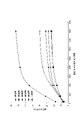
図6に、実施例1~5及び比較例1についての電極の劣化評価の結果を示す。縦軸に電圧上昇値を示し、横軸に通電/停止の繰り返し回数を示す。
Table 2 below shows the measurement results of the voltage rise value (numerical unit is mV) for each number of repetitions for Examples 1 to 5.
In addition, as Comparative Example 1, the measurement results of the voltage rise value when continuous energization and energization stop are repeated without opening and closing all the installed isolation valves are also shown.
FIG. 6 shows the results of electrode deterioration evaluation for Examples 1 to 5 and Comparative Example 1. The vertical axis shows the voltage rise value, and the horizontal axis shows the number of repetitions of energization / stop.

また、表2に示した電圧上昇値について上述の評価基準に従って評価した結果を下記表3に示す。 The results of evaluating the voltage rise values shown in Table 2 according to the above-mentioned evaluation criteria are shown in Table 3 below.
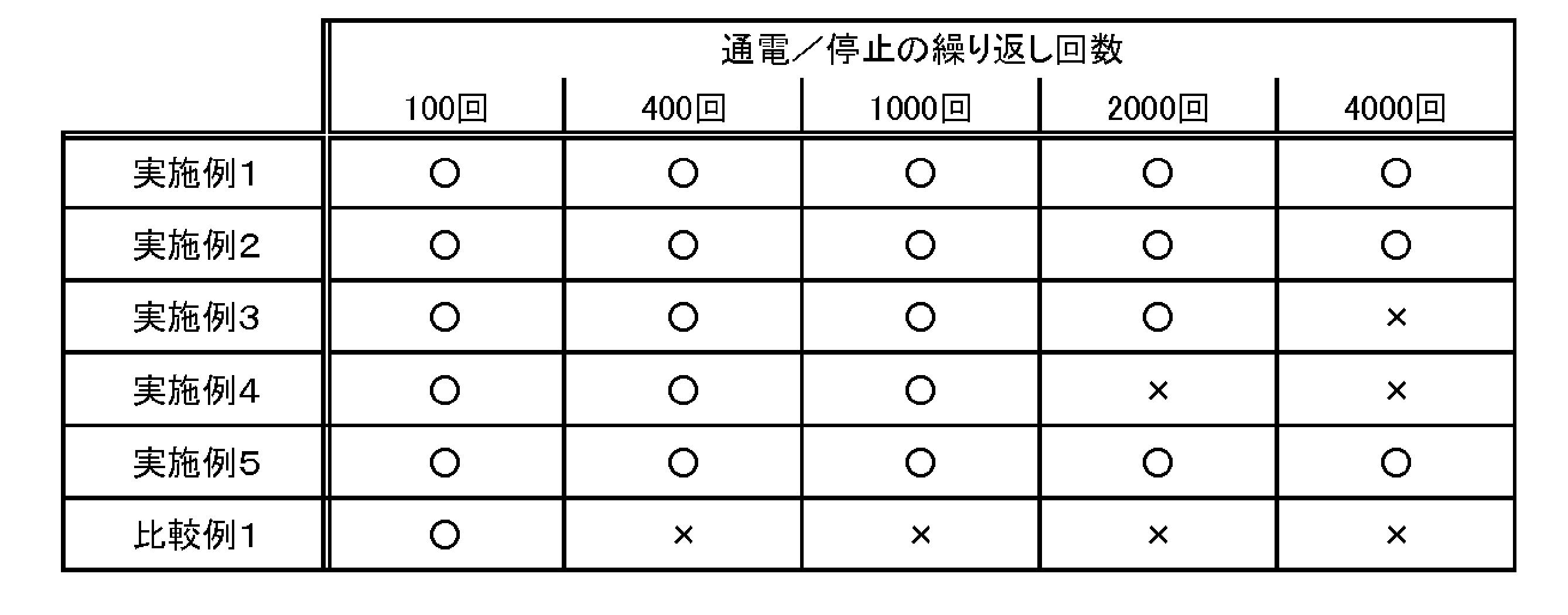
表3に示した通り、比較例1は連続通電と通電停止との繰り返し回数が400回を超えた時点で電極の劣化が認められる結果となった。比較例1は遮断弁を使用していないため、水電解装置の通電/停止の繰り返し運転において、電流遮断弁を開閉する効果は大きいといえる。 As shown in Table 3, in Comparative Example 1, deterioration of the electrode was observed when the number of repetitions of continuous energization and energization stop exceeded 400 times. Since Comparative Example 1 does not use a isolation valve, it can be said that the effect of opening and closing the current isolation valve is great in the repeated operation of energizing / stopping the water electrolyzer.
また、表3より、通電と停止の繰り返し運転を長期に亘り行うと、電流遮断弁を閉とするタイミングを2秒と早めにする方が、60秒と遅めにするよりも、電極の劣化が少ないことがわかる。 In addition, as shown in Table 3, when repeated operation of energization and stop is performed for a long period of time, it is better to close the current isolation valve as early as 2 seconds than to delay it as 60 seconds, and the electrode deteriorates. It turns out that there are few.
本発明によれば、電解停止時に生じる逆電流により、電極が劣化して過電圧が上昇することを抑制することができる。 According to the present invention, it is possible to prevent the electrode from deteriorating and the overvoltage from rising due to the reverse current generated when the electrolysis is stopped.
1 隔壁
2 電極
2a 陽極
2c 陰極
2e 導電性弾性体
2r 集電体
3 外枠
4 隔膜
5 電極室
5a 陽極室
5c 陰極室
5i 電解液入口
5o 電解液出口
5ai 陽極電解液入口
5ao 陽極電解液出口
5ci 陰極電解液入口
5co 陰極電解液出口
6 整流板
6a 陽極整流板(陽極リブ)
6c 陰極整流板(陰極リブ)
7 ガスケット
10 ヘッダー
10I 内部ヘッダー
10O 外部ヘッダー
10Oai 陽極入口ヘッダー(陽極入口側ホース)
10Oao 陽極出口ヘッダー(陽極出口側ホース)
10Oci 陰極入口ヘッダー(陰極入口側ホース)
10Oco 陰極出口ヘッダー(陰極出口側ホース)
20 導管
20Oai 陽極用配液管
20Oao 陽極用集液管
20Oci 陰極用配液管
20Oco 陰極用集液管
50 複極式電解槽
51g ファストヘッド、ルーズヘッド
51a 陽極ターミナルエレメント
51c 陰極ターミナルエレメント
51i 絶縁板
51r タイロッド
60 複極式エレメント
65 電解セル
70 電解装置
71 電解液循環ポンプ
72 気液分離タンク
72h 水素分離タンク
72o 酸素分離タンク
73 水投入ポンプ
74 整流器
75 酸素濃度計
76 水素濃度計
77 流量計
78 圧力計
79 熱交換器
80 圧力制御弁
90 電流遮断弁
D1 隔壁に沿う所与の方向(電解液通過方向)
S1 複極式エレメントの通電面の面積
S2 ヘッダーの流路の断面積
L2 ヘッダーの流路の長さ
Z ゼロギャップ構造
d 電解セルの厚さ
1 partition 2
6c Cathode rectifying plate (cathode rib)
7
10Oao Anode outlet header (anode outlet side hose)
10Oci Cathode inlet header (cathode inlet side hose)
10Oco Cathode outlet header (cathode outlet side hose)
20 Conduit 20Oai Anode liquid collector 20Oao Anode liquid collector 20Oci Cathode liquid collector 20Oco
S1 Area of the current-carrying surface of the multi-pole element S2 Cross-sectional area of the header flow path L2 Header flow path length Z Zero gap structure d Electrolytic cell thickness
Claims (11)
前記流路を遮断可能な電流遮断弁と、
を備え、
前記流路は、前記電極室の入口側の流路及び出口側の流路を含み、
前記電流遮断弁は、前記入口側の流路及び前記出口側の流路それぞれに設けられていることを特徴とする、電解槽。 The electrode chamber and the flow path communicating with the electrode chamber ,
A current isolation valve that can interrupt the flow path,
Equipped with
The flow path includes a flow path on the inlet side and a flow path on the outlet side of the electrode chamber.
The electrolytic cell is characterized in that the current cutoff valve is provided in each of the inlet side flow path and the outlet side flow path .
Priority Applications (1)
| Application Number | Priority Date | Filing Date | Title |
|---|---|---|---|
| JP2018134265A JP7082002B2 (en) | 2018-07-17 | 2018-07-17 | Electrolytic cell and how to use it |
Applications Claiming Priority (1)
| Application Number | Priority Date | Filing Date | Title |
|---|---|---|---|
| JP2018134265A JP7082002B2 (en) | 2018-07-17 | 2018-07-17 | Electrolytic cell and how to use it |
Publications (2)
| Publication Number | Publication Date |
|---|---|
| JP2020012146A JP2020012146A (en) | 2020-01-23 |
| JP7082002B2 true JP7082002B2 (en) | 2022-06-07 |
Family
ID=69170498
Family Applications (1)
| Application Number | Title | Priority Date | Filing Date |
|---|---|---|---|
| JP2018134265A Active JP7082002B2 (en) | 2018-07-17 | 2018-07-17 | Electrolytic cell and how to use it |
Country Status (1)
| Country | Link |
|---|---|
| JP (1) | JP7082002B2 (en) |
Families Citing this family (4)
| Publication number | Priority date | Publication date | Assignee | Title |
|---|---|---|---|---|
| JP7542334B2 (en) * | 2020-06-15 | 2024-08-30 | 旭化成株式会社 | Internal manifold type bipolar water electrolysis element |
| JP7579086B2 (en) * | 2020-08-24 | 2024-11-07 | 旭化成株式会社 | Method for operating electrolysis device and electrolysis system |
| EP4183896A1 (en) * | 2021-11-18 | 2023-05-24 | Industrie De Nora S.P.A. | Electrolysis unit for obtaining gaseous products |
| DK182115B1 (en) * | 2023-11-23 | 2025-08-20 | Green Hydrogen Systems As | Water electrolyser stack having a range of half-cells frames |
Citations (4)
| Publication number | Priority date | Publication date | Assignee | Title |
|---|---|---|---|---|
| JP2014095128A (en) | 2012-11-09 | 2014-05-22 | Asahi Kasei Chemicals Corp | Electrolysis system and electrical insulation method for electrolysis system |
| JP2015120944A (en) | 2013-12-20 | 2015-07-02 | 旭化成株式会社 | Electrolysis cell and electrolysis tank |
| JP2015129344A (en) | 2014-11-06 | 2015-07-16 | 旭化成株式会社 | Electrolysis method |
| US20160194769A1 (en) | 2015-01-06 | 2016-07-07 | Chlorine Engineers Corp., Ltd. | Method of preventing reverse current flow through an ion exchange membrane electrolyzer |
Family Cites Families (1)
| Publication number | Priority date | Publication date | Assignee | Title |
|---|---|---|---|---|
| JPH0217007Y2 (en) * | 1987-05-14 | 1990-05-11 |
-
2018
- 2018-07-17 JP JP2018134265A patent/JP7082002B2/en active Active
Patent Citations (4)
| Publication number | Priority date | Publication date | Assignee | Title |
|---|---|---|---|---|
| JP2014095128A (en) | 2012-11-09 | 2014-05-22 | Asahi Kasei Chemicals Corp | Electrolysis system and electrical insulation method for electrolysis system |
| JP2015120944A (en) | 2013-12-20 | 2015-07-02 | 旭化成株式会社 | Electrolysis cell and electrolysis tank |
| JP2015129344A (en) | 2014-11-06 | 2015-07-16 | 旭化成株式会社 | Electrolysis method |
| US20160194769A1 (en) | 2015-01-06 | 2016-07-07 | Chlorine Engineers Corp., Ltd. | Method of preventing reverse current flow through an ion exchange membrane electrolyzer |
Also Published As
| Publication number | Publication date |
|---|---|
| JP2020012146A (en) | 2020-01-23 |
Similar Documents
| Publication | Publication Date | Title |
|---|---|---|
| JP6912557B2 (en) | Water electrolysis system, water electrolysis method, hydrogen production method | |
| JP6948384B2 (en) | Water electrolysis system, water electrolysis method, hydrogen production method | |
| AU2021398250B2 (en) | Alkaline water electrolysis system, and method for operating alkaline water electrolysis system | |
| JP7082002B2 (en) | Electrolytic cell and how to use it | |
| EP3879006A1 (en) | Method for manufacturing hydrogen | |
| WO2013191140A1 (en) | Bipolar alkaline water electrolysis unit and electrolytic cell | |
| AU2021255398B2 (en) | Electrolysis system and method of using same | |
| AU2019385031B2 (en) | Hydrogen production method | |
| JPWO2020241129A1 (en) | How to operate the electrolyzer | |
| JP6858841B2 (en) | External header type multi-pole element, external header type multi-pole electrolytic cell, and hydrogen production method | |
| JP6803406B2 (en) | Electrolytic cell, electrolyzer, electrolysis method | |
| JP7295704B2 (en) | Method of operating electrolyzer and electrolyzer | |
| JP7470818B2 (en) | Alkaline water electrolysis system and method for operating the alkaline water electrolysis system | |
| JP7542334B2 (en) | Internal manifold type bipolar water electrolysis element | |
| JP7579086B2 (en) | Method for operating electrolysis device and electrolysis system | |
| JP7765497B2 (en) | Internal manifold type bipolar electrolytic element, electrolytic cell, and method for producing hydrogen | |
| JP7269099B2 (en) | Method of operating electrolyzer and electrolyzer | |
| JP2026017230A (en) | Alkaline water electrolysis cell, bipolar alkaline water electrolysis unit, and alkaline water electrolysis cell | |
| CN120138663A (en) | A kind of water electrolysis hydrogen production equipment and method |
Legal Events
| Date | Code | Title | Description |
|---|---|---|---|
| A621 | Written request for application examination |
Free format text: JAPANESE INTERMEDIATE CODE: A621 Effective date: 20210412 |
|
| A131 | Notification of reasons for refusal |
Free format text: JAPANESE INTERMEDIATE CODE: A131 Effective date: 20220201 |
|
| A521 | Request for written amendment filed |
Free format text: JAPANESE INTERMEDIATE CODE: A523 Effective date: 20220330 |
|
| TRDD | Decision of grant or rejection written | ||
| A01 | Written decision to grant a patent or to grant a registration (utility model) |
Free format text: JAPANESE INTERMEDIATE CODE: A01 Effective date: 20220510 |
|
| A61 | First payment of annual fees (during grant procedure) |
Free format text: JAPANESE INTERMEDIATE CODE: A61 Effective date: 20220526 |
|
| R150 | Certificate of patent or registration of utility model |
Ref document number: 7082002 Country of ref document: JP Free format text: JAPANESE INTERMEDIATE CODE: R150 |