JP5877044B2 - Ceiling sheet mounting structure - Google Patents
Ceiling sheet mounting structure Download PDFInfo
- Publication number
- JP5877044B2 JP5877044B2 JP2011259057A JP2011259057A JP5877044B2 JP 5877044 B2 JP5877044 B2 JP 5877044B2 JP 2011259057 A JP2011259057 A JP 2011259057A JP 2011259057 A JP2011259057 A JP 2011259057A JP 5877044 B2 JP5877044 B2 JP 5877044B2
- Authority
- JP
- Japan
- Prior art keywords
- clip
- sheet material
- ceiling sheet
- ceiling
- cover
- Prior art date
- Legal status (The legal status is an assumption and is not a legal conclusion. Google has not performed a legal analysis and makes no representation as to the accuracy of the status listed.)
- Expired - Fee Related
Links
Images


Landscapes
- Connection Of Plates (AREA)
Description
本発明は、建築物における天井シート材の取付構造に関する。 The present invention relates to a mounting structure for a ceiling sheet material in a building.
従来、学校の体育館、教室等やコンサート会場施設等において、既存天井の下方に天井シート材を取り付けて意匠性のある膜天井を形成することが実施されている。膜天井は落ちにくく、かりに落ちても軽量であるため危険性が低いため、近年では一般住宅においても、石膏等を用いた従来の天井に代えて、あるいは従来の天井面の上面に膜天井を施工する例もある。また、膜天井の上方にある天井(構造物)が落下したときに、それを受け止めることができるというメリットもある。 Conventionally, in school gymnasiums, classrooms, concert hall facilities, etc., it has been practiced to attach a ceiling sheet material below an existing ceiling to form a designable membrane ceiling. Membrane ceilings are difficult to fall off, and since they are lightweight even if they fall on a scale, the danger is low.In recent years, instead of conventional ceilings using plaster or the like, membrane ceilings have been installed on top of conventional ceiling surfaces. There is also an example of construction. There is also an advantage that when a ceiling (structure) above the membrane ceiling falls, it can be received.
このような膜天井を形成するための天井シート材は、その周縁を天井廻り縁に固定することで取り付けられる。 The ceiling sheet material for forming such a membrane ceiling is attached by fixing the periphery of the ceiling sheet material to the edge around the ceiling.
特許文献1には、天井シート材の周縁に係止部材を取り付けて、その係止部材を天井廻り縁に設けた係止部に引っ掛けるようにして天井シート材を張設するようにした天井シート材の取付構造が記載されている。
この取付構造によれば、予め、正しい寸法に裁断した天井シート材に係止部材を取り付けておけば、現場での取付作業を迅速に行うことができる。 According to this attachment structure, if the locking member is attached in advance to the ceiling sheet material that has been cut into the correct dimensions, the on-site attachment operation can be performed quickly.
しかしながら、このような係止部材付きの天井シート材は、周縁に係止部材が取り付けてあるから、係止部材を取り付けたままでは天井シート材の寸法を変更することはできない。つまり、寸法誤差のある天井シート材を持ち込んだ場合や、現場で仕様変更が生じた場合、現場で微調整が必要な場合に、天井シート材の寸法を調節することはできない。 However, since the ceiling sheet material with such a locking member has the locking member attached to the periphery, the dimensions of the ceiling sheet material cannot be changed with the locking member attached. That is, when a ceiling sheet material having a dimensional error is brought in, when a specification change occurs on the site, or when fine adjustment is necessary on the site, the size of the ceiling sheet material cannot be adjusted.
本発明は、このような事情を考慮して提案されたもので、その目的は、現場において寸法を自由に調節でき、かつ簡易、迅速に取り付けることができる天井シート材の取付構造を提供することにある。 The present invention has been proposed in view of such circumstances, and an object of the present invention is to provide a ceiling sheet material mounting structure that can be freely adjusted in size and can be easily and quickly mounted on site. It is in.
上記目的を達成するために、請求項1に記載の天井シート材の取付構造は、クリップ本体と、カバークリップとを備え、該クリップ本体で天井シート材を挟着固定するようにした天井シート材の取付構造であって、クリップ本体は、直立基板部と、該直立基板部の上下端から拡開状に延設した上下弾性挟着部とを備えている一方、カバークリップは、内部に没入した前記クリップ本体の上下弾性挟着部を上下より覆うように挟持する上下挟持片を有した凹溝体形状となっており、カバークリップは、内装されたクリップ本体の上下弾性挟着部の弾発力に抗して、上下挟持片で該上下弾性挟着部を上下より押圧挟持し、上下弾性挟着部同士を近接させて天井シート材を挟着固定する構造となっており、クリップ本体の直立基板部の外面には、カバークリップの底部に向かう突起が形成されている一方、カバークリップの内底部には、突起と嵌合する凹部が形成されていることを特徴とする。
To achieve the above object, the ceiling sheet material mounting structure according to
請求項2に記載の天井シート材の取付構造は、上下弾性挟着部が、直立基板部の上下端から拡開状に延設した上下挟着片と、該挟着片の先端を直立基板部の方向へ鋭角的に折り曲げて対向形成した上下押圧爪片とより構成されていることを特徴とする。
The ceiling sheet material mounting structure according to
請求項3に記載の天井シート材の取付構造は、上下押圧爪片の先端部の直立基板部からの距離が相互に異なっていることを特徴とする。 The mounting structure of the ceiling sheet material according to claim 3 is characterized in that the distance from the upright substrate portion of the tip portion of the vertical pressing claw piece is different from each other.
請求項4に記載の天井シート材の取付構造は、上下押圧爪片のすくなくとも一方の表面に、他方の押圧爪片を押圧する押圧凸部が形成されていることを特徴とする。 The mounting structure for the ceiling sheet material according to claim 4 is characterized in that at least one of the upper and lower pressing claw pieces has a pressing projection for pressing the other pressing claw piece.
請求項5に記載の天井シート材の取付構造は、カバークリップの上下挟持片の先端が開口部側に折曲されている一方、クリップ本体の上下弾性挟着部は中央で括れていることを特徴とする。
The attachment structure of the ceiling sheet material according to claim 5 is that the top and bottom clamping pieces of the cover clip are bent to the opening side, while the vertical elastic clamping part of the clip body is constricted at the center. Features.
請求項1に記載の天井シート材の取付構造によれば、カバークリップが、内装されたクリップ本体の上下弾性挟着部の弾発力に抗して、上下挟持片で上下弾性挟着部を上下より押圧挟持する構成となっているため、クリップ本体を天井シート材を挟着した状態で固定保持することができ、天井シート材をしっかりと張設保持することができる。
さらに、請求項1に記載の天井シート材の取付構造によれば、クリップ本体の直立基板部に形成された突起と、カバークリップの内底部に形成された凹部とが嵌合する構造となっているため、クリップ本体のカバークリップ内でのぐらつきを防止することができる。また、カバークリップの凹部を貫通孔で構成すれば、その貫通孔から器具を差し込むことでクリップ本体を押し出すことができる。
According to the ceiling sheet material mounting structure according to
Furthermore, according to the mounting structure of the ceiling sheet material according to
そして、このようにクリップ本体とカバークリップとを操作しながら天井シート材を張設できるので、天井シート材の取り付けを簡易かつ迅速に行える。また、現場で天井シート材の挟着部位を種々変更できるので、施工現場で寸法調節を行うこともできる。 Since the ceiling sheet material can be stretched while operating the clip body and the cover clip in this way, the ceiling sheet material can be easily and quickly attached. Moreover, since the clamping site | part of a ceiling sheet material can be changed variously on the site, a dimension adjustment can also be performed on a construction site.
請求項2に記載の天井シート材の取付構造によれば、弾性挟着部が挟着片と押圧爪片との2片でなるため、押圧爪で天井シート材をしっかりと係止したうえで、挟着片で天井シート材を強力に挟着することができ、そのため落下するおそれはほとんどない。また、天井シート材は押圧爪片でしっかりと係止されるので、挟着後にずれ動くことがない。
According to the mounting structure of the ceiling sheet material according to
請求項3に記載の天井シート材の取付構造によれば、上下押圧爪片の先端部の直立基板部からの距離が相互に異なっているので、上下押圧爪片の先端部同士が重なり合うことがなく、先端の爪同士で天井シート材を傷つけることを防止できる。また、先端部の位置を異ならせているので、天井シート材を折曲状態に固定でき、抜け止め防止に寄与できる。 According to the ceiling sheet material mounting structure according to claim 3, since the distances from the upright substrate portion of the tip portion of the vertical pressing claw piece are different from each other, the tip portions of the vertical pressing claw piece may overlap each other. In addition, it is possible to prevent the ceiling sheet material from being damaged by the nails at the tips. Moreover, since the position of the front-end | tip part is varied, the ceiling sheet | seat material can be fixed to a bending state, and it can contribute to prevention of falling-off.
請求項4に記載の天井シート材の取付構造によれば、押圧爪片のすくなくとも一方の表面に他方の押圧爪片を押圧する押圧凸部が形成されているので、天井シート材を抜けにくくすることができる。 According to the mounting structure of the ceiling sheet material according to claim 4, since at least one surface of the pressing claw piece is formed with a pressing convex portion that presses the other pressing claw piece, it is difficult to remove the ceiling sheet material. be able to.
請求項5に記載の天井シート材の取付構造によれば、カバークリップの上下挟持片の先端が開口部側に折曲されている一方、クリップ本体の上下弾性挟着部は中央で括れているので、クリップ本体が突出状態にあるときでも、カバークリップの上下挟持片の先端がクリップ本体の括れた箇所に係止され得、クリップ本体の全体が抜け外れることを防止できる。
According to the ceiling sheet material mounting structure according to claim 5, the top and bottom clamping pieces of the cover clip are bent at the opening side while the vertical elastic clamping portion of the clip body is constricted at the center. Therefore, even when the clip main body is in the protruding state, the tip of the upper and lower clamping pieces of the cover clip can be locked at the constricted portion of the clip main body, and the entire clip main body can be prevented from coming off.
以下に、本発明の実施の形態について、添付図面を参照しながら説明する。 Embodiments of the present invention will be described below with reference to the accompanying drawings.
図1〜図5は、本発明の一実施形態に係る天井用シート材の取付構造(クリップ本体とカバークリップよりなるシート取付具)の説明図である。 1 to 5 are explanatory views of a ceiling sheet material mounting structure (a sheet mounting tool including a clip body and a cover clip) according to an embodiment of the present invention.
このシート取付具10は、天井2(図5(b)参照)に配設される天井シート材1を張設して取り付ける取付具であり、クリップ本体20と、それを内装するカバークリップ30とより構成されている。
The
クリップ本体20は、カバークリップ30に対して、弾性変形しながら出没し得る構造となっている。
The clip
クリップ本体20は、直立基板部21と、その上下端から、中間で括れ、先端で拡開した状態に延設された上下弾性挟着部22、22とを備えている。
The clip
すなわち、クリップ本体20は、一対の弾性挟着部22、22の中間で括れ、先端に向けて広がった凹溝体として形成されている。
That is, the clip
それぞれの弾性挟着部22は、括れ部22bを有した挟着片22aと、挟着片22aの先端側に位置する挟着動作片22aaを直立基板部21の方向へ折り返すように折り曲げられて延びた押圧爪片22cとよりなる。
Each
押圧爪片22cは、挟着片22aの先端側に位置する挟着動作片22aaにほぼ平行となるように折り曲げられており、挟着動作片22aaのほぼ中間の位置まで延び、押圧爪片22cの先端部と他方の押圧爪片22cの先端部との間にスリット状の開口部23が形成されている。この開口部23に対して天井シート材1の出し入れができるようになっている。
The pressing
後述するように、クリップ本体20がカバークリップ30の開口33より突出しているときは、クリップ本体20は弾性力を有さずに上下挟着動作片22aa、22aaが開いた状態にあり、上下挟着動作片22aa、22aaと上下押圧爪片22c、22cで形成されるハ字状部が、開口部23より挿入される天井シート材1の受入れ部24を構成する。
As will be described later, when the clip
本実施形態では、上下押圧爪片22c、22cはその長さを相互に異ならせて、その先端位置がずれるように構成されている。
In the present embodiment, the upper and lower
また、直立基板部21の外側の高さ方向の中央位置には、長手方向に沿って2つの突起21a、21aが形成されている。
In addition, two
一方、カバークリップ30は、クリップ本体20の開口部23と同方向に開口した凹溝体として形成され、カバークリップ30の開口33が底部31よりもやや窄まった形状となっている。凹溝体の壁部は挟持片32、32を構成しており、内装されたクリップ本体20を上下より押圧挟持する構成となっている。
On the other hand, the
底部31の上下端には、外側にやや突出したリブ31c、31cが形成され、底部31の高さ方向の中央位置には、長手方向に沿って2つの貫通孔31a、31aが形成されている。また、底部31の長手方向の両端には、半円状の切り欠き開口31b、31bが形成されている。
また、上下挟持片32、32の先端はともに開口33側に折曲しているため、クリップ本体20が突出状態にあるときでも、カバークリップ30の上下挟持片32、32の先端がクリップ本体20の括れ部22b、22bに係止され得、クリップ本体20の全体が抜け外れることを防止できる。
Further, since the tips of the upper and
このシート取付具10は、クリップ本体20がカバークリップ30に内装された状態で使用され、図1(a)(b)のように、クリップ本体20のカバークリップ30の開口33からの突出と、カバークリップ30の内部への没入とが自在に行えるようになっている。
The
クリップ本体20は、挟着片22a、22aが弾性を有し、括れ部22b、22bよりも前方部のハ字状をなした挟着動作片22aa、22aaを上下より押圧して扁平にすることが可能となっており、カバークリップ30の開口33より突出状態にあるときには、弾性付勢力が作用しない開いた状態となっている。また、クリップ本体20が没入状態にあるときには、挟着片22a、22a、特に挟着動作片22aa、22aaが大きく弾性変形してカバークリップ30の内側から弾発力が作用した扁平状態となっている。
The clip
つまり、カバークリップ30は、内装されたクリップ本体20の上下挟着片22a、22aの弾発力に抗して、強い弾性力でもって、上下挟持片32、32で上下挟着動作片22aa、22aaを上下より押圧挟持し、上下挟着動作片22aa、22aa同士が近接状態を維持するように作用する。
That is, the
また、カバークリップ30の開口幅が、クリップ本体20の括れ部22b、22bの幅寸法よりも大きく、直立基板部21の高さ寸法よりも小さくなっているため、クリップ本体20が突出状態にあるときでも、括れ部22b、22bよりも前方の挟着動作片22aa、22aaと押圧爪片22c、22cが外部に突出しているが、括れ部22b、22bよりも後方の基部片22ab、22abおよび直立基板部21は飛び出すことはない。
Further, since the opening width of the
ようするに、カバークリップ30の上下挟持片32、32の折曲された先端が、クリップ本体20の上下弾性挟着部22、22の括れ部22b、22bに係止し得る。そのため、クリップ本体20の全体が抜け外れることを防止できる。
In this way, the bent tips of the upper and
なお、クリップ本体20のカバークリップ30への装着は、長手方向の端部よりスライド装着するようにすればよい。
Note that the
天井シート材1は、クリップ本体20が突出状態にあるとき、上下押圧爪片22c、22c間にできる開口部23より内部へと挿入される。この状態では、上下押圧爪片22c、22cが開いてハ字状の受入れ部24を形成しており、この受入れ部24が天井シート材1の挿入のためのガイド部として作用する。
When the clip
そして、クリップ本体20を前方よりカバークリップ30の中に押し込むと、クリップ本体20は突出状態から没入状態へと移行する。その際、上下挟着動作片22aa、22aaおよび上下押圧爪片22c、22cは上下間で近接し、特に上下押圧爪片22c、22cの先端部は天井シート材1を挟んだ状態で弾接状態となる。こうして、天井シート材1を上下押圧爪片22c、22c間に挟み入れた状態で没入させることで、天井シート材1を強力に挟着させることができる(図4参照)。
When the
クリップ本体20がカバークリップ30の内部に完全に没入されると、クリップ本体20の直立基板部21の外面に形成された突起21a、21aが、カバークリップ30の底部31に形成された貫通孔31a、31aにはまり込んだ状態となる。このように、突起21a、21aが貫通孔31a、31aに嵌合するので、クリップ本体20のぐらつきを防止できる。なお、貫通孔31a、31aの代わりに、クリップ本体20の突起21a、21aが滑らない程度の非貫通凹部を設けてもよい。
When the clip
また、天井シート材1をシート取付具10より取り外す場合は、クリップ本体20を突出状態にすればよい。たとえば、カバークリップ30の底部31に貫通孔31aや切り欠き開口31bよりクリップ本体20をラジオペンチ等の器具で押圧して押し出すか、切り欠き開口31bよりクリップ本体20をラジオペンチ等の器具でつまんで横へ引っ張るかすれば、クリップ本体20を容易に取り出すことができる。
Moreover, what is necessary is just to make the clip main body 20 a protrusion state, when removing the
このような天井シート材1の取付構造によれば、カバークリップ30が、内装されたクリップ本体20の上下弾性挟着部22、22の弾発力に抗して、上下挟持片32、32で上下弾性挟着部22、22を上下より押圧挟持する構成となっているため、クリップ本体20を天井シート材1を挟着した状態で固定保持することができ、後述するようにシート取付具10を天井2に固定することで天井シート材1をしっかりと張設保持することができる。
According to such a mounting structure of the
そして、このようにクリップ本体20とカバークリップ30とを操作しながら天井シート材1を張設できるので、天井シート材1の取り付けを簡易かつ迅速に行える。また、現場で天井シート材1の挟着部位を種々変更できるので、予め天井シート材1を正確に寸法に裁断しておく必要はなく、施工現場で寸法調節を行うこともできる。天井シート材1が長い場合でも、折り畳んだ状態でシート取付具10に挟着させることもできる。
Since the
以上のようにして天井シート材1を挟着したシート取付具10は、図5に示すように、天井2の端縁部または天井廻り縁に設けた取付具固定部40に固定される。
As shown in FIG. 5, the
取付具固定部40は、天井2の端縁部に沿って固定される棒状体であり、ボルト、ビス等の固定具で天井に固定される取付片部41と、取付片部41より下方にL字状に延びた固定片部42とより構成される。
The
固定片部42の水平片42aの上面には、長手方向に沿って凹部と凸部が連続する凹凸42aaが形成されている。また、固定片部42の垂直片42bは、その高さ寸法がシート取付具10の幅寸法よりもやや小とされる。
On the upper surface of the
図5(b)に示すように、シート取付具10のカバークリップ30の一方のリブ31cを水平片42aの凹凸42aaの凹部に嵌合させ、そのリブ31cと対角線上に位置する挟持片32の先端を取付片部41の下面に接触させてシート取付具10を垂直片42b側へ傾斜させた状態にすることで、シート取付具10を、抜け出ないように固定することができる。
As shown in FIG. 5 (b), one
ついで、シート取付具10の種々の例について、図6、図7を参照しながら説明する。
Next, various examples of the
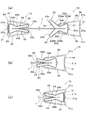
図6は、押圧爪片22cの形状例を示した説明図であり、図6(b)〜(e)には、図6(a)の一点鎖線で示した部位の押圧爪片22c、22cの挟着形状の例を拡大図で示している。
FIG. 6 is an explanatory view showing an example of the shape of the
これらの4例はいずれも、上の押圧爪片22cが下の押圧爪片22cよりも長く形成されているので、天井シート材1を折り曲げた状態に挟着でき、天井シート材1の抜け、外れを防止できる。
In all of these four examples, the upper
図6(b)のものは、一方の押圧爪片22cの先端で他方の押圧爪片22cの表面を押圧する構成となっている。先端同士で押圧する構成ではないため、天井シート材1の破損を防止できる。
6 (b) is configured to press the surface of the other
図6(c)のものは、上下押圧爪片22c、22cの先端を折り曲げて面同士で天井シート材1を挟着できるようにしてある。押圧爪片22c、22cの先端が天井シート材1に当たらないので、天井シート材1の破損を防止できる。
In FIG. 6C, the top and bottom pressing
図6(d)のものは、一方の押圧爪片22cの先端部の表面に押圧凸部22caが形成されており、その押圧凸部22caで他方の押圧爪片22cの表面を押圧する構成となっている。
In FIG. 6D, a pressing projection 22ca is formed on the surface of the tip of one
図6(e)のものは、一方の押圧爪片22cの先端を折り曲げてなる押圧凸部22caが形成されており、その押圧凸部22caが他方の押圧爪片22cの表面に形成した凹部22cbに押圧嵌合する構成となっている。
In FIG. 6E, a pressing convex portion 22ca formed by bending the tip of one
また、図7(a)に示したシート取付具10は、クリップ本体20の括れ部22b、22bがさらに内側に凹んでおり、括れ部22b、22b同士で天井シート材1を挟み込める構成となっている。この構成によれば、上下括れ部22b、22bの挟持により上下押圧爪片22c、22cによる挟着を補完できる。
7A, the constricted
以上の実施形態では、クリップ本体20がカバークリップ30の内部に没入した際には、クリップ本体20の全体が覆われるものを例示したが、没入状態(弾性挟着部が付勢した状態)であっても、図7(b)に示したもののように、クリップ本体20の一部が突出したものであってもよい。
In the above embodiment, when the clip
また、図7(b)に示したシート取付具10のように、クリップ本体20の突出状態にある先端22d、22d(押圧爪片22c、22cの折り曲げ部位)を湾曲形成しておけば、図例のように天井シート材1を張設した場合でも、天井シート材1が破損するおそれはない。
Further, as shown in FIG. 7B, if the
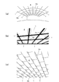
以上に示したシート取付具10による天井シート材1の取付構造は、図8(a)〜(c)に示したような種々の膜天井における天井シート材1の取付固定に使用できる。これらの例は、体育館等への取付例を示したものである。
The mounting structure of the
図8(a)のものは、天井の端部から端部まで(図中の左から右まで)取り付けられる長尺状の天井シート材1であり、長手方向の両端部が天井2の端部に設けたシート取付具10(図1等参照)で固定され、長手辺縁の適所が支持材2aに設けたシート取付具10(図1等参照)で固定される。なお、天井シート材1は、それと交差する支持材2aに吊支持されるようにしてもよい。
The thing of Fig.8 (a) is the elongate
図8(b)のものは、天井が支持材2aにて区切られた矩形エリアに配設される矩形の天井シート材1であり、天井シート材1の四隅が矩形エリアの四隅に設けたシート取付具10(図1等参照)で固定される。
The thing of FIG.8 (b) is the rectangular
図8(c)のものは、天井の端部から端部まで取り付けられる長尺状の天井シート材1であり、長手方向の両端部がシート取付具10(図1等参照)で固定される。なお、長手辺縁はシート取付具10(図1等参照)で支持されず、代わりに天井シート材1の長手方向に直交する方向に配した複数の支持材2aで吊支持するようになっている。
FIG. 8C shows a long
以上には、天井シート材1を天井の下方に吊り下げるように張設する例を示したが、一般住戸の天井にクロスのように貼り付ける場合にも、本シート取付具10の適用は可能である。
In the above, an example in which the
1 天井シート材
2 天井
10 シート取付具
20 クリップ本体
21 直立基板部
21a 突起
22 弾性挟着部
22a 挟着片
22aa 挟着動作片
22ab 基部片
22b 括れ部
22c 押圧爪片
23 開口部
24 受入れ部
30 カバークリップ
31 底部
31a 貫通孔
31b 切り欠き開口
31c リブ
32 挟持片
33 開口
40 取付具固定部
41 取付片部
42 固定片部
DESCRIPTION OF
Claims (5)
前記クリップ本体は、直立基板部と、該直立基板部の上下端から拡開状に延設した上下弾性挟着部とを備えている一方、前記カバークリップは、内部に没入した前記クリップ本体の上下弾性挟着部を上下より覆うように挟持する上下挟持片を有した凹溝体形状となっており、
前記カバークリップは、内装された前記クリップ本体の上下弾性挟着部の弾発力に抗して、前記上下挟持片で該上下弾性挟着部を上下より押圧挟持し、前記上下弾性挟着部同士を近接させて前記天井シート材を挟着固定する構造となっており、
前記クリップ本体の直立基板部の外面には、前記カバークリップの底部に向かう突起が形成されている一方、前記カバークリップの内底部には、前記突起と嵌合する凹部が形成されていることを特徴とする天井シート材の取付構造。 A mounting structure for a ceiling sheet material comprising a clip body and a cover clip, wherein the ceiling sheet material is sandwiched and fixed by the clip body,
The clip body includes an upright substrate portion and an upper and lower elastic sandwiching portion extending from the upper and lower ends of the upright substrate portion, while the cover clip is inserted into the clip body. It has a concave groove shape with upper and lower clamping pieces that clamp the upper and lower elastic clamping parts so as to cover from above and below,
The cover clip presses and holds the upper and lower elastic sandwiched portions from above and below with the upper and lower sandwiching pieces against the elastic force of the vertically elastic sandwiched portion of the clip body incorporated therein, and the upper and lower elastic sandwiched portions. It has a structure in which the ceiling sheet material is clamped and fixed close to each other,
On the outer surface of the upright substrate portion of the clip main body, a protrusion toward the bottom of the cover clip is formed, while on the inner bottom of the cover clip, a recess that fits with the protrusion is formed. A characteristic ceiling sheet material mounting structure.
前記上下弾性挟着部は、前記直立基板部の上下端から拡開状に延設した上下挟着片と、該挟着片の先端を前記直立基板部の方向へ鋭角的に折り曲げて対向形成した上下押圧爪片とより構成されている天井シート材の取付構造。 In claim 1,
The upper and lower elastic sandwiching portions are formed to be opposed to each other by vertically expanding the upper and lower sandwiching pieces extending from the upper and lower ends of the upright substrate portion, and by bending the tip of the sandwiching piece acutely toward the upright substrate portion. The mounting structure of the ceiling sheet material comprised from the up-and-down pressing claw piece.
前記上下押圧爪片の先端部の前記直立基板部からの距離が相互に異なっている天井シート材の取付構造。 In claim 2,
The ceiling sheet material mounting structure in which the distance from the upright substrate portion of the tip portion of the vertical pressing claw piece is different from each other.
前記上下押圧爪片のすくなくとも一方の表面に、他方の押圧爪片を押圧する押圧凸部が形成されている天井シート材の取付構造。 In claim 2 or 3,
A mounting structure for a ceiling sheet material in which a pressing convex portion for pressing the other pressing claw piece is formed on at least one surface of the upper and lower pressing claw piece.
前記カバークリップの上下挟持片の先端が開口部側に折曲されている一方、前記クリップ本体の上下弾性挟着部は中央で括れている天井シート材の取付構造。
In any one of Claims 1-4,
A structure for attaching a ceiling sheet material in which the top and bottom elastic sandwiching portions of the clip main body are constricted at the center while the front ends of the upper and lower clamping pieces of the cover clip are bent toward the opening.
Priority Applications (1)
| Application Number | Priority Date | Filing Date | Title |
|---|---|---|---|
| JP2011259057A JP5877044B2 (en) | 2011-11-28 | 2011-11-28 | Ceiling sheet mounting structure |
Applications Claiming Priority (1)
| Application Number | Priority Date | Filing Date | Title |
|---|---|---|---|
| JP2011259057A JP5877044B2 (en) | 2011-11-28 | 2011-11-28 | Ceiling sheet mounting structure |
Publications (2)
| Publication Number | Publication Date |
|---|---|
| JP2013112969A JP2013112969A (en) | 2013-06-10 |
| JP5877044B2 true JP5877044B2 (en) | 2016-03-02 |
Family
ID=48708775
Family Applications (1)
| Application Number | Title | Priority Date | Filing Date |
|---|---|---|---|
| JP2011259057A Expired - Fee Related JP5877044B2 (en) | 2011-11-28 | 2011-11-28 | Ceiling sheet mounting structure |
Country Status (1)
| Country | Link |
|---|---|
| JP (1) | JP5877044B2 (en) |
Family Cites Families (6)
| Publication number | Priority date | Publication date | Assignee | Title |
|---|---|---|---|---|
| JPS5122504Y2 (en) * | 1971-03-27 | 1976-06-10 | ||
| JP2806114B2 (en) * | 1991-12-17 | 1998-09-30 | 株式会社大林組 | Connection structure of membrane |
| JP2001105773A (en) * | 1999-10-06 | 2001-04-17 | Tokyo Kinzoku Kogyo Kk | Clip |
| JP4772447B2 (en) * | 2005-09-30 | 2011-09-14 | リフォジュール株式会社 | Membrane ceiling structure |
| ES2384653T3 (en) * | 2007-09-06 | 2012-07-10 | Sevastyanova, Alevtina Michaylowna | Tightening binder with a reduced tightening edge beyond a tightening plane |
| FR2926100B1 (en) * | 2008-01-09 | 2010-03-19 | Normalu | SYSTEM FOR ATTACHING WALLS OR CEILINGS TENDUED BY MEANS OF SMALL SIZE |
-
2011
- 2011-11-28 JP JP2011259057A patent/JP5877044B2/en not_active Expired - Fee Related
Also Published As
| Publication number | Publication date |
|---|---|
| JP2013112969A (en) | 2013-06-10 |
Similar Documents
| Publication | Publication Date | Title |
|---|---|---|
| TWI597408B (en) | Clip for perimeter trim | |
| JP5810123B2 (en) | Clip for hanging edge | |
| JP2008066031A (en) | Lamp holder, and lamp holder attachment structure | |
| RU2019129587A (en) | INSTALLATION DEVICE AND WALL STRUCTURE FOR BUILDINGS | |
| JP5877044B2 (en) | Ceiling sheet mounting structure | |
| JP5646096B1 (en) | Wall panel fixing bracket | |
| JP5699071B2 (en) | Ceiling sheet mounting structure | |
| KR200475359Y1 (en) | Stanchion for cable tray | |
| JP2012136899A (en) | Down pipe support implement | |
| JP2009153680A (en) | Plastic frame | |
| JP5967740B1 (en) | Sheet spreading device | |
| KR101062424B1 (en) | Frame for signboard | |
| KR20180003387U (en) | Fixing Bracket of blind | |
| JP6576670B2 (en) | Inspection port device | |
| JP6706073B2 (en) | Inspection device | |
| JP2010038234A (en) | Clip | |
| JP5469139B2 (en) | Lip groove shape connecting device | |
| JP2013083284A (en) | Tube clamp | |
| JP2008048814A (en) | Suspending device | |
| JP4994410B2 (en) | Fitting | |
| JP2005313566A (en) | Binding implement | |
| JP2009058101A (en) | Bracket and fixing device | |
| JP2008045388A (en) | Deck material installing structure | |
| JP4359338B2 (en) | Fitting | |
| JP5707382B2 (en) | 竪 樋 Fixture |
Legal Events
| Date | Code | Title | Description |
|---|---|---|---|
| A621 | Written request for application examination |
Free format text: JAPANESE INTERMEDIATE CODE: A621 Effective date: 20140617 |
|
| A977 | Report on retrieval |
Free format text: JAPANESE INTERMEDIATE CODE: A971007 Effective date: 20150306 |
|
| A131 | Notification of reasons for refusal |
Free format text: JAPANESE INTERMEDIATE CODE: A131 Effective date: 20150317 |
|
| A521 | Written amendment |
Free format text: JAPANESE INTERMEDIATE CODE: A523 Effective date: 20150427 |
|
| A131 | Notification of reasons for refusal |
Free format text: JAPANESE INTERMEDIATE CODE: A131 Effective date: 20150721 |
|
| A521 | Written amendment |
Free format text: JAPANESE INTERMEDIATE CODE: A523 Effective date: 20150826 |
|
| TRDD | Decision of grant or rejection written | ||
| A01 | Written decision to grant a patent or to grant a registration (utility model) |
Free format text: JAPANESE INTERMEDIATE CODE: A01 Effective date: 20160105 |
|
| A61 | First payment of annual fees (during grant procedure) |
Free format text: JAPANESE INTERMEDIATE CODE: A61 Effective date: 20160125 |
|
| R150 | Certificate of patent or registration of utility model |
Ref document number: 5877044 Country of ref document: JP Free format text: JAPANESE INTERMEDIATE CODE: R150 |
|
| LAPS | Cancellation because of no payment of annual fees |