JP5877030B2 - Imaging apparatus and imaging method - Google Patents
Imaging apparatus and imaging method Download PDFInfo
- Publication number
- JP5877030B2 JP5877030B2 JP2011224979A JP2011224979A JP5877030B2 JP 5877030 B2 JP5877030 B2 JP 5877030B2 JP 2011224979 A JP2011224979 A JP 2011224979A JP 2011224979 A JP2011224979 A JP 2011224979A JP 5877030 B2 JP5877030 B2 JP 5877030B2
- Authority
- JP
- Japan
- Prior art keywords
- imaging
- unit
- camera
- display
- subject
- Prior art date
- Legal status (The legal status is an assumption and is not a legal conclusion. Google has not performed a legal analysis and makes no representation as to the accuracy of the status listed.)
- Active
Links
- 238000003384 imaging method Methods 0.000 title claims description 63
- 230000001133 acceleration Effects 0.000 claims description 15
- 238000001514 detection method Methods 0.000 claims description 12
- 238000000034 method Methods 0.000 claims description 11
- 230000005484 gravity Effects 0.000 claims description 7
- 230000000694 effects Effects 0.000 description 9
- 230000003287 optical effect Effects 0.000 description 5
- 238000012545 processing Methods 0.000 description 5
- 238000005286 illumination Methods 0.000 description 4
- 238000004891 communication Methods 0.000 description 3
- 239000000470 constituent Substances 0.000 description 3
- 238000010411 cooking Methods 0.000 description 2
- 238000013461 design Methods 0.000 description 2
- 238000010586 diagram Methods 0.000 description 2
- 230000002349 favourable effect Effects 0.000 description 2
- 238000009432 framing Methods 0.000 description 2
- 239000004973 liquid crystal related substance Substances 0.000 description 2
- 239000002184 metal Substances 0.000 description 2
- 229910052751 metal Inorganic materials 0.000 description 2
- 239000003086 colorant Substances 0.000 description 1
- 238000012937 correction Methods 0.000 description 1
- 230000003760 hair shine Effects 0.000 description 1
- 230000011514 reflex Effects 0.000 description 1
- 230000035945 sensitivity Effects 0.000 description 1
Images


Description
本発明は撮像装置及びカメラ並びに電子機器に関し、より詳細には、所謂、デジタルカメラなどの撮影装置の改良に関するものである。 The present invention relates to an imaging apparatus, a camera, and an electronic apparatus, and more particularly to an improvement of a so-called photographing apparatus such as a digital camera.
近年、デジタルカメラのような撮影装置は、これまで以上の市場普及によって、写真撮影経験のないユーザーにもきれいな写真を撮影できるような工夫が進んでいる。フィルム式のカメラとは異なり、撮影前の画像や撮影後の画像を確認可能で、これらの画像確認用の表示部を有するので、この画面上に様々なインフォーメーションを表示して、ユーザーに分かりやすいガイドや警告を行うことが可能となった。 In recent years, photography apparatuses such as digital cameras have been devised so that users who have no photography experience can take beautiful pictures due to market spread more than ever. Unlike film-type cameras, it is possible to check images before shooting and after shooting, and since it has a display for checking these images, various information is displayed on this screen to make it easy for the user to understand. Easy guides and warnings are now possible.
例えば、下記特許文献1には、ヘルプモードを搭載し、ユーザーが困った時に操作すると上記表示部に指示が出るカメラなどの提案がなされている。 For example, Patent Document 1 below proposes a camera or the like that is equipped with a help mode and that gives instructions to the display unit when operated when a user is in trouble.
しかしながら、撮影者に撮影時の指示が出されても、何が問題であるかが直感的に分からないと、指示をどのように実行して良いかがわからない場合があった。 However, even if the photographer is instructed at the time of shooting, there is a case where it is not possible to know how to execute the instruction unless intuitively knowing what is the problem.
本発明は、このような状況において、ユーザーが特別な操作をすることなく、直感的に撮影状況を理解して、即座に指示に従った撮影が可能な撮影装置、撮影方法を提供するものである。 The present invention provides a photographing apparatus and a photographing method capable of intuitively understanding a photographing situation and immediately photographing according to an instruction without special operation by a user in such a situation. is there.
上記目的を達成するため本発明の一態様に係る撮影装置は、被写体を撮像する撮像部と、表示部と、上記撮像部で得られた画像を記録する記録部とを有する撮影装置において、上記表示部に上記撮像部で得られた撮像結果と共に、上記撮像時における上記被写体と上記撮像部を結ぶ方向の水平に対する傾き情報を合成表示する表示制御部と、を有し、上記撮影装置は、さらに該装置に入射する正反射光を検出し、上記傾き情報は、上記正反射光が検出されたか否かに従って生成されることを特徴とする。 Imaging apparatus according to an embodiment of the present invention for achieving the above object, the imaging apparatus including an imaging unit for imaging a subject, a display unit, and a recording unit for recording the image obtained by the imaging unit, the A display control unit that synthesizes and displays tilt information with respect to the horizontal in the direction connecting the subject and the imaging unit together with the imaging result obtained by the imaging unit on the display unit; further detects regular reflection light incident on the device, the inclination information is characterized in that the specularly reflected light is being of whether they therefore produced was detected.
上記目的を達成するため本発明の他の態様に係る撮影装置は、該装置にかかる重力方向に従った重力加速度情報を検出する検出部を有し、上記傾き情報は、上記重力加速度情報に従って生成されることを特徴とする。 In order to achieve the above object, an imaging apparatus according to another aspect of the present invention includes a detection unit that detects gravity acceleration information according to a direction of gravity applied to the apparatus, and the tilt information is generated according to the gravity acceleration information. It is characterized by being.
上記目的を達成するため本発明の一態様に係る撮影方法は、被写体を撮像部で撮像する撮像ステップと、上記撮像ステップで得られた画像を表示する表示ステップと、上記撮像ステップで得られた画像を記録する記録ステップとを有する撮影方法において、上記撮像部に入射する正反射光を検出し、傾き情報を上記正反射光が検出されたか否かに従って生成するステップと、上記撮像ステップにおける上記被写体と上記撮像部を結ぶ方向の水平に対する傾き情報表示ステップとを具備することを特徴とする。 In order to achieve the above object, an imaging method according to an aspect of the present invention is obtained by an imaging step of imaging a subject with an imaging unit, a display step of displaying an image obtained in the imaging step, and the imaging step. in imaging method and a recording step of recording an image, detects the regular reflection light incident on the imaging unit, and generating tilt information in accordance with whether the specular reflection light is detected, the in the imaging step A tilt information display step with respect to a horizontal direction in a direction connecting the subject and the imaging unit.
本発明によれば、撮影機器の表示部に示された撮影時の問題を示すガイド表示と共に、撮影の効果を画像で確認しながら、好ましい条件での撮影が楽しめる撮影装置や方法を提供することが可能となる。 According to the present invention, it is possible to provide a photographing apparatus and a method for enjoying photographing under favorable conditions while confirming a photographing effect with an image together with a guide display indicating a photographing problem shown on the display unit of the photographing device. Is possible.
以下、図面に従って本発明を適用したカメラを用いて好ましい実施形態について説明する。本発明を一眼カメラに応用した例を第1実施例として、そのブロック図を図1に示す。 Hereinafter, a preferred embodiment will be described using a camera to which the present invention is applied according to the drawings. An example in which the present invention is applied to a single-lens camera is shown as a first embodiment in the form of a block diagram in FIG.
ここでは、撮影装置として、レンズ交換式のカメラを例にして、本発明の一実施例の説明を行う。しかし、レンズ交換式である必要はなく、カメラ付きの携帯電話や、スマートフォンなどに本発明を利用しても問題はない。このようなレンズ交換式のカメラでは、撮影する被写体に応じて、様々なレンズを利用した撮影が行えるので、人物や風景といった一般的な被写体以外の、本発明が主眼としているような身近にあるものをきれいに撮影したいユーザーは、このようなカメラを利用することが多い。 Here, an embodiment of the present invention will be described by taking an interchangeable lens camera as an example of the photographing apparatus. However, it is not necessary to be an interchangeable lens type, and there is no problem even if the present invention is used for a mobile phone with a camera, a smartphone, or the like. Such an interchangeable lens type camera can shoot using various lenses depending on the subject to be photographed, so it is close to the subject of the present invention other than general subjects such as people and landscapes. Users who want to shoot beautiful things often use such a camera.
このようなレンズ交換式のカメラでは、カメラ本体10に、好みのレンズ20を取り付けて、被写体像を撮像部2に導いて撮影するものだが、レンズ20側には、ズームレンズの場合、複数のレンズ要素の位置を切り換えてズーム制御をするためのズーム制御部26a、ピント合わせ用レンズを動かして、被写体にピントが合うような位置制御するピント制御部、さらには、取込む被写体像の明るさを制御するための絞り制御部26c等を有する。
In such a lens-interchangeable camera, a desired
これらのレンズや絞り制御の位置は、位置判定部25a、25bなどで判定しながら、制御部21が、記録部27に記録された制御データやプログラムによって、モーターなどの駆動部24a、24bを介して制御するものである。レンズリングなどの操作部23によって、マニュアル調整できるようにした機種も多く、ズーム位置(画角)のみならず、ピント位置や絞りによるぼかし効果にこだわりを持った操作を可能としている。
While these lens and aperture control positions are determined by the position determination units 25a and 25b, the
一方、カメラ本体側にも、スイッチ等、ユーザーが様々な操作を行える操作部6がある。撮影装置で重要なのが撮影時の操作なので、静止画撮影用のレリーズボタンなどが右手の人差し指で操作できる位置に優先的に配置されている。 On the other hand, on the camera body side, there is an operation unit 6 such as a switch that allows the user to perform various operations. Since an important operation of the photographing apparatus is an operation at the time of photographing, a release button for photographing a still image is preferentially arranged at a position where it can be operated with the index finger of the right hand.
これらを利用して、撮影操作が可能であるし、その他のスイッチやダイヤルなどを利用して、上記露出補正やシャッタースピードや感度設定、ピント位置の変更など撮影パラメータ変更も可能である。また、タッチパネルもこのような操作を補助して利用できる。 Using these, shooting operations can be performed, and using other switches, dials, and the like, it is also possible to change shooting parameters such as exposure correction, shutter speed and sensitivity setting, and focus position change. A touch panel can also be used by assisting such operations.
カメラ10はさらに交換レンズから入った像を電気信号に変える撮像部2と、撮像結果を表示する部分(接眼表示部30や、背面パネルの表示部8など)に画像を表示したり、撮影時には、記録部4に画像を記録したりする。こうした一連の制御は、マイコン等の集積回路等からなる制御部1が、記録部4に記録されたプログラムに従って行うが、この集積回路には、上記表示や記録に必要な画像処理が可能な信号処理回路も形成されている。
The
また、撮像部2からの画像信号を用いて、被写体の顔部を検出する顔検出部3があり、このような重要画像部位のコントラストや位相差信号からピントのずれを検出したり、露出量など調整量を切り換えたりする撮影制御を行う。接眼表示部は、小型の液晶パネルや有機ELパネル等の表示画像を専用の光学系で拡大して目視可能にするもので、ファインダを覗き込む形で観察可能なので、外光の影響を受けずに画像が確認できる上、この光学系の視度調整によって、ユーザーの視度に合わせて良好な観察を可能とする。さて、これらの調整量は制御部1内のパラメータ制御部(図示せず)によって、切り換え制御が可能である。
In addition, there is a
ユーザーが接眼表示部30や背面パネルなどによる表示部8を見ながら撮影できるように、制御部に組み込まれた信号処理部1は撮像結果を液晶やELパネルなどからなる表示部8に表示できるように処理したりする。この表示部8上にはタッチパネル8bが形成されていて、表示された被写体像を表示部上でタッチすれば、その位置に応じた画像の情報が取得可能である。
The signal processing unit 1 incorporated in the control unit can display the imaging result on the
これは相当する部分の画像の特徴を解析したり、距離情報を検出するものである。また制御部1は、ユーザーの撮影指示操作を操作判定部6(前述の静止画用レリーズボタンや動画用レリーズボタン)やタッチパネル8bで判定して、撮影画像を信号処理部で圧縮して記録部4に記録する。この時、撮影日時情報を合わせて記録して整理できるように時計9がある。
This is to analyze the feature of the image of the corresponding part or to detect distance information. Further, the control unit 1 determines the user's shooting instruction operation with the operation determination unit 6 (the above-described still image release button or moving image release button) or the touch panel 8b, and compresses the shot image with the signal processing unit to record the image. Record in 4. At this time, there is a
また、パラメータ変更の操作によって、画像がどのように変わるかが接眼表示部30や背面パネルの表示部8にて確認できることは言うまでもない。操作時には、撮像結果を表示する部分(接眼表示部30や、背面パネルの表示部8など)に後述するような補助表示が出るが、これは表示制御部1dが被写体像の上に合成表示する。
Needless to say, how the image is changed by the parameter changing operation can be confirmed by the
また、加速度センサ13が設けられており、この出力から制御部1の角度検出部1bがカメラの姿勢などを判定することが可能となっている。また、制御部1内の動き検出部1cは、この加速度センサの出力を利用したり、画像の時間変化でカメラの動きを検出したりする。また、カメラの姿勢や角度が悪い場合に被写体から照明光の正反射光が入ったことを、撮像部2の出力から判定するのが、反射判定部1eである。
Moreover, the
この発明では、カメラが被写体を見込む角度を、ユーザーに意識させて、きれいな写真を撮影できるようにした撮影機器を提供する。こうした見栄え良い写真は、自分だけで楽しむ写真よりも、インターネットなどを利用してみんなに見せる写真において、非常に重要である。持っているものを自慢するような場合においても、いらなくなったものを売ってしまいたいオークションなどでも、見栄えは非常に重要になる。 According to the present invention, there is provided a photographing device that allows a user to be aware of an angle at which a camera looks at a subject and photograph a beautiful photograph. Such nice-looking photos are much more important in photos that you can show to everyone using the Internet than photos that you enjoy yourself. Even if you're proud of what you have, even in an auction where you want to sell what you don't need, the look is very important.
ここでは、一例として、正反射光による「てかり」の問題について説明する。
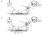
図2(a)のように、例えば、本やLP、CDなどの被写体12を撮影する場合、照明用光源30が多くの場合、天井など上方にある関係から、これら被写体を図のΘ1のような角度で照らすような位置となる場合がある。この時、撮影者11が、図のようにこの被写体12にカメラ10を向けて、図のように水平からΘ2のような角度から撮影しようとするような状況もよくある。
Here, as an example, the problem of “lighting” due to specularly reflected light will be described.
As shown in FIG. 2A, for example, when photographing a
もし、前述の光源と被写体の角度Θ1が、被写体とカメラの角度Θ2と近い値である場合、被写体12の光沢面に照明30からの光が反射して、被写体が光って、その表面の印刷や模様やデザインや写真などの色彩や質感が正しく撮影されない。
If the angle Θ1 between the light source and the subject is close to the angle Θ2 between the subject and the camera, the light from the
多くのユーザーは、机や台の上に、こうした被写体、またアクセサリーなど光沢のある被写体を置いて撮影するので、撮影前や撮影後に、撮像結果を表示する表示部8を見ながら、このような状態になっていることに気付き、思った通りの写真が撮影できないことに気づくような事が起こりえた。
Many users shoot with these subjects and glossy subjects such as accessories placed on a desk or table, so it is important to look at the
そして、何が起こっているかも分からないままに、その状態を対策することなく失敗写真を撮影してしまう事も多かった。本発明では、このような状況においては、カメラを構える角度によって正反射光が来ている事をユーザーに告知して、こうした失敗を防止するようにした。なお、カメラの撮影方向と水平方向のなす角度Θ2は、図1の1bの角度検出部で判定することが出来る。 And without knowing what was happening, I often took a failed photo without taking measures against the situation. In the present invention, in such a situation, the user is notified that the specularly reflected light is coming according to the angle at which the camera is held, so as to prevent such a failure. The angle Θ2 formed by the camera photographing direction and the horizontal direction can be determined by the angle detection unit 1b in FIG.
LPやCDや書籍などは、書かれた文字が読めるような角度から撮影したいので、図2のように寝かして撮影する場合、撮影時に上方から光の影響を受けやすい。また、こうした被写体は、左右対称に撮影したいなどの要望があることから、カメラと被写体の位置関係は、画面の横方向を水平方向と合わせて撮影することが多い。 Since LPs, CDs, books, and the like are desired to be photographed from an angle at which written characters can be read, when taking a picture while lying down as shown in FIG. 2, they are easily affected by light from above during photographing. In addition, since there is a demand for such subjects to be photographed symmetrically, the positional relationship between the camera and the subject is often photographed with the horizontal direction of the screen aligned with the horizontal direction.
この場合、カメラの画面縦方向は被写体の上下方向(文字の上下方向)と合わせてフレーミングされ、撮影光軸方向が、水平に対し、図2のようにΘ2の角度をなし、これを変更するようなフレーミングにて、被写体を狙うことが多い。従って、Y1として示した方向にカメラを動かすことが多い。 In this case, the vertical direction of the camera screen is framed together with the vertical direction of the subject (the vertical direction of the characters), and the photographing optical axis direction forms an angle Θ2 with respect to the horizontal as shown in FIG. Often, the subject is aimed at such framing. Therefore, the camera is often moved in the direction indicated as Y1.
図2(b)のように、カメラ10をY1だけずらして撮影しようとしても、被写体12の幅(図中X0)が、X0=Y1sinΘ2以上である場合、このΘ1≒Θ2の関係は変わらないので、この正反射光は、カメラの画面の同じ位置に入射する。このような関係を用いて、正反射光が来ていることを検出することが出来る。もちろん、単純に、集中して光源特有の色成分の光が入射する場合も、このような正反射状態と判定することが出来る。
Even if the
このようなY1の動きは、カメラがユーザーに指示しても良いが、ユーザーは正反射を避けようと、カメラを無意識に動かすので、図1の1cの動き検出部が、その時の動きを判定して、同時に画像の変化をモニタすれば、反射判定部1eが、正反射光が来ているかどうかを判定することが出来る。カメラの撮像部で正反射光が検出された場合、カメラの傾きΘ2が正反射光のカメラへの入射方向と考えることが出来る。また、それは、被写体12に対して光源30から図中Θ1の角度で入射した光の成分であることも分かる。
Such a movement of Y1 may be instructed by the camera to the user, but since the user moves the camera unconsciously to avoid regular reflection, the movement detection unit 1c in FIG. 1 determines the movement at that time. If the change in the image is monitored at the same time, the reflection determination unit 1e can determine whether or not regular reflection light is coming. When regular reflection light is detected by the imaging unit of the camera, the tilt Θ2 of the camera can be considered as the incident direction of the regular reflection light to the camera. It can also be seen that it is a component of light incident on the subject 12 from the
ここでは、単純化して、机や台の上に、平らな被写体を平らに置いた例を示したが、これらが角度を持って置かれた場合でも、以上のような角度の関係が満たされれば、同様の問題が生じることは言うまでもない。 Here, a simple example is shown in which a flat subject is placed flat on a desk or table. However, even when these are placed at an angle, the above angle relationship is satisfied. Needless to say, similar problems arise.
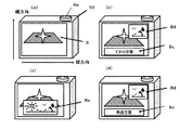
図3はカメラを背面から見たところを図示したもので、ここで上下方向(画面縦方向)と、左右方向(画面横方向)が、どちらの方向のことであるかを示しておく。 FIG. 3 illustrates the camera viewed from the back, and here, it indicates which direction is the vertical direction (vertical direction of the screen) and the horizontal direction (horizontal direction of the screen).
このカメラ10の上面にはレリーズスイッチ6aが設けられており、背面には表示部8が設けられている。このようなカメラ10において、図3(a)のような正反射光(分かりやすい言葉で、「てかり」)を検出した場合、図2(b)のようにカメラを動かした時、画面内の画像は位置が変化するのに、強い光の位置が変わらない場合、正反射光が入って来ているとして、図3(b)のように、正反射光が入っている事を示す警告表示8cや、カメラの角度によって起こっている旨の表示8dを行うようにして、ユーザーに注意を促す。
A release switch 6a is provided on the top surface of the
また、カメラの角度のみならず、光源との位置関係である旨を示す表示8eを、図3(c)のように画面8上に合成表示してもよい。このような角度表示によって、無意識に構えていたカメラが、現在、どのような状況で撮影に使われているかを判断することが可能となる。
Further, not only the camera angle but also the display 8e indicating the positional relationship with the light source may be synthesized and displayed on the
つまり、このような状況説明的なガイドがないと、ユーザーには不快なてかり現象だけが気になって、どのような撮影を行えば、それを対策できるのかまでは理解することが出来なかった。 In other words, if there is no guide to explain the situation like this, the user is only worried about the unpleasant phenomenon, and it is impossible to understand what kind of shooting can be taken to prevent it. It was.
また、図3(d)のように、直接的に角度を変えるように指示したり、推測できる推奨角度を表示するようにしても良い。なお、このような表示が常に表示されるのが邪魔な場合も考えられるので、レンズ部の操作部材23などが操作された場合に、数秒間だけ表示されるような表示制御を行ってもよい。
Further, as shown in FIG. 3D, an instruction to directly change the angle may be given, or a recommended angle that can be estimated may be displayed. In addition, since it may be a hindrance that such a display is always displayed, display control may be performed so that only a few seconds are displayed when the
このように、撮影機器の表示部8(接眼表示部でもよい)に示された撮影時の問題(ここでは「てかり」が起こった理由)を示す角度に関するガイド表示と共に、撮影の効果をライブビュー画像で確認しながら、思い通りの撮影が楽しめる撮影装置や方法を提供することが可能となる。 In this way, the effect of the shooting is displayed together with the guide display regarding the angle indicating the problem at the time of shooting (here, the reason why “tekari” has occurred) shown on the display unit 8 (or the eyepiece display unit) of the imaging device. It is possible to provide a photographing apparatus and method that allows the user to enjoy photographing as desired while checking with a view image.
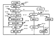
このように、カメラ(撮影装置)の撮影光軸方向(被写体と上記撮像部を結ぶ方向)の水平に対する傾きの警告、またはガイド、あるいはアドバイス表示を設けたカメラのメインフロー例を図4に示す。これは、カメラの制御部1が、記録部に記録されている予め決められたプログラムに従って実行する制御をフローチャートとして表現したものである。 FIG. 4 shows an example of the main flow of the camera provided with the warning of the tilt in the direction of the optical axis of the camera (photographing device) (the direction connecting the subject and the imaging unit), the guide, or the advice display. . This is a flowchart representing the control executed by the control unit 1 of the camera in accordance with a predetermined program recorded in the recording unit.
ここでは、特に、正反射光(てかり)を判定した時に、カメラの角度の変更を促す表示(図3(b)、(c)参照)を可能としたカメラのメインフローの例である。 This is an example of the main flow of the camera that enables display (see FIGS. 3B and 3C) that prompts the change of the camera angle particularly when the specularly reflected light (tekari) is determined.
例えば電源スイッチ(図示せず)などによってなされる電源の操作をステップS101で判定、これがオンされていれば、撮影モードか再生モードかの判定をS102、S111にて行う。電源スイッチがオフされれば、この電源スイッチを検出する回路のみを作動させ、その他の電子回路をオフして省エネモード(スタンバイモード)になる。 For example, a power operation performed by a power switch (not shown) or the like is determined in step S101. If it is turned on, it is determined in S102 and S111 whether the mode is a shooting mode or a playback mode. When the power switch is turned off, only the circuit for detecting the power switch is operated, and the other electronic circuits are turned off to enter the energy saving mode (standby mode).
タッチパネルやスイッチの切り換えで撮影モードに設定されていれば、S103でスルー画表示を行う。これは、撮像部で得られた被写体像信号をリアルタイムに表示部に表示するもので、ユーザーはこれを見ながら撮影タイミングや構図ならびに撮影パラメータ変更の効果を確認することができる。 If the shooting mode is set by switching the touch panel or the switch, a through image is displayed in S103. In this case, the subject image signal obtained by the imaging unit is displayed on the display unit in real time, and the user can check the shooting timing, composition, and effect of changing the shooting parameter while watching this.
S104は後述するユーザーに対して傾き警告をするかどうかを判定(正反射判定など)するためのサブルーチン(図5参照)であり、S105は、傾き表示警告のサブルーチン(図6参照)である。これらのサブルーチンによって、図3で説明したような撮影前に正反射光を受けない撮影を促す表示制御が可能となる。 S104 is a subroutine (see FIG. 5) for determining whether or not to give a tilt warning to the user (described later) (see FIG. 5), and S105 is a tilt display warning subroutine (see FIG. 6). With these subroutines, display control for urging shooting without receiving regular reflection light before shooting as described with reference to FIG. 3 becomes possible.
表示部でスルー画によって効果を確認しながら静止画レリーズスイッチ6aを操作すれば、S106をYに分岐、S107で、正反射による「てかり」を抑えた撮影が可能となる。撮影が行われない場合は、スルー画表示(S103)などから繰り返すので、任意のタイミングにてパラメータ変更や撮影が可能となる。また、再生モードへの切り換えが行われると、S102をS111に分岐し、撮影された画像の再生が行われる(S112)。別の画像を鑑賞したい場合は、ユーザーがやはりタッチパネルやスイッチを操作すると、それをS113で判定し、画像の切り換えをS115で行う。 If the still image release switch 6a is operated while confirming the effect with the through image on the display unit, S106 is branched to Y, and in S107, it is possible to perform photographing while suppressing “light” due to regular reflection. When shooting is not performed, the process is repeated from the through image display (S103) and the like, so that parameter change and shooting can be performed at an arbitrary timing. When switching to the playback mode is performed, S102 is branched to S111, and the captured image is played back (S112). If the user wants to view another image, when the user again operates the touch panel or switch, it is determined in S113, and the image is switched in S115.
また、撮影モードでも再生モードでもない場合は、S114に分岐して外部に撮影画像を送信するような画像通信モードになる。 If neither the shooting mode nor the playback mode is selected, the image communication mode is set such that the process branches to S114 to transmit the shot image to the outside.
このモードは、インターネット上に撮影画像を公開するような場合に有効である。お気に入りの小物をみんなに紹介したり、いらなくなった本やCDなどをネットオークションにかける時にも有効活用できる。このようなユースシーンでは、特に、見栄え良く被写体を撮影する必要があり、本発明のような工夫によって、ユーザーに見栄え良い写真を撮影させる事は、非常に意義深い。 This mode is effective when a photographed image is made public on the Internet. It can also be used effectively to introduce your favorite small items to everyone, or to use books and CDs that you no longer need for online auctions. In such a use scene, it is particularly necessary to shoot a subject with good appearance, and it is very significant to let a user take a good-looking photograph with a device like the present invention.
図5に、図4のS104に示した、傾き警告必要判定のフローを詳しく説明するためのフロー例を示す。 FIG. 5 shows a flow example for explaining in detail the flow of determination of necessity of tilt warning shown in S104 of FIG.
ここでは、すでに説明したとおり、画面内に照明光特有の白色に近い色の強い光線が入って来ている場合、S201でこれを撮像部の出力の像パターンから判定する。このようなパターンが判定された場合、S201をYに分岐して、S202でその強い光のパターンの位置を記録、S203でそれ以外の部分の画像を記録する。 Here, as already described, when a strong light beam having a color close to white, which is peculiar to illumination light, enters the screen, this is determined from the image pattern of the output of the imaging unit in S201. If such a pattern is determined, the process branches from S201 to Y, the position of the strong light pattern is recorded in S202, and the image of the other part is recorded in S203.
これは、図2(b)にて、説明したように、正反射光は、特に平面状の被写体を撮影する場合、手ぶれや構図変更などで、ユーザーがカメラを動かした時も、その入射位置を変えない特性があることを利用して、正反射光を検出するためのものである。 As described in FIG. 2B, this is because the specularly reflected light is incident even when the user moves the camera due to camera shake or composition change, particularly when shooting a planar subject. This is for detecting specularly reflected light by utilizing the characteristic that does not change the light intensity.
つまり、S204で、S203で記録しておいた画像が画面内で時間的にどんな変化をしたかを判定し、移動があった場合は、ユーザーが、カメラを動かしたと判定し、この場合、S204をYに分岐し、S201で検出され、S202で記録されていた強い光の位置の変化があったかどうかを判定する。 That is, in S204, it is determined how the image recorded in S203 has changed over time in the screen. If there is a movement, it is determined that the user has moved the camera. Is branched to Y, and it is determined whether or not there has been a change in the position of the strong light detected in S201 and recorded in S202.
この時、S205をYに分岐した場合は、カメラの傾きによって被写体から正反射光が入っていると考えられ、傾きを変えることによって対策できることを示唆する傾き警告必要と判定する。 At this time, if S205 is branched to Y, it is considered that specular reflection light has entered from the subject due to the tilt of the camera, and it is determined that a tilt warning is necessary, suggesting that countermeasures can be taken by changing the tilt.
これらの条件を満たさない場合は、S211に分岐して傾き判定をしないようにする。ここには、特に記載していないが、このような状況は、図2のような状況下で起こるので、例えば、図1の顔検出機能3などを使って、被写体が何であるかを判定して、必要ない場合には、図5のような判定をしないようにしてもよい。
If these conditions are not satisfied, the process branches to S211 so that the inclination is not determined. Although not specifically described here, such a situation occurs under the situation as shown in FIG. 2. For example, the
図6は、図4のステップS105で実行される傾き警告表示のフローチャート例である。 FIG. 6 is a flowchart example of the tilt warning display executed in step S105 of FIG.
ここでは、傾き判定が有効で、図3(b)、(c)のような表示を行う時の制御を詳しく説明している。S231で、傾き警告が必要とされているかを判定し、必要な場合にはS232で図1の加速度センサ13を作動させ、カメラの横、縦、被写体方向(後述のX、Y、Z)の方向にかかる重力加速度を判定する。
Here, the control when the tilt determination is effective and the display as shown in FIGS. 3B and 3C is performed will be described in detail. In S231, it is determined whether a tilt warning is required. If necessary, the
設計によっては、ここで、図5のS204の代わりにカメラの動きを加速度から判定してもよい。S233でカメラ横方向(X方向)に重力加速度が検出されない場合、図2のようにユーザーがカメラを構えている状態だと判定できる。 Depending on the design, the movement of the camera may be determined from the acceleration instead of S204 in FIG. If no gravitational acceleration is detected in the lateral direction (X direction) of the camera in S233, it can be determined that the user is holding the camera as shown in FIG.
このような状況で、S234とS235でカメラの縦方向、被写体方向(YとZの方向)にかかる加速度(Yg、Zg)を判定し、S236で、これらの結果から、図2で示したΘ2の値をΘとして算出する。前述のように、LPやCDや書籍などは、書かれた文字が読めるような角度から(つまり、上下をカメラ画面の上下に合わせ、どちらかと言えば下から)撮影したい。 In such a situation, accelerations (Yg, Zg) in the camera vertical direction and subject direction (Y and Z directions) are determined in S234 and S235, and in S236, from these results, Θ2 shown in FIG. Is calculated as Θ. As described above, LPs, CDs, books, and the like are desired to be photographed from an angle at which written characters can be read (that is, the top and bottom are aligned with the top and bottom of the camera screen, if anything).
このような状況では、図2のように撮影光軸方向が、水平に対し、図2のようにΘ2の角度をなし、これを変更するようなフレーミングにて、被写体を狙うことが多い。従って、図6のような条件で、こうした撮影状況であることを判定することも出来る。 In such a situation, the direction of the photographic optical axis as shown in FIG. 2 makes an angle of Θ2 as shown in FIG. 2 with respect to the horizontal, and the subject is often aimed by framing that changes this. Accordingly, it is possible to determine that such a shooting situation is present under the conditions shown in FIG.
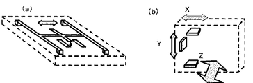
以上の実施例で説明した加速度センサは、具体的には、図7(a)のように、架橋された金属部が、チップ表面の金属部との位置が、加速度によって変化する構造になっている素子であることが多く、カメラの姿勢を変えると、重力のかかり具合で、この架橋部がたわんで変化し、容量成分が変化するため、電気的な出力信号が変化する。 Specifically, the acceleration sensor described in the above embodiments has a structure in which the position of the cross-linked metal part and the metal part on the chip surface changes depending on the acceleration, as shown in FIG. If the posture of the camera is changed, this bridging portion will bend and change due to the degree of gravity, and the capacitance component will change, so the electrical output signal will change.
また、カメラを動かすと、そのときの信号で、どちらの方向に動かされたかが分かる。つまり機器の移動が分かる。 In addition, when the camera is moved, the direction of movement can be determined from the signal at that time. In other words, the movement of the device is known.
上下(Y方向)に動かされたか、左右(X方向)に動かされたか、前後方向(Z方向)を検出できるように、図7(b)のように、カメラ内に加速度センサを、検出方向を変えて、3つ配置すれば良いが、ワンパッケージになったものも多く製品化されている。 As shown in FIG. 7B, an acceleration sensor is installed in the detection direction so that it can be detected whether it is moved up and down (Y direction), left and right (X direction), or front and rear direction (Z direction). However, there are many products that come in one package.
このようにカメラの撮影画面の横方向をX、画面の縦に対応する方向をYとし、それらと直交する方向をZ方向としている。 Thus, the horizontal direction of the camera screen is X, the direction corresponding to the vertical direction of the screen is Y, and the direction perpendicular to them is the Z direction.
以上説明したように、本実施例によれば、撮影機器の表示部に示された撮影時のてかり問題が起こった事をユーザーに認知させ、その問題の原因を示すガイド表示を出すことで、ユーザーが問題解決することの手助けをしつつ、撮影角度変更の効果はライブビュー画像で確認しながら、被写体を正しく描写した撮影が楽しめる撮影装置や方法を提供することが可能となる。 As described above, according to the present embodiment, the user can recognize that a shooting problem has occurred and the guide display indicating the cause of the problem is displayed. Thus, it is possible to provide a photographing apparatus and method that can help a user solve a problem and enjoy photographing while correctly depicting a subject while confirming an effect of changing a photographing angle with a live view image.
ここでは、カメラの撮影方向の角度を変えるような対策の記載をしたが、このような原理表示によって、被写体を立てかけるなどの対策をユーザーが考え出せるような効果も持つことは言うまでもない。 Although the countermeasures for changing the angle of the shooting direction of the camera have been described here, it goes without saying that such a principle display has an effect that allows the user to come up with a countermeasure such as leaning on the subject.
これまでの警告表示やガイド表示には欠如していた具体性で、撮影者を補助することが可能となる。 It is possible to assist the photographer with the concreteness that has been lacking in the conventional warning display and guide display.
このような構成のカメラでは、特に、正反射光を対策しない場合にも撮影角度警告、またはガイド機能を有効に利用することが出来る(第2実施例)。 In the camera having such a configuration, the shooting angle warning or the guide function can be effectively used even when the specular reflection light is not taken into account (second embodiment).
例えば、図8のように、料理を撮影する場合にも、斜め45°からの撮影が有効であるというノウハウが知られている。このようなノウハウを知らずに撮影すると、せっかくの料理のおいしさを引き出した写真とならない場合があった。また、こうしたノウハウを知っている人ばかりのサイトなどに投稿された場合など、自分の写したものだけが見栄えが良くないといった問題となることがあった。 For example, as shown in FIG. 8, know-how that photographing from an angle of 45 ° is effective also when photographing a dish is known. If you shoot without knowing this kind of know-how, it might not be a photo that brought out the great taste of cooking. In addition, when posted on a site only for people who know this know-how, there was a problem that only what was copied was not good looking.
このような状況でも、傾き表示警告はユーザーにとって有効なので、図9のようなフローチャートで、S104bのタイミングにおいて、ユーザーが設定したモードによって、警告を出すようにした。 Even in such a situation, since the tilt display warning is effective for the user, the warning is issued according to the mode set by the user at the timing of S104b in the flowchart as shown in FIG.
このフローチャートの各ステップの説明は、図4と重複するもので、ここでは省略する。ここで想定しているモードは、料理撮影モードや、アクセサリー撮影モードで、図8のΘに示したような傾きを変えて撮影することで、プロ写真家が普通に使っていて、一般ユーザーが知らなかったノウハウに従った撮影が可能になる。この時、表示部に推奨角度を合わせて表示すれば良い。 The description of each step in this flowchart is the same as in FIG. 4 and is omitted here. The modes assumed here are cooking shooting mode and accessory shooting mode. By shooting with different inclinations as shown in Θ in FIG. Shooting according to the know-how you did not know becomes possible. At this time, the recommended angle may be displayed on the display unit.
また、コレクターが同じようなものを撮影する場合にも、例えば、コレクション撮影モードなどで、この表示が出るようにすれば、1つ1つのアイテムを、同じ角度に揃えて撮影し、統一感を出すことが可能になる。例えば、同じような腕時計を撮影して紹介したい場合など、同じ角度から撮ったように統一されていないと、いかにも素人が気まぐれに撮ったように見えて、コレクション自体へのこだわりも疑われてしまう。このような用途では、写真の見栄えが大変、重要になる。 Also, even when the collector is shooting something similar, for example, if this display is displayed in the collection shooting mode, etc., each item will be shot at the same angle to create a sense of unity. It becomes possible to put out. For example, if you want to shoot a similar wristwatch and introduce it, if it is not unified as if it was taken from the same angle, it seems that the amateur took a whim and it seems doubtful about the collection itself . In such applications, the appearance of photographs is very important.
以上説明したように、第2実施例の発明によれば、正反射光の影響とは無関係なシーンにおいても、常に、撮影条件を揃えた撮影を行うことによって、撮影画像間に統一感を持たせるような効果を有するカメラを提供することが出来る。必要なシーンにおいてだけ出て来る表示となっており、構図調節や、シャッターチャンスを逃すようなことはなく、問題になりそうな状況であることを判定して表示制御される。 As described above, according to the invention of the second embodiment, even in a scene irrelevant to the influence of specular reflection light, a sense of unity is provided between captured images by always performing shooting with uniform shooting conditions. It is possible to provide a camera having such an effect. The display comes out only in the necessary scenes, and composition control and the chance of taking a photo opportunity are not missed, and display control is performed by determining that the situation is likely to become a problem.
本発明によれば、撮影機器の表示部に示された撮影時の問題(ここでは、ある被写体にとっては、所定の角度での撮影が好ましいことに撮影者が気づかない)を示すガイド表示と共に、撮影の効果をライブビュー画像で確認しながら、好ましい条件での撮影が楽しめる撮影装置や方法を提供することが可能となる。 According to the present invention, together with a guide display indicating a shooting problem (here, the photographer does not notice that shooting at a predetermined angle is preferable for a certain subject) shown on the display unit of the shooting device, It is possible to provide a photographing apparatus and method that allows photographing under favorable conditions while confirming the photographing effect with a live view image.
以上、本発明の各実施形態においては、撮影のための機器として、デジタルカメラを用いて説明したが、カメラとしては、デジタル一眼レフカメラでもコンパクトデジタルカメラでもよく、ビデオカメラ、ムービーカメラのような動画用のカメラでもよく、さらに、携帯電話や携帯情報端末(PDA:Personal Digital Assist)等に内蔵されるカメラでも勿論構わない。 As described above, each embodiment of the present invention has been described using a digital camera as a device for photographing. However, the camera may be a digital single lens reflex camera or a compact digital camera, such as a video camera or a movie camera. A camera for moving images may be used, and a camera built in a mobile phone, a personal digital assistant (PDA), or the like may of course be used.
本発明は、上記各実施形態にそのまま限定されるものではなく、実施段階ではその要旨を逸脱しない範囲で構成要素を変形して具体化できる。また、上記各実施形態に開示されている複数の構成要素の適宜な組み合わせにより、種々の発明を形成できる。例えば、実施形態に示される全構成要素の幾つかの構成要素を削除してもよい。さらに、異なる実施形態にわたる構成要素を適宜組み合わせてもよい。 The present invention is not limited to the above-described embodiments as they are, and can be embodied by modifying the constituent elements without departing from the scope of the invention in the implementation stage. Moreover, various inventions can be formed by appropriately combining a plurality of constituent elements disclosed in the above embodiments. For example, you may delete some components of all the components shown by embodiment. Furthermore, constituent elements over different embodiments may be appropriately combined.
なお、特許請求の範囲、明細書、および図面中の動作フローに関して、便宜上「まず、」、「次に、」等を用いて説明したとしても、この順で実施することが必須であることを意味するものではない。また、これらの動作フローを構成する各ステップは、発明の本質に影響しない部分については、適宜省略も可能であることは言うまでもない。
It should be noted that even if the operation flow in the claims, the description, and the drawings is described using “first,” “next,” etc. for convenience, it is essential to carry out in this order. It doesn't mean. In addition, it goes without saying that the steps constituting these operation flows can be omitted as appropriate for portions that do not affect the essence of the invention.
1・・・信号処理、制御部、1b・・・角度検出部、1c・・・動き検出部、1d・・・表示制御部、1e・・・反射判定部、2・・・撮像部、3・・・顔検出部、4・・・記録部、5・・・レンズとの通信部、6・・・操作部、8・・・表示部、8b・・・タッチパネル部、9・・・時計、10・・・カメラ本体(ボディ)、11・・・撮影者、12・・・被写体、13・・・マイク、20・・・撮像レンズ(交換レンズ)、21・・・レンズ制御部、22・・・ボディとの通信部、23・・・レンズ部操作部材、30・・・光源
DESCRIPTION OF SYMBOLS 1 ... Signal processing, control part, 1b ... Angle detection part, 1c ... Motion detection part, 1d ... Display control part, 1e ... Reflection determination part, 2 ... Imaging part, 3 ... face detection unit, 4 ... recording unit, 5 ... communication unit with lens, 6 ... operation unit, 8 ... display unit, 8b ... touch panel unit, 9 ... clock DESCRIPTION OF
Claims (3)
上記撮影装置は、さらに該装置に入射する正反射光を検出し、上記傾き情報は、上記正反射光が検出されたか否かに従って生成されることを特徴とする撮影装置。 An imaging unit for imaging a subject, a display unit, the imaging device having a recording unit for recording an image obtained by the imaging unit, together with the imaging results obtained by the imaging unit on the display unit, when the imaging A display control unit that synthesizes and displays tilt information with respect to the horizontal direction in the direction connecting the subject and the imaging unit.
The photographing apparatus detects specularly reflected light further enters the said device, the inclination information is photographing apparatus characterized by the regular reflection light is it is of whether they therefore produced was detected.
Priority Applications (1)
| Application Number | Priority Date | Filing Date | Title |
|---|---|---|---|
| JP2011224979A JP5877030B2 (en) | 2011-10-12 | 2011-10-12 | Imaging apparatus and imaging method |
Applications Claiming Priority (1)
| Application Number | Priority Date | Filing Date | Title |
|---|---|---|---|
| JP2011224979A JP5877030B2 (en) | 2011-10-12 | 2011-10-12 | Imaging apparatus and imaging method |
Publications (3)
| Publication Number | Publication Date |
|---|---|
| JP2013085184A JP2013085184A (en) | 2013-05-09 |
| JP2013085184A5 JP2013085184A5 (en) | 2014-10-23 |
| JP5877030B2 true JP5877030B2 (en) | 2016-03-02 |
Family
ID=48529918
Family Applications (1)
| Application Number | Title | Priority Date | Filing Date |
|---|---|---|---|
| JP2011224979A Active JP5877030B2 (en) | 2011-10-12 | 2011-10-12 | Imaging apparatus and imaging method |
Country Status (1)
| Country | Link |
|---|---|
| JP (1) | JP5877030B2 (en) |
Families Citing this family (1)
| Publication number | Priority date | Publication date | Assignee | Title |
|---|---|---|---|---|
| WO2015029114A1 (en) * | 2013-08-26 | 2015-03-05 | 株式会社 東芝 | Electronic device and notification control method |
Family Cites Families (4)
| Publication number | Priority date | Publication date | Assignee | Title |
|---|---|---|---|---|
| JP2007235391A (en) * | 2006-02-28 | 2007-09-13 | Canon Inc | Imaging apparatus with help function, its control method, and program |
| JP2009267792A (en) * | 2008-04-25 | 2009-11-12 | Panasonic Corp | Imaging apparatus |
| JP2010062726A (en) * | 2008-09-02 | 2010-03-18 | Sharp Corp | Apparatus and method for supporting imaging position determination, and computer program |
| JP2011070386A (en) * | 2009-09-25 | 2011-04-07 | Hitachi Solutions Ltd | Biometric authentication apparatus |
-
2011
- 2011-10-12 JP JP2011224979A patent/JP5877030B2/en active Active
Also Published As
| Publication number | Publication date |
|---|---|
| JP2013085184A (en) | 2013-05-09 |
Similar Documents
| Publication | Publication Date | Title |
|---|---|---|
| JP5775659B2 (en) | Imaging apparatus and mode switching method in imaging apparatus | |
| US20160165111A1 (en) | Imaging apparatus | |
| JP2008245055A (en) | Image display device, photographing device, and image display method | |
| JP5830564B2 (en) | Imaging apparatus and mode switching method in imaging apparatus | |
| JP6515924B2 (en) | Imaging device | |
| JP6263740B2 (en) | Imaging device | |
| WO2009053863A1 (en) | Automatic timing of a photographic shot | |
| JP2005143112A (en) | Camera and method concerning the same | |
| JP5877030B2 (en) | Imaging apparatus and imaging method | |
| JP2013141155A (en) | Imaging device | |
| JP2007060131A (en) | Camera with live view display function | |
| JP6017656B2 (en) | Imaging apparatus and mode switching method in imaging apparatus | |
| JP5203155B2 (en) | IMAGING DEVICE AND IMAGING DEVICE CONTROL METHOD | |
| JP5226546B2 (en) | Imaging device | |
| JP5572564B2 (en) | Imaging apparatus and display control method thereof | |
| JP2015228537A (en) | Imaging apparatus | |
| JP4315773B2 (en) | Cameras and accessories | |
| JP2005110162A (en) | Camera | |
| JP6270508B2 (en) | Imaging apparatus and image display method of imaging apparatus | |
| KR101514510B1 (en) | Portable electronic device | |
| JP6506440B2 (en) | Imaging device, imaging method, and program | |
| JP5372439B2 (en) | IMAGING DEVICE AND IMAGING DEVICE CONTROL METHOD | |
| JP2010124177A (en) | Imaging apparatus and control method of the imaging apparatus | |
| JP2018155904A (en) | Display control device and method for controlling the same | |
| JP2010171564A (en) | Imaging apparatus, and control method of imaging apparatus |
Legal Events
| Date | Code | Title | Description |
|---|---|---|---|
| A521 | Request for written amendment filed |
Free format text: JAPANESE INTERMEDIATE CODE: A523 Effective date: 20140903 |
|
| A621 | Written request for application examination |
Free format text: JAPANESE INTERMEDIATE CODE: A621 Effective date: 20140903 |
|
| A711 | Notification of change in applicant |
Free format text: JAPANESE INTERMEDIATE CODE: A712 Effective date: 20150423 |
|
| A977 | Report on retrieval |
Free format text: JAPANESE INTERMEDIATE CODE: A971007 Effective date: 20150608 |
|
| A131 | Notification of reasons for refusal |
Free format text: JAPANESE INTERMEDIATE CODE: A131 Effective date: 20150616 |
|
| A521 | Request for written amendment filed |
Free format text: JAPANESE INTERMEDIATE CODE: A523 Effective date: 20150813 |
|
| RD03 | Notification of appointment of power of attorney |
Free format text: JAPANESE INTERMEDIATE CODE: A7423 Effective date: 20150813 |
|
| TRDD | Decision of grant or rejection written | ||
| A01 | Written decision to grant a patent or to grant a registration (utility model) |
Free format text: JAPANESE INTERMEDIATE CODE: A01 Effective date: 20160112 |
|
| A61 | First payment of annual fees (during grant procedure) |
Free format text: JAPANESE INTERMEDIATE CODE: A61 Effective date: 20160125 |
|
| R151 | Written notification of patent or utility model registration |
Ref document number: 5877030 Country of ref document: JP Free format text: JAPANESE INTERMEDIATE CODE: R151 |
|
| S531 | Written request for registration of change of domicile |
Free format text: JAPANESE INTERMEDIATE CODE: R313531 |
|
| R350 | Written notification of registration of transfer |
Free format text: JAPANESE INTERMEDIATE CODE: R350 |
|
| R250 | Receipt of annual fees |
Free format text: JAPANESE INTERMEDIATE CODE: R250 |
|
| R250 | Receipt of annual fees |
Free format text: JAPANESE INTERMEDIATE CODE: R250 |
|
| R250 | Receipt of annual fees |
Free format text: JAPANESE INTERMEDIATE CODE: R250 |
|
| S111 | Request for change of ownership or part of ownership |
Free format text: JAPANESE INTERMEDIATE CODE: R313113 |
|
| R350 | Written notification of registration of transfer |
Free format text: JAPANESE INTERMEDIATE CODE: R350 |
|
| R250 | Receipt of annual fees |
Free format text: JAPANESE INTERMEDIATE CODE: R250 |
|
| R250 | Receipt of annual fees |
Free format text: JAPANESE INTERMEDIATE CODE: R250 |
|
| R250 | Receipt of annual fees |
Free format text: JAPANESE INTERMEDIATE CODE: R250 |