JP5874966B2 - Microlens array and bonding method thereof - Google Patents
Microlens array and bonding method thereof Download PDFInfo
- Publication number
- JP5874966B2 JP5874966B2 JP2011268430A JP2011268430A JP5874966B2 JP 5874966 B2 JP5874966 B2 JP 5874966B2 JP 2011268430 A JP2011268430 A JP 2011268430A JP 2011268430 A JP2011268430 A JP 2011268430A JP 5874966 B2 JP5874966 B2 JP 5874966B2
- Authority
- JP
- Japan
- Prior art keywords
- microlens array
- unit microlens
- alignment mark
- unit
- alignment
- Prior art date
- Legal status (The legal status is an assumption and is not a legal conclusion. Google has not performed a legal analysis and makes no representation as to the accuracy of the status listed.)
- Active
Links
Images


Description
本発明は、露光装置に使用されるマイクロレンズアレイ及びそれを製造するための貼り合わせ方法に関し、特に、複数個の単位マイクロレンズアレイを重ね合わせたマイクロレンズアレイ及びその貼り合わせ方法に関する。 The present invention relates to a microlens array used in an exposure apparatus and a bonding method for manufacturing the same, and more particularly to a microlens array in which a plurality of unit microlens arrays are superimposed and a bonding method thereof.
近時、マイクロレンズアレイにより、マスクパターンを基板上に投影する露光装置が使用されるようになってきている(特許文献1)。図7はマイクロレンズアレイを使用した露光装置を示す模式図である。露光対象の基板1の上方に、基板1に露光されるパターンが形成されたマスク3が、基板1に対して適長間隔をおいて配置されている。そして、この基板1とマスク3との間に、マイクロレンズ2aを2次元的に配列したマイクロレンズアレイ2が配置されており、マスク3の上方から露光光がマスク3に対して照射され、マスク3を透過した露光光がマイクロレンズアレイ2により基板1上に投影され、マスク3に形成されたパターンが、マイクロレンズアレイ2により正立等倍像として、基板表面上のレジスト等に転写される。
Recently, an exposure apparatus that projects a mask pattern onto a substrate by a microlens array has been used (Patent Document 1). FIG. 7 is a schematic view showing an exposure apparatus using a microlens array. A mask 3 on which a pattern to be exposed on the
図4は露光装置に使用されるマイクロレンズアレイ2を示す図、図5(a)は6角視野絞り12を示し、図5(b)は円形絞り11を示す模式図である。図4に示すように、マイクロレンズアレイ2は、例えば、4枚8レンズ構成であり、4枚の単位マイクロレンズアレイ2−1,2−2,2−3,2−4が積層された構造を有する。各単位マイクロレンズアレイ2−1乃至2−4のマイクロレンズは2個の凸レンズにより表現される光学系から構成されている。これにより、露光光は単位マイクロレンズアレイ2−2と単位マイクロレンズアレイ2−3との間で一旦収束し、更に単位マイクロレンズアレイ2−4の下方の基板上で結像する。即ち、単位マイクロレンズアレイ2−2と単位マイクロレンズアレイ2−3との間には、マスク3の倒立等倍像が結像し、基板上には、マスク3の正立等倍像が結像する。単位マイクロレンズアレイ2−2と単位マイクロレンズアレイ2−3との間には、多角視野絞り(例えば6角視野絞り12)が配置され、単位マイクロレンズアレイ2−3と単位マイクロレンズアレイ2−4との間には、円形絞り11が配置されている。円形絞り11が各マイクロレンズのNA(開口数)を規定すると共に、6角視野絞り12が結像位置に近いところで6角形に視野を絞る。これらの6角視野絞り12及び円形絞り11はマイクロレンズ毎に設けられており、各マイクロレンズについて、マイクロレンズの光透過領域を円形絞り11により円形に整形すると共に、露光光の基板上の露光領域を6角視野絞り12により6角形に整形している。6角視野絞り12は、例えば、図5に示すように、マイクロレンズのレンズ開口10の中に6角形状の開口として形成される。よって、この6角視野絞り12により、マイクロレンズアレイ2を透過した露光光は、スキャンが停止しているとすると、1個のマイクロレンズにより、基板1上で図6に示す6角形に囲まれた領域にのみ照射される。
4 shows a
このマイクロレンズアレイを使用した露光装置においては、基板1とマスク3とは固定されていて、マイクロレンズ2及び光源(図示せず)が一体的に同期してスキャン方向Sに移動することにより、基板1の表面の例えばレジスト膜にマスク3のパターンをスキャン露光するか、又はマイクロレンズアレイ2及び光源が固定されていて、基板1及びマスク3が一体的に同期してスキャン方向Sに移動することにより、基板1の表面のレジスト膜にマスク3のパターンをスキャン露光する。
In the exposure apparatus using this microlens array, the
このとき、基板1の表面においては、瞬間的に、図6に示すように各マイクロレンズの6角視野絞り12の6角形の部分に露光光が照射される。この図6に示すように、マイクロレンズは、スキャン方向Sに垂直の方向に並んで配置されており、スキャン方向Sに垂直の方向に並ぶマイクロレンズ列に関し、スキャン方向Sに隣接するマイクロレンズ列は、スキャン方向Sに垂直の方向に若干ずれて配置されている。即ち、マイクロレンズの6角視野絞り12は6角形状をなし、スキャン方向Sに垂直の方向に対し、左側の三角形部分12bと、中間の矩形部分12aと、右側の三角形部分12cとから構成されている。そして、マイクロレンズ列の左側の三角形部分12bと、スキャン方向Sに隣接するマイクロレンズ列の右側の三角形部分12cとがスキャン方向Sに関して重なるように、複数個のマイクロレンズ列がスキャン方向Sに配置されている。よって、マイクロレンズ2aはスキャン方向Sに垂直の方向については1直線上にならび、スキャン方向Sについては若干ずれて配置されている。そして、これらのマイクロレンズ列は、スキャン方向Sに関し、3列で1群となるように配置されており、4列目のマイクロレンズ列は1列目のマイクロレンズ列と同一の位置に配置されている。即ち、1列目と4列目のマイクロレンズ列は、マイクロレンズ2aのスキャン方向Sに垂直の方向の位置が同一である。
At this time, on the surface of the
そして、マイクロレンズアレイ2及び光源と、基板1及びマスク3とが、相対的にスキャン方向Sに移動すると、基板1上においては、スキャン方向Sに垂直の方向に関して、先ず、1列目のマイクロレンズ列の6角視野絞りの右側三角形部分12cの通過を受ける領域は、その後、2列目のマイクロレンズ列の6角視野絞りの左側三角形部分12bの通過を受け、3列目のマイクロレンズ列では開口部の通過はない。一方、1列目のマイクロレンズ列の6角視野絞りの矩形部分12aの通過を受ける領域は、その後、2列目及び3列目のマイクロレンズ列では開口部の通過はない。更に、1列目のマイクロレンズ列の6角視野絞りの左側三角形部分12bの通過を受ける領域は、その後、2列目のマイクロレンズ列では開口部の通過を受けず、3列目のマイクロレンズ列の6角視野絞りの右側三角形部分12cの通過を受ける。このようにして、スキャンの際、基板1上の領域は、3列のマイクロレンズ列が通過する都度、6角視野絞り12の2個の三角形部分12b、12cの通過を受けるか、又は1個の矩形部分12aの通過を受ける。三角形部分12b、12cの開口面積は、矩形部分12aの開口面積の1/2であるから、マイクロレンズ列が3列通過する都度、スキャン方向Sに関して均一な光量の露光を受けることになる。4列目のマイクロレンズ列は、スキャン方向Sに垂直の方向に関して1列目のマイクロレンズ列と同一の位置にマイクロレンズが配置されているので、以後、3列1群となって、同一の露光が繰り返される。従って、マイクロレンズアレイ2として、スキャン方向Sについて3n(nは自然数)列のマイクロレンズ列を設け、この3n列のマイクロレンズ列をスキャンさせることにより、基板1は、そのスキャン領域の全域にて、均一な光量の均等な露光を受ける。これにより、マイクロレンズアレイ2及び光源が、基板1及びマスク3に対してスキャン方向Sに相対的に移動することにより、マスク3に形成されたパターンが基板1上に露光される。このようにして、マイクロレンズアレイ2により、マスク3のマスクパターンの正立等倍像が基板1に転写される。
When the
上述のごとく構成されるマイクロレンズアレイは、高精細露光に使用する場合に、複数枚の単位マイクロレンズアレイ2−1,2−2,2−3,2−4を、その各マイクロレンズの光軸を高精度で一致させて貼り合わせる必要がある。しかし、従来、これらの複数枚の単位マイクロレンズアレイの各マイクロレンズの光軸を高精度で制御することができなかった。各単位マイクロレンズアレイにマイクロレンズの配設位置を除いた縁部に、アライメントマークを形成することにより、このアライメントマークを介して、単位マイクロレンズアレイの相互間のアライメントをとることも考えられるが、このアライメントマークの形成領域において、露光光がマイクロレンズアレイ2を透過してしまい、下方の基板1を露光してしまうという問題点がある。
When the microlens array configured as described above is used for high-definition exposure, a plurality of unit microlens arrays 2-1, 2-2, 2-3, 2-4 are used as the light of each microlens It is necessary to match the axes with high accuracy and paste them together. However, conventionally, the optical axis of each microlens of the plurality of unit microlens arrays cannot be controlled with high accuracy. Although it is conceivable that the alignment of the unit microlens arrays is achieved through the alignment mark by forming an alignment mark on the edge of each unit microlens array excluding the arrangement position of the microlens. In the alignment mark formation region, the exposure light is transmitted through the
本発明はかかる問題点に鑑みてなされたものであって、単位マイクロレンズアレイを積層して、貼り合わせることにより、マイクロレンズアレイを製造する際に、各単位マイクロレンズアレイを高精度で位置合わせすることができ、高精細の露光に適したマイクロレンズアレイ及びその貼り合わせ方法を提供することを目的とする。 The present invention has been made in view of such a problem, and when a microlens array is manufactured by stacking and bonding unit microlens arrays, each unit microlens array is aligned with high accuracy. An object of the present invention is to provide a microlens array suitable for high-definition exposure and a method for bonding the same.
本発明に係るマイクロレンズアレイは、複数個のマイクロレンズが2次元的に配置されて構成された複数枚の単位マイクロレンズアレイを厚さ方向に積層して構成されたマイクロレンズアレイにおいて、
各単位マイクロレンズアレイは、前記マイクロレンズが配置されたレンズ領域と、このレンズ領域の縁部のアライメントマークが形成されたアライメント領域と、を有し、
前記アライメント領域における前記各単位マイクロレンズアレイの上面及び下面には、遮光膜と、前記遮光膜が欠落した開口部と、が設けられており、
前記アライメントマークは、前記単位マイクロレンズアレイ間の対向面における前記開口部内に形成され、前記各アライメントマーク対は、平面視で相互に異なる位置に配置されており、
上位置の単位マイクロレンズアレイの下面に設けられたアライメントマークと下位置の単位マイクロレンズアレイの上面に設けられたアライメントマークとで、前記上位置のマイクロレンズアレイと下位置のマイクロレンズアレイとの整合をとるアライメントマーク対を構成し、
平面視で、最上位の単位マイクロレンズアレイの上面の遮光膜が欠落した開口部の下方に、最下位の単位マイクロレンズアレイの下面の遮光膜が存在して、両者により平面視で全面が遮光されていることを特徴とする。
The microlens array according to the present invention is a microlens array formed by laminating a plurality of unit microlens arrays each having a plurality of microlenses arranged two-dimensionally in the thickness direction.
Each unit microlens array has a lens region in which the microlens is arranged, and an alignment region in which an alignment mark at the edge of the lens region is formed,
On the upper and lower surfaces of each unit microlens array in the alignment region, a light shielding film and an opening lacking the light shielding film are provided,
The alignment mark is formed in the opening on the facing surface between the unit microlens arrays, and the alignment mark pairs are arranged at different positions in plan view ,
An alignment mark provided on the lower surface of the unit microlens array at the upper position and an alignment mark provided on the upper surface of the unit microlens array at the lower position, and the microlens array at the upper position and the microlens array at the lower position. Configure alignment mark pairs for alignment,
In plan view, there is a light shielding film on the lower surface of the lowest unit microlens array below the opening where the light shielding film on the upper surface of the uppermost unit microlens array is missing. It is characterized by being.
更に、本発明に係るマイクロレンズアレイの貼り合わせ方法は、複数個のマイクロレンズが2次元的に配置されて構成された複数枚の単位マイクロレンズアレイを厚さ方向に積層して構成されたマイクロレンズアレイの製造方法において、
各単位マイクロレンズアレイは、前記マイクロレンズが配置されたレンズ領域と、このレンズ領域の縁部のアライメントマークが形成されたアライメント領域と、を有し、
前記アライメント領域における前記各単位マイクロレンズアレイの上面及び下面には、遮光膜と、前記遮光膜が欠落した開口部と、が設けられており、
前記アライメントマークは、前記単位マイクロレンズアレイ間の対向面における前記開口部内に形成されており、
上位置の単位マイクロレンズアレイの下面に設けられたアライメントマークと下位置の単位マイクロレンズアレイの上面に設けられたアライメントマークとで、前記上位置のマイクロレンズアレイと下位置のマイクロレンズアレイとの整合をとるアライメントマーク対を構成し、
平面視で、最上位の単位マイクロレンズアレイの上面の遮光膜が欠落した開口部の下方に、最下位の単位マイクロレンズアレイの下面の遮光膜が存在して、両者により平面視で全面が遮光されているものであり、
先ず、2枚の単位マイクロレンズアレイ毎に上位置の単位マイクロレンズアレイの下面に設けられたアライメントマークと、下位置の単位マイクロレンズアレイの上面に設けられたアライメントマークとのアライメントマーク対を、落射照明カメラにより照明光を照射してその反射光を検出することにより、これらの単位マイクロレンズアレイ同士のアライメントをとり、相互に貼り合わせる第1工程と、
次に、2枚で1対の単位マイクロレンズアレイを2対毎に上位置の1対の単位マイクロレンズアレイの下方の単位マイクロレンズアレイの下面に設けられたアライメントマークと下位置の1対の単位マイクロレンズアレイの上方の単位マイクロレンズアレイの上面に設けられたアライメントマークとのアライメントマーク対を、落射照明カメラにより照明光を照射してその反射光を検出することにより、これらの1対の単位マイクロレンズアレイ同士のアライメントをとり、相互に貼り合わせる第2工程と、
以後、必要に応じて、同様にして、偶数枚で1群の単位マイクロレンズアレイを2群毎に上位置の1群の単位マイクロレンズアレイの下方の単位マイクロレンズアレイの下面に設けられたアライメントマークと下位置の1群の単位マイクロレンズアレイの上方の単位マイクロレンズアレイの上面に設けられたアライメントマークとのアライメントマーク対を、落射照明カメラにより照明光を照射してその反射光を検出することにより、これらの1群の単位マイクロレンズアレイ同士のアライメントをとり、相互に貼り合わせる第3工程と、
を有し、
第1工程で使用される前記アライメントマーク対と、第2工程で使用される前記アライメントマーク対と、第3工程で使用される前記アライメントマーク対とは、平面視で相互に異なる位置に配置されており、
最後にアライメントをとるアライメントマーク対は、平面視で、前記最上位の単位マイクロレンズアレイの上面の遮光膜が欠落した開口部と、最下位の単位マイクロレンズアレイの下面の遮光膜とが重なる領域に配置されていることを特徴とする。
Furthermore, the method of laminating a microlens array according to the present invention is a microlens constructed by laminating a plurality of unit microlens arrays each having a plurality of microlenses arranged two-dimensionally in the thickness direction. In the manufacturing method of the lens array,
Each unit microlens array has a lens region in which the microlens is arranged, and an alignment region in which an alignment mark at the edge of the lens region is formed,
On the upper and lower surfaces of each unit microlens array in the alignment region, a light shielding film and an opening lacking the light shielding film are provided,
The alignment mark is formed in the opening in the facing surface between the unit microlens arrays,
An alignment mark provided on the lower surface of the unit microlens array at the upper position and an alignment mark provided on the upper surface of the unit microlens array at the lower position, and the microlens array at the upper position and the microlens array at the lower position. Configure alignment mark pairs for alignment,
In plan view, there is a light shielding film on the lower surface of the lowest unit microlens array below the opening where the light shielding film on the upper surface of the uppermost unit microlens array is missing. Is what has been
First, an alignment mark pair of an alignment mark provided on the lower surface of the upper unit microlens array and an alignment mark provided on the upper surface of the lower unit microlens array for every two unit microlens arrays, A first step of aligning these unit microlens arrays by irradiating illumination light with an epi-illumination camera and detecting the reflected light, and bonding them together,
Next, two pairs of unit microlens arrays are arranged in pairs, and an alignment mark provided on the lower surface of the unit microlens array below the pair of unit microlens arrays at the upper position and a pair of lower positions. The pair of alignment marks with the alignment mark provided on the upper surface of the unit microlens array above the unit microlens array is irradiated with illumination light by an epi-illumination camera, and the reflected light is detected. A second step of aligning the unit microlens arrays and bonding them together;
Thereafter, in the same manner, if necessary, one group of unit microlens arrays is provided on the lower surface of the unit microlens array below the group of unit microlens arrays at the upper position for every two groups. The reflected light is detected by irradiating the alignment mark pair of the mark and the alignment mark provided on the upper surface of the unit microlens array above the group of unit microlens arrays in the lower position with an incident illumination camera. A third step of aligning these one group of unit microlens arrays and bonding them together;
Have
The alignment mark pair used in the first step, the alignment mark pair used in the second step, and the alignment mark pair used in the third step are arranged at different positions in plan view. And
The alignment mark pair to be aligned last is an area where, in plan view, the opening where the light shielding film on the upper surface of the uppermost unit microlens array is missing and the light shielding film on the lower surface of the lowermost unit microlens array overlap. It is characterized by being arranged in.
更にまた、本発明に係る他のマイクロレンズアレイの貼り合わせ方法は、複数個のマイクロレンズが2次元的に配置されて構成された複数枚の単位マイクロレンズアレイを厚さ方向に積層して構成されたマイクロレンズアレイの製造方法において、
各単位マイクロレンズアレイは、前記マイクロレンズが配置されたレンズ領域と、このレンズ領域の縁部のアライメントマークが形成されたアライメント領域と、を有し、
前記アライメント領域における前記各単位マイクロレンズアレイの上面及び下面には、遮光膜と、前記遮光膜が欠落した開口部と、が設けられており、
前記アライメントマークは、前記単位マイクロレンズアレイ間の対向面における前記開口部内に形成されており、
上位置の単位マイクロレンズアレイの下面に設けられたアライメントマークと下位置の単位マイクロレンズアレイの上面に設けられたアライメントマークとで、前記上位置のマイクロレンズアレイと下位置のマイクロレンズアレイとの整合をとるアライメントマーク対を構成し、各アライメントマーク対は、平面視で相互に異なる位置に配置されており、
先ず、最下位の単位マイクロレンズアレイとその上位の単位マイクロレンズアレイとに対し、落射照明カメラにより照明光を照射して、これらの単位マイクロレンズアレイの対向面に形成されたアライメントマーク対からの反射光を検出して、これらの単位マイクロレンズアレイ同士のアライメントをとり、両単位マイクロレンズアレイを相互に張り合わせる第1工程と、
同様にして、下から順に2個ずつ単位マイクロレンズアレイ間のアライメントを、両者間のアライメントマーク対を利用してとり、両単位マイクロレンズアレイを相互に貼り合わせる第2工程と、
同様にして、上下に隣接する2個の単位マイクロレンズアレイ同士を、その間のアライメントマーク対を利用してアライメントをとると共に、相互に貼り合わせ、最終的に最上位の単位マイクロレンズアレイまで貼り合わせる第3工程と、
を有し、
下から順に複数個のアライメントマーク対は、平面視で、最下位の単位マイクロレンズアレイの下面に形成された開口部に整合する位置に配置され、
各アライメントマーク対は、平面視で、そのアライメントマーク対が形成された上位置の単位マイクロレンズアレイの上面に形成された開口部に整合する位置に配置され、
平面視で、全ての開口部が重なる領域が存在しないように、遮光膜が配置されていることを特徴とする。
Furthermore, another microlens array bonding method according to the present invention is formed by laminating a plurality of unit microlens arrays each having a plurality of microlenses arranged two-dimensionally in the thickness direction. In the manufacturing method of the manufactured microlens array,
Each unit microlens array has a lens region in which the microlens is arranged, and an alignment region in which an alignment mark at the edge of the lens region is formed,
On the upper and lower surfaces of each unit microlens array in the alignment region, a light shielding film and an opening lacking the light shielding film are provided,
The alignment mark is formed in the opening in the facing surface between the unit microlens arrays,
An alignment mark provided on the lower surface of the unit microlens array at the upper position and an alignment mark provided on the upper surface of the unit microlens array at the lower position, and the microlens array at the upper position and the microlens array at the lower position. Alignment mark pairs for alignment are configured, and each alignment mark pair is arranged at a different position in plan view.
First, the illumination light is irradiated to the lowest unit microlens array and the upper unit microlens array by an epi-illumination camera, and from the alignment mark pairs formed on the opposing surfaces of these unit microlens arrays. A first step of detecting reflected light, aligning the unit microlens arrays, and bonding the unit microlens arrays together;
Similarly, a second step of aligning two unit microlens arrays in order from the bottom using an alignment mark pair between the two and bonding the unit microlens arrays to each other,
Similarly, two unit microlens arrays adjacent to each other in the upper and lower sides are aligned using an alignment mark pair between them, and bonded to each other, and finally bonded to the uppermost unit microlens array. A third step;
Have
A plurality of alignment mark pairs in order from the bottom are arranged in a position aligned with the opening formed on the lower surface of the lowest unit microlens array in plan view,
Each pair of alignment marks is arranged at a position that aligns with the opening formed on the upper surface of the unit microlens array in the upper position where the alignment mark pair is formed in plan view,
The light-shielding film is arranged so that there is no region where all the openings overlap in a plan view.
本発明においては、平面視で、最上位の単位マイクロレンズアレイの上面の遮光膜が欠落した開口部の下方に、最下位の単位マイクロレンズアレイの下面の遮光膜が存在して、両者により平面視で全面が遮光されているので、貼り合わせ後のアライメント領域においては、全面が遮光されていて、露光光がマイクロレンズアレイのアライメント領域を透過して基板を露光してしまうことがない。 In the present invention, there is a light shielding film on the lower surface of the lowermost unit microlens array below the opening in which the light shielding film on the upper surface of the uppermost unit microlens array is missing in plan view. Since the entire surface is shielded from light, the entire alignment region is shielded from light so that exposure light does not pass through the alignment region of the microlens array and expose the substrate.
また、この最後のアライメントをとるアライメントマーク対は、その下方に、最下位の単位マイクロレンズアレイの下面の遮光膜が存在するが、この最後にアライメントをとるアライメントマーク対は、複数毎の単位マイクロレンズアレイの中間に位置することになるので、このアライメントマーク対の下方に最下位の単位マイクロレンズアレイの遮光膜が存在しても、落射照明カメラによりアライメントマークからの反射光を検出した場合に、コントラストが低下することはなく、明確なアライメントマーク像を得ることができる。つまり、アライメントをとるアライメントマーク対の近傍の下方に遮光膜が存在すると、アライメントマークからの反射光と、遮光膜からの反射光とが同程度の光量で落射照明カメラに入射するので、アライメントマークの像のコントランストが低下する。しかし、本発明においては、最後にアライメントをとるアライメントマーク対は、複数枚の単位マイクロレンズアレイの中間に位置するので、十分に高いコントラストで像を検出できる。 In addition, the alignment mark pair for the last alignment has a light shielding film on the lower surface of the lowermost unit microlens array below the alignment mark pair. Since it is located in the middle of the lens array, even if there is a light shielding film of the lowest unit micro lens array below this alignment mark pair, when reflected light from the alignment mark is detected by the epi-illumination camera The contrast does not decrease, and a clear alignment mark image can be obtained. In other words, if there is a light-shielding film below the alignment mark pair to be aligned, the reflected light from the alignment mark and the reflected light from the light-shielding film are incident on the epi-illumination camera with the same amount of light. This reduces the contrast of the image. However, in the present invention, the last alignment mark pair to be aligned is located in the middle of the plurality of unit microlens arrays, so that an image can be detected with sufficiently high contrast.
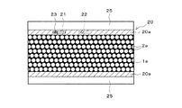
以下、本発明の実施形態について、添付の図面を参照して具体的に説明する。図1は本発明の実施形態に係るマイクロレンズアレイを示す。本実施形態のマイクロレンズアレイは、8枚の単位マイクロレンズアレイ2−1〜2−8により構成されている。各単位マイクロレンズアレイは、図3に示すように、複数個のマイクロレンズ2aが2次元的に配置されており、これらのマイクロレンズ2aの配置は図6に示す従来のマイクロレンズと同一である。また、各単位マイクロレンズアレイの構造も図4に示す従来のマイクロレンズアレイと同様であるが、図1の8枚構成の場合、各ガラス基板の上面にのみマイクロレンズが形成されている。そして、このマイクロレンズが形成されたレンズ領域において、マイクロレンズ2a間の隙間は、Cr膜からなる遮光膜1aが形成されている。
Hereinafter, embodiments of the present invention will be specifically described with reference to the accompanying drawings. FIG. 1 shows a microlens array according to an embodiment of the present invention. The microlens array of the present embodiment is composed of eight unit microlens arrays 2-1 to 2-8. In each unit microlens array, as shown in FIG. 3, a plurality of
このマイクロレンズ2aが形成されたレンズ領域の縁部には、アライメントマーク23が形成されたアライメント領域20が設けられており、このアライメント領域20には、Cr膜等の遮光膜20a等が形成されている。このアライメント領域20の更に縁側には、吸着領域25が設けられている。この吸着領域25は、搬送部材(図示せず)が真空吸着等により吸着して、単位マイクロレンズアレイを貼り合わせ装置に供給するための領域である。
An
図1に示すように、最上位の単位マイクロレンズアレイ2−1の上面におけるアライメント領域20には、Cr膜等の遮光膜20aが形成されている。また、最下位の単位マイクロレンズアレイ2−8の下面におけるアライメント領域20には、Cr膜等の遮光膜20bが形成されている。そして、最上位の単位マイクロレンズアレイ2−1の下面、最下位の単位マイクロレンズアレイ2−8の上面、及びその他の単位マイクロレンズアレイ2−2〜2−7の上下面には、同様にCr膜等の遮光膜20cが形成されている。遮光膜20cはいずれも単位マイクロレンズアレイの中央部の比較的広い領域が欠落して、開口部24が形成されている。この開口部24の大きさ及び位置は、全ての単位マイクロレンズアレイ2−1〜2−8について同一である。一方、最上位の単位マイクロレンズアレイ2−1の上面の遮光膜20aには、単位マイクロレンズアレイ2−1の左寄りの一部の領域が欠落して比較的小さな開口部21が形成されている。また、最下位の単位マイクロレンズアレイ2−8の下面の遮光膜20bには、単位マイクロレンズアレイ2−8の右寄りの一部の領域が欠落して比較的小さな開口部22が形成されている。そして、平面視で、開口部21の下方には、最下位の単位マイクロレンズアレイ2−8の下面の遮光膜20bが存在しており、開口部22の上方には、最上位の単位マイクロレンズアレイ2−1の上面の遮光膜20aが存在している。これにより、平面視で、遮光膜20a及び20bにより単位マイクロレンズアレイの全面が遮光されていることになる。
As shown in FIG. 1, a
単位マイクロレンズアレイ2−1の下面及び単位マイクロレンズアレイ2−2の上面に、アライメントマーク23−1の対が設けられており、単位マイクロレンズアレイ2−2の下面及び単位マイクロレンズアレイ2−3の上面に、アライメントマーク23−2の対が設けられており、単位マイクロレンズアレイ2−3の下面及び単位マイクロレンズアレイ2−4の上面に、アライメントマーク23−3の対が設けられており、単位マイクロレンズアレイ2−4の下面及び単位マイクロレンズアレイ2−5の上面に、アライメントマーク23−4の対が設けられており、単位マイクロレンズアレイ2−5の下面及び単位マイクロレンズアレイ2−6の上面に、アライメントマーク23−5の対が設けられており、単位マイクロレンズアレイ2−6の下面及び単位マイクロレンズアレイ2−7の上面に、アライメントマーク23−6の対が設けられており、単位マイクロレンズアレイ2−7の下面及び単位マイクロレンズアレイ2−8の上面に、アライメントマーク23−7の対が設けられている。これらのアライメントマーク23の対は、平面視で、重ならないような位置に配置されている。例えば、アライメントマーク23の対は、平面視で、順次相互に隣接するように配置されている。開口部24は、この開口部24内に、これらの7対のアライメントマーク23(23−1,23−2,23−3,23−4,23−5,23−6,23−7)がいずれも重ならないように配置するための大きさを有する。一方、最上位の単位マイクロレンズアレイ2−1の上面の遮光膜20aの開口部21は、アライメントマーク23−1,23−2,23−3,23−4が、平面視で全て開口部21内に入るような大きさを有している。また、最下位の単位マイクロレンズアレイ2−8の下面の遮光膜20bの開口部22は、アライメントマーク23−6,23−7が、平面視で全て開口部22内に入るような大きさを有している。
A pair of alignment marks 23-1 is provided on the lower surface of the unit microlens array 2-1 and the upper surface of the unit microlens array 2-2, and the lower surface of the unit microlens array 2-2 and the unit microlens array 2- 3 is provided with a pair of alignment marks 23-2, and a pair of alignment marks 23-3 is provided on the lower surface of the unit microlens array 2-3 and the upper surface of the unit microlens array 2-4. A pair of alignment marks 23-4 is provided on the lower surface of the unit microlens array 2-4 and the upper surface of the unit microlens array 2-5, and the lower surface of the unit microlens array 2-5 and the unit microlens array are provided. A pair of alignment marks 23-5 is provided on the upper surface of 2-6, and the
アライメントマーク23は、図2(a)に示す単位マイクロレンズアレイの下面に形成されたマーク23aと、図2(b)に示す単位マイクロレンズアレイの上面に形成されたマーク23b、23cとの対からなる。マーク23aはCr膜等の遮光膜が正方形に欠落した部分である。マーク23bもCr膜等の遮光膜が正方形に欠落した部分であるが、マーク23aよりも大きい。また、マーク23cは、マーク23bの中心に形成されたCr膜等の正方形の遮光膜である。そして、これらのアライメントマーク23の対において、両者が整合した場合には、図2(c)に示すように、マーク23aの中心にマーク23cが位置する。このアライメントマーク23の検出は、落射照明カメラを使用する。この落射照明カメラは、照明光を照射すると共に、この照明光の光軸と同軸的にマークで反射した反射光を入射させて、対象物の像を検出する。
The
次に、上述のごとく構成されたマイクロレンズアレイ及び貼り合わせ方法の動作について説明する。先ず、図1に示すように、アライメント領域20において、上面に小さな開口部21を有する最上位の単位マイクロレンズアレイ2−1と、下面に小さな開口部22を有する最下位の単位マイクロレンズアレイ2−8と、中間の大きさの開口部24を上面及び下面に有する単位マイクロレンズアレイ2−2〜2−7とを用意する。
Next, the operation of the microlens array and the bonding method configured as described above will be described. First, as shown in FIG. 1, in the
そして、搬送装置が単位マイクロレンズアレイ2−1、2−2を貼り合わせ装置に設置し、単位マイクロレンズアレイ2−1の上方から、落射照明カメラの照明光を単位マイクロレンズアレイ2−1に向けて照射し(図中、白抜き矢印にて示す)、単位マイクロレンズアレイ2−1,2−2間のアライメントマーク23−1を利用して、単位マイクロレンズアレイ2−1,2−2の位置合わせを行い、アライメントがとれた後、単位マイクロレンズアレイ2−1,2−2の縁部間に接着剤を注入し、紫外光の照射により接着剤を固化させて、両マイクロレンズアレイ2−1,2−2を相互に貼り合わせる。同様にして、単位マイクロレンズアレイ2−3、2−4をアライメントマーク23−3を利用して、落射照射カメラによりアライメントをとり、接着剤により単位マイクロレンズアレイ2−3、2−4を貼り合わせる。また、同様に、単位マイクロレンズアレイ2−5,2−6、及び単位マイクロレンズアレイ2−7,2−8を、夫々、アライメントマーク23−5及び23−7を利用して、相互にアライメントをとった後、貼り合わせる。 Then, the transfer device installs the unit microlens arrays 2-1 and 2-2 in the bonding device, and the illumination light of the epi-illumination camera is applied to the unit microlens array 2-1 from above the unit microlens array 2-1. The unit microlens arrays 2-1 and 2-2 are irradiated using the alignment marks 23-1 between the unit microlens arrays 2-1 and 2-2. After aligning and aligning, the adhesive is injected between the edges of the unit microlens arrays 2-1 and 2-2, and the adhesive is solidified by irradiation with ultraviolet light. 2-1 and 2-2 are pasted together. Similarly, the unit microlens arrays 2-3 and 2-4 are aligned by the epi-illumination camera using the alignment mark 23-3, and the unit microlens arrays 2-3 and 2-4 are pasted with an adhesive. Match. Similarly, the unit micro lens arrays 2-5 and 2-6 and the unit micro lens arrays 2-7 and 2-8 are aligned with each other using the alignment marks 23-5 and 23-7, respectively. After taking, stick together.
次に、既に貼り合わされている単位マイクロレンズアレイ2−1,2−2の対と、単位マイクロレンズアレイ2−3,2−4の対とを、搬送装置により、貼り合わせ装置に設置し、単位マイクロレンズアレイ2−2,2−3間のアライメントマーク23−2を利用して、落射照明カメラにより、マーク23a、23b、23cの像を検出して位置合わせをし、接着剤により、単位マイクロレンズアレイ2−2,2−3を貼り合わせる。これにより、単位マイクロレンズアレイ2−1,2−2,2−3,2−4の貼り合わせが終了する。また、既に貼り合わされている単位マイクロレンズアレイ2−5,2−6の対と、単位マイクロレンズアレイ2−7,2−8の対とを、搬送装置により、貼り合わせ装置に設置し、単位マイクロレンズアレイ2−6,2−7間のアライメントマーク23−6を利用して、落射照明カメラにより、マーク23a、23b、23cの像を検出して位置合わせをし、接着剤により、単位マイクロレンズアレイ2−6,2−7を貼り合わせる。
Next, the pair of unit microlens arrays 2-1 and 2-2 already bonded together and the pair of unit microlens arrays 2-3 and 2-4 are installed in the bonding apparatus by the transport device, Using the alignment mark 23-2 between the unit microlens arrays 2-2 and 2-3, the images of the
次いで、4枚の貼り合わせ済みの単位マイクロレンズアレイ2−1〜2−4と、4枚の貼り合わせ済みの単位マイクロレンズアレイ2−5〜2−8とを、搬送装置により貼り合わせ装置に設置し、単位マイクロレンズアレイ2−4と単位マイクロレンズアレイ2−5との間のアライメントマーク23−4を利用して、4枚の単位マイクロレンズアレイ同士を位置合わせし、接着剤により単位マイクロレンズアレイ2−4と単位マイクロレンズアレイ2−5とを接合して貼り合わせる。このようにして、8枚の単位マイクロレンズアレイ2−1〜2−8の全てが、相互に貼り合わされる。貼り合わせ時においては、アライメントマーク23を使用して、単位マイクロレンズアレイの相互間を位置合わせして、単位マイクロレンズアレイ同士を接合するので、マイクロレンズの光軸は全て高精度で一致したものとなる。 Next, the four unit microlens arrays 2-1 to 2-4 that have been bonded together and the four unit microlens arrays 2-5 to 2-8 that have been bonded together are combined into a bonding apparatus by a transport device. The four unit microlens arrays are aligned using an alignment mark 23-4 between the unit microlens array 2-4 and the unit microlens array 2-5, and the unit microlens is aligned with an adhesive. The lens array 2-4 and the unit micro lens array 2-5 are bonded and bonded together. In this way, all the eight unit microlens arrays 2-1 to 2-8 are bonded to each other. At the time of bonding, the alignment marks 23 are used to align the unit microlens arrays, and the unit microlens arrays are joined together, so that the optical axes of the microlenses all coincide with each other with high accuracy. It becomes.
この場合に、単位マイクロレンズアレイ2−1,2−2間、単位マイクロレンズアレイ2−3,2−4間、単位マイクロレンズアレイ2−7,2−8間のアライメントマーク23−1,23−3,23−7の像の検出に際し、落射照射カメラからの照明光は、アライメントマーク23の下方の近傍には、遮光膜20b、20cが存在しないので、アライメントマーク23からの反射光のみが落射照明カメラに入射する。従って、落射カメラは、アライメントマーク23からの反射光を高コントラストで検出する。従って、アライメントマーク23の像(マーク23cの像)を明瞭に検出することができ、アライメント精度が高い。また、単位マイクロレンズアレイ2−2,2−3間、単位マイクロレンズアレイ2−6,2−7間のアライメントマーク23−2,23−6の像の検出に際しても、同様に、アライメントマーク23の下方の近傍に遮光膜20b、20cが存在しないので、アライメントマーク23−2,23−6を高コントランストで検出することができる。一方、単位マイクロレンズアレイ2−5と単位マイクロレンズアレイ2−6との間のアライメントマーク23−5の検出に際し、アライメントマーク23−5の下方に遮光膜20bが存在するが、このアライメントマーク23−5と最下位の単位マイクロレンズアレイ2−8の下面の遮光膜20bとの間の距離は大きいので、遮光膜20bからの反射光が落射照明カメラに入射する光量は極めて少ない。同様に、単位マイクロレンズアレイ2−4と単位マイクロレンズアレイ2−5との間のアライメントマーク23−4の検出においても、その下方には、最下位の単位マイクロレンズアレイ2−8の下面の遮光膜20bが存在するが、同様に、このアライメントマーク23−4と遮光膜20bとの間の距離が大きいので、遮光膜20bからの反射光が落射照明カメラに入射する光量は極めて少ない。よって、これらのアライメントマーク23−4からの反射光も、高コントラストで検出することができる。
In this case, alignment marks 23-1, 23 between the unit microlens arrays 2-1, 2-2, between the unit microlens arrays 2-3, 2-4, and between the unit microlens arrays 2-7, 2-8. In the detection of the images of −3 and 23-7, the illumination light from the epi-illumination camera does not have the
得られたマイクロレンズアレイは、最上位のマイクロレンズアレイ2−1の上面の遮光膜20aと最下位のマイクロレンズアレイ2−8の下面の遮光膜20bとにより、平面視でアライメント領域20の全領域が遮光されているので、露光時にこの露光領域20を介して、露光光が基板を露光してしまうことがない。即ち、遮光膜20aの開口部21の下方には、遮光膜20bが存在し、遮光膜20bの開口部22の上方には遮光膜20aが存在するので、露光光がこれらのアライメント領域20を透過してしまうことはない。
The obtained microlens array has the entire light-shielding
なお、開口部21の右端の位置は、平面視で、開口部22の左端の位置より左方に位置していて、この間で、遮光膜20aと遮光膜20bとが平面視で重なっている。これは、露光光が、通常、±2〜3°の広がりを持つので、この露光光の広がり分を遮光するための遮光膜重なり領域である。
The position of the right end of the
このようにして、単位マイクロレンズアレイを2枚ずつアライメントをとり、次に、2対ずつアライメントをとり、次に、4対ずつアライメントをとるというように、単位マイクロレンズアレイの枚数に応じて、順次、アライメントをとっていき、最後のアライメントをとると、マイクロレンズアレイが完成する。この最後にアライメントをとるアライメントマークの下方には、最下位単位マイクロレンズアレイの下面の遮光膜が存在しても、この最後のアライメントマークと最下位遮光膜との間の距離は大きいので、最下位遮光膜からの反射光のコントラストへの影響は極めて少ない。一方、この最後のアライメントをとるアライメントマークの下方に遮光膜を設けることにより、平面視で、アライメント領域の全面を遮光することができ、露光光がアライメント領域を透過して基板を露光してしまうことを防止することができる。 In this way, according to the number of unit microlens arrays, such as aligning two unit microlens arrays, then aligning two pairs, then aligning four pairs, The alignment is sequentially performed, and the final alignment is completed to complete the microlens array. Even if there is a light-shielding film on the lower surface of the lowest-order unit microlens array below the alignment mark to be aligned last, the distance between this last alignment mark and the lowest-order light-shielding film is large. The influence on the contrast of the reflected light from the lower light shielding film is extremely small. On the other hand, by providing a light-shielding film below the alignment mark for the final alignment, the entire alignment region can be shielded in plan view, and exposure light passes through the alignment region to expose the substrate. This can be prevented.
なお、本発明は上記実施形態に限定されないことは勿論である。例えば、単位マイクロレンズアレイが4枚の場合は、その相互間に3個のアライメントマークの対が設けられるが、上方のアライメントマーク23−1と中央のアライメントマーク23−2との下方に、最下位の単位マイクロレンズアレイ2−4の下面の遮光膜を位置させ、この最下位の単位マイクロレンズアレイ2−4の下面の遮光膜は、下方のアライメントマーク23−3の下方の位置を開口部とし、最上位の単位マイクロレンズアレイ2−1の上面の遮光膜は、上方のアライメントマーク23−1と中央のアライメントマーク23−2の上方の位置を開口部とすればよい。その他の遮光膜は3個のアライメントマークの全てを遮光しないように開口部を設けておく。 Needless to say, the present invention is not limited to the above embodiment. For example, when there are four unit microlens arrays, three pairs of alignment marks are provided between them, but below the upper alignment mark 23-1 and the center alignment mark 23-2, The light shielding film on the lower surface of the lower unit microlens array 2-4 is positioned, and the light shielding film on the lower surface of the lowest unit microlens array 2-4 has an opening at a position below the lower alignment mark 23-3. As for the light shielding film on the upper surface of the uppermost unit microlens array 2-1, the upper position of the upper alignment mark 23-1 and the upper alignment mark 23-2 may be an opening. The other light-shielding films are provided with openings so as not to shield all three alignment marks.
また、図1に示す実施形態は、全てのアライメントマーク23−1等が平面視で相互に異なる位置に設けられているが、本実施形態では、第1工程で、2枚の単位マイクロレンズアレイ同士を貼り合わせ、第2工程で、2枚で1対の単位マイクロレンズアレイ同士を貼り合わせ、第3工程で、4枚で1群の単位マイクロレンズアレイ同士を貼り合わせているので、上記実施形態に限らず、この第1工程と、第2工程と、第3工程とでアライメントマーク対の位置を相互に異なるものにすれば良い。即ち、図1のアライメントマーク23−1,23−3,23−5,23−7の各対は、平面視で同一位置に設けても良い。また、アライメントマーク23−2,23−6の対も、平面視で同一位置に設けても良い。結局、アライメントマーク23−1,23−3,23−5,23−7と、アライメントマーク23−2,23−6と、アライメントマーク23−4とが平面視で異なる位置に設けられていれば、上方から落射照明カメラにより、各対のアライメントマークを観察することができる。 In the embodiment shown in FIG. 1, all the alignment marks 23-1 and the like are provided at different positions in plan view. In this embodiment, two unit microlens arrays are used in the first step. In the second step, a pair of unit microlens arrays are bonded together in the second step, and in the third step, one group of unit microlens arrays are bonded together in the third step. The position of the alignment mark pair may be different from each other in the first step, the second step, and the third step. That is, each pair of the alignment marks 23-1, 23-3, 23-5, and 23-7 in FIG. 1 may be provided at the same position in plan view. The pair of alignment marks 23-2 and 23-6 may also be provided at the same position in plan view. After all, if alignment marks 23-1, 23-3, 23-5, 23-7, alignment marks 23-2, 23-6, and alignment mark 23-4 are provided at different positions in plan view. Each pair of alignment marks can be observed by an epi-illumination camera from above.
更に、図1において、最下位の単位マイクロレンズアレイ2−8とその上の単位マイクロレンズアレイ2−7とをアライメントをとって貼り合わせ、次に、単位マイクロレンズアレイ2−7とその上の単位マイクロレンズアレイ2−6とをアライメントをとって貼り合わせ、次に、単位マイクロレンズアレイ2−6とその上の単位マイクロレンズアレイ2−5とをアライメントをとって貼り合わせるというように、下から順に、2個の単位マイクロレンズアレイ同士をアライメントをとって貼り合わせるという工程で、各単位マイクロレンズアレイを張り合わせることもできる。この場合に、落射照明カメラにより、アライメントマーク対を照明するために、アライメントをとろうとする2個の単位マイクロレンズアレイの上位置の単位マイクロレンズアレイの上面の開口部に、平面視で整合するように、アライメントマーク対が配置されていることが必要である。また、露光時に、露光光がアライメント領域を透過して、下方の基板を露光してしまわないようにするために、最終的に張り合わされた単位マイクロレンズアレイの全ての開口部が平面視で重なるような領域が存在しないように、遮光膜が配置されていることが必要である。 Further, in FIG. 1, the lowest unit microlens array 2-8 and the unit microlens array 2-7 thereabove are aligned and bonded together, and then the unit microlens array 2-7 and the upper unit microlens array 2-7 are bonded together. The unit microlens array 2-6 is aligned and bonded, and then the unit microlens array 2-6 and the unit microlens array 2-5 are aligned and bonded together. Each unit microlens array can also be bonded together in the process of aligning and bonding the two unit microlens arrays in order. In this case, in order to illuminate the alignment mark pair by the epi-illumination camera, alignment is made in plan view with the opening on the upper surface of the unit microlens array at the upper position of the two unit microlens arrays to be aligned. Thus, it is necessary that the alignment mark pair is arranged. Further, in order to prevent exposure light from passing through the alignment region and exposing the lower substrate during exposure, all the openings of the unit microlens arrays that are finally bonded overlap in plan view. It is necessary that the light shielding film is disposed so that such a region does not exist.
本発明によれば、積層された単位マイクロレンズアレイ同士を高精度で整合させることができると共に、露光光の透光を防止することができ、高性能のマイクロレンズアレイの製造に寄与する。 According to the present invention, the stacked unit microlens arrays can be aligned with high accuracy, and the transmission of exposure light can be prevented, contributing to the manufacture of a high-performance microlens array.
1:基板
2:マイクロレンズアレイ
2a:マイクロレンズ
2−1,2−2,2−3,2−4,2−5,2−6,2−7,2−8:単位マイクロレンズアレイ
3:マスク
10:開口
10a:遮光膜
11:円形絞り
12:6角視野絞り
20:アライメント領域
20a、20b、20c:遮光膜
21,22,24:開口部
23,23−1,23−2,23−4,23−5,23−6,23−7:アライメントマーク
1: Substrate 2:
Claims (3)
各単位マイクロレンズアレイは、前記マイクロレンズが配置されたレンズ領域と、このレンズ領域の縁部のアライメントマークが形成されたアライメント領域と、を有し、
前記アライメント領域における前記各単位マイクロレンズアレイの上面及び下面には、遮光膜と、前記遮光膜が欠落した開口部と、が設けられており、
前記アライメントマークは、前記単位マイクロレンズアレイ間の対向面における前記開口部内に形成され、前記各アライメントマーク対は、平面視で相互に異なる位置に配置されており、
上位置の単位マイクロレンズアレイの下面に設けられたアライメントマークと下位置の単位マイクロレンズアレイの上面に設けられたアライメントマークとで、前記上位置のマイクロレンズアレイと下位置のマイクロレンズアレイとの整合をとるアライメントマーク対を構成し、
平面視で、最上位の単位マイクロレンズアレイの上面の遮光膜が欠落した開口部の下方に、最下位の単位マイクロレンズアレイの下面の遮光膜が存在して、両者により平面視で全面が遮光されていることを特徴とするマイクロレンズアレイ。 In a microlens array configured by laminating a plurality of unit microlens arrays configured by two-dimensionally arranging a plurality of microlenses in the thickness direction,
Each unit microlens array has a lens region in which the microlens is arranged, and an alignment region in which an alignment mark at the edge of the lens region is formed,
On the upper and lower surfaces of each unit microlens array in the alignment region, a light shielding film and an opening lacking the light shielding film are provided,
The alignment mark is formed in the opening on the facing surface between the unit microlens arrays, and the alignment mark pairs are arranged at different positions in plan view ,
An alignment mark provided on the lower surface of the unit microlens array at the upper position and an alignment mark provided on the upper surface of the unit microlens array at the lower position, and the microlens array at the upper position and the microlens array at the lower position. Configure alignment mark pairs for alignment,
In plan view, there is a light shielding film on the lower surface of the lowest unit microlens array below the opening where the light shielding film on the upper surface of the uppermost unit microlens array is missing. A microlens array characterized by being made.
各単位マイクロレンズアレイは、前記マイクロレンズが配置されたレンズ領域と、このレンズ領域の縁部のアライメントマークが形成されたアライメント領域と、を有し、
前記アライメント領域における前記各単位マイクロレンズアレイの上面及び下面には、遮光膜と、前記遮光膜が欠落した開口部と、が設けられており、
前記アライメントマークは、前記単位マイクロレンズアレイ間の対向面における前記開口部内に形成されており、
上位置の単位マイクロレンズアレイの下面に設けられたアライメントマークと下位置の単位マイクロレンズアレイの上面に設けられたアライメントマークとで、前記上位置のマイクロレンズアレイと下位置のマイクロレンズアレイとの整合をとるアライメントマーク対を構成し、
平面視で、最上位の単位マイクロレンズアレイの上面の遮光膜が欠落した開口部の下方に、最下位の単位マイクロレンズアレイの下面の遮光膜が存在して、両者により平面視で全面が遮光されているものであり、
先ず、2枚の単位マイクロレンズアレイ毎に上位置の単位マイクロレンズアレイの下面に設けられたアライメントマークと、下位置の単位マイクロレンズアレイの上面に設けられたアライメントマークとのアライメントマーク対を、落射照明カメラにより照明光を照射してその反射光を検出することにより、これらの単位マイクロレンズアレイ同士のアライメントをとり、相互に貼り合わせる第1工程と、
次に、2枚で1対の単位マイクロレンズアレイを2対毎に上位置の1対の単位マイクロレンズアレイの下方の単位マイクロレンズアレイの下面に設けられたアライメントマークと下位置の1対の単位マイクロレンズアレイの上方の単位マイクロレンズアレイの上面に設けられたアライメントマークとのアライメントマーク対を、落射照明カメラにより照明光を照射してその反射光を検出することにより、これらの1対の単位マイクロレンズアレイ同士のアライメントをとり、相互に貼り合わせる第2工程と、
以後、必要に応じて、同様にして、偶数枚で1群の単位マイクロレンズアレイを2群毎に上位置の1群の単位マイクロレンズアレイの下方の単位マイクロレンズアレイの下面に設けられたアライメントマークと下位置の1群の単位マイクロレンズアレイの上方の単位マイクロレンズアレイの上面に設けられたアライメントマークとのアライメントマーク対を、落射照明カメラにより照明光を照射してその反射光を検出することにより、これらの1群の単位マイクロレンズアレイ同士のアライメントをとり、相互に貼り合わせる第3工程と、
を有し、
第1工程で使用される前記アライメントマーク対と、第2工程で使用される前記アライメントマーク対と、第3工程で使用される前記アライメントマーク対とは、平面視で相互に異なる位置に配置されており、
最後にアライメントをとるアライメントマーク対は、平面視で、前記最上位の単位マイクロレンズアレイの上面の遮光膜が欠落した開口部と、最下位の単位マイクロレンズアレイの下面の遮光膜とが重なる領域に配置されていることを特徴とするマイクロレンズアレイの貼り合わせ方法。 In a manufacturing method of a microlens array configured by laminating a plurality of unit microlens arrays configured by two-dimensionally arranging a plurality of microlenses in the thickness direction,
Each unit microlens array has a lens region in which the microlens is arranged, and an alignment region in which an alignment mark at the edge of the lens region is formed,
On the upper and lower surfaces of each unit microlens array in the alignment region, a light shielding film and an opening lacking the light shielding film are provided,
The alignment mark is formed in the opening in the facing surface between the unit microlens arrays,
An alignment mark provided on the lower surface of the unit microlens array at the upper position and an alignment mark provided on the upper surface of the unit microlens array at the lower position, and the microlens array at the upper position and the microlens array at the lower position. Configure alignment mark pairs for alignment,
In plan view, there is a light shielding film on the lower surface of the lowest unit microlens array below the opening where the light shielding film on the upper surface of the uppermost unit microlens array is missing. Is what has been
First, an alignment mark pair of an alignment mark provided on the lower surface of the upper unit microlens array and an alignment mark provided on the upper surface of the lower unit microlens array for every two unit microlens arrays, A first step of aligning these unit microlens arrays by irradiating illumination light with an epi-illumination camera and detecting the reflected light, and bonding them together,
Next, two pairs of unit microlens arrays are arranged in pairs, and an alignment mark provided on the lower surface of the unit microlens array below the pair of unit microlens arrays at the upper position and a pair of lower positions. The pair of alignment marks with the alignment mark provided on the upper surface of the unit microlens array above the unit microlens array is irradiated with illumination light by an epi-illumination camera, and the reflected light is detected. A second step of aligning the unit microlens arrays and bonding them together;
Thereafter, in the same manner, if necessary, one group of unit microlens arrays is provided on the lower surface of the unit microlens array below the group of unit microlens arrays at the upper position for every two groups. The reflected light is detected by irradiating the alignment mark pair of the mark and the alignment mark provided on the upper surface of the unit microlens array above the group of unit microlens arrays in the lower position with an incident illumination camera. A third step of aligning these one group of unit microlens arrays and bonding them together;
Have
The alignment mark pair used in the first step, the alignment mark pair used in the second step, and the alignment mark pair used in the third step are arranged at different positions in plan view. And
The alignment mark pair to be aligned last is an area where, in plan view, the opening where the light shielding film on the upper surface of the uppermost unit microlens array is missing and the light shielding film on the lower surface of the lowermost unit microlens array overlap. A method for laminating a microlens array, wherein the microlens array is disposed on the substrate.
各単位マイクロレンズアレイは、前記マイクロレンズが配置されたレンズ領域と、このレンズ領域の縁部のアライメントマークが形成されたアライメント領域と、を有し、
前記アライメント領域における前記各単位マイクロレンズアレイの上面及び下面には、遮光膜と、前記遮光膜が欠落した開口部と、が設けられており、
前記アライメントマークは、前記単位マイクロレンズアレイ間の対向面における前記開口部内に形成されており、
上位置の単位マイクロレンズアレイの下面に設けられたアライメントマークと下位置の単位マイクロレンズアレイの上面に設けられたアライメントマークとで、前記上位置のマイクロレンズアレイと下位置のマイクロレンズアレイとの整合をとるアライメントマーク対を構成し、各アライメントマーク対は、平面視で相互に異なる位置に配置されており、
先ず、最下位の単位マイクロレンズアレイとその上位の単位マイクロレンズアレイとに対し、落射照明カメラにより照明光を照射して、これらの単位マイクロレンズアレイの対向面に形成されたアライメントマーク対からの反射光を検出して、これらの単位マイクロレンズアレイ同士のアライメントをとり、両単位マイクロレンズアレイを相互に張り合わせる第1工程と、
同様にして、下から順に2個ずつ単位マイクロレンズアレイ間のアライメントを、両者間のアライメントマーク対を利用してとり、両単位マイクロレンズアレイを相互に貼り合わせる第2工程と、
同様にして、上下に隣接する2個の単位マイクロレンズアレイ同士を、その間のアライメントマーク対を利用してアライメントをとると共に、相互に貼り合わせ、最終的に最上位の単位マイクロレンズアレイまで貼り合わせる第3工程と、
を有し、
下から順に複数個のアライメントマーク対は、平面視で、最下位の単位マイクロレンズアレイの下面に形成された開口部に整合する位置に配置され、
各アライメントマーク対は、平面視で、そのアライメントマーク対が形成された上位置の単位マイクロレンズアレイの上面に形成された開口部に整合する位置に配置され、
平面視で、全ての開口部が重なる領域が存在しないように、遮光膜が配置されていることを特徴とするマイクロレンズアレイの貼り合わせ方法。 In a manufacturing method of a microlens array configured by laminating a plurality of unit microlens arrays configured by two-dimensionally arranging a plurality of microlenses in the thickness direction,
Each unit microlens array has a lens region in which the microlens is arranged, and an alignment region in which an alignment mark at the edge of the lens region is formed,
On the upper and lower surfaces of each unit microlens array in the alignment region, a light shielding film and an opening lacking the light shielding film are provided,
The alignment mark is formed in the opening in the facing surface between the unit microlens arrays,
An alignment mark provided on the lower surface of the unit microlens array at the upper position and an alignment mark provided on the upper surface of the unit microlens array at the lower position, and the microlens array at the upper position and the microlens array at the lower position. Alignment mark pairs for alignment are configured, and each alignment mark pair is arranged at a different position in plan view.
First, the illumination light is irradiated to the lowest unit microlens array and the upper unit microlens array by an epi-illumination camera, and from the alignment mark pairs formed on the opposing surfaces of these unit microlens arrays. A first step of detecting reflected light, aligning the unit microlens arrays, and bonding the unit microlens arrays together;
Similarly, a second step of aligning two unit microlens arrays in order from the bottom using an alignment mark pair between the two and bonding the unit microlens arrays to each other,
Similarly, two unit microlens arrays adjacent to each other in the upper and lower sides are aligned using an alignment mark pair between them, and bonded to each other, and finally bonded to the uppermost unit microlens array. A third step;
Have
A plurality of alignment mark pairs in order from the bottom are arranged in a position aligned with the opening formed on the lower surface of the lowest unit microlens array in plan view,
Each pair of alignment marks is arranged at a position that aligns with the opening formed on the upper surface of the unit microlens array in the upper position where the alignment mark pair is formed in plan view,
A method of attaching a microlens array, wherein a light shielding film is disposed so that there is no region where all the openings overlap in a plan view.
Priority Applications (1)
| Application Number | Priority Date | Filing Date | Title |
|---|---|---|---|
| JP2011268430A JP5874966B2 (en) | 2011-12-07 | 2011-12-07 | Microlens array and bonding method thereof |
Applications Claiming Priority (1)
| Application Number | Priority Date | Filing Date | Title |
|---|---|---|---|
| JP2011268430A JP5874966B2 (en) | 2011-12-07 | 2011-12-07 | Microlens array and bonding method thereof |
Publications (2)
| Publication Number | Publication Date |
|---|---|
| JP2013120297A JP2013120297A (en) | 2013-06-17 |
| JP5874966B2 true JP5874966B2 (en) | 2016-03-02 |
Family
ID=48772950
Family Applications (1)
| Application Number | Title | Priority Date | Filing Date |
|---|---|---|---|
| JP2011268430A Active JP5874966B2 (en) | 2011-12-07 | 2011-12-07 | Microlens array and bonding method thereof |
Country Status (1)
| Country | Link |
|---|---|
| JP (1) | JP5874966B2 (en) |
Families Citing this family (1)
| Publication number | Priority date | Publication date | Assignee | Title |
|---|---|---|---|---|
| JP6304254B2 (en) * | 2013-08-09 | 2018-04-04 | 旭硝子株式会社 | Optical member, method for manufacturing the same, and imaging apparatus |
Family Cites Families (5)
| Publication number | Priority date | Publication date | Assignee | Title |
|---|---|---|---|---|
| US5363240A (en) * | 1992-11-13 | 1994-11-08 | Ricoh Company, Ltd. | Image forming device and method for producing it |
| JPH1062604A (en) * | 1996-08-19 | 1998-03-06 | Sony Corp | Manufacture of optical board and liquid crystal display |
| JP2002196104A (en) * | 2000-12-27 | 2002-07-10 | Seiko Epson Corp | Microlens array, method for manufacturing the same and optical device |
| WO2009133756A1 (en) * | 2008-04-28 | 2009-11-05 | コニカミノルタオプト株式会社 | Method for producing wafer lens assembly and method for producing wafer lens |
| WO2011132690A1 (en) * | 2010-04-21 | 2011-10-27 | コニカミノルタオプト株式会社 | Wafer lens, laminated wafer lens, wafer lens cutting method and laminated wafer lens cutting method |
-
2011
- 2011-12-07 JP JP2011268430A patent/JP5874966B2/en active Active
Also Published As
| Publication number | Publication date |
|---|---|
| JP2013120297A (en) | 2013-06-17 |
Similar Documents
| Publication | Publication Date | Title |
|---|---|---|
| TWI598702B (en) | Alignment device for exposure device and alignment mark | |
| JP5294488B2 (en) | Exposure equipment | |
| TWI544284B (en) | Microlens array and scanning exposure apparatus using the same | |
| WO2012056817A1 (en) | Scanning exposure apparatus using microlens array | |
| JP5756813B2 (en) | Substrate exposure method | |
| JP2007102094A (en) | Aligner | |
| JP5354803B2 (en) | Exposure equipment | |
| TWI546630B (en) | Scanning exposure apparatus using microlens array | |
| JP6004157B2 (en) | Manufacturing apparatus and manufacturing method of three-dimensional liquid crystal display device | |
| JP5760250B2 (en) | Microlens array and scan exposure apparatus using the same | |
| JP5874966B2 (en) | Microlens array and bonding method thereof | |
| JP2007102093A (en) | Photomask and exposure method using same | |
| KR101674133B1 (en) | Photomask | |
| JP5895275B2 (en) | Alignment mark and exposure apparatus | |
| JP5953037B2 (en) | Micro lens array bonding device | |
| JP5874900B2 (en) | Alignment device for exposure equipment | |
| JP5953038B2 (en) | Apparatus and method for measuring focal length of microlens array | |
| JP2012128193A (en) | Microlens array and scan exposure device using the same |
Legal Events
| Date | Code | Title | Description |
|---|---|---|---|
| A621 | Written request for application examination |
Free format text: JAPANESE INTERMEDIATE CODE: A621 Effective date: 20141125 |
|
| A977 | Report on retrieval |
Free format text: JAPANESE INTERMEDIATE CODE: A971007 Effective date: 20150928 |
|
| A131 | Notification of reasons for refusal |
Free format text: JAPANESE INTERMEDIATE CODE: A131 Effective date: 20151013 |
|
| A521 | Written amendment |
Free format text: JAPANESE INTERMEDIATE CODE: A523 Effective date: 20151130 |
|
| TRDD | Decision of grant or rejection written | ||
| A01 | Written decision to grant a patent or to grant a registration (utility model) |
Free format text: JAPANESE INTERMEDIATE CODE: A01 Effective date: 20151222 |
|
| A61 | First payment of annual fees (during grant procedure) |
Free format text: JAPANESE INTERMEDIATE CODE: A61 Effective date: 20160107 |
|
| R150 | Certificate of patent or registration of utility model |
Ref document number: 5874966 Country of ref document: JP Free format text: JAPANESE INTERMEDIATE CODE: R150 |
|
| R250 | Receipt of annual fees |
Free format text: JAPANESE INTERMEDIATE CODE: R250 |