JP5872075B2 - High flow rate water treatment separation membrane, water treatment module and water treatment device with excellent chlorine resistance - Google Patents
High flow rate water treatment separation membrane, water treatment module and water treatment device with excellent chlorine resistance Download PDFInfo
- Publication number
- JP5872075B2 JP5872075B2 JP2014557583A JP2014557583A JP5872075B2 JP 5872075 B2 JP5872075 B2 JP 5872075B2 JP 2014557583 A JP2014557583 A JP 2014557583A JP 2014557583 A JP2014557583 A JP 2014557583A JP 5872075 B2 JP5872075 B2 JP 5872075B2
- Authority
- JP
- Japan
- Prior art keywords
- water treatment
- separation membrane
- droplet
- treatment separation
- active layer
- Prior art date
- Legal status (The legal status is an assumption and is not a legal conclusion. Google has not performed a legal analysis and makes no representation as to the accuracy of the status listed.)
- Active
Links
- 239000012528 membrane Substances 0.000 title claims description 108
- XLYOFNOQVPJJNP-UHFFFAOYSA-N water Substances O XLYOFNOQVPJJNP-UHFFFAOYSA-N 0.000 title claims description 96
- 238000000926 separation method Methods 0.000 title claims description 94
- ZAMOUSCENKQFHK-UHFFFAOYSA-N Chlorine atom Chemical compound [Cl] ZAMOUSCENKQFHK-UHFFFAOYSA-N 0.000 title description 12
- 239000000460 chlorine Substances 0.000 title description 12
- 229910052801 chlorine Inorganic materials 0.000 title description 12
- 239000004952 Polyamide Substances 0.000 claims description 76
- 229920002647 polyamide Polymers 0.000 claims description 76
- 239000007864 aqueous solution Substances 0.000 claims description 57
- 238000006116 polymerization reaction Methods 0.000 claims description 10
- PYWVYCXTNDRMGF-UHFFFAOYSA-N rhodamine B Chemical compound [Cl-].C=12C=CC(=[N+](CC)CC)C=C2OC2=CC(N(CC)CC)=CC=C2C=1C1=CC=CC=C1C(O)=O PYWVYCXTNDRMGF-UHFFFAOYSA-N 0.000 claims description 8
- 229940043267 rhodamine b Drugs 0.000 claims description 8
- 239000010410 layer Substances 0.000 description 130
- 239000000243 solution Substances 0.000 description 125
- 150000001412 amines Chemical class 0.000 description 63
- -1 acyl halide compound Chemical class 0.000 description 47
- 238000000034 method Methods 0.000 description 39
- 238000012695 Interfacial polymerization Methods 0.000 description 33
- 150000003839 salts Chemical class 0.000 description 25
- 230000003746 surface roughness Effects 0.000 description 17
- ZMXDDKWLCZADIW-UHFFFAOYSA-N N,N-Dimethylformamide Chemical compound CN(C)C=O ZMXDDKWLCZADIW-UHFFFAOYSA-N 0.000 description 15
- 125000003368 amide group Chemical group 0.000 description 14
- 125000003178 carboxy group Chemical group [H]OC(*)=O 0.000 description 14
- 238000004519 manufacturing process Methods 0.000 description 14
- 238000002474 experimental method Methods 0.000 description 13
- ZMANZCXQSJIPKH-UHFFFAOYSA-N Triethylamine Chemical compound CCN(CC)CC ZMANZCXQSJIPKH-UHFFFAOYSA-N 0.000 description 12
- 238000006243 chemical reaction Methods 0.000 description 12
- 229920002492 poly(sulfone) Polymers 0.000 description 12
- 238000001223 reverse osmosis Methods 0.000 description 11
- WZCQRUWWHSTZEM-UHFFFAOYSA-N 1,3-phenylenediamine Chemical compound NC1=CC=CC(N)=C1 WZCQRUWWHSTZEM-UHFFFAOYSA-N 0.000 description 9
- 230000008859 change Effects 0.000 description 9
- 238000000576 coating method Methods 0.000 description 9
- 239000012466 permeate Substances 0.000 description 9
- 239000011248 coating agent Substances 0.000 description 8
- 230000000052 comparative effect Effects 0.000 description 8
- 150000001266 acyl halides Chemical class 0.000 description 7
- UWCPYKQBIPYOLX-UHFFFAOYSA-N benzene-1,3,5-tricarbonyl chloride Chemical compound ClC(=O)C1=CC(C(Cl)=O)=CC(C(Cl)=O)=C1 UWCPYKQBIPYOLX-UHFFFAOYSA-N 0.000 description 7
- 238000005033 Fourier transform infrared spectroscopy Methods 0.000 description 6
- 238000004566 IR spectroscopy Methods 0.000 description 6
- FAPWRFPIFSIZLT-UHFFFAOYSA-M Sodium chloride Chemical compound [Na+].[Cl-] FAPWRFPIFSIZLT-UHFFFAOYSA-M 0.000 description 6
- 230000007423 decrease Effects 0.000 description 6
- 229940018564 m-phenylenediamine Drugs 0.000 description 6
- 239000002253 acid Substances 0.000 description 5
- 230000015572 biosynthetic process Effects 0.000 description 5
- 238000004043 dyeing Methods 0.000 description 5
- 238000005259 measurement Methods 0.000 description 5
- 239000004745 nonwoven fabric Substances 0.000 description 5
- 239000002904 solvent Substances 0.000 description 5
- MIOPJNTWMNEORI-GMSGAONNSA-N (S)-camphorsulfonic acid Chemical compound C1C[C@@]2(CS(O)(=O)=O)C(=O)C[C@@H]1C2(C)C MIOPJNTWMNEORI-GMSGAONNSA-N 0.000 description 4
- 238000001035 drying Methods 0.000 description 4
- 238000011156 evaluation Methods 0.000 description 4
- 239000000463 material Substances 0.000 description 4
- 239000003960 organic solvent Substances 0.000 description 4
- 230000008569 process Effects 0.000 description 4
- 238000000746 purification Methods 0.000 description 4
- 229910019093 NaOCl Inorganic materials 0.000 description 3
- 239000003929 acidic solution Substances 0.000 description 3
- 238000004458 analytical method Methods 0.000 description 3
- 125000004432 carbon atom Chemical group C* 0.000 description 3
- 239000011247 coating layer Substances 0.000 description 3
- 238000007796 conventional method Methods 0.000 description 3
- 238000010586 diagram Methods 0.000 description 3
- 230000000694 effects Effects 0.000 description 3
- 230000001788 irregular Effects 0.000 description 3
- 239000007791 liquid phase Substances 0.000 description 3
- 239000011368 organic material Substances 0.000 description 3
- 230000002093 peripheral effect Effects 0.000 description 3
- 230000000704 physical effect Effects 0.000 description 3
- 239000002798 polar solvent Substances 0.000 description 3
- 229920000728 polyester Polymers 0.000 description 3
- 239000011780 sodium chloride Substances 0.000 description 3
- SUKJFIGYRHOWBL-UHFFFAOYSA-N sodium hypochlorite Chemical compound [Na+].Cl[O-] SUKJFIGYRHOWBL-UHFFFAOYSA-N 0.000 description 3
- 239000007787 solid Substances 0.000 description 3
- VEXZGXHMUGYJMC-UHFFFAOYSA-N Hydrochloric acid Chemical compound Cl VEXZGXHMUGYJMC-UHFFFAOYSA-N 0.000 description 2
- GLUUGHFHXGJENI-UHFFFAOYSA-N Piperazine Chemical compound C1CNCCN1 GLUUGHFHXGJENI-UHFFFAOYSA-N 0.000 description 2
- 238000010306 acid treatment Methods 0.000 description 2
- 125000003118 aryl group Chemical group 0.000 description 2
- 230000008901 benefit Effects 0.000 description 2
- HFACYLZERDEVSX-UHFFFAOYSA-N benzidine Chemical compound C1=CC(N)=CC=C1C1=CC=C(N)C=C1 HFACYLZERDEVSX-UHFFFAOYSA-N 0.000 description 2
- 230000005540 biological transmission Effects 0.000 description 2
- 239000002131 composite material Substances 0.000 description 2
- 238000007598 dipping method Methods 0.000 description 2
- 239000008235 industrial water Substances 0.000 description 2
- 239000000203 mixture Substances 0.000 description 2
- 230000003204 osmotic effect Effects 0.000 description 2
- 239000002861 polymer material Substances 0.000 description 2
- 238000005507 spraying Methods 0.000 description 2
- 239000000126 substance Substances 0.000 description 2
- XBTRYWRVOBZSGM-UHFFFAOYSA-N (4-methylphenyl)methanediamine Chemical compound CC1=CC=C(C(N)N)C=C1 XBTRYWRVOBZSGM-UHFFFAOYSA-N 0.000 description 1
- CBCKQZAAMUWICA-UHFFFAOYSA-N 1,4-phenylenediamine Chemical compound NC1=CC=C(N)C=C1 CBCKQZAAMUWICA-UHFFFAOYSA-N 0.000 description 1
- HHSBHVJQXZLIRW-UHFFFAOYSA-N 3-n,3-n-dimethylbenzene-1,3-diamine Chemical compound CN(C)C1=CC=CC(N)=C1 HHSBHVJQXZLIRW-UHFFFAOYSA-N 0.000 description 1
- IJGRMHOSHXDMSA-UHFFFAOYSA-N Atomic nitrogen Chemical compound N#N IJGRMHOSHXDMSA-UHFFFAOYSA-N 0.000 description 1
- VEXZGXHMUGYJMC-UHFFFAOYSA-M Chloride anion Chemical compound [Cl-] VEXZGXHMUGYJMC-UHFFFAOYSA-M 0.000 description 1
- 239000002033 PVDF binder Substances 0.000 description 1
- 229920003171 Poly (ethylene oxide) Polymers 0.000 description 1
- 239000004696 Poly ether ether ketone Substances 0.000 description 1
- 239000004695 Polyether sulfone Substances 0.000 description 1
- 239000004697 Polyetherimide Substances 0.000 description 1
- 239000004642 Polyimide Substances 0.000 description 1
- 239000004743 Polypropylene Substances 0.000 description 1
- 239000000654 additive Substances 0.000 description 1
- 150000001491 aromatic compounds Chemical class 0.000 description 1
- FDQSRULYDNDXQB-UHFFFAOYSA-N benzene-1,3-dicarbonyl chloride Chemical compound ClC(=O)C1=CC=CC(C(Cl)=O)=C1 FDQSRULYDNDXQB-UHFFFAOYSA-N 0.000 description 1
- 230000006835 compression Effects 0.000 description 1
- 238000007906 compression Methods 0.000 description 1
- 239000000356 contaminant Substances 0.000 description 1
- 238000001816 cooling Methods 0.000 description 1
- 125000004122 cyclic group Chemical group 0.000 description 1
- YMHQVDAATAEZLO-UHFFFAOYSA-N cyclohexane-1,1-diamine Chemical compound NC1(N)CCCCC1 YMHQVDAATAEZLO-UHFFFAOYSA-N 0.000 description 1
- 230000003247 decreasing effect Effects 0.000 description 1
- 229910001873 dinitrogen Inorganic materials 0.000 description 1
- 239000012153 distilled water Substances 0.000 description 1
- 239000013505 freshwater Substances 0.000 description 1
- 239000012510 hollow fiber Substances 0.000 description 1
- 238000002347 injection Methods 0.000 description 1
- 239000007924 injection Substances 0.000 description 1
- 238000001471 micro-filtration Methods 0.000 description 1
- 238000001728 nano-filtration Methods 0.000 description 1
- 230000007935 neutral effect Effects 0.000 description 1
- 239000012454 non-polar solvent Substances 0.000 description 1
- 230000035699 permeability Effects 0.000 description 1
- 150000004885 piperazines Chemical class 0.000 description 1
- 229920000515 polycarbonate Polymers 0.000 description 1
- 239000004417 polycarbonate Substances 0.000 description 1
- 229920006393 polyether sulfone Polymers 0.000 description 1
- 229920002530 polyetherether ketone Polymers 0.000 description 1
- 229920001601 polyetherimide Polymers 0.000 description 1
- 229920001721 polyimide Polymers 0.000 description 1
- 229920000642 polymer Polymers 0.000 description 1
- 229920000306 polymethylpentene Polymers 0.000 description 1
- 239000011116 polymethylpentene Substances 0.000 description 1
- 229920001155 polypropylene Polymers 0.000 description 1
- 229920002981 polyvinylidene fluoride Polymers 0.000 description 1
- 239000011148 porous material Substances 0.000 description 1
- 239000000047 product Substances 0.000 description 1
- 230000002035 prolonged effect Effects 0.000 description 1
- 230000009467 reduction Effects 0.000 description 1
- 238000011160 research Methods 0.000 description 1
- 239000013535 sea water Substances 0.000 description 1
- 239000010865 sewage Substances 0.000 description 1
- 238000001179 sorption measurement Methods 0.000 description 1
- 238000010186 staining Methods 0.000 description 1
- 229940066771 systemic antihistamines piperazine derivative Drugs 0.000 description 1
- LXEJRKJRKIFVNY-UHFFFAOYSA-N terephthaloyl chloride Chemical compound ClC(=O)C1=CC=C(C(Cl)=O)C=C1 LXEJRKJRKIFVNY-UHFFFAOYSA-N 0.000 description 1
- 238000000108 ultra-filtration Methods 0.000 description 1
Images


Classifications
-
- B—PERFORMING OPERATIONS; TRANSPORTING
- B01—PHYSICAL OR CHEMICAL PROCESSES OR APPARATUS IN GENERAL
- B01D—SEPARATION
- B01D69/00—Semi-permeable membranes for separation processes or apparatus characterised by their form, structure or properties; Manufacturing processes specially adapted therefor
- B01D69/12—Composite membranes; Ultra-thin membranes
- B01D69/1213—Laminated layers
-
- B—PERFORMING OPERATIONS; TRANSPORTING
- B01—PHYSICAL OR CHEMICAL PROCESSES OR APPARATUS IN GENERAL
- B01D—SEPARATION
- B01D71/00—Semi-permeable membranes for separation processes or apparatus characterised by the material; Manufacturing processes specially adapted therefor
- B01D71/06—Organic material
- B01D71/76—Macromolecular material not specifically provided for in a single one of groups B01D71/08 - B01D71/74
- B01D71/82—Macromolecular material not specifically provided for in a single one of groups B01D71/08 - B01D71/74 characterised by the presence of specified groups, e.g. introduced by chemical after-treatment
-
- B—PERFORMING OPERATIONS; TRANSPORTING
- B01—PHYSICAL OR CHEMICAL PROCESSES OR APPARATUS IN GENERAL
- B01D—SEPARATION
- B01D67/00—Processes specially adapted for manufacturing semi-permeable membranes for separation processes or apparatus
- B01D67/0002—Organic membrane manufacture
- B01D67/0006—Organic membrane manufacture by chemical reactions
-
- B—PERFORMING OPERATIONS; TRANSPORTING
- B01—PHYSICAL OR CHEMICAL PROCESSES OR APPARATUS IN GENERAL
- B01D—SEPARATION
- B01D67/00—Processes specially adapted for manufacturing semi-permeable membranes for separation processes or apparatus
- B01D67/0039—Inorganic membrane manufacture
- B01D67/0053—Inorganic membrane manufacture by inducing porosity into non porous precursor membranes
- B01D67/006—Inorganic membrane manufacture by inducing porosity into non porous precursor membranes by elimination of segments of the precursor, e.g. nucleation-track membranes, lithography or laser methods
-
- B—PERFORMING OPERATIONS; TRANSPORTING
- B01—PHYSICAL OR CHEMICAL PROCESSES OR APPARATUS IN GENERAL
- B01D—SEPARATION
- B01D67/00—Processes specially adapted for manufacturing semi-permeable membranes for separation processes or apparatus
- B01D67/0081—After-treatment of organic or inorganic membranes
- B01D67/0088—Physical treatment with compounds, e.g. swelling, coating or impregnation
-
- B—PERFORMING OPERATIONS; TRANSPORTING
- B01—PHYSICAL OR CHEMICAL PROCESSES OR APPARATUS IN GENERAL
- B01D—SEPARATION
- B01D69/00—Semi-permeable membranes for separation processes or apparatus characterised by their form, structure or properties; Manufacturing processes specially adapted therefor
- B01D69/02—Semi-permeable membranes for separation processes or apparatus characterised by their form, structure or properties; Manufacturing processes specially adapted therefor characterised by their properties
-
- B—PERFORMING OPERATIONS; TRANSPORTING
- B01—PHYSICAL OR CHEMICAL PROCESSES OR APPARATUS IN GENERAL
- B01D—SEPARATION
- B01D69/00—Semi-permeable membranes for separation processes or apparatus characterised by their form, structure or properties; Manufacturing processes specially adapted therefor
- B01D69/10—Supported membranes; Membrane supports
-
- B—PERFORMING OPERATIONS; TRANSPORTING
- B01—PHYSICAL OR CHEMICAL PROCESSES OR APPARATUS IN GENERAL
- B01D—SEPARATION
- B01D69/00—Semi-permeable membranes for separation processes or apparatus characterised by their form, structure or properties; Manufacturing processes specially adapted therefor
- B01D69/12—Composite membranes; Ultra-thin membranes
- B01D69/125—In situ manufacturing by polymerisation, polycondensation, cross-linking or chemical reaction
- B01D69/1251—In situ manufacturing by polymerisation, polycondensation, cross-linking or chemical reaction by interfacial polymerisation
-
- B—PERFORMING OPERATIONS; TRANSPORTING
- B01—PHYSICAL OR CHEMICAL PROCESSES OR APPARATUS IN GENERAL
- B01D—SEPARATION
- B01D71/00—Semi-permeable membranes for separation processes or apparatus characterised by the material; Manufacturing processes specially adapted therefor
- B01D71/06—Organic material
- B01D71/56—Polyamides, e.g. polyester-amides
-
- C—CHEMISTRY; METALLURGY
- C02—TREATMENT OF WATER, WASTE WATER, SEWAGE, OR SLUDGE
- C02F—TREATMENT OF WATER, WASTE WATER, SEWAGE, OR SLUDGE
- C02F1/00—Treatment of water, waste water, or sewage
- C02F1/44—Treatment of water, waste water, or sewage by dialysis, osmosis or reverse osmosis
-
- B—PERFORMING OPERATIONS; TRANSPORTING
- B01—PHYSICAL OR CHEMICAL PROCESSES OR APPARATUS IN GENERAL
- B01D—SEPARATION
- B01D2323/00—Details relating to membrane preparation
- B01D2323/40—Details relating to membrane preparation in-situ membrane formation
-
- B—PERFORMING OPERATIONS; TRANSPORTING
- B01—PHYSICAL OR CHEMICAL PROCESSES OR APPARATUS IN GENERAL
- B01D—SEPARATION
- B01D2323/00—Details relating to membrane preparation
- B01D2323/42—Details of membrane preparation apparatus
-
- B—PERFORMING OPERATIONS; TRANSPORTING
- B01—PHYSICAL OR CHEMICAL PROCESSES OR APPARATUS IN GENERAL
- B01D—SEPARATION
- B01D2325/00—Details relating to properties of membranes
- B01D2325/06—Surface irregularities
-
- B—PERFORMING OPERATIONS; TRANSPORTING
- B01—PHYSICAL OR CHEMICAL PROCESSES OR APPARATUS IN GENERAL
- B01D—SEPARATION
- B01D2325/00—Details relating to properties of membranes
- B01D2325/08—Patterned membranes
-
- B—PERFORMING OPERATIONS; TRANSPORTING
- B01—PHYSICAL OR CHEMICAL PROCESSES OR APPARATUS IN GENERAL
- B01D—SEPARATION
- B01D2325/00—Details relating to properties of membranes
- B01D2325/30—Chemical resistance
-
- B—PERFORMING OPERATIONS; TRANSPORTING
- B01—PHYSICAL OR CHEMICAL PROCESSES OR APPARATUS IN GENERAL
- B01D—SEPARATION
- B01D61/00—Processes of separation using semi-permeable membranes, e.g. dialysis, osmosis or ultrafiltration; Apparatus, accessories or auxiliary operations specially adapted therefor
- B01D61/02—Reverse osmosis; Hyperfiltration ; Nanofiltration
- B01D61/027—Nanofiltration
-
- C—CHEMISTRY; METALLURGY
- C02—TREATMENT OF WATER, WASTE WATER, SEWAGE, OR SLUDGE
- C02F—TREATMENT OF WATER, WASTE WATER, SEWAGE, OR SLUDGE
- C02F1/00—Treatment of water, waste water, or sewage
- C02F1/44—Treatment of water, waste water, or sewage by dialysis, osmosis or reverse osmosis
- C02F1/442—Treatment of water, waste water, or sewage by dialysis, osmosis or reverse osmosis by nanofiltration
-
- C—CHEMISTRY; METALLURGY
- C02—TREATMENT OF WATER, WASTE WATER, SEWAGE, OR SLUDGE
- C02F—TREATMENT OF WATER, WASTE WATER, SEWAGE, OR SLUDGE
- C02F1/00—Treatment of water, waste water, or sewage
- C02F1/72—Treatment of water, waste water, or sewage by oxidation
- C02F1/76—Treatment of water, waste water, or sewage by oxidation with halogens or compounds of halogens
-
- C—CHEMISTRY; METALLURGY
- C02—TREATMENT OF WATER, WASTE WATER, SEWAGE, OR SLUDGE
- C02F—TREATMENT OF WATER, WASTE WATER, SEWAGE, OR SLUDGE
- C02F2103/00—Nature of the water, waste water, sewage or sludge to be treated
- C02F2103/08—Seawater, e.g. for desalination
Landscapes
- Chemical & Material Sciences (AREA)
- Chemical Kinetics & Catalysis (AREA)
- Engineering & Computer Science (AREA)
- Manufacturing & Machinery (AREA)
- Inorganic Chemistry (AREA)
- Optics & Photonics (AREA)
- Physics & Mathematics (AREA)
- Life Sciences & Earth Sciences (AREA)
- Hydrology & Water Resources (AREA)
- Environmental & Geological Engineering (AREA)
- Water Supply & Treatment (AREA)
- Organic Chemistry (AREA)
- Separation Using Semi-Permeable Membranes (AREA)
- Manufacture Of Macromolecular Shaped Articles (AREA)
- Manufacture Of Porous Articles, And Recovery And Treatment Of Waste Products (AREA)
Description
本発明は、多孔性支持体上に形成されたアミン水溶液層上に、アシルハライド化合物が含有された有機溶液の液滴を滴下して製造される水処理分離膜に関する。 The present invention relates to a water treatment separation membrane produced by dropping droplets of an organic solution containing an acyl halide compound on an amine aqueous solution layer formed on a porous support.
半透過性膜によって隔離された2つの溶液の間において溶媒が溶質の濃度が低い溶液から高い溶液の方に分離膜を通じて移動する現象を浸透現象と言い、このとき、溶媒の移動によって溶質の濃度が高い溶液側に作用する圧力を浸透圧と言う。また、浸透圧より高い外部圧力が加えられると、溶媒が溶質の濃度が低い溶液の方に移動するようになる現象を逆浸透と呼ぶ。逆浸透原理を用いると、圧力勾配を駆動力にして半透過性膜を通じて各種の塩または有機物質を分離することができる。このような逆浸透現象を用いた逆浸透分離膜は、分子水準の物質を分離し、塩水または海水から塩を除去して家庭用、建築用及び産業用用水を供給するのに用いられている。 A phenomenon in which a solvent moves through a separation membrane from a solution having a low solute concentration to a solution having a high solute concentration between two solutions separated by a semipermeable membrane is called an osmosis phenomenon. The pressure acting on the solution side is called osmotic pressure. In addition, when an external pressure higher than the osmotic pressure is applied, a phenomenon in which the solvent moves toward a solution having a lower solute concentration is called reverse osmosis. Using the reverse osmosis principle, various salts or organic substances can be separated through the semipermeable membrane using a pressure gradient as a driving force. A reverse osmosis separation membrane using such a reverse osmosis phenomenon is used to separate molecular substances and remove salt from salt water or sea water to supply household, architectural and industrial water. .
水処理分離膜に必要な機能として最も重要なのは、分離膜を境界に高い塩除去率を有するとともに、比較的低い圧力においても溶媒の高い透過流量を維持することである。そのため、分離膜の機械的強度を維持するための多孔性支持体上に塩を除去するための薄膜のポリアミド活性層を形成して高い透過流量を維持し、塩除去率に優れた水処理分離膜が提案された(米国特許第4,277,344号)。より具体的には、上記水処理分離膜は、不織布上にポリスルホン層を形成して微細多孔性支持体を形成し、この微細多孔性支持体をm−フェニレンジアミン(m−Phenylene Diamine、mPD)水溶液に入れてアミン水溶液層を形成し、これを再びトリメソイルクロライド(TriMesoyl Chloride、TMC)を含む有機溶液に入れてm−フェニレンジアミンをトリメソイルクロライドと接触させて界面重合させることにより、ポリアミド活性層を形成する方法によって製造されていた。上記のような方法を用いる場合、極性溶媒の水が非極性有機溶液と接触するため、m−フェニレンジアミンとトリメソイルクロライドの重合が界面のみで行われ、その結果、非常に厚さが薄いポリアミド活性層が形成されるようになる。 The most important function required for the water treatment separation membrane is to have a high salt removal rate at the boundary of the separation membrane and to maintain a high permeation flow rate of the solvent even at a relatively low pressure. Therefore, water treatment separation with excellent salt removal rate by forming a thin polyamide active layer for removing salt on the porous support to maintain the mechanical strength of the separation membrane and maintaining a high permeate flow rate. A membrane was proposed (US Pat. No. 4,277,344). More specifically, in the water treatment separation membrane, a polysulfone layer is formed on a nonwoven fabric to form a microporous support, and this microporous support is formed from m-phenylenediamine (mPD). An aqueous amine layer is formed by putting it in an aqueous solution, and this is again put in an organic solution containing trimesoyl chloride (TriMCoyl Chloride, TMC), and m-phenylenediamine is brought into contact with trimesoyl chloride and subjected to interfacial polymerization to thereby obtain polyamide activity. Manufactured by the method of forming a layer. When the above method is used, since the polar solvent water comes into contact with the nonpolar organic solution, m-phenylenediamine and trimesoyl chloride are polymerized only at the interface, and as a result, a very thin polyamide. An active layer is formed.
一方、上記提示された水処理分離膜は、時間経過に伴う耐塩素性が速く減少して膜の交替周期が短くなるという問題点があった。その結果、水処理分離膜の耐塩素性の減少程度を遅らせるために、活性層の比表面積を増やすための方法が提示された。日本公開特許平10−337454号には水処理分離膜のスキン層の比表面積を大きくするために、活性層の形成後に、酸性溶液に入れてスキン層の表面をでこぼこさせたり、シワを入れる方法が開示され、韓国公開特許第1998−0068304号には逆浸透複合膜の製造後に強酸で後処理して表面粗度を増加させる方法が開示された。 On the other hand, the proposed water treatment separation membrane has a problem in that the chlorine resistance with the passage of time decreases rapidly, and the membrane replacement cycle is shortened. As a result, a method for increasing the specific surface area of the active layer has been proposed in order to delay the decrease in the chlorine resistance of the water treatment separation membrane. Japanese Patent Application Laid-Open No. 10-337454 discloses a method for increasing the specific surface area of the skin layer of the water treatment separation membrane by adding it to an acidic solution after the formation of the active layer and making the surface of the skin layer bumpy or wrinkled. Korean Patent No. 1998-0068304 disclosed a method of increasing the surface roughness by post-treatment with a strong acid after the production of the reverse osmosis composite membrane.
しかし、日本公開特許平10−337454号に開示されているように、酸性溶液に活性層が形成された分離膜を入れると、分離膜の表面が負電荷を帯びるようになり、陽電荷を帯びる汚染物質が分離膜に付着して分離膜の透過率を減らすという問題点があるため、電気的に中性を帯びる高分子で分離膜表面をコーティングする別途の後処理工程を行わなければならないという短所があった。 However, as disclosed in Japanese Patent Publication No. 10-337454, when a separation membrane having an active layer formed in an acidic solution, the surface of the separation membrane becomes negatively charged and has a positive charge. Because there is a problem that contaminants adhere to the separation membrane and reduce the permeability of the separation membrane, it is necessary to perform a separate post-treatment step of coating the surface of the separation membrane with an electrically neutral polymer. There were disadvantages.
また、韓国公開特許第1998−0068304号に開示された方法は、分離膜表面に負電荷が生じるという問題点を克服するために、ポリアミド複合膜を酸処理して表面粗度を増加させた後、再びアミン水溶液及びハライド化合物で表面に2次コーティングする方法を用いるもので、同様に別途の後処理工程が必要になるという短所があった。 In order to overcome the problem that negative charges are generated on the surface of the separation membrane, the method disclosed in Korean Patent No. 1998-0068304 is used after increasing the surface roughness by acid treatment of the polyamide composite membrane. This method uses a method of secondary coating on the surface again with an aqueous amine solution and a halide compound, and similarly has a disadvantage that a separate post-treatment step is required.
本発明の目的は、別途の後処理工程を行うことなく高い比表面積を有するため耐塩素性の持続時間が向上し、高い塩除去率及び透過流量を維持することができる水処理分離膜及びその製造方法を提供することにある。 An object of the present invention is to provide a water treatment separation membrane that has a high specific surface area without performing a separate post-treatment step, improves the duration of chlorine resistance, and can maintain a high salt removal rate and permeate flow rate. It is to provide a manufacturing method.
本発明の一側面は、多孔性支持体にアミン水溶液層を形成する段階と、上記アミン水溶液層上にアシルハライド化合物を含有する有機溶液の液滴を滴下してポリアミド活性層を形成する段階と、を含む水処理分離膜の製造方法を提供する。 One aspect of the present invention is a step of forming an aqueous amine layer on a porous support, and a step of forming a polyamide active layer by dropping droplets of an organic solution containing an acyl halide compound on the aqueous amine layer. A method for producing a water treatment separation membrane is provided.
本発明の他の側面は、多孔性支持体上にポリアミド活性層が形成され、上記ポリアミド活性層は、アミン水溶液層上にアシルハライド化合物が含有された有機溶液の液滴を滴下して形成され、上記ポリアミド活性層の表面粗度(Ra)が60nm〜100nmである水処理分離膜を提供する。 In another aspect of the present invention, a polyamide active layer is formed on a porous support, and the polyamide active layer is formed by dropping droplets of an organic solution containing an acyl halide compound on an amine aqueous solution layer. A water treatment separation membrane in which the surface roughness (Ra) of the polyamide active layer is 60 nm to 100 nm is provided.
本発明のさらに他の側面は、多孔性支持体上にポリアミド活性層が形成され、上記ポリアミド活性層を0.5%のローダミンB(Rhodamine B)水溶液で染色したとき、上記ポリアミド活性層の少なくとも一部領域に2つ以上の弧(arc)が連結されて形成される曲線型パターンが少なくとも一つ以上現れる水処理分離膜を提供する。 According to still another aspect of the present invention, when a polyamide active layer is formed on a porous support and the polyamide active layer is dyed with 0.5% Rhodamine B aqueous solution, at least the polyamide active layer Provided is a water treatment separation membrane in which at least one curvilinear pattern formed by connecting two or more arcs in a partial region appears.
本発明のさらに他の側面は、多孔性支持体上にポリアミド活性層が形成され、上記ポリアミド活性層を酸処理した後、フーリエ変換赤外線分光器(FTIR)を用いて測定したアミド基と結合したC=O二重結合のピーク高さに対するカルボキシ基のC=O二重結合のピーク高さの比の最小値に対する最大値の比が1.2〜4である水処理分離膜を提供する。 In another aspect of the present invention, a polyamide active layer is formed on a porous support, and the polyamide active layer is acid-treated and then bonded to an amide group measured using a Fourier transform infrared spectrometer (FTIR). Provided is a water treatment separation membrane in which the ratio of the maximum value to the minimum value of the ratio of the peak height of the C═O double bond of the carboxy group to the peak height of the C═O double bond is 1.2 to 4.
本発明の水処理分離膜の製造方法によると、別途の後処理工程を行うことなく高い活性比表面積を有する水処理分離膜を製造することができる。 According to the method for producing a water treatment separation membrane of the present invention, a water treatment separation membrane having a high active specific surface area can be produced without performing a separate post-treatment step.
また、本発明の水処理分離膜によると、表面粗度が高いため耐塩素性の持続時間が長く、長時間の高い塩除去率及び透過流量を維持することができるようになる。 Further, according to the water treatment separation membrane of the present invention, since the surface roughness is high, the duration of chlorine resistance is long, and a long salt removal rate and permeate flow rate can be maintained for a long time.
以下では、図面を参照して本発明をより具体的に説明する。 Hereinafter, the present invention will be described more specifically with reference to the drawings.
本発明の発明者らは、酸性溶液に分離膜を入れてその表面粗度を改善させる従来の方法の場合、2次コーティングを行うなどの別途の後処理工程が必要になるという問題があることを発見した。これを解決するための研究を重ねた結果、多孔性支持体上にアミン水溶液層を形成した後、上記アミン水溶液層上にアシルハライド有機溶液の液滴を滴下させることにより、別途の後処理工程を行わなくても所望する表面粗度を有する水処理分離膜を得ることができることを見出した。 The inventors of the present invention have a problem that a separate post-treatment process such as secondary coating is required in the case of the conventional method of improving the surface roughness by putting a separation membrane in an acidic solution. I found As a result of repeated research to solve this, after forming an amine aqueous solution layer on the porous support, a drop of acyl halide organic solution is dropped on the amine aqueous solution layer, thereby performing a separate post-treatment step. It has been found that a water treatment separation membrane having a desired surface roughness can be obtained without performing the step.
より具体的には、本発明は、多孔性支持体にアミン水溶液層を形成する段階と、上記アミン水溶液層上にアシルハライド化合物を含有する有機溶液の液滴を滴下してポリアミド活性層を形成する段階と、を含む水処理分離膜の製造方法に関する。 More specifically, the present invention forms a polyamide active layer by forming an amine aqueous solution layer on a porous support and dropping an organic solution droplet containing an acyl halide compound on the amine aqueous solution layer. And a method for producing a water treatment separation membrane.
本発明の水処理分離膜の製造方法によると、まず、多孔性支持体上にアミン水溶液層を形成する。 According to the method for producing a water treatment separation membrane of the present invention, first, an aqueous amine solution layer is formed on a porous support.
このとき、上記多孔性支持体としては、当該技術分野においてよく知られている水処理分離膜の支持体を制限なく用いることができる。例えば、不織布上に高分子材料のコーティング層が形成されたものを用いることができる。ここで、上記高分子材料としては、例えば、ポリスルホン、ポリエーテルスルホン、ポリカーボネート、ポリエチレンオキサイド、ポリイミド、ポリエーテルイミド、ポリエーテルエーテルケトン、ポリプロピレン、ポリメチルペンテン、ポリメチルクロライド及びポリビニリデンフルオライドなどが用いられることができるが、これに制限されるものではない。このうち、特にポリスルホンが好ましい。 At this time, a water treatment separation membrane support well known in the art can be used without limitation as the porous support. For example, a material in which a coating layer of a polymer material is formed on a nonwoven fabric can be used. Here, examples of the polymer material include polysulfone, polyethersulfone, polycarbonate, polyethylene oxide, polyimide, polyetherimide, polyetheretherketone, polypropylene, polymethylpentene, polymethylchloride, and polyvinylidene fluoride. It can be used, but is not limited to this. Of these, polysulfone is particularly preferable.
また、上記アミン水溶液は、アミン化合物を極性溶媒に溶解させたもので、上記アミン化合物としては、水処理分離膜の製造に用いられるアミン化合物を制限なく使用することができる。例えば、シクロヘキサンジアミン、ピペラジン及びピペラジン誘導体などのようなサイクリック多官能性アミンと、m−フェニレンジアミン、p−フェニレンジアミン及びその誘導体のような芳香族多官能性アミンと、N,N−ジメチル−1,3−フェニレンジアミン、キシレンジアミン、ベンジジン、ベンジジン誘導体またはこれらの混合物を用いることができる。このうち、芳香族多官能アミンが好ましく、m−フェニレンジアミンが特に好ましい。一方、上記アミン水溶液の溶媒は水のような極性溶媒であることが好ましく、上記アミン水溶液には、必要に応じて、トリエチルアミン及びカンファースルホン酸のような添加剤がさらに含まれることができる。 The amine aqueous solution is obtained by dissolving an amine compound in a polar solvent. As the amine compound, an amine compound used for production of a water treatment separation membrane can be used without limitation. For example, cyclic polyfunctional amines such as cyclohexanediamine, piperazine and piperazine derivatives, aromatic polyfunctional amines such as m-phenylenediamine, p-phenylenediamine and derivatives thereof, and N, N-dimethyl- 1,3-phenylenediamine, xylenediamine, benzidine, a benzidine derivative or a mixture thereof can be used. Of these, aromatic polyfunctional amines are preferred, and m-phenylenediamine is particularly preferred. On the other hand, the solvent of the aqueous amine solution is preferably a polar solvent such as water, and the aqueous amine solution may further contain additives such as triethylamine and camphorsulfonic acid, if necessary.
一方、上記多孔性支持体上にアミン水溶液層を形成する段階は、上記多孔性支持体をアミン水溶液と接触させる段階と、過剰の上記アミン水溶液を除去する段階と、を含んで構成されることができる。 Meanwhile, the step of forming the amine aqueous solution layer on the porous support includes the step of bringing the porous support into contact with the aqueous amine solution and the step of removing the excess aqueous amine solution. Can do.
このとき、上記多孔性支持体をアミン水溶液と接触させる段階は、当該技術分野においてよく知られている溶液接触方法、例えば、噴霧、塗布、浸漬、滴下などの方法を用いて行われることができるが、本発明は特に制限されない。 At this time, the step of bringing the porous support into contact with the aqueous amine solution can be performed using a solution contact method well known in the art, for example, spraying, coating, dipping, dropping, or the like. However, the present invention is not particularly limited.
また、上記過剰のアミン水溶液を除去する段階は、ポリアミド活性層をより均一に形成するためのもので、当該技術分野においてよく知られている溶液除去方法、例えば、スポンジ、エアーナイフ、窒素ガスの吹き付け、自然乾燥、圧縮ロールなどを用いた方法で行われることができるが、本発明はこれに特に限定されない。 Further, the step of removing the excess amine aqueous solution is for forming a polyamide active layer more uniformly, and is a solution removal method well known in the art, for example, sponge, air knife, nitrogen gas Although it can be performed by a method using spraying, natural drying, a compression roll, etc., the present invention is not particularly limited thereto.
上記のような過程を経て多孔性支持体上にアミン水溶液層が形成されると、そのアミン水溶液層上にアシルハライド化合物を含有する有機溶液の液滴を滴下してポリアミド活性層を形成する。 When the amine aqueous solution layer is formed on the porous support through the above-described process, a polyamide active layer is formed by dropping droplets of an organic solution containing an acyl halide compound on the amine aqueous solution layer.
このとき、上記アシルハライド化合物は、例えば、2〜3個のカルボン酸ハライドを有する芳香族化合物として、これに制限されないが、トリメソイルクロライド、イソフタロイルクロライド及びテレフタロイルクロライドからなる群より選択された1種以上の混合物であることができる。 At this time, the acyl halide compound is selected from the group consisting of trimesoyl chloride, isophthaloyl chloride, and terephthaloyl chloride, for example, but not limited thereto, as an aromatic compound having 2 to 3 carboxylic acid halides. It may be a mixture of one or more of the above.
また、上記有機溶液の溶媒としては、非極性溶媒を用いることができ、例えば、炭素数5〜12個のアルカン化合物溶液を使用することができるが、本発明はこれに限定されない。 Moreover, as a solvent of the said organic solution, a nonpolar solvent can be used, For example, although a C5-C12 alkane compound solution can be used, this invention is not limited to this.
一方、本発明において、上記ポリアミド活性層の形成段階は、界面重合によって形成されるポリアミド活性層の比表面積を増加させるために、アミン水溶液層上に上記アシルハライド化合物を含有する有機溶液の液滴を滴下する方法で行われることをその特徴とする。 On the other hand, in the present invention, the formation step of the polyamide active layer is a droplet of an organic solution containing the acyl halide compound on the amine aqueous solution layer in order to increase the specific surface area of the polyamide active layer formed by interfacial polymerization. It is characterized by being carried out by the method of dripping.
従来では、一般に、アミン水溶液層が形成された多孔性支持体をアシルハライド含有有機溶液内に入れる方法を用いてポリアミド活性層を形成した。このような従来の方法によると、アシルハライド含有有機溶液がアミン水溶液層上に均一に塗布されてアシルハライド有機溶液とアミン水溶液層が層流(laminar flow)を形成するようになり、両溶液層間に形成された安定的な界面において重合反応が生じ、ポリアミド活性層が形成される。その結果、全表面において比較的均一な厚さを有する平坦なポリアミド活性層が形成されるようになる。また、このように平坦なポリアミド活性層の場合、ポリアミド活性層の表面において水が透過できる活性比表面積が小さくなるため、時間経過に伴う透過流量が低下するだけでなく、耐塩素性が悪くて交替周期が速くなるという問題点があった。 Conventionally, a polyamide active layer is generally formed using a method in which a porous support on which an aqueous amine solution layer is formed is placed in an acyl halide-containing organic solution. According to such a conventional method, the acyl halide-containing organic solution is uniformly coated on the amine aqueous solution layer so that the acyl halide organic solution and the amine aqueous solution layer form a laminar flow. A polymerization reaction takes place at the stable interface formed in this way, and a polyamide active layer is formed. As a result, a flat polyamide active layer having a relatively uniform thickness on the entire surface is formed. Further, in the case of such a flat polyamide active layer, the active specific surface area through which water can permeate on the surface of the polyamide active layer becomes small, so that not only the permeation flow rate with the passage of time decreases but also the chlorine resistance is poor. There was a problem that the alternation cycle became faster.
これに対し、本発明のように、アシルハライド化合物を含有した有機溶液の液滴をアミン水溶液層上に滴下する場合、滴下方式の特性上、浸漬または塗布のような方式を用いる場合に比べて不規則的な界面を形成するようになり、その結果、相対的に表面粗度及び比表面積が大きいポリアミド活性層が形成されるようになる。 On the other hand, as in the present invention, when a droplet of an organic solution containing an acyl halide compound is dropped on the amine aqueous solution layer, compared to the case of using a method such as dipping or coating due to the characteristics of the dropping method. An irregular interface is formed, and as a result, a polyamide active layer having a relatively large surface roughness and specific surface area is formed.
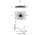
図1から図3には有機溶液の液滴をアミン水溶液層上に滴下したときに生じる液滴状態の変化が示されている。より具体的には、図1はノズルから有機溶液の液滴が滴下し始める段階における液滴状態を示す図面であり、図2はアミン水溶液層に達した直後の液滴状態を示す図面であり、図3は界面重合が完了した状態の液滴状態を示す図面である。それぞれの図面において、(a)は側面図、(b)は上面図、(c)は液滴におけるアシルハライド化合物の濃度勾配または液滴における界面重合の厚さを示すグラフである。 FIG. 1 to FIG. 3 show changes in the droplet state that occur when a droplet of an organic solution is dropped on the amine aqueous solution layer. More specifically, FIG. 1 is a drawing showing a droplet state at a stage where an organic solution droplet starts to drop from a nozzle, and FIG. 2 is a drawing showing a droplet state immediately after reaching the amine aqueous solution layer. FIG. 3 is a drawing showing a droplet state in which interfacial polymerization is completed. In each drawing, (a) is a side view, (b) is a top view, and (c) is a graph showing the concentration gradient of an acyl halide compound in a droplet or the thickness of interfacial polymerization in the droplet.
以下では、図1から図3を参照して滴下方式で形成されたポリアミド活性層の表面状態をより具体的に説明する。 Hereinafter, the surface state of the polyamide active layer formed by the dropping method will be described more specifically with reference to FIGS. 1 to 3.
まず、ノズルから液滴が滴下し始める段階では、アシルハライド化合物132が液滴130内において比較的均一に分散されている(図1を参照)。このように、アシルハライド化合物132を含む液滴130はノズルから滴下されてアミン水溶液層120上に落ちる。液滴130がアミン水溶液層120に達すると、アミン水溶液層の表面に沿って液滴が四方に広がり平坦化する(図2を参照)。このとき、有機溶媒の移動速度が溶質のアシルハライド化合物に比べて速いため、瞬時に相対的に多くのアシルハライド化合物が中心部に存在するようになり、周辺部ではアシルハライド化合物の濃度が相対的に低くなる。また、アミン化合物とアシルハライド化合物の界面重合反応が非常に速く行われるため、液滴内においてアシルハライド濃度が再平衡化される前に界面重合反応がほぼ終わり、その結果、界面重合がほぼ中心部において行われ、周辺部では反応が殆ど生じない。このように、有機溶液を滴下する方式でアミン水溶液層と接触させる場合、アミン化合物とアシルハライド化合物の界面重合がほぼ液滴の中心部において行われ、液滴の外郭部では界面重合が殆ど生じなくなる。即ち、滴下された液滴の平坦化につれ、アミン化合物とアシルハライド化合物の界面重合程度が高い中心部、及びアミン化合物との界面重合程度が弱い領域134(以下、臨界領域とする)が形成されるようになり(図3(a)及び図3(b)を参照)、その結果、図3(c)に示されているように、液滴中心から外郭部に向かって界面重合の厚さ、即ち、ポリアミド活性層の厚さが薄くなる。
First, at the stage where droplets start to drop from the nozzle, the
このように、アシルハライド化合物を含有した有機溶液の液滴をアミン水溶液層上に滴下する方式を用いる場合、液滴中心との距離によってポリアミド活性層の厚さが異なるようになるため、ポリアミド活性層の表面粗度差が大きく、比表面積が増加するようになる。ポリアミド活性層の比表面積が大きいと、水処理分離膜の耐塩素性の減少幅が小さくなって水処理分離膜の塩除去率の機能が長時間持続されるため、比表面積が小さくて平坦な水処理分離膜を使用したときに比べてその交替周期が増加するという効果がある。また、酸処理によって表面粗度を上昇させる方法に比べて表面の負電荷の形成程度が小さく、2次コーティングを行うなどの別途の後処理工程が必要ではないという長所がある。 As described above, when using a method in which a droplet of an organic solution containing an acyl halide compound is dropped on an amine aqueous solution layer, the thickness of the polyamide active layer varies depending on the distance from the center of the droplet. The surface roughness difference of the layer is large, and the specific surface area is increased. If the specific surface area of the polyamide active layer is large, the decrease in the chlorine resistance of the water treatment separation membrane is small and the function of the salt removal rate of the water treatment separation membrane is maintained for a long time, so the specific surface area is small and flat. There is an effect that the alternation period is increased as compared with the case where the water treatment separation membrane is used. In addition, as compared with the method of increasing the surface roughness by acid treatment, the degree of formation of negative charges on the surface is small, and there is an advantage that a separate post-treatment step such as secondary coating is not necessary.
一方、本発明において、上記有機溶液の液滴滴下は、当該技術分野においてよく知られている液滴滴下手段、例えば、スポイト、注射器、噴射ノズルなどによって行われることができる。 On the other hand, in the present invention, the droplet dropping of the organic solution can be performed by a droplet dropping means well known in the art, for example, a dropper, a syringe, a jet nozzle or the like.
一方、本発明において、アミン水溶液層上に滴下される有機溶液の量は、滴下後の有機溶液が平坦化し、自然にアミン水溶液層表面を覆うことができる程度で、活性層表面が平坦化しない程度であることが好ましい。具体的には、本発明において、有機溶液の滴下量は、単位面積1m2当たり50ml〜500ml程度、好ましくは100ml〜400ml程度であることができる。 On the other hand, in the present invention, the amount of the organic solution dropped on the amine aqueous solution layer is such that the organic solution after dropping is flattened and can naturally cover the surface of the amine aqueous solution layer, and the active layer surface is not flattened. It is preferable that it is a grade. Specifically, in the present invention, the dropping amount of the organic solution can be about 50 ml to 500 ml, preferably about 100 ml to 400 ml per 1 m 2 of unit area.
また、本発明において、上記有機溶液の液滴当たりの体積は、0.001ml〜5ml程度、好ましくは0.005ml〜5ml、さらに好ましくは0.01ml〜1ml程度であることができる。有機溶液の液滴当たりの体積が0.001mlより小さいと、ポリアミド活性層が分離膜の表面全体に形成されなくなる可能性があり、有機溶液の液滴当たりの体積が5mlより大きいと、ポリアミド活性層が平坦化して分離膜の比表面積が小さくなるおそれがある。 In the present invention, the volume per droplet of the organic solution may be about 0.001 ml to 5 ml, preferably about 0.005 ml to 5 ml, and more preferably about 0.01 ml to 1 ml. If the volume per droplet of the organic solution is smaller than 0.001 ml, the polyamide active layer may not be formed on the entire surface of the separation membrane, and if the volume per droplet of the organic solution is larger than 5 ml, the polyamide activity The layer may become flat and the specific surface area of the separation membrane may be reduced.
一方、本発明において、上記有機溶液の液滴の滴下間隔は、特に制限されず、規則的な間隔で滴下されてもよく、不規則的な間隔で滴下されてもよい。また、上記有機溶液の液滴の滴下間隔は、滴下方向によって異なってもよく、同一であってもよい。例えば、水処理分離膜の横方向及び縦方向の滴下間隔が同一であってもよく、異なってもよい。また、一方向には液滴を規則的な間隔で滴下し、他方向には不規則的な間隔で滴下してもよい。 On the other hand, in the present invention, the dropping interval of the organic solution droplets is not particularly limited, and may be dropped at regular intervals or may be dropped at irregular intervals. The dropping interval of the organic solution droplets may be different depending on the dropping direction, or may be the same. For example, the horizontal and vertical dropping intervals of the water treatment separation membrane may be the same or different. Further, the droplets may be dropped at regular intervals in one direction and dropped at irregular intervals in the other direction.
有機溶液の液滴が規則的な間隔で滴下される場合、滴下間隔は1mm〜50mm程度であることができ、より好ましくは5mm〜30mm程度であることができる。滴下間隔が上記数値範囲を満たす場合、優れたポリアミド活性層の表面粗度特性を得ることができる。 When the droplets of the organic solution are dropped at regular intervals, the dropping interval can be about 1 mm to 50 mm, more preferably about 5 mm to 30 mm. When the dropping interval satisfies the above numerical range, excellent surface roughness characteristics of the polyamide active layer can be obtained.
また、本発明において、上記有機溶液の液滴は、アミン水溶液層の全面積に対して同時に滴下されることができ、時間間隔を置いて順に滴下されることもできる。また、上記有機溶液の液滴は、第1方向には同時に滴下され、上記第1方向と垂直な第2方向には順に滴下されることができる。 In the present invention, the droplets of the organic solution can be dropped simultaneously with respect to the entire area of the aqueous amine solution layer, or can be dropped sequentially with a time interval. The organic solution droplets may be simultaneously dropped in the first direction and sequentially dropped in a second direction perpendicular to the first direction.
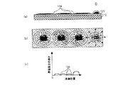
図4から図6には複数の液滴を時間間隔を置いて順に滴下したときの液滴の状態変化が示され、図7から図9には複数の液滴を同時に滴下したときの液滴の状態変化が示されている。 FIG. 4 to FIG. 6 show changes in the state of droplets when a plurality of droplets are sequentially dropped at intervals, and FIGS. 7 to 9 show droplets when a plurality of droplets are dropped simultaneously. The state change is shown.
まず、図4から図6を参照して液滴を順に滴下したときの液滴の状態変化について説明する。図4は第1液滴がアミン水溶液層上に接触され、一定時間経過後、第2液滴がアミン水溶液層上に達したばかりの状態を示す図面であり、図5は第2液滴が平坦化する過程における状態を示す図面であり、図6はいくつかの滴下が行われた後のポリアミド活性層の表面状態を示す図面である。それぞれの図面において、(a)は側面図、(b)は上面図、(c)は液滴におけるアシルハライド化合物の濃度勾配または界面重合の厚さを示すグラフである。 First, with reference to FIGS. 4 to 6, a description will be given of a state change of a droplet when droplets are sequentially dropped. FIG. 4 is a view showing a state in which the first droplet is brought into contact with the amine aqueous solution layer, and the second droplet has just reached the amine aqueous solution layer after a certain period of time, and FIG. FIG. 6 is a diagram showing a surface state of a polyamide active layer after several drops are performed. In each drawing, (a) is a side view, (b) is a top view, and (c) is a graph showing the concentration gradient of an acyl halide compound in a droplet or the thickness of interfacial polymerization.
有機溶液の液滴を一定の時間間隔を置いてアミン水溶液層120上に滴下する場合、後から滴下された液滴130b(便宜上、「第2液滴」とする)がアミン水溶液層120上に達したとき、先に滴下された液滴130a(便宜上、「第1液滴」とする)は、アミン水溶液層との界面重合反応が完了した状態である(図4を参照)。このとき、界面重合反応が完了した第1液滴130aは、図3に示されているように、界面重合程度が高い中心部、及び界面重合程度が低い臨界領域134と、を含む。また、第2液滴130bは、アミン水溶液層120上に達した後、四方に広がり平坦化し始め、その過程において先に滴下された第1液滴130aと重畳(overlap)する領域が発生する(図5を参照)。しかし、この重畳領域は、先に滴下された第1液滴130aによってアミン水溶液層との反応が完了した状態であるか、臨界領域が形成されてアミン水溶液層を覆う状態であるため、重畳領域へ第2液滴に含まれたアシルハライド化合物が導入されても、界面重合反応は殆ど生じない。したがって、第1液滴と第2液滴の重畳部分には、図6(b)に示されているように、臨界領域134が形成され、この部分においてポリアミド活性層の厚さが相対的に薄くなる(図6を参照)。このように、有機溶液の液滴を時間間隔を置いて滴下する場合、界面重合層の厚さが図6(c)に示されている勾配を有するようになり、その結果、相対的に高い表面粗度及び比表面積を有するようになる。また、臨界領域にはポリアミド活性層が殆ど形成されないため、透過流量が向上するという効果も有するようになる。
When drops of the organic solution are dropped on the amine
上記のような液滴の順次滴下は、例えば、アミン水溶液層が形成された多孔性支持体を移動させながら一定の時間間隔を置いて有機溶液の液滴を滴下する方式で行われることができる。この場合、本発明の水処理分離膜は、ポリアミド活性層の形成時に多孔性支持体を移動させながら、アシルハライド化合物を含有する有機溶液の液滴を一定の時間間隔で上記アミン水溶液層上に滴下してポリアミド活性層を形成する段階を含むことができる。 The sequential dropping of the droplets as described above can be performed, for example, by a method of dropping the droplets of the organic solution at regular intervals while moving the porous support on which the aqueous amine solution layer is formed. . In this case, the water treatment separation membrane of the present invention allows the droplets of the organic solution containing the acyl halide compound to move on the amine aqueous solution layer at regular time intervals while moving the porous support during the formation of the polyamide active layer. Dropping to form a polyamide active layer can be included.
ただし、上記のように多孔性支持体を移動させながら液滴を滴下する場合、多孔性支持体の移動方向(即ち、MD方向)の液滴の滴下周期及び多孔性支持体の移動速度により、界面重合が行われない部分が過度に広がって塩除去率が低下したり、ポリアミド活性層が過度に厚くなって透過流量が低下するなどという問題点があり得る。したがって、上記多孔性支持体の移動時間及びMD方向の液滴滴下周期を適切に調節することにより、ポリアミド活性層の形成面積や厚さなどを調節する必要がある。上記多孔性支持体の移動時間及びMD方向の液滴滴下周期は、滴下される液滴の体積、液滴の広がり性、製造しようとする水処理分離膜の物性などを考慮して適宜調節されることができる。好ましくは、下記数式1を満たす範囲で行われることができる。 However, when droplets are dropped while moving the porous support as described above, depending on the droplet dropping period in the moving direction of the porous support (that is, the MD direction) and the moving speed of the porous support, There may be a problem that the portion where the interfacial polymerization is not performed is excessively widened to reduce the salt removal rate, or the polyamide active layer is excessively thick and the permeate flow rate is decreased. Therefore, it is necessary to adjust the formation area and thickness of the polyamide active layer by appropriately adjusting the moving time of the porous support and the droplet dropping period in the MD direction. The moving time of the porous support and the droplet dropping period in the MD direction are appropriately adjusted in consideration of the volume of the dropped droplet, the spreadability of the droplet, the physical properties of the water treatment separation membrane to be manufactured, etc. Can. Preferably, it can be performed in a range satisfying the following mathematical formula 1.
[数1]
0.25R≦v×Δt≦0.75R …[式1]
[Equation 1]
0.25R ≦ v × Δt ≦ 0.75R [Formula 1]
このとき、上記vは多孔性支持体の移動速度、Δtは多孔性支持体の移動方向に沿って滴下される有機溶液の液滴の滴下周期、Rは平坦化した液滴の底面の中心を通過する弦のうち最も長い弦の長さ、即ち、平坦化が完了した液滴の底面の長径を意味する。 At this time, v is the moving speed of the porous support, Δt is the dropping period of the organic solution dropped along the moving direction of the porous support, and R is the center of the bottom surface of the flattened drop. It means the length of the longest string among the passing strings, that is, the major axis of the bottom surface of the droplet that has been flattened.
このとき、上記多孔性支持体の移動速度vとMD方向の液滴滴下周期Δtの積とは、Δtの時間で多孔性支持体が移動した距離を意味する。これは、時間間隔を置いて落下された液滴間の滴下間隔となる。即ち、上記数式1は液滴間の間隔が平坦化が完了した液滴底面の長径の0.25〜0.75倍程度であることを意味する。本発明者らの研究によると、MD方向の液滴間の間隔が上記数値範囲を満たす場合、比表面積、表面粗度、透過流量及び塩除去率の特性がすべて優れることが確認できた。また、生産性を考慮するとき、上記Δtは1/60秒〜1.5秒程度であることがより好ましい。 At this time, the product of the moving speed v of the porous support and the droplet dropping period Δt in the MD direction means the distance that the porous support has moved in the time of Δt. This is a drop interval between droplets dropped at time intervals. That is, the above formula 1 means that the interval between the droplets is about 0.25 to 0.75 times the major axis of the bottom surface of the droplet that has been flattened. According to the study by the present inventors, it was confirmed that the specific surface area, the surface roughness, the permeation flow rate, and the salt removal rate were all excellent when the interval between the droplets in the MD direction satisfied the above numerical range. In consideration of productivity, Δt is more preferably about 1/60 seconds to 1.5 seconds.
また、上記のように多孔性支持体を移動させながら液滴を滴下する場合、上記多孔性支持体の移動方向(MD方向)とともに、上記多孔性支持体の幅方向(TD方向)に沿って滴下される有機溶液の液滴も一定の時間間隔を置いて滴下されることができる。このとき、上記TD方向の液滴が滴下される時間間隔(即ち、滴下周期)は、TD方向に滴下される液滴数や液滴当たりの体積などによって異なるが、生産性を考慮するとき、上記多孔性支持体の幅方向(TD方向)に沿って滴下される有機溶液の液滴の滴下周期は多孔性支持体の移動方向(MD方向)に沿って滴下される有機溶液の液滴の滴下周期より短いことが好ましい。 Moreover, when dropping a droplet while moving the porous support as described above, along the movement direction (MD direction) of the porous support, along the width direction (TD direction) of the porous support. Drops of the organic solution to be dropped can also be dropped at regular time intervals. At this time, the time interval at which the droplets in the TD direction are dropped (that is, the dropping period) varies depending on the number of droplets dropped in the TD direction, the volume per droplet, and the like. The dropping period of the organic solution droplets dropped along the width direction (TD direction) of the porous support is that of the organic solution droplets dropped along the movement direction (MD direction) of the porous support member. it is not preferable shorter than the dropping period.
次に、図7から図9を参照して液滴を同時に滴下したときの液滴の状態変化について説明する。具体的には、図7は同時滴下された有機溶液の液滴がポリアミド活性層上に達したばかりの状態を示す図面であり、図8は有機溶液の液滴が平坦化する過程を示す図面であり、図9は平坦化及び界面重合が完了した状態を示す図面である。それぞれの図面において、(a)は側面図、(b)は上面図、(c)は液滴におけるアシルハライド化合物の濃度勾配または界面重合の厚さを示すグラフである。 Next, referring to FIG. 7 to FIG. 9, the state change of the droplet when the droplet is simultaneously dropped will be described. Specifically, FIG. 7 is a diagram showing a state in which droplets of the organic solution dropped simultaneously on the polyamide active layer are shown, and FIG. 8 is a diagram showing a process in which the droplets of the organic solution are flattened. FIG. 9 is a view showing a state in which planarization and interfacial polymerization are completed. In each drawing, (a) is a side view, (b) is a top view, and (c) is a graph showing the concentration gradient of an acyl halide compound in a droplet or the thickness of interfacial polymerization.
図7から図9に示されているように、同時滴下された液滴は同時に四方に広がり、重畳する部分が形成されるようになる。上記重畳部には、2つの液滴に含まれたアシルハライド化合物がすべて存在するため、アシルハライド化合物の濃度が重畳しない周辺部に比べて相対的に高い(図8(b)を参照)。これにより、液滴中心部だけでなく、液滴と液滴が重なる部分でも界面重合反応が活発に行われ、図8(c)に示されているような厚さ勾配を有するポリアミド活性層が形成されるようになる。即ち、順に滴下された液滴とは異なって、同時滴下された液滴の最外郭部のみに臨界領域134が形成され、液滴の重畳部には臨界領域が形成されなくなる。その結果、時間間隔を置いて滴下された液滴に比べて相対的に粗密なポリアミド活性層が形成されて相対的に高い塩除去率を具現することができる。ただし、表面粗度の増加量は、順次滴下方式に比べて相対的に低下する。
As shown in FIG. 7 to FIG. 9, the simultaneously dropped droplets simultaneously spread in all directions, and an overlapping portion is formed. Since all the acyl halide compounds contained in the two droplets are present in the superimposing portion, the concentration of the acyl halide compound is relatively higher than that in the peripheral portion where the superimposing portion does not overlap (see FIG. 8B). As a result, the interfacial polymerization reaction is actively performed not only in the center of the droplet but also in the portion where the droplet overlaps, and a polyamide active layer having a thickness gradient as shown in FIG. Will be formed. That is, unlike the droplets dropped in order, the
上記で説明した通り、同時滴下及び順次滴下はそれぞれ長所を有するため、水処理分離膜が適用される用途または求められる物性に適合する方式を用いることができる。例えば、高い塩除去率が求められる場合は、全面積同時滴下方式で製造された水処理分離膜を用いることができ、耐塩素性が高く求められる場合は、順次滴下によって製造された水処理分離膜を用いることができる。 As described above, since simultaneous dripping and sequential dripping each have advantages, a method suitable for the application to which the water treatment separation membrane is applied or the required physical properties can be used. For example, when a high salt removal rate is required, a water treatment separation membrane manufactured by the whole area simultaneous dropping method can be used, and when high chlorine resistance is required, a water treatment separation manufactured by sequential dropping is used. A membrane can be used.
また、水処理分離膜の生産性、透過流量及び塩除去率の特性側面において、水処理分離膜の製造時に、一方向、例えば、MD方向には順次滴下を行い、他の方向、例えば、TD方向には同時滴下を行う方法のように、同時滴下及び順次滴下をともに適用することもできる。より具体的には、本発明の上記ポリアミド活性層を形成する段階は、上記多孔性支持体の移動方向(MD方向)に沿って滴下される有機溶液の液滴などを一定の時間間隔を置いて滴下し、上記多孔性支持体の幅方向(TD方向)に沿って滴下される有機溶液の液滴は同時に滴下する方法で行うことができる。 In addition, in terms of the characteristics of productivity, permeation flow rate and salt removal rate of the water treatment separation membrane, when manufacturing the water treatment separation membrane, the water treatment separation membrane is sequentially dropped in one direction, for example, the MD direction, and the other direction, for example, TD. Both simultaneous dripping and sequential dripping can be applied as in the method of simultaneous dripping in the direction. More specifically, in the step of forming the polyamide active layer of the present invention, the organic solution droplets or the like dropped along the moving direction (MD direction) of the porous support are placed at regular intervals. Drops of the organic solution that are dropped along the width direction (TD direction) of the porous support can be simultaneously dropped.
このとき、上記MD方向に沿って滴下される有機溶液の液滴は上記数式1を満たすように滴下されることが好ましく、上記多孔性支持体の幅方向(TD方向)に沿って滴下される有機溶液の液滴の滴下間隔(D)は下記数式2を満たすようにすることが好ましい。 At this time, the droplet of the organic solution dropped along the MD direction is preferably dropped so as to satisfy the above mathematical formula 1, and is dropped along the width direction (TD direction) of the porous support. It is preferable that the dropping interval (D) of the droplets of the organic solution satisfy the following formula 2.
[数2]
R'≦D≦3/16(R2h) …[式2]
[Equation 2]
R ′ ≦ D ≦ 3/16 (R 2 h) ... [Formula 2]
このとき、R'は液滴がアミン水溶液層に達する直前の液滴の長径、Dは幅方向に沿って滴下される液滴の滴下間隔、Rは平坦化が完了した有機溶液の液滴の底面の長径、hは平坦化が完了した有機溶液の液滴の高さである。 At this time, R ′ is the major axis of the droplet just before the droplet reaches the amine aqueous solution layer, D is the dropping interval of the droplets dropped along the width direction, and R is the droplet of the organic solution that has been flattened. The major axis of the bottom surface, h, is the height of the droplet of the organic solution that has been flattened.
ここで、上記「長径」とは、液滴の中心を通過する弦のうち最も長い弦の長さを意味し、上記液滴の滴下間隔(D)はスポイト、ノズルのような液滴滴下手段の配置間隔で測定されることができる。具体的には、上記液滴の滴下間隔(D)は、1mm〜50mm程度であることができ、例えば、1mm〜30mm、10mm〜30mm、または20mm〜40mm程度であることができる。 Here, the “major axis” means the length of the longest string among the strings passing through the center of the droplet, and the droplet dropping interval (D) is a droplet dropping means such as a dropper or a nozzle. Can be measured at intervals of. Specifically, the drop interval (D) of the droplets can be about 1 mm to 50 mm, for example, about 1 mm to 30 mm, 10 mm to 30 mm, or about 20 mm to 40 mm.
図10には上記のような水処理分離膜の製造方法を具現するための製造装置の一具現例が示されている。図10のように、本発明による水処理分離膜の製造方法は、有機溶液を貯蔵する有機溶液貯蔵タンク10、アミン水溶液層上に有機溶液の液滴を滴下するための液滴滴下手段20、アミン水溶液層が形成された多孔性支持体50を移動させる移動手段30と、乾燥手段40と、を含む装置を用いて具現されることができる。このとき、上記液滴滴下手段20は、多孔性支持体の幅方向(TD方向)に複数の液滴を同時に滴下できるように構成されることが好ましい。
FIG. 10 shows an embodiment of a manufacturing apparatus for implementing the method for manufacturing a water treatment separation membrane as described above. As shown in FIG. 10, the water treatment separation membrane manufacturing method according to the present invention includes an organic
上記のような滴下方式で製造された本発明の水処理分離膜のポリアミド活性層は、滴下された液滴が平坦化して形成されたアミン化合物との界面重合度が高い中心部、及びアミン化合物との界面重合度が低い臨界領域を有するようになる。このとき、上記中心部及び臨界領域は、界面重合度の差異によって界面重合の厚さが異なるようになる。その結果、ポリアミド活性層の全面積において類似した界面重合度を有する従来のポリアミド系水処理分離膜に比べて高い活性層の表面粗度を有するようになる。より具体的には、本発明による水処理分離膜は、ポリアミド活性層表面の算術平均粗度(Ra)が60nm〜100nm程度と高く、その結果、長時間の使用後にも耐塩素性の減少程度が少ないため優れた透過流量及び塩除去特性を示す。このとき、上記算術平均粗度(Ra)は、例えば、AFM(Digital Instruments Nanoscope V MMAFM−8 Multimode)を用いて測定することができる。 The polyamide active layer of the water treatment separation membrane of the present invention produced by the dropping method as described above has a central portion having a high degree of interfacial polymerization with an amine compound formed by flattening the dropped droplet, and an amine compound And has a critical region where the degree of interfacial polymerization is low. At this time, the thickness of the interfacial polymerization differs depending on the degree of interfacial polymerization between the central portion and the critical region. As a result, the surface roughness of the active layer is higher than that of a conventional polyamide water treatment separation membrane having a similar degree of interfacial polymerization in the entire area of the polyamide active layer. More specifically, the water treatment separation membrane according to the present invention has a high arithmetic average roughness (Ra) on the surface of the polyamide active layer of about 60 nm to 100 nm, and as a result, the degree of decrease in chlorine resistance even after prolonged use. Excellent permeation flow rate and salt removal characteristics. At this time, the arithmetic average roughness (Ra) can be measured using, for example, AFM (Digital Instruments Nanoscope V MMAFM-8 Multimode).
一方、本発明者らは、本発明による水処理分離膜のポリアミド活性層における重合度偏差を確認するために、以下のような実験を行った。まず、ポリアミド活性層の表面をHCl溶液で酸処理し、ポリアミド活性層に存在する−COCl基をすべて−COOHで置換した。その後、フーリエ変換赤外線分光器を用いて上記酸処理されたポリアミド活性層表面のIRデータを測定した。測定されたIRデータを用いて、アミド基と結合したC=O二重結合(−CONH−)のピーク高さに対するカルボキシ基のC=O二重結合(−COOH)のピーク高さの比を測定した。 On the other hand, the present inventors conducted the following experiment in order to confirm the polymerization degree deviation in the polyamide active layer of the water treatment separation membrane according to the present invention. First, the surface of the polyamide active layer was acid-treated with an HCl solution, and all —COCl groups present in the polyamide active layer were replaced with —COOH. Thereafter, IR data of the surface of the above-mentioned acid-treated polyamide active layer was measured using a Fourier transform infrared spectrometer. Using the measured IR data, the ratio of the peak height of the C═O double bond (—COOH) of the carboxy group to the peak height of the C═O double bond (—CONH—) bound to the amide group is calculated. It was measured.
上記実験において、上記フーリエ変換赤外線分光器としては、ATR(Ge)FT−IR装置のFTS−7000(製造社:Varian)を使用しており、アミド基と結合したC=O二重結合のピークは1663cm−1近傍、カルボキシ基のC=O二重結合のピークは1709cm−1近傍で示された。 In the above experiment, as the Fourier transform infrared spectrometer, FTS-7000 (manufacturer: Varian) of an ATR (Ge) FT-IR apparatus is used, and the peak of the C═O double bond bonded to the amide group. the 1663Cm -1 vicinity, C = O double bond peaks of the carboxy group shown in 1709 cm -1 vicinity.
上記実験の結果、本発明のように滴下方式によって製造された水処理分離膜のポリアミド活性層の場合、アミド基と結合したC=O二重結合のピーク高さに対するカルボキシ基のC=O二重結合のピーク高さの比の最小値に対する最大値の比が1.2〜4程度、好ましくは1.5〜4程度と示された。 As a result of the above experiment, in the case of the polyamide active layer of the water treatment separation membrane produced by the dropping method as in the present invention, the C═O 2 of the carboxy group with respect to the peak height of the C═O double bond bonded to the amide group. The ratio of the maximum value with respect to the minimum value of the peak height ratio of the double bond was shown to be about 1.2 to 4, preferably about 1.5 to 4.
一方、本発明において、上記アミド基と結合したC=O二重結合のピーク高さに対するカルボキシ基のC=O二重結合のピーク高さの比の最小値に対する最大値の比は、少なくとも5cm×5cm以上の面積、例えば、5cm×5cm、10cm×10cm、または15cm×15cmの面積に対して測定されたIRデータを用いて計算されることが好ましい。このとき、IRデータの測定間隔は、横方向及び縦方向にそれぞれ1mm〜10mm程度、例えば、1mm〜5mm、または3mm〜10mm程度であることが好ましい。 On the other hand, in the present invention, the ratio of the maximum value to the minimum value of the ratio of the peak height of the C═O double bond of the carboxy group to the peak height of the C═O double bond bonded to the amide group is at least 5 cm. It is preferably calculated using IR data measured for an area of x5 cm or more, for example, an area of 5 cm x 5 cm, 10 cm x 10 cm, or 15 cm x 15 cm. At this time, the measurement interval of the IR data is preferably about 1 mm to 10 mm, for example, about 1 mm to 5 mm, or about 3 mm to 10 mm in the horizontal direction and the vertical direction, respectively.
より具体的には、本発明の水処理分離膜は、上述のように、ポリアミド活性層に滴下された液滴が平坦化してアミン化合物との界面重合度が高い中心部、及びアミン化合物との界面重合度が低い臨界領域が形成されるが、上記臨界領域では界面重合によって形成されるアミド基の比率が低いため、アミド基と結合したC=O二重結合のピーク高さに対するカルボキシ基のC=O二重結合のピーク高さの比が高く示され、上記中心部では相対的にアミド基の比率が高いためアミド基と結合したC=O二重結合のピーク高さに対するカルボキシ基のC=O二重結合のピーク高さの比が低く示される。例えば、本発明の水処理分離膜では、上記臨界領域において示されるアミド基と結合したC=O二重結合のピーク高さに対するカルボキシ基のC=O二重結合のピーク高さの比(即ち、最大値)が0.17〜0.19程度であることができ、上記中心部において示されるアミド基と結合したC=O二重結合のピーク高さに対するカルボキシ基のC=O二重結合のピーク高さの比(即ち、最小値)が0.05〜0.07程度であることができる。 More specifically, as described above, the water treatment separation membrane of the present invention comprises a central portion having a high degree of interfacial polymerization with an amine compound by flattening the droplets dropped on the polyamide active layer, and the amine compound. A critical region having a low degree of interfacial polymerization is formed. In the critical region, the ratio of amide groups formed by interfacial polymerization is low, so the carboxy group has a peak height of the C═O double bond bonded to the amide group. The ratio of the peak height of the C═O double bond is high, and the ratio of the amide group relative to the peak height of the C═O double bond bonded to the amide group is relatively high in the above central portion. The ratio of the peak height of the C═O double bond is shown low. For example, in the water treatment separation membrane of the present invention, the ratio of the peak height of the C═O double bond of the carboxy group to the peak height of the C═O double bond bonded to the amide group shown in the critical region (ie, , The maximum value) can be about 0.17 to 0.19, and the C═O double bond of the carboxy group with respect to the peak height of the C═O double bond bound to the amide group shown in the center portion. The peak height ratio (i.e., the minimum value) can be about 0.05 to 0.07.
これに対し、アシルハライド有機溶液をアミン水溶液上に塗布または浸漬する方式でポリアミド活性層を形成する従来の水処理分離膜の場合は、ポリアミド活性層においてアミド基と結合したC=O二重結合のピーク高さに対するカルボキシ基のC=O二重結合のピーク高さの比の最小値に対する最大値の比が非常に低く示された。より具体的には、上記従来の水処理分離膜の場合、ポリアミド活性層の全面積においてアミド基と結合したC=O二重結合のピーク高さに対するカルボキシ基のC=O二重結合のピーク高さの比は0.13〜0.16と比較的均一に示され、アミド基と結合したC=O二重結合のピーク高さに対するカルボキシ基のC=O二重結合のピーク高さの比の最小値に対する最大値の比は1.13程度であった。 On the other hand, in the case of a conventional water treatment separation membrane in which a polyamide active layer is formed by applying or immersing an acyl halide organic solution on an amine aqueous solution, a C═O double bond bonded to an amide group in the polyamide active layer. The ratio of the maximum value to the minimum value of the ratio of the peak height of the C═O double bond of the carboxy group to the peak height of was very low. More specifically, in the case of the conventional water treatment separation membrane, the peak of the C═O double bond of the carboxy group with respect to the peak height of the C═O double bond bonded to the amide group in the entire area of the polyamide active layer. The ratio of the height is relatively uniformly shown as 0.13 to 0.16, which is the peak height of the C═O double bond of the carboxy group to the peak height of the C═O double bond bonded to the amide group. The ratio of the maximum value to the minimum value of the ratio was about 1.13.
以上で説明した通り、本発明による水処理分離膜のポリアミド活性層の場合、位置によって重合度の偏差が大きく、その結果、表面粗度及び活性比表面積が広くて耐塩素性の持続時間が高くなり、長時間の高い塩除去率及び透過流量を維持することができる。 As described above, in the case of the polyamide active layer of the water treatment separation membrane according to the present invention, the deviation of the degree of polymerization is large depending on the position. As a result, the surface roughness and the active specific surface area are wide and the duration of chlorine resistance is high. Thus, a long salt removal rate and permeate flow rate can be maintained for a long time.
一方、本発明の水処理分離膜は、上記ポリアミド活性層を0.5%のローダミンB(Rhodamine B)水溶液(Sigma aldrich社)で染色したとき、上記ポリアミド活性層の少なくとも一部領域に2つ以上の弧(arc)が互いに連結されて形成される曲線型パターンが少なくとも一つ以上現れる。このとき、上記「弧(arc)」とは、二つの点をつなぐ曲線を意味し、両終点と両終点をつなぐ曲線部からなる。例えば、上記弧(arc)は、これに限定されないが、円、楕円などのような円形閉曲線の一部であることができる。このとき、上記円形の閉曲線は一つの液滴が滴下された後、平坦化して形成される構造物の底面状を示すもので、円に係る数学的な定義(即ち、中心からの距離が同一の点の集まり)を満たすもののみを意味するのではなく、円と類似した形状の閉曲線、例えば、楕円、半円、歪んだ円形、またはでこぼこの閉曲線をすべて含む概念で理解されなければならない。また、上記曲線型パターンを形成するそれぞれの円形閉曲線の形状は、同一であっても、異なってもよい。 On the other hand, in the water treatment separation membrane of the present invention, when the polyamide active layer is dyed with a 0.5% Rhodamine B aqueous solution (Sigma aldrich), two of the polyamide active layers are present in at least a partial region of the polyamide active layer. At least one curved pattern formed by connecting the above arcs to each other appears. At this time, the “arc” means a curve connecting two points, and is composed of both end points and a curved portion connecting both end points. For example, the arc may be a part of a closed circular curve such as, but not limited to, a circle, an ellipse, and the like. At this time, the circular closed curve indicates the bottom surface of the structure formed by flattening after one droplet is dropped, and the mathematical definition of the circle (ie, the same distance from the center). Should be understood as a concept that includes all closed curves of a shape similar to a circle, such as an ellipse, a semicircle, a distorted circle, or a bumpy closed curve. In addition, the shape of each circular closed curve forming the curved pattern may be the same or different.
一方、上記円形閉曲線の長径は、液滴の滴下間隔、有機溶液内のアシルハライド化合物の濃度、滴下される液滴当たりの体積などによって異なることができる。また、これに制限されないが、水処理分離膜の物性を考慮するとき、5mm〜100mm程度であることが好ましく、15mm〜35mm程度であることがより好ましい。 On the other hand, the major axis of the circular closed curve may vary depending on the dropping interval of the droplets, the concentration of the acyl halide compound in the organic solution, the volume per dropped droplet, and the like. Moreover, although not restricted to this, when the physical property of a water treatment separation membrane is considered, it is preferable that it is about 5 mm-100 mm, and it is more preferable that it is about 15 mm-35 mm.
また、上記円形閉曲線の中心間の距離は、一般的に液滴滴下間隔と類似して形成され、好ましくは1mm〜50mm程度、例えば、1mm〜30mm、10mm〜30mm、または20mm〜40mm程度であることができる。一方、本発明において、上記円形閉曲線の中心とは、液滴が滴下される位置に対応する点を意味する。 Further, the distance between the centers of the circular closed curves is generally formed similar to the droplet dropping interval, and is preferably about 1 mm to 50 mm, for example, about 1 mm to 30 mm, 10 mm to 30 mm, or about 20 mm to 40 mm. be able to. On the other hand, in the present invention, the center of the circular closed curve means a point corresponding to a position where a droplet is dropped.
なお、本発明において、上記円形閉曲線は、規則的または不規則的に配列されることができる。このとき、上記曲線型パターンを形成する円形閉曲線の配列は液滴の滴下間隔によって異なるため、滴下間隔を調節することにより、所望する形状のパターンを形成することができる。 In the present invention, the closed circular curve can be regularly or irregularly arranged. At this time, since the arrangement of the circular closed curves forming the curved pattern differs depending on the droplet dropping interval, a pattern having a desired shape can be formed by adjusting the dropping interval.
一方、本発明において、上記曲線型パターンは、その厚さが上記円形閉曲線の長径の4%〜25%程度であることが好ましい。このとき、上記曲線型パターンの厚さとは、染色によって認知される曲線の平均線幅を意味する。円形閉曲線の長径及び厚さが上記範囲を満たす場合、高い表面粗度及び浄水性能を得ることができる。 On the other hand, in the present invention, the curved pattern preferably has a thickness of about 4% to 25% of the major axis of the circular closed curve. At this time, the thickness of the curved pattern means the average line width of the curve recognized by staining. When the major axis and thickness of the circular closed curve satisfy the above range, high surface roughness and water purification performance can be obtained.
一方、上記曲線型パターンはポリアミド重合度が低い臨界領域に現れる。これは、臨界領域の重合度が低いためポリアミド活性層がそれほど緻密ではない構造で形成され、重合度が高い領域、即ち、ポリアミド活性層が緻密に形成された領域に比べて染料による吸着が充分に行われて相対的に円滑に染色されるためである。即ち、上記染色によって現れるパターンは、本発明による水処理分離膜のポリアミド活性層に重合度が特に低い臨界領域が存在することを示す。 On the other hand, the curved pattern appears in a critical region where the degree of polyamide polymerization is low. This is because the polyamide active layer is formed with a structure that is not so dense because the degree of polymerization in the critical region is low, and the adsorption by the dye is sufficient compared to the region where the degree of polymerization is high, that is, the region where the polyamide active layer is densely formed. This is because the dyeing is performed relatively smoothly. That is, the pattern appearing by the dyeing indicates that a critical region having a particularly low degree of polymerization exists in the polyamide active layer of the water treatment separation membrane according to the present invention.
上記曲線型パターンは、液滴の滴下方式及び滴下間隔によってその形状が異なって現れることができる。図11には本発明のような滴下方式によって製造された水処理分離膜のポリアミド活性層をローダミンB水溶液で染色したときに現れるパターン形状が示されている。 The curved pattern may appear differently depending on the droplet dropping method and the dropping interval. FIG. 11 shows a pattern shape that appears when a polyamide active layer of a water treatment separation membrane produced by a dropping method as in the present invention is dyed with a rhodamine B aqueous solution.
図11(a)は多孔性支持体をMD方向に移動させながらTD方向及びMD方向に液滴を順に滴下する場合に現れるパターン形状を示すものである。本発明において、上記曲線型パターンは、図11(a)に示されているように、各弧の両終点が他の弧の曲線部と連結された形態であることができる。このとき、上記2つ以上の弧は、同一方向(例えば、下方向)に膨らむように配列されることが好ましい。 FIG. 11A shows a pattern shape that appears when droplets are sequentially dropped in the TD direction and the MD direction while moving the porous support in the MD direction. In the present invention, as shown in FIG. 11A, the curved pattern may have a form in which both end points of each arc are connected to a curved portion of another arc. At this time, the two or more arcs are preferably arranged so as to swell in the same direction (for example, downward).
また、図11(b)は液滴滴下時にTD方向に液滴を一定間隔で同時滴下し、MD方向に液滴を順次滴下した場合に現れるパターン形状を示すものである。図11(b)に示されているように、本発明の上記曲線型パターンは、2つ以上の弧(arc)が一列に配列され、隣接した弧(arc)がそれぞれの弧の終点で連結された形態で形成されることができる。このとき、上記2つ以上の弧は、同一方向(例えば、下方向)に膨らむように配列されることが好ましく、上記2つ以上の弧の配列方向(即ち、TD方向)に対して垂直方向(即ち、MD方向)に沿って曲線型パターンが繰り返し現れることもできる。 FIG. 11B shows a pattern shape that appears when droplets are simultaneously dropped at a constant interval in the TD direction and droplets are sequentially dropped in the MD direction. As shown in FIG. 11 (b), the curved pattern of the present invention has two or more arcs arranged in a line and adjacent arcs connected at the end of each arc. Can be formed. At this time, it is preferable that the two or more arcs are arranged so as to swell in the same direction (for example, the downward direction), and a direction perpendicular to the arrangement direction of the two or more arcs (that is, the TD direction). A curved pattern can repeatedly appear along (that is, in the MD direction).
また、図面に示されてはいないが、水処理分離膜の全面積に対して液滴を同時に滴下する場合は、ポリアミド活性層の中央部分にはパターンが現れず、4面の最外郭の縁のみに曲線型パターンが現れることもできる。より具体的には、2つ以上の弧(arc)がMD方向に沿って一列に配列され、隣接した弧(arc)がそれぞれの弧の終点で連結された形態の曲線型パターンが2つ、及び2つ以上の弧(arc)がTD方向に一列に配列され、隣接した弧(arc)がそれぞれの弧の終点で連結された形態の曲線型パターンが2つ現れることができる。 Although not shown in the drawings, when droplets are dropped simultaneously over the entire area of the water treatment separation membrane, no pattern appears in the central portion of the polyamide active layer, and the outermost edges of the four surfaces Only a curved pattern can appear. More specifically, two curvilinear patterns in which two or more arcs are arranged in a line along the MD direction and adjacent arcs are connected at the end of each arc, And two or more curved patterns in which two or more arcs are arranged in a line in the TD direction and adjacent arcs are connected at the end points of the respective arcs can appear.
一方、図12にはアミン水溶液層上にアシルハライド有機溶液をスロット−コーティング方式で塗布して形成されたポリアミド活性層をローダミンB水溶液で染色した後の撮影写真が示されている。図12に示されているように、従来の方式によって製造されたポリアミド活性層の場合、ローダミンB水溶液で染色しても、特別なパターンが現れないことが分かる。 On the other hand, FIG. 12 shows a photograph taken after dyeing a polyamide active layer formed by applying an acyl halide organic solution on an amine aqueous solution layer by a slot-coating method with a rhodamine B aqueous solution. As shown in FIG. 12, in the case of the polyamide active layer produced by the conventional method, it can be seen that no special pattern appears even when dyed with an aqueous rhodamine B solution.
一方、上記のような本発明の水処理分離膜としては、精密濾過膜(Micro Filtration)、限外濾過膜(Ultra Filtration)、ナノ濾過膜(Nano Filtration)、または逆浸透膜(Reverse Osmosis)などが用いられることができ、逆浸透膜が用いられることが特に好ましい。 Meanwhile, examples of the water treatment separation membrane of the present invention as described above include a microfiltration membrane, an ultrafiltration membrane, a nanofiltration membrane, and a reverse osmosis membrane. It is particularly preferred that a reverse osmosis membrane is used.
本発明は、上記本発明による水処理分離膜を少なくとも一つ以上含む水処理モジュールを提供する。上記本発明による水処理モジュールの具体的な種類は、特に制限されないが、板型(plate&frame)モジュール、管型(tubular)モジュール、中空糸型(Hollow&Fiber)モジュール、または渦巻型(spiral wound)モジュールなどが含まれる。また、本発明の水処理モジュールは、上述の本発明の水処理分離膜を含む限り、その他の構成や製造方法などは特に制限されず、当業界において公知の一般的な手段を制限なく採用することができる。 The present invention provides a water treatment module comprising at least one water treatment separation membrane according to the present invention. The specific type of the water treatment module according to the present invention is not particularly limited, but includes a plate-type module, a tubular module, a hollow-fiber module, a spiral-wound module, and the like. Is included. Moreover, as long as the water treatment module of the present invention includes the above-described water treatment separation membrane of the present invention, other configurations and manufacturing methods are not particularly limited, and general means known in the art are employed without limitation. be able to.
上記のような本発明の水処理モジュールは、家庭用/産業用浄水装置、下水処理装置、海淡水処理装置に有用に用いられることができる。 The water treatment module of the present invention as described above can be usefully used in household / industrial water purification devices, sewage treatment devices, and sea fresh water treatment devices.
以下では、具体的な実施例を挙げて本発明をより詳細に説明する。 Hereinafter, the present invention will be described in more detail with reference to specific examples.
実施例1
DMF(N,N−ジメチルホルムアミド)溶液に18重量%のポリスルホン固形分を入れて80℃〜85℃において12時間以上溶かすことで、均一の液相を得た。この溶液をポリエステル材質の厚さ95〜100μmを有する不織布上に厚さ45〜50μmでキャストして多孔性ポリスルホン支持体を形成した。
Example 1
A uniform liquid phase was obtained by adding 18% by weight of polysulfone solids in a DMF (N, N-dimethylformamide) solution and dissolving at 80 ° C. to 85 ° C. for 12 hours or more. This solution was cast on a non-woven fabric having a thickness of 95-100 μm made of polyester material at a thickness of 45-50 μm to form a porous polysulfone support.
上記方法によって製造された多孔性ポリスルホン支持体を2重量%のメタフェニレンジアミン、1重量%のトリエチルアミン、及び2.3重量%のカンファースルホン酸を含む水溶液に2分間入れてから取り出した後、支持体上における過剰の水溶液を25psiのローラーを用いて除去し、常温で1分間乾燥した。 The porous polysulfone support produced by the above method was placed in an aqueous solution containing 2% by weight of metaphenylenediamine, 1% by weight of triethylamine, and 2.3% by weight of camphorsulfonic acid, taken out for 2 minutes, and then supported. Excess aqueous solution on the body was removed using a 25 psi roller and dried at room temperature for 1 minute.
次に、非極性有機溶媒(炭素数5個〜12個のアルカン化合物)のISOL−C(CAS No.64741−66−8、SKC製造)に0.1体積%のトリメソイルクロライドを含有した有機溶液をアミン水溶液層が形成された多孔性支持体の上部に、上記多孔性支持体を線速1m/minで移動させ、上記多孔性支持体1m2当たり100mlの量で滴下した。このとき、有機溶液の液滴当たりの体積は0.01mlであった。多孔性支持体の幅方向に1cmの間隔で液滴を同時滴下し、移動方向に1.7回/secの周期で液滴を滴下した。滴下後、60℃のオーブンにおいて10分間乾燥して水処理分離膜を製造した。 Next, an organic material containing 0.1% by volume of trimesoyl chloride in ISOL-C (CAS No. 64741-66-8, manufactured by SKC), a nonpolar organic solvent (alkane compound having 5 to 12 carbon atoms). The solution was moved onto the porous support on which the aqueous amine solution layer was formed, the porous support was moved at a linear velocity of 1 m / min, and dropped in an amount of 100 ml per 1 m 2 of the porous support. At this time, the volume per droplet of the organic solution was 0.01 ml. Droplets were simultaneously dropped at an interval of 1 cm in the width direction of the porous support, and the droplets were dropped at a cycle of 1.7 times / sec in the moving direction. After dripping, it was dried in an oven at 60 ° C. for 10 minutes to produce a water treatment separation membrane.
実施例2
有機溶液の滴下体積を液滴当たり0.05mlとし、多孔性支持体の移動方向に0.34回/secの周期で液滴を滴下した点を除いては、実施例1と同一方法で水処理分離膜を製造した。
Example 2
Except that the dropping volume of the organic solution was 0.05 ml per droplet and the droplet was dropped at a cycle of 0.34 times / sec in the moving direction of the porous support, the same method as in Example 1 was used. A treated separation membrane was produced.
実施例3
有機溶液の滴下体積を液滴当たり0.1mlとし、多孔性支持体の移動方向に0.17回/secの周期で液滴を滴下した点を除いては、実施例1と同一方法で水処理分離膜を製造した。
Example 3
Water was dropped in the same manner as in Example 1 except that the dropping volume of the organic solution was 0.1 ml per droplet and the droplet was dropped at a cycle of 0.17 times / sec in the direction of movement of the porous support. A treated separation membrane was produced.
実施例4
有機溶液の滴下体積を液滴当たり0.2mlとし、多孔性支持体の移動方向に0.09回/secの周期で液滴を滴下した点を除いては、実施例1と同一方法で水処理分離膜を製造した。
Example 4
Except that the dropping volume of the organic solution was 0.2 ml per droplet and the droplet was dropped at a cycle of 0.09 times / sec in the moving direction of the porous support, the same method as in Example 1 was used. A treated separation membrane was produced.
実施例5
多孔性支持体1m2当たり200mlの有機溶液を滴下し、有機溶液の滴下体積を液滴当たり0.02mlにして滴下した点を除いては、実施例1と同一方法で水処理分離膜を製造した。
Example 5
A water treatment separation membrane is produced in the same manner as in Example 1 except that 200 ml of organic solution is dropped per 1 m 2 of the porous support and the dropping volume of the organic solution is dropped to 0.02 ml per droplet. did.
実施例6
多孔性支持体1m2当たり200mlの有機溶液を滴下し、有機溶液の滴下体積を液滴当たり0.1mlにして滴下した点を除いては、実施例2と同一方法で水処理分離膜を製造した。
Example 6
A water treatment separation membrane was produced in the same manner as in Example 2 except that 200 ml of an organic solution was dropped per 1 m 2 of the porous support, and the dropping volume of the organic solution was dropped to 0.1 ml per droplet. did.
実施例7
多孔性支持体1m2当たり200mlの有機溶液を滴下し、有機溶液の滴下体積を液滴当たり0.2mlにして滴下した点を除いては、実施例3と同一方法で水処理分離膜を製造した。
Example 7
A water treatment separation membrane was produced in the same manner as in Example 3 except that 200 ml of organic solution was dropped per 1 m 2 of the porous support, and the dropping volume of the organic solution was dropped to 0.2 ml per droplet. did.
実施例8
多孔性支持体1m2当たり200mlの有機溶液を滴下し、有機溶液の滴下体積を液滴当たり0.4mlにして滴下した点を除いては、実施例4と同一方法で水処理分離膜を製造した。
Example 8
A water treatment separation membrane was produced in the same manner as in Example 4 except that 200 ml of the organic solution was dropped per 1 m 2 of the porous support and the dropping volume of the organic solution was dropped to 0.4 ml per droplet. did.
実施例9
アミン水溶液層が形成された多孔性支持体の移動速度を2m/minとし、多孔性支持体1m2当たり200mlの有機溶液を滴下した点を除いては、実施例3と同一にして実験を行った。
Example 9
The experiment was conducted in the same manner as in Example 3 except that the moving speed of the porous support on which the amine aqueous solution layer was formed was 2 m / min, and 200 ml of an organic solution was dropped per 1 m 2 of the porous support. It was.
実施例10
アミン水溶液層が形成された多孔性支持体の移動速度を2m/minとし、多孔性支持体1m2当たり200mlの有機溶液を滴下した点を除いては、実施例4と同一にして実験を行った。
Example 10
The experiment was conducted in the same manner as in Example 4 except that the moving speed of the porous support on which the amine aqueous solution layer was formed was 2 m / min and 200 ml of an organic solution was dropped per 1 m 2 of the porous support. It was.
実施例11
DMF(N,N−ジメチルホルムアミド)溶液に18重量%のポリスルホン固形分を入れて80℃〜85℃において12時間以上溶かすことで、均一な液相を得た。この溶液をポリエステル材質の厚さ95〜100μmの不織布上に厚さ45〜50μmでキャストして多孔性ポリスルホン支持体を形成した。
Example 11
A uniform liquid phase was obtained by adding 18% by weight of polysulfone solid in a DMF (N, N-dimethylformamide) solution and dissolving at 80 ° C. to 85 ° C. for 12 hours or more. This solution was cast at a thickness of 45 to 50 μm on a non-woven fabric of a polyester material having a thickness of 95 to 100 μm to form a porous polysulfone support.
上記方法によって製造された多孔性ポリスルホン支持体を2重量%のメタフェニレンジアミン、1重量%のトリエチルアミン、及び2.3重量%のカンファースルホン酸を含む水溶液に2分間入れてから取り出した後、支持体上における過剰の水溶液を25psiのローラを用いて除去し、常温で1分間乾燥した。 The porous polysulfone support produced by the above method was placed in an aqueous solution containing 2% by weight of metaphenylenediamine, 1% by weight of triethylamine, and 2.3% by weight of camphorsulfonic acid, taken out for 2 minutes, and then supported. Excess aqueous solution on the body was removed using a 25 psi roller and dried at room temperature for 1 minute.
次に、非極性有機溶媒(炭素数5個〜12個のアルカン化合物)のISOL−C(CAS No.64741−66−8、SKC製造)に0.1体積%のトリメソイルクロライドを含有した有機溶液をアミン水溶液層が塗布された多孔性支持体の上部に、噴射ノズルによって同時滴下して界面重合反応させた。このとき、上記有機溶液は、多孔性支持体の表面積1m2当たり250mlの量で滴下された。液滴当たりの体積は0.005ml、滴下面積は10cm×10cmであった。滴下後、60℃のオーブンにおいて10分間乾燥してコーティング層を形成した。 Next, an organic material containing 0.1% by volume of trimesoyl chloride in ISOL-C (CAS No. 64741-66-8, manufactured by SKC), a nonpolar organic solvent (alkane compound having 5 to 12 carbon atoms). The solution was simultaneously dropped onto the upper part of the porous support coated with the aqueous amine layer by an injection nozzle to cause an interfacial polymerization reaction. At this time, the organic solution was dropped in an amount of 250 ml per 1 m 2 of the surface area of the porous support. The volume per droplet was 0.005 ml, and the dropping area was 10 cm × 10 cm. After dripping, it was dried in an oven at 60 ° C. for 10 minutes to form a coating layer.
実施例12
有機溶液の滴下体積を液滴当たり0.01mlとし、その他の条件は実施例11と同一にして実験を行った。
Example 12
The experiment was conducted under the same conditions as in Example 11 except that the dropping volume of the organic solution was 0.01 ml per droplet.
実施例13
有機溶液の滴下体積を液滴当たり0.02mlとし、その他の条件は実施例11と同一にして実験を行った。
Example 13
The experiment was conducted under the same conditions as in Example 11 except that the dropping volume of the organic solution was 0.02 ml per droplet.
実施例14
有機溶液の滴下体積を液滴当たり0.03mlとし、その他の条件は実施例11と同一にして実験を行った。
Example 14
The experiment was conducted under the same conditions as in Example 11 except that the dropping volume of the organic solution was 0.03 ml per droplet.
実施例15
有機溶液の滴下体積を液滴当たり0.05mlとし、その他の条件は実施例11と同一にして実験を行った。
Example 15
The experiment was conducted under the same conditions as in Example 11 except that the dropping volume of the organic solution was 0.05 ml per droplet.
実施例16
有機溶液の滴下体積を液滴当たり0.07mlとし、その他の条件は実施例11と同一にして実験を行った。
Example 16
The experiment was conducted under the same conditions as in Example 11 except that the dropping volume of the organic solution was 0.07 ml per droplet.
実施例17
有機溶液の滴下体積を液滴当たり0.1mlとし、その他の条件は実施例11と同一にして実験を行った。
Example 17
The experiment was conducted under the same conditions as in Example 11 except that the dropping volume of the organic solution was 0.1 ml per droplet.
実施例18
有機溶液の滴下体積を液滴当たり0.15mlとし、その他の条件は実施例11と同一にして実験を行った。
Example 18
The experiment was performed under the same conditions as in Example 11 except that the dropping volume of the organic solution was 0.15 ml per droplet.
実施例19
機溶液の滴下体積を液滴当たり2.0mlとし、その他の条件は実施例11と同一にして実験を行った。
Example 19
The experiment was conducted under the same conditions as in Example 11 except that the dropping volume of the machine solution was 2.0 ml per droplet.
比較例
DMF(N,N−ジメチルホルムアミド)溶液に18重量%のポリスルホン固形分を入れて80℃〜85℃において12時間溶かして均一な液相を得た。この溶液をポリエステル材質の厚さ95〜100μmの不織布上に厚さ45〜50μmでキャストして多孔性ポリスルホン支持体を形成した。
Comparative Example 18% by weight of polysulfone solid content was placed in a DMF (N, N-dimethylformamide) solution and dissolved at 80 ° C. to 85 ° C. for 12 hours to obtain a uniform liquid phase. This solution was cast at a thickness of 45 to 50 μm on a non-woven fabric of a polyester material having a thickness of 95 to 100 μm to form a porous polysulfone support.
上記方法によって製造された多孔性ポリスルホン支持体を2重量%のメタフェニレンジアミン、1重量%のトリエチルアミン、及び2.3重量%のカンファースルホン酸を含む水溶液に2分間入れてから取り出した後、支持体上における過剰の水溶液を25psiのローラを用いて除去し、常温で1分間乾燥した。 The porous polysulfone support produced by the above method was placed in an aqueous solution containing 2% by weight of metaphenylenediamine, 1% by weight of triethylamine, and 2.3% by weight of camphorsulfonic acid, taken out for 2 minutes, and then supported. Excess aqueous solution on the body was removed using a 25 psi roller and dried at room temperature for 1 minute.
次に、非極性有機溶媒(炭素数5個〜12個のアルカン化合物)のISOL−C(CAS No.64741−66−8、SKC製造)に0.1体積%のトリメソイルクロライドを含有した有機溶液をアミン水溶液が塗布された多孔性支持体の上部に均一に塗布して界面重合反応させた。 Next, an organic material containing 0.1% by volume of trimesoyl chloride in ISOL-C (CAS No. 64741-66-8, manufactured by SKC), a nonpolar organic solvent (alkane compound having 5 to 12 carbon atoms). The solution was uniformly applied to the upper part of the porous support coated with the aqueous amine solution to cause an interfacial polymerization reaction.
塗布後、60℃のオーブンにおいて10分間乾燥してコーティング層を形成した。 After application, the coating layer was formed by drying in an oven at 60 ° C. for 10 minutes.
実験例1−浄水性能の評価
上記実施例1〜19及び比較例によって製造された逆浸透膜の初期塩除去率及び初期透過流量を800psiの圧力下において測定した。初期塩除去率及び初期透過流量は25℃において32,000ppmの塩化ナトリウム水溶液を4500mL/minの流量で供給しながら測定した。膜の評価に用いられた逆浸透膜セル装置は、平板型透過セル、高圧ポンプ、貯蔵槽及び冷却装置を備える。また、平板型透過セルの構造は、クロスフロー(cross−flow)方式で、有効透過面積は28cm2である。次に、洗浄された逆浸透分離膜を透過セルに設置した後、評価装備の安定化のために、3次蒸留水を用いて約1時間の予備運転を十分に行った。その後、32,000ppmの塩化ナトリウム水溶液に交替して圧力及び透過流量が正常状態に達するまで約1時間の装備運転を行った後、10分の間に透過される水の量を測定して流量を計算し、伝導度メーター(Conductivity Meter)を用いて透過前後の塩濃度を分析して塩除去率を計算した。測定結果は下記表1に示した通りである。
Experimental Example 1 Evaluation of Water Purification Performance The initial salt removal rate and the initial permeation flow rate of the reverse osmosis membranes produced by Examples 1 to 19 and the comparative example were measured under a pressure of 800 psi. The initial salt removal rate and the initial permeation flow rate were measured at 25 ° C. while supplying a 32,000 ppm sodium chloride aqueous solution at a flow rate of 4500 mL / min. The reverse osmosis membrane cell device used for the evaluation of the membrane includes a flat plate type permeation cell, a high-pressure pump, a storage tank, and a cooling device. Further, the structure of the flat plate-type transmission cell is a cross-flow method, and the effective transmission area is 28 cm 2 . Next, after the washed reverse osmosis separation membrane was installed in the permeation cell, a preliminary operation for about 1 hour was sufficiently performed using tertiary distilled water in order to stabilize the evaluation equipment. After that, the equipment was operated for about 1 hour until the pressure and permeate flow rate reached a normal state by switching to a 32,000 ppm sodium chloride aqueous solution, and then the flow rate was measured by measuring the amount of water permeated for 10 minutes. The salt removal rate was calculated by analyzing the salt concentration before and after permeation using a conductivity meter (Conductivity Meter). Measurement results are shown in Table 1 below.

上記表1によると、有機溶液をアミン水溶液層が形成された多孔性支持体上に滴下させる方法によって製造された実施例1〜19の水処理分離膜の場合、均一な塗布によって製造された比較例に比べて優れた透過流量特性及び塩除去率を有することが分かる。これは、液滴が自由落下して支持層内部の深いところまで有機溶液が浸透することができるため、支持層表面の気孔内により粗密なポリアミド層を形成し、ポリアミド層表面では高い活性比表面積を有するためである。 According to Table 1 above, in the case of the water treatment separation membranes of Examples 1 to 19 manufactured by a method of dropping an organic solution onto a porous support on which an aqueous amine solution layer was formed, a comparison manufactured by uniform coating It can be seen that it has excellent permeation flow characteristics and salt removal rate compared to the examples. This is because the droplet can fall freely and the organic solution can penetrate deep into the inside of the support layer, so that a denser polyamide layer is formed in the pores on the surface of the support layer, and the surface of the polyamide layer has a high active specific surface area. It is for having.
実験例2−時間による耐塩素性の評価
実施例2、実施例14及び比較例によって製造された逆浸透膜を評価した。32,000ppmのNaCl水溶液及び2,000ppmのNaOClを含有する混合水溶液を用いて800psiにおける初期塩除去率及び初期透過流量を測定した後、6時間経過後及び12時間経過後の塩除去率及び初期透過流量を測定した。測定結果は表2に示した通りである。
Experimental Example 2 Evaluation of Chlorine Resistance by Time The reverse osmosis membranes produced by Example 2, Example 14 and Comparative Example were evaluated. After measuring the initial salt removal rate and initial permeate flow rate at 800 psi using a mixed aqueous solution containing 32,000 ppm NaCl aqueous solution and 2,000 ppm NaOCl, the salt removal rate and initial value after 6 hours and 12 hours passed. The permeate flow rate was measured. The measurement results are as shown in Table 2.
上記表2によると、比較例の場合、NaOClに6時間及び12時間露出した後の塩除去率の減少量がそれぞれ4.59%、22.7%であるのに対し、実施例2の場合はNaOClに露出した6時間及び12時間後の塩除去率の減少量がそれぞれ0.16%、0.27%、実施例14の場合はそれぞれ3.3%、3.87%であった。即ち、本発明による水処理分離膜の場合、塩素露出による浄水特性が比較例に比べて非常に少ないことが確認できた。 According to Table 2 above, in the case of the comparative example, the reduction amount of the salt removal rate after exposure to NaOCl for 6 hours and 12 hours is 4.59% and 22.7%, respectively. The decrease in the salt removal rate after 6 hours and 12 hours exposed to NaOCl was 0.16% and 0.27%, respectively, and in Example 14, 3.3% and 3.87%, respectively. That is, in the case of the water treatment separation membrane according to the present invention, it was confirmed that the water purification characteristics due to chlorine exposure were very small compared to the comparative example.
実験例3−表面粗度の測定
実施例14、実施例15、実施例17及び比較例によって製造された水処理分離膜で5μm×5μmのサイズを有する試料を製作し、AFM(Digital Instruments Nanoscope V MMAFM−8 Multimode)を用いて試料全体のサイズに対して粗度分析(Roughness Analysis)を行い、Ra値を測定した。測定結果は表3に示した通りである。
Experimental Example 3 Measurement of Surface Roughness A sample having a size of 5 μm × 5 μm was manufactured using the water treatment separation membranes manufactured according to Examples 14, 15, 15 and 17 and AFM (Digital Instruments Nanoscope V). Roughness analysis (Roughness Analysis) was performed on the size of the entire sample using MMAFM-8 Multimode, and the Ra value was measured. The measurement results are as shown in Table 3.
表3の結果によると、本発明の製造方法によって形成された水処理分離膜の算術平均粗度(Ra)値が比較例の水処理分離膜に比べて大きいことが分かる。 According to the result of Table 3, it turns out that the arithmetic mean roughness (Ra) value of the water treatment separation membrane formed by the manufacturing method of this invention is large compared with the water treatment separation membrane of a comparative example.
実験例4−IRデータの分析
実施例2及び比較例によって製造された水処理分離膜を5cm×5cmのサイズに裁断し、試料を製作した後、上記試料をHCl溶液に入れて酸処理した。次に、ATR(Ge)FT−IR装置のFTS7000(製造社:Varian)を用いて、上記のように処理された試料の表面において横及び縦5mmの間隔でIRデータを測定し、アミド基と結合したC=O二重結合のピーク高さに対するカルボキシ基のC=O二重結合のピーク高さの比を計算し、計算された値の最小値及び最大値を確認した。結果は下記表4に示した通りである。
Experimental Example 4-Analysis of IR data The water treatment separation membrane produced in Example 2 and the comparative example was cut into a size of 5 cm x 5 cm, and a sample was prepared. Then, the sample was put in an HCl solution and acid-treated. Next, using an ATR (Ge) FT-IR apparatus FTS7000 (manufacturer: Varian), IR data was measured at intervals of 5 mm in the horizontal and vertical directions on the surface of the sample treated as described above. The ratio of the peak height of the C═O double bond of the carboxy group to the peak height of the bound C═O double bond was calculated, and the minimum and maximum values of the calculated values were confirmed. The results are as shown in Table 4 below.
上記表4によると、実施例2によるポリアミド活性層の場合、位置によってアミン化合物とアシルハライド化合物の重合程度が非常に大きいのに対し、比較例によるポリアミド活性層の重合程度は全面積において比較的均一であることが分かる。 According to Table 4 above, in the case of the polyamide active layer according to Example 2, the degree of polymerization of the amine compound and the acyl halide compound is very large depending on the position, whereas the degree of polymerization of the polyamide active layer according to the comparative example is relatively large in the entire area. It turns out that it is uniform.
10 有機溶液貯蔵タンク
20 滴下手段
30 移動手段
40 乾燥手段
50 アミン水溶液層が形成された多孔性支持体
130、130a、130b 有機溶液の液滴
132 アシルハライド化合物
134 臨界領域
DESCRIPTION OF
Claims (11)
前記ポリアミド活性層を5%のローダミンB水溶液で染色したとき、前記ポリアミド活性層の少なくとも一部領域に2つ以上の弧(arc)が連結されて形成される曲線型パターンが少なくとも一つ以上現れ、
前記弧(arc)は円形閉曲線の一部であり、
前記円形閉曲線は長径が5mm〜100mmであり、
前記円形閉曲線の中心間の距離が1mm〜50mmである、
水処理分離膜。 A polyamide active layer is formed on the porous support;
When the polyamide active layer is dyed with 5% rhodamine B aqueous solution, at least one curved pattern formed by connecting two or more arcs to at least a partial region of the polyamide active layer is present. And
The arc is part of a circular closed curve;
The circular closed curve has a major axis of 5 mm to 100 mm,
The distance between the centers of the circular closed curves is 1 mm to 50 mm,
Water treatment separation membrane.
請求項1に記載の水処理分離膜。 The curved pattern has a form in which both end points of each arc are connected to a curved portion of another arc (arc).
The water treatment separation membrane according to claim 1.
請求項1又は請求項2に記載の水処理分離膜。 The curved pattern is a form in which the two or more arcs are arranged in a line and adjacent arcs are connected at the end points of the respective arcs.
The water treatment separation membrane according to claim 1 or claim 2.
請求項2または3に記載の水処理分離膜。 The two or more arcs are arranged to swell in the same direction;
The water treatment separation membrane according to claim 2 or 3.
請求項3に記載の水処理分離膜。 The curvilinear pattern repeatedly appears along a direction perpendicular to an arrangement direction of the two or more arcs;
The water treatment separation membrane according to claim 3.
請求項1から請求項5までの何れか1項に記載の水処理分離膜。 The circular closed curves are irregularly or regularly arranged;
The water treatment separation membrane according to any one of claims 1 to 5 .
請求項1から請求項6までの何れか1項に記載の水処理分離膜。 The curved pattern has a thickness of 4% to 25% of the major axis of the circular closed curve.
The water treatment separation membrane according to any one of claims 1 to 6 .
請求項1から請求項7までの何れか1項に記載の水処理分離膜。 The curved pattern appears in a critical region where the degree of polyamide polymerization is low,
The water treatment separation membrane according to any one of claims 1 to 7 .
請求項1から請求項8までの何れか1項に記載の水処理分離膜。 The arithmetic average roughness of the surface of the polyamide active layer is 60 nm to 100 nm.
The water treatment separation membrane according to any one of claims 1 to 8 .
水処理モジュール。 Including at least one water treatment separation membrane according to any one of claims 1 to 9 ,
Water treatment module.
水処理装置。 Including at least one water treatment module according to claim 10 ;
Water treatment equipment.
Applications Claiming Priority (7)
| Application Number | Priority Date | Filing Date | Title |
|---|---|---|---|
| KR20120132550 | 2012-11-21 | ||
| KR10-2012-0132550 | 2012-11-21 | ||
| KR20130004147 | 2013-01-14 | ||
| KR10-2013-0004147 | 2013-01-14 | ||
| KR10-2013-0142098 | 2013-11-21 | ||
| PCT/KR2013/010643 WO2014081232A1 (en) | 2012-11-21 | 2013-11-21 | High-flow water treatment separation membrane having superior chlorine resistance |
| KR1020130142098A KR101578582B1 (en) | 2012-11-21 | 2013-11-21 | High flux water-treatment membrane with high chlorine resistance |
Publications (2)
| Publication Number | Publication Date |
|---|---|
| JP2015510451A JP2015510451A (en) | 2015-04-09 |
| JP5872075B2 true JP5872075B2 (en) | 2016-03-01 |
Family
ID=50892290
Family Applications (3)
| Application Number | Title | Priority Date | Filing Date |
|---|---|---|---|
| JP2014557583A Active JP5872075B2 (en) | 2012-11-21 | 2013-11-21 | High flow rate water treatment separation membrane, water treatment module and water treatment device with excellent chlorine resistance |
| JP2014556499A Active JP6029156B2 (en) | 2012-11-21 | 2013-11-21 | High flow rate water treatment separation membrane with excellent chlorine resistance |
| JP2014557582A Active JP5875201B2 (en) | 2012-11-21 | 2013-11-21 | High flow rate water treatment separation membrane with excellent chlorine resistance |
Family Applications After (2)
| Application Number | Title | Priority Date | Filing Date |
|---|---|---|---|
| JP2014556499A Active JP6029156B2 (en) | 2012-11-21 | 2013-11-21 | High flow rate water treatment separation membrane with excellent chlorine resistance |
| JP2014557582A Active JP5875201B2 (en) | 2012-11-21 | 2013-11-21 | High flow rate water treatment separation membrane with excellent chlorine resistance |
Country Status (7)
| Country | Link |
|---|---|
| US (2) | US9370751B2 (en) |
| EP (3) | EP2762223B1 (en) |
| JP (3) | JP5872075B2 (en) |
| KR (3) | KR101578582B1 (en) |
| CN (3) | CN104039430B (en) |
| ES (2) | ES2632275T3 (en) |
| WO (3) | WO2014081232A1 (en) |
Families Citing this family (9)
| Publication number | Priority date | Publication date | Assignee | Title |
|---|---|---|---|---|
| WO2014069786A1 (en) * | 2012-11-05 | 2014-05-08 | 주식회사 엘지화학 | Polyamide-based water treatment separating film having superior contamination resistance and method for manufacturing same |
| KR101627930B1 (en) * | 2013-09-16 | 2016-06-07 | 주식회사 엘지화학 | Water-treatment membranes having ion-exchangeable polymer layer and manufacturing method thereof |
| EP3162432A4 (en) * | 2014-06-30 | 2018-02-28 | Toray Industries, Inc. | Composite semipermeable membrane |
| US20170136422A1 (en) * | 2014-06-30 | 2017-05-18 | Toray Industries, Inc. | Composite semipermeable membrane |
| KR101716045B1 (en) * | 2014-09-30 | 2017-03-22 | 주식회사 엘지화학 | Manufacturing method for polyamide watertreatment membranes having properies of high flux and water-treatment membranes manufactured by using the same |
| KR102250387B1 (en) * | 2018-06-21 | 2021-05-10 | 주식회사 엘지화학 | Method for quantifying amine compound forming active layer of separation membrane before preparing it, method for quantifying polyamide or residue amine compound in active layer of separation membrane, and methode for determining creteria for determing conditions or conditions for preparing active layer of separation membrane |
| KR102216547B1 (en) * | 2019-05-09 | 2021-02-17 | 숙명여자대학교산학협력단 | Method and apparatus for generating aerosols |
| CN112221356B (en) * | 2019-07-15 | 2022-07-12 | 中国石油化工股份有限公司 | Chlorine-resistant reverse osmosis membrane and preparation method and application thereof |
| CN115768550A (en) * | 2020-06-29 | 2023-03-07 | 旭化成株式会社 | Composite hollow fiber membrane module and method for producing same |
Family Cites Families (49)
| Publication number | Priority date | Publication date | Assignee | Title |
|---|---|---|---|---|
| US3827564A (en) * | 1973-01-12 | 1974-08-06 | Culligan Int Co | Reverse osmosis membrane module |
| US4277344A (en) | 1979-02-22 | 1981-07-07 | Filmtec Corporation | Interfacially synthesized reverse osmosis membrane |
| JPS62213806A (en) * | 1986-03-13 | 1987-09-19 | Toray Ind Inc | Semi-permeable composite membrane |
| US4765897A (en) * | 1986-04-28 | 1988-08-23 | The Dow Chemical Company | Polyamide membranes useful for water softening |
| JPH05146654A (en) * | 1991-11-29 | 1993-06-15 | Nitto Denko Corp | Dual reverse osmosis membrane |
| JPH07171362A (en) * | 1993-12-21 | 1995-07-11 | Nitto Denko Corp | Composite reverse osmosis membrane |
| EP0772488B1 (en) * | 1994-07-28 | 2001-01-31 | Millipore Corporation | Porous composite membrane and process |
| US5614099A (en) * | 1994-12-22 | 1997-03-25 | Nitto Denko Corporation | Highly permeable composite reverse osmosis membrane, method of producing the same, and method of using the same |
| JP3454295B2 (en) * | 1995-07-05 | 2003-10-06 | 日東電工株式会社 | How to treat tap water |
| JP3588886B2 (en) * | 1996-01-12 | 2004-11-17 | 東レ株式会社 | Method and apparatus for producing composite reverse osmosis membrane |
| KR19980068304A (en) | 1997-02-17 | 1998-10-15 | 한형수 | Performance Improvement Method of Polyamide Reverse Osmosis Composite Membrane |
| JPH10337454A (en) | 1997-04-10 | 1998-12-22 | Nitto Denko Corp | Reverse osmotic multipie membrane and reverse osmosis treatment of water using the same |
| US6413425B1 (en) | 1997-04-10 | 2002-07-02 | Nitto Denko Corporation | Reverse osmosis composite membrane and reverse osmosis treatment method for water using the same |
| US6536605B2 (en) | 1997-06-06 | 2003-03-25 | Koch Membrane Systems, Inc. | High performance composite membrane |
| DE69814891T2 (en) * | 1997-07-02 | 2004-05-13 | Nitto Denko Corp., Ibaraki | COMPOSED REVERSE OSMOSMEMBRANE AND METHOD FOR THE PRODUCTION THEREOF |
| US6015495A (en) * | 1998-02-18 | 2000-01-18 | Saehan Industries Incorporation | Composite polyamide reverse osmosis membrane and method of producing the same |
| US6162358A (en) * | 1998-06-05 | 2000-12-19 | Nl Chemicals Technologies, Inc. | High flux reverse osmosis membrane |
| JP4058657B2 (en) * | 1998-10-05 | 2008-03-12 | 東洋紡績株式会社 | Method for inspecting leak of selectively permeable membrane module |
| US6368507B1 (en) * | 1998-10-14 | 2002-04-09 | Saekan Industries Incorporation | Composite polyamide reverse osmosis membrane and method of producing the same |
| JP2001038175A (en) * | 1999-05-27 | 2001-02-13 | Toyobo Co Ltd | Composite semipermeable membrane |
| US20030136727A1 (en) | 1999-05-27 | 2003-07-24 | Hideki Yamada | Composite semipermeable membrane |
| JP2001286741A (en) * | 2000-04-04 | 2001-10-16 | Toray Ind Inc | Reverse osmosis composite membrane and manufacturing method therefor |
| US6337018B1 (en) * | 2000-04-17 | 2002-01-08 | The Dow Chemical Company | Composite membrane and method for making the same |
| KR100409017B1 (en) * | 2000-06-23 | 2003-12-06 | 주식회사 엘지화학 | Multi-component composite membrane and method for preparing the same |
| KR20050004788A (en) * | 2002-03-01 | 2005-01-12 | 지이 오스모닉스, 인크. | A process for preparing semipermeable membranes having improved permeability |
| KR100516209B1 (en) * | 2003-12-22 | 2005-09-23 | 한국화학연구원 | Method for preparation of highly permeable composite polyamide nanofiltration membranes |
| CN100588451C (en) * | 2004-10-04 | 2010-02-10 | 日东电工株式会社 | Process for producing composite reverse osmosis membrane |
| JP4656511B2 (en) | 2004-10-04 | 2011-03-23 | 日東電工株式会社 | Method for producing composite reverse osmosis membrane |
| US7479300B2 (en) * | 2005-03-30 | 2009-01-20 | Woongjin Chemical Co., Ltd. | Composite polyamide reverse osmosis membrane and method of producing the same |
| KR100813908B1 (en) * | 2005-07-27 | 2008-03-18 | 한국화학연구원 | Preparation method of highly permeable composite polyamide nanofiltration membranes |
| US8602222B2 (en) | 2005-12-16 | 2013-12-10 | Toray Industries, Inc. | Composite semipermeable membranes, methods for production thereof and uses thereof |
| KR100905901B1 (en) | 2006-09-07 | 2009-07-02 | 웅진코웨이주식회사 | Amine aqueous solution for forming an active layer of polyamide reverse osmosis composite membrane, polyamide reverse osmosis composite membrane prepared thereby, and preparation method thereof |
| JP2008080255A (en) * | 2006-09-28 | 2008-04-10 | Nippon Rensui Co Ltd | Pure water making apparatus |
| CA2667579A1 (en) | 2006-10-27 | 2008-05-15 | The Regents Of The University Of California | Micro-and nanocomposite support structures for reverse osmosis thin film membranes |
| JP5131028B2 (en) * | 2007-05-30 | 2013-01-30 | 東レ株式会社 | Manufacturing method of composite semipermeable membrane |
| WO2009035415A1 (en) * | 2007-09-10 | 2009-03-19 | National University Of Singapore | Polymeric membranes incorporating nanotubes |
| US8177978B2 (en) | 2008-04-15 | 2012-05-15 | Nanoh20, Inc. | Reverse osmosis membranes |
| US8147735B2 (en) * | 2008-07-09 | 2012-04-03 | Eltron Research & Development, Inc. | Semipermeable polymers and method for producing same |
| US7815987B2 (en) * | 2008-12-04 | 2010-10-19 | Dow Global Technologies Inc. | Polyamide membrane with coating of polyalkylene oxide and polyacrylamide compounds |
| US8580341B2 (en) * | 2009-05-22 | 2013-11-12 | General Electric Company | Method of making composite membrane |
| JP5377452B2 (en) * | 2009-10-16 | 2013-12-25 | 日東電工株式会社 | Manufacturing method of composite semipermeable membrane |
| KR20110083275A (en) * | 2010-01-14 | 2011-07-20 | 웅진코웨이주식회사 | Membrane for removing endocrine disruptors and fabrication method thereof |
| KR100990168B1 (en) | 2010-07-16 | 2010-10-29 | 한국과학기술연구원 | Forward osmosis membranes and method for fabricating the same |
| KR20130100318A (en) * | 2010-09-30 | 2013-09-10 | 제너럴 일렉트릭 캄파니 | Thin film composite membranes incorporating carbon nanotubes |
| US8591741B2 (en) * | 2010-09-30 | 2013-11-26 | General Electric Company | Thin film composite membranes incorporating carbon nanotubes |
| SG189983A1 (en) * | 2010-10-26 | 2013-06-28 | Toray Industries | Separation membrane, separation membrane element and separation membrane production method |
| EP2637773B1 (en) | 2010-11-10 | 2019-10-30 | NanoH2O Inc. | Improved hybrid tfc ro membranes with non-metallic additives |
| JP2012143750A (en) * | 2010-12-24 | 2012-08-02 | Toray Ind Inc | Method for producing composite semi-permeable membrane |
| US20130146530A1 (en) * | 2011-12-08 | 2013-06-13 | General Electric Company | Membrane, water treatment system, and method of making |
-
2013
- 2013-11-21 CN CN201380003881.6A patent/CN104039430B/en active Active
- 2013-11-21 JP JP2014557583A patent/JP5872075B2/en active Active
- 2013-11-21 JP JP2014556499A patent/JP6029156B2/en active Active
- 2013-11-21 WO PCT/KR2013/010643 patent/WO2014081232A1/en unknown
- 2013-11-21 KR KR1020130142098A patent/KR101578582B1/en active IP Right Grant
- 2013-11-21 WO PCT/KR2013/010637 patent/WO2014081228A1/en active Application Filing
- 2013-11-21 CN CN201380003879.9A patent/CN103958037B/en active Active
- 2013-11-21 JP JP2014557582A patent/JP5875201B2/en active Active
- 2013-11-21 ES ES13843067.3T patent/ES2632275T3/en active Active
- 2013-11-21 EP EP13843068.1A patent/EP2762223B1/en active Active
- 2013-11-21 EP EP13843067.3A patent/EP2886187B1/en active Active
- 2013-11-21 KR KR1020130142100A patent/KR101530780B1/en active IP Right Grant
- 2013-11-21 KR KR1020130142099A patent/KR101583117B1/en active IP Right Grant
- 2013-11-21 ES ES13843066.5T patent/ES2690326T3/en active Active
- 2013-11-21 EP EP13843066.5A patent/EP2759333B1/en active Active
- 2013-11-21 CN CN201380003890.5A patent/CN104053494B/en active Active
- 2013-11-21 WO PCT/KR2013/010640 patent/WO2014081230A1/en active Application Filing
-
2014
- 2014-04-24 US US14/260,506 patent/US9370751B2/en active Active
- 2014-04-29 US US14/264,864 patent/US9259691B2/en active Active
Also Published As
Similar Documents
| Publication | Publication Date | Title |
|---|---|---|
| JP5872075B2 (en) | High flow rate water treatment separation membrane, water treatment module and water treatment device with excellent chlorine resistance | |
| KR101682759B1 (en) | Preparing method for polyamide reverse osmosis membrane having properties of high salt rejection and high flux and reverse osmosis membrane manufactured by using the same | |
| JP5978998B2 (en) | Composite semipermeable membrane, composite semipermeable membrane element, and method for producing composite semipermeable membrane | |
| US20080203013A1 (en) | Oxidation-resistant composite reverse osmosis membrane | |
| US9211507B2 (en) | Water-treatment separating membrane of high flux having good chlorine resistance and method of manufacturing the same | |
| JP2014509562A (en) | Reverse osmosis membrane including silver nanowire layer and method for producing the same | |
| EP2859938B1 (en) | Highly permeable carbodiimide comprising reverse osmosis membrane and method for preparing same | |
| KR101114668B1 (en) | Manufacturing method for polyamide-based reverse osmosis membrane and polyamide-based reverse osmosis membrane manufactured thereby | |
| CN107922610B (en) | Composition for interfacial polymerization of polyamide and method for manufacturing reverse osmosis membrane using the same | |
| JP2014500144A (en) | Method for producing reverse osmosis separation membrane and reverse osmosis separation membrane produced thereby | |
| JP2016068019A (en) | Composite semipermeable membrane and manufacturing method for the same, and spiral type separation membrane | |
| KR102079845B1 (en) | Method for manufacturing water-treatment separation membrane, water-treatment separation membrane manufactured by using the same, and composition for manufacturing water-treatment separation membrane | |
| KR102337164B1 (en) | Excellent removing nitrate polyamide reverse osmosis membrane, Method of manufacturing the same and Membrane module comprising the same | |
| JP7403524B2 (en) | Composite hollow fiber membrane and method for manufacturing composite hollow fiber membrane | |
| JP2008259983A (en) | Manufacturing method of dry composite semi-permeable membrane | |
| KR102212132B1 (en) | Separation membrane, composition for active layer of separation membrane, and method for separation membrane | |
| KR102547346B1 (en) | Excellent removing nitrate polyamide reverse osmosis membrane, method of manufacturing the same and membrane module comprising the same | |
| JP2014004565A (en) | Separation membrane and manufacturing method thereof | |
| KR101520150B1 (en) | Reverse osmosis membrane with high flux and manufacturing method thereof | |
| KR20110079141A (en) | Manufacturing method of polyamide composite membrane and composite membrane thereby |
Legal Events
| Date | Code | Title | Description |
|---|---|---|---|
| A977 | Report on retrieval |
Free format text: JAPANESE INTERMEDIATE CODE: A971007 Effective date: 20150729 |
|
| A131 | Notification of reasons for refusal |
Free format text: JAPANESE INTERMEDIATE CODE: A131 Effective date: 20150818 |
|
| A521 | Request for written amendment filed |
Free format text: JAPANESE INTERMEDIATE CODE: A523 Effective date: 20151116 |
|
| TRDD | Decision of grant or rejection written | ||
| A01 | Written decision to grant a patent or to grant a registration (utility model) |
Free format text: JAPANESE INTERMEDIATE CODE: A01 Effective date: 20151215 |
|
| A61 | First payment of annual fees (during grant procedure) |
Free format text: JAPANESE INTERMEDIATE CODE: A61 Effective date: 20160112 |
|
| R150 | Certificate of patent or registration of utility model |
Ref document number: 5872075 Country of ref document: JP Free format text: JAPANESE INTERMEDIATE CODE: R150 |
|
| R250 | Receipt of annual fees |
Free format text: JAPANESE INTERMEDIATE CODE: R250 |
|
| R250 | Receipt of annual fees |
Free format text: JAPANESE INTERMEDIATE CODE: R250 |
|
| R250 | Receipt of annual fees |
Free format text: JAPANESE INTERMEDIATE CODE: R250 |
|
| R250 | Receipt of annual fees |
Free format text: JAPANESE INTERMEDIATE CODE: R250 |
|
| R250 | Receipt of annual fees |
Free format text: JAPANESE INTERMEDIATE CODE: R250 |
|
| R250 | Receipt of annual fees |
Free format text: JAPANESE INTERMEDIATE CODE: R250 |