JP5862005B2 - Solar cell module mounting structure and solar cell unit - Google Patents
Solar cell module mounting structure and solar cell unit Download PDFInfo
- Publication number
- JP5862005B2 JP5862005B2 JP2010247543A JP2010247543A JP5862005B2 JP 5862005 B2 JP5862005 B2 JP 5862005B2 JP 2010247543 A JP2010247543 A JP 2010247543A JP 2010247543 A JP2010247543 A JP 2010247543A JP 5862005 B2 JP5862005 B2 JP 5862005B2
- Authority
- JP
- Japan
- Prior art keywords
- solar cell
- top plate
- cell module
- metal fitting
- plate portion
- Prior art date
- Legal status (The legal status is an assumption and is not a legal conclusion. Google has not performed a legal analysis and makes no representation as to the accuracy of the status listed.)
- Expired - Fee Related
Links
Images


Classifications
-
- Y—GENERAL TAGGING OF NEW TECHNOLOGICAL DEVELOPMENTS; GENERAL TAGGING OF CROSS-SECTIONAL TECHNOLOGIES SPANNING OVER SEVERAL SECTIONS OF THE IPC; TECHNICAL SUBJECTS COVERED BY FORMER USPC CROSS-REFERENCE ART COLLECTIONS [XRACs] AND DIGESTS
- Y02—TECHNOLOGIES OR APPLICATIONS FOR MITIGATION OR ADAPTATION AGAINST CLIMATE CHANGE
- Y02B—CLIMATE CHANGE MITIGATION TECHNOLOGIES RELATED TO BUILDINGS, e.g. HOUSING, HOUSE APPLIANCES OR RELATED END-USER APPLICATIONS
- Y02B10/00—Integration of renewable energy sources in buildings
- Y02B10/10—Photovoltaic [PV]
-
- Y—GENERAL TAGGING OF NEW TECHNOLOGICAL DEVELOPMENTS; GENERAL TAGGING OF CROSS-SECTIONAL TECHNOLOGIES SPANNING OVER SEVERAL SECTIONS OF THE IPC; TECHNICAL SUBJECTS COVERED BY FORMER USPC CROSS-REFERENCE ART COLLECTIONS [XRACs] AND DIGESTS
- Y02—TECHNOLOGIES OR APPLICATIONS FOR MITIGATION OR ADAPTATION AGAINST CLIMATE CHANGE
- Y02E—REDUCTION OF GREENHOUSE GAS [GHG] EMISSIONS, RELATED TO ENERGY GENERATION, TRANSMISSION OR DISTRIBUTION
- Y02E10/00—Energy generation through renewable energy sources
- Y02E10/50—Photovoltaic [PV] energy
Landscapes
- Roof Covering Using Slabs Or Stiff Sheets (AREA)
- Photovoltaic Devices (AREA)
Description
この発明は、太陽電池モジュールの取付け構造に関するものであり、特に折板屋根の山部へ太陽電池モジュールを固定する金具の構造に関するものである。 The present invention relates to a solar cell module mounting structure, and more particularly to a metal fitting structure for fixing a solar cell module to a mountain portion of a folded plate roof.
特許文献1には屋根固定金具が開示されている。屋根固定金具の金具本体は、一対の側壁部を有しており、ボルト軸部を有している。一対の側壁部は折り曲げ成形されている。一方の側壁部には、固定用ボルトを介して補助金具が取り付けられている。他方の側壁部および補助金具が折板屋根の山部を側面から挟む。これにより屋根固定金具は、屋根に固定される。金具本体は上方に突出するボルト軸部を有している。太陽電池モジュールはこのボルト軸部に固定される。
特許文献2には他の屋根固定金具が開示されている。固定ベースは天板および左右一対の側板で構成される。各側板にはボルトが取り付けられている。このボルトは折版屋根の山部に設けられた凹部を両側から挟む。これにより固定ベースは屋根に固定される。天板には取付ボルトが上方に突出している。太陽電池モジュールはこの取付ボルトに固定される。
特許文献1および特許文献2に記載された屋根固定金具は、2本以上のボルトを用いて太陽電池モジュールを屋根に固定している。1本のボルトは太陽電池モジュールを固定金具に固定するために用いる。他のボルトは固定金具を屋根に取り付けるために用いる。太陽電池モジュールは上方に突出したボルトを用いて屋根固定金具に固定される。屋根固定金具を屋根に固定する作業は、屋根固定金具の側面からボルトを締めて行う。
The roof fixing metal fittings described in
太陽電池モジュールは屋根の上に複数のモジュールが配置されることが一般的である。工場の屋根に設置する場合、数百枚の太陽電池モジュールが屋根の上に設置される。固定金具が所定の位置に固定されていない場合、太陽電池モジュールを取り外して、固定金具の位置を再調整する。固定金具の位置の再調整は、側面のボルトを緩めてから行う。このように太陽電池モジュールを屋根に固定する作業は煩雑となる。 As for a solar cell module, it is common that a plurality of modules are arranged on a roof. When installed on the roof of a factory, several hundred solar cell modules are installed on the roof. If the fixture is not fixed in place, the solar cell module is removed and the position of the fixture is readjusted. Readjust the fixing bracket position after loosening the bolts on the side. Thus, the operation | work which fixes a solar cell module to a roof becomes complicated.
この発明は、上記の課題を解決するためになされたものである。この発明は、作業性を改善した太陽電池モジュールの固定金具を提供することを目的とする。 The present invention has been made to solve the above problems. An object of the present invention is to provide a solar cell module fixing bracket with improved workability.
この発明に係る太陽電池モジュールの取り付け構造は、太陽電池モジュールを設置部に取り付けるための太陽電池モジュールの取付け構造において、第1の天板部および前記第1の天板部の両端に接続されて同一方向に延在する一対の第1の側板部を有し、前記第1の側板部の先端部に接続されて互いに間隔が狭くなる方向に延在する一対の挟持部をさらに有する第1の金具と、第2の天板部および前記第2の天板部の両端に接続されて同一方向に延在する一対の第2の側板部を有する第2の金具と、前記第1の天板部及び前記第2の天板部を接続する接続具とを備え、前記接続具にガイドされて前記第1の天板部を前記第2の天板部に近づけると、前記第2の側板部と前記第1の金具との接触位置が移動することで前記第1の天板部と前記第2の天板部との距離に応じて連続的に前記一対の挟持部の間隔が狭くなり前記一対の挟持部が前記設置部を掴み、前記第2の側板部が撓むことで前記挟持部に挟持力を発生させることを特徴とする。
A solar cell module mounting structure according to the present invention is a solar cell module mounting structure for mounting a solar cell module to an installation portion, and is connected to both ends of a first top plate portion and the first top plate portion. A first side plate having a pair of first side plate portions extending in the same direction, and further having a pair of clamping portions connected to a tip portion of the first side plate portion and extending in a direction in which the distance between the first side plate portions becomes narrow A metal fitting, a second metal plate having a second top plate portion and a pair of second side plate portions connected to both ends of the second top plate portion and extending in the same direction, and the first top plate And a connector for connecting the second top plate, and the second side plate when guided by the connector and bringing the first top plate close to the second top plate And the contact position between the first metal fitting and the first top plate portion and the first metal fitting are moved. The pair of holding portions continuously the pair of intervals of holding portion is narrowed according to the distance between the second top plate portion seen掴the installation section, the clamping by the second side plate portion is bent It characterized that you generate a clamping force on the section.
この発明は、固定金具の屋根への固定が上方からの仮固定作業及び締着作業で可能となる。また、太陽電池モジュールの固定金具への固定も上方からの仮固定作業及び締着作業で可能となる。
In the present invention, the fixing bracket can be fixed to the roof by temporary fixing work and fastening work from above. Further, the solar cell module can be fixed to the fixture by temporary fixing work and fastening work from above .
実施の形態1.
図1は、太陽電池モジュールの固定金具100を折板屋根60に固定する前の状態を示す側面図である。図2は太陽電池モジュールの固定金具100を折板屋根60に固定する前の状態を示す斜視図である。金具1は、天板部11、側板部12,13および挟持部14,15を有している。金具1は第1の金具である。天板部11は第1の天板部である。側板部12,13は第1の側板部である。図1中、側板部12は、天板部11の右側の端部から屈曲した後に下方に延びている部分である。側板部13は、天板部11の左側の端部から屈曲した後に下方に延びている部分である。挟持部14は、側板部12の下端から内側に屈曲した後に下方に延びている。挟持部15は、側板部13の下端から内側に屈曲した後に下方に延びている。金具1は、1枚の弾性を有する板材を曲げ加工して形成されている。ボルト31は上方へ突出して天板部11の略中央に固定されている。穴18は天板部11の略中央に形成されている。穴18は第1の穴である。穴18にはボルト31が貫通している。ボルト31は締結部品である。ボルト31は固定具として機能している。
FIG. 1 is a side view showing a state before the
ボルト31は、穴18を貫通した後、接着剤などを用いて天板部11に固定される。これにより、ボルト31は金具1に固定される。そしてボルト31は軸まわりに回転しない。同様の効果は、ボルト31の頭を天板部11の上側の面に接着剤などを用いて固定することでも得られる。
The
挟持部14の略中央にはV字形状の屈曲部16が内側に突出して形成されている。同様に、挟持部15の略中央にはV字形状の屈曲部17が内側に突出して形成されている。初期の状態において、側板部12と側板部13との間隔は上方から下方へ行くに連れて広くなっている。側板部12,13の下端部の間隔は最大間隔Bから側板部12,13の板厚を引いた値である。
A V-shaped
初期の状態において、側板部12と側板部13との最も離れた部分の間隔は最大間隔Bである。また、挟持部14と挟持部15との最も狭い部分の間隔は間隔Aである。間隔Aは折板屋根60のはぜ部601の首部602の幅Wよりも大きい。金具1は折板屋根60のはぜ部601に取り付けられる。はぜ部601は設置部としで機能している。
In the initial state, the distance between the farthest portions of the
金具2は、天板部21および側板部22,23を有している。金具2は第2の金具である。天板部21は第2の天板部である。側板部22,23は第2の側板部である。図1中、側板部22は天板部21の右側の端部から屈曲した後に下方に延びている。側板部23は天板部21の左側の端部から屈曲した後に下方に延びている。側板部22の下端には屈曲端24が形成されている。側板部23の下端には屈曲端25が形成されている。屈曲端24,25は各々外側に向けて屈曲している。
The
穴26は天板部21の略中央に形成されている。穴26は第2の穴である。穴26にはボルト31が貫通している。太陽電池モジュール301は、金具2の天板部21の上方に配置される。押え具3は太陽電池モジュール301を上方から押える。第1のナット41はボルト31に締めつけて固定される。第1のナット41は金具2を金具1の上方に固定する。第2のナット42はボルト31に締めつけて固定される。第2のナット42は太陽電池モジュール301を金具2の天板部21上に押え具3を介して固定する。つまり、太陽電池モジュール301は金具2の天板部21と押え具3とに挟まれて固定される。
The
固定金具100は、金具1、金具2、ボルト31、ナット41、押え具3およびナット42で構成されている。
The fixing metal fitting 100 is composed of the
次に太陽電池モジュール301の取り付け操作について説明する。図3は実施の形態1における太陽電池モジュール301を折板屋根60に固定した状態を示す側面図である。図1に示すように、作業者は金具1の挟持部14,15ではぜ部601の首部602を挟んで固定金具100を折板屋根60に取り付ける。はぜ部601は折板屋根60の山部603の頂点に形成されている。はぜ部601の断面は、上側が円形をしている。そして、円形の下側の首部602は細い直線状である。首部602は山部603につながっている。
Next, the mounting operation of the
次にボルト31に第1のナット41を締めつける。金具2は下方に下がり、天板部21が天板部11の上側に接する。金具1の側板部12,13の最大間隔Bは金具2の側板部22,23の最大間隔Cより大きい。金具2を下げると金具1の間隔Aは狭くなる。やがて、間隔Aは折板屋根60のはぜ部61の根元の首部602の幅Wと等しくなる。その後、挟持部14,15ははぜ部601を挟み込む。間隔Aが幅Wと等しくなった以後は、屈曲部16、17が撓んで、所定の力で折板屋根60を挟持する。これで固定金具100の折板屋根60への固定が完了する。
Next, the
図3は固定金具100が板折屋根60に固定された状態を示している。図3に示すように、金具2は金具1の内側に収まっている。挟持部14,15は水平方向に延びている。そして、挟持部14,15ははぜ部601の根元首部602を直角に押している。
FIG. 3 shows a state in which the fixing
図4は、太陽電池モジュール301,311、ボルト31および押え具3の位置関係を示す斜視図である。太陽電池モジュール301,311は金具2の天板部21の上に置かれる。図3に示すように、第1のナット41は、隣接する2つの太陽電池モジュール301,311の間に位置する。押え具3の略中央に空いた穴32にボルト31を通し、押え具3を取り付ける。穴32は第3の穴である。図4に示すように、押え具3は隣接する太陽電池モジュール301,311のボルト31側の端部を押える。第2のナット42をボルト31に締めつける。ナット42は押え具3を上方から押す。押え具3は隣接する2つの太陽電池モジュール301,311を金具2の天板21に押し当てて、この隣接する2つの太陽電池モジュール301,311を固定する。
FIG. 4 is a perspective view showing the positional relationship between the
図5は、太陽電池モジュール301を折板屋根60の上に並べた端の部分の固定金具100の構成を示す分解斜視図である。図5に示すように補助具33を押え具3の代わりに取り付ける。補助具33はL字状に折り曲げられた板金部品である。
FIG. 5 is an exploded perspective view showing the configuration of the fixing
図6は固定金具100を用いて複数の太陽電池モジュール301を設置した状態を示す斜視図である。図6で示す折板屋根60は傾斜している屋根である。太陽電池ユニットはこのように複数の太陽電池モジュール301が設置されたものである。一般的に、最初に固定金具100,101が折板屋根60の山部603に固定される。その後、太陽電池モジュール301を固定金具100,101の上に置いて固定する。従来の固定金具は、予め精度良く折板屋根60の上に位置決めされた後に固定されていた。従来の固定金具は、ピッチPで折板屋根60の上に並べられ、横向きのねじを締めて固定されていた。その後、太陽電池モジュール301を固定金具の上方から設置して、固定用のボルトを締める。これらの作業によって太陽電池モジュール301は折板屋根60に固定される。
FIG. 6 is a perspective view showing a state in which a plurality of
本発明に係る固定金具100にとって、このような精度の良い位置決め作業は必要とされない。まず、作業者は墨だし等を用いて第一列目の基準線を折板屋根60の上に描く。墨出しとは、工事中に必要な線や位置などを床や壁などに表示する作業である。固定金具100はその基準線に沿って固定される。次に、第2列目の固定金具101は、おおよその位置に仮に固定される。第1列目の太陽電池モジュール301,302が固定金具100,101の上に置かれる。
Such a highly accurate positioning operation is not required for the
この際、第2列目の固定金具101は折板屋根60に仮に固定されているので、太陽電池モジュール301,302の位置に合せて第2列目の固定金具101の位置は微調整できる。固定金具101は太陽電池モジュール301,302に沿う位置に移動して仮に固定される。同様に第3列目の固定金具をおおよその位置に仮に固定し、第2列目の太陽電池モジュール311,312を固定する。上述の手順に従って、固定金具100は折板屋根60の上に固定されて、太陽電池モジュール301は設置される。なお、固定金具の符号は符号100を用いる。同一の図の中で、区別する場合に符号100以外の符号を用いる。同様に太陽電池モジュールの符号は符号301を用いる。同一の図の中で、区別する場合に符号301以外の符号を用いる。
At this time, since the second
このように、本実施の形態1に係る固定金具100は、ボルト31およびナット41を用いて上方からの締着作業で屋根に固定できる。また、固定金具100は、ボルト31およびナット42を用いて上方からの締着作業で太陽電池モジュール301を固定金具100に固定できる。このため、固定金具100を折板屋根60の上に仮に固定した状態で、太陽電池モジュール301は、固定金具100の上に配置できる。事前に固定金具を折板屋根60の上に精度よく固定する必要が無い。また、太陽電池モジュールを取り外して、固定金具の位置を再調整する必要もなくなる。このように本実施の形態1に係る固定金具100は、作業性に優れた固定金具を提供できる。
Thus, the
実施の形態2.
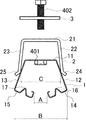
実施の形態1では、ボルト31は金具1の天板部11の下側から取り付けられている。つまり、ボルト31の頭は金具1の天板部11の下側に位置している。そして、太陽電池モジュール301を設置した後に、ナット42を締めて太陽電池モジュール301を固定金具100に固定している。本実施の形態2では、金具1の穴18に雌ねじの加工が施されている。太陽電池モジュール301を金具2の上に設置した後、上方よりボルト402で押え具3を介して太陽電池モジュール301を固定する。図7は、この発明の実施の形態2における太陽電池モジュール301の固定金具100の構成を示す側面図である。実施の形態1で説明した固定金具100の構成要素と同様の構成要素には、同一符号を付し、その説明を省略する。
In the first embodiment, the
金具1の天板部11の略中央の穴18には、雌ねじが形成されている。図7で示す金具1は、天板部11の穴18の下面にナットが固定されている。この構成に限られず、雌ねじは天板部11にバーリング加工をした後にタップ加工により形成しても良い。固定金具110は、金具1、金具2、ボルト402、ナット401および押え具3で構成されている。
A female screw is formed in the
次に太陽電池モジュール301を取り付け操作について説明する。図8は実施の形態2における太陽電池モジュール301を折板屋根60に固定した状態を示す側面図である。図8に示すように、作業者は金具1の挟持部14,15ではぜ部601の首部602を挟んで固定金具100を折板屋根60に取り付ける。はぜ部601は折板屋根60の山部603の頂点に形成されている。はぜ部601の断面は、上側が円形をしている。そして、円形の下側の首部602は細い直線状である。首部602は山部603につながっている。金具2の天板部21の上に太陽電池モジュール301を設置する。押え具3の穴32にボルト402を通す。ボルト402を金具2の穴26および金具1のナット401に通して締める。
Next, an operation for attaching the
金具2は下方に下がり、天板部21が天板部11の上側に接する。金具1の側板部12,13の最大間隔Bは金具2の側板部22,23の最大間隔Cより大きい。金具2を下げると金具1の間隔Aは狭くなる。やがて、間隔Aは折板屋根60のはぜ部61の根元の首部602の幅Wと等しくなる。その後、挟持部14,15ははぜ部601の首部602を挟み込む。間隔Aが幅Wと等しくなった以後は、屈曲部16,17が撓んで、所定の力で折板屋根60を挟持する。これで固定金具100の折板屋根60への固定が完了する。
The
図8は固定金具100が板折屋根60に固定された状態を示している。図8に示すように、金具2は金具1の内側に収まっている。挟持部14,15は水平方向に延びている。そして、挟持部14,15ははぜ部601の根元の首部602を直角に押している。
FIG. 8 shows a state in which the fixing
太陽電池モジュール301は金具2の天板部21の上に置かれる。ボルト402は、隣接する2つの太陽電池モジュール301,311の間に位置する。押え具3の略中央に空いた穴32にボルト402を通し、押え具3を取り付ける。押え具3の略中央にある穴32にボルト402を通す。図4と同様に、押え具3は隣接する太陽電池モジュール301,311のボルト402側の端部を押える。ボルト31を締めつけると、ボルト402の頭は押え具3を上方から押す。押え具3は隣接する2つの太陽電池モジュール301,311を金具2の天板21に押し当てて、この隣接する2つの太陽電池モジュール301,311を固定する。
The
実施の形態1に示す固定金具100では、太陽電池モジュール301を折板屋根60に固定する際、2個のナット41,42を締める必要があった。実施の形態2に示す固定金具110では、1本のボルト402を締めるだけで太陽電池モジュール301を折板屋根60に固定することができる。これにより、太陽電池モジュール301の折板屋根60への取り付けが容易となる。
In the fixing metal fitting 100 shown in
実施の形態3.
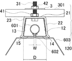
実施の形態1および実施の形態2では、金具1の挟持部14,15は挟持力を発揮させるための略V字形状の屈曲部16,17を有していた。本実施の形態3では、金具1は金具2の側板部22,23の撓みによって、挟持力を発揮する。図9は、この発明の実施の形態3における太陽電池モジュール301の固定金具120の構成を示す側面図である。図10は実施の形態3における太陽電池モジュール301を折板屋根60に固定した状態を示す側面図である。実施の形態1で説明した固定金具100の構成要素と同様の構成要素には、同一符号を付し、その説明を省略する。
In
図10に示すように、固定金具120は、金具1、金具2、ボルト31、ナット41、押え具3およびナット42で構成されている。作業者は金具1の挟持部14,15ではぜ部601の首部602を挟んで固定金具100を折板屋根60に取り付ける。はぜ部601は折板屋根60の山部603の頂点に形成されている。次にボルト31に第1のナット41を締めつける。金具2は下方に下がり、天板部21が天板部11の上側に接する。
As shown in FIG. 10, the fixing
金具1の側板部12,13の最大間隔Bは金具2の側板部22,23の最大間隔Cより大きい。金具2を下げると金具1の間隔Aは狭くなる。やがて、間隔Aは折板屋根60のはぜ部61の根元の首部602の幅Wと等しくなる。その後、挟持部14,15ははぜ部601の首部602を挟み込む。間隔Aが幅Wと等しくなった以後は、金具2の側板部22,23が撓んで、所定の力で折板屋根60の首部602を挟持する。金具2の側板部22,23が撓むことで、挟持部14,15ははぜ部601の首部602への挟持力を発生する。これで固定金具100の折板屋根60への固定が完了する。
The maximum distance B between the
図10は固定金具100が板折屋根60に固定された状態を示している。図10に示すように、金具2は金具1の内側に収まっている。挟持部14,15は水平方向に延びている。そして、挟持部14,15ははぜ部601の根元の首部602を直角に押している。側板部22,23の間隔は、太陽電池モジュール301を折板屋根60に固定する前では間隔Cである。側板部22,23の間隔は、太陽電池モジュール301を折板屋根60に固定した後では間隔Dである。側板部22,23が撓んでいるため、間隔Dの値は間隔C値よりも大きい。
FIG. 10 shows a state in which the fixing
太陽電池モジュール301は金具2の天板部21の上に置かれる。第1のナット41は、隣接する2つの太陽電池モジュール301の間に位置する。押え具3の略中央に空いた穴32にボルト31を通し、押え具3を取り付ける。押え具3の略中央にある穴32にボルト31を通す。押え具3は隣接する太陽電池モジュール301,311のボルト31側の端部を押える。第2のナット42をボルト31に締めつける。ナット42は押え具3を上方から押す。押え具3は隣接する2つの太陽電池モジュール301,311を金具2の天板21に押し当てて、この隣接する2つの太陽電池モジュール301,311を固定する。
The
実施の形態3に示す固定金具120は、金具1の形状を簡素化して、生産性を向上することができる。また、これにより固定かな部120のコストを低減することができる。
The
なお、上述の各実施の形態においては、「平行」や「垂直」などの部品間の位置関係もしくは部品の形状を示す用語を用いている場合がある。また、略正方形、略90度および略平行など「略」または「ほぼ」などの用語をつけた表現を用いている場合がある。これらは、製造上の公差や組立て上のばらつきなどを考慮した範囲を含むことを表している。このため、請求の範囲に例え「略」を記載しない場合であっても製造上の公差や組立て上のばらつきなどを考慮した範囲を含むものである。また、請求の範囲に「略」を記載した場合は製造上の公差や組立て上のばらつきなどを考慮した範囲を含むことを示している。 In each of the above-described embodiments, there are cases where terms such as “parallel” or “vertical” are used to indicate the positional relationship between components or the shape of the components. Further, there are cases where expressions with terms such as “substantially” or “substantially” such as substantially square, approximately 90 degrees, and approximately parallel are used. These represent that a range that takes into account manufacturing tolerances and assembly variations is included. For this reason, even if “abbreviation” is not described in the claims, it includes a range that takes into account manufacturing tolerances and assembly variations. In addition, when “substantially” is described in the claims, it indicates that a range in consideration of manufacturing tolerances, assembly variations, and the like is included.
1,2 金具、 11,21 天板部、 12,13,22,23 側板部、 14,15 挟持部、 16,17 屈曲部、 18,26,32 穴、 24,25 屈曲端、 3 押え具、 31,402 ボルト、 33 補助具、41,42,401 ナット、 60 折板屋根、 601 はぜ部、 602 首部 603 山部、 100,101,110,120 固定金具、 301,302,311,312 太陽電池モジュール、 A,B,C 間隔、 W 幅。 1, 2, metal fittings, 11, 21 Top plate part, 12, 13, 22, 23 Side plate part, 14, 15 Clamping part, 16, 17 Bent part, 18, 26, 32 hole, 24, 25 Bent end, 3 Presser , 31,402 bolt, 33 auxiliary tool, 41, 42, 401 nut, 60 folded plate roof, 601 hull, 602 neck, 603 mountain, 100, 101, 110, 120 fixing bracket, 301, 302, 311, 312 Solar cell module, A, B, C spacing, W width.
Claims (5)
第1の天板部および前記第1の天板部の両端に接続されて同一方向に延在する一対の第1の側板部を有し、前記第1の側板部の先端部に接続されて互いに間隔が狭くなる方向に延在する一対の挟持部をさらに有する第1の金具と、
第2の天板部および前記第2の天板部の両端に接続されて同一方向に延在する一対の第2の側板部を有する第2の金具と、
前記第1の天板部及び前記第2の天板部を接続する接続具と
を備え、
前記接続具にガイドされて前記第1の天板部を前記第2の天板部に近づけると、前記第2の側板部と前記第1の金具との接触位置が移動することで前記第1の天板部と前記第2の天板部との距離に応じて連続的に前記一対の挟持部の間隔が狭くなり前記一対の挟持部が前記設置部を掴み、前記第2の側板部が撓むことで前記挟持部に挟持力を発生させることを特徴とする太陽電池モジュールの取付け構造。 In the solar cell module mounting structure for mounting the solar cell module to the installation part,
A pair of first side plate portions connected to both ends of the first top plate portion and the first top plate portion and extending in the same direction, and connected to the distal end portion of the first side plate portion; A first metal fitting further having a pair of sandwiching portions extending in a direction in which the interval is narrowed;
A second bracket having a pair of second side plate portions connected to both ends of the second top plate portion and the second top plate portion and extending in the same direction;
A connection tool for connecting the first top plate and the second top plate,
When the first top plate portion is guided by the connector and brought close to the second top plate portion, the contact position between the second side plate portion and the first metal fitting is moved to move the first top plate portion. continuously the gap between the pair of holding portions is narrowed the pair of holding portions viewed掴the installation part according to the distance of the top plate portion and the second top plate portion of the second side plate portion mounting structure of a solar cell module which is characterized that you generate a clamping force to the clamping part by bends.
Priority Applications (1)
| Application Number | Priority Date | Filing Date | Title |
|---|---|---|---|
| JP2010247543A JP5862005B2 (en) | 2010-11-04 | 2010-11-04 | Solar cell module mounting structure and solar cell unit |
Applications Claiming Priority (1)
| Application Number | Priority Date | Filing Date | Title |
|---|---|---|---|
| JP2010247543A JP5862005B2 (en) | 2010-11-04 | 2010-11-04 | Solar cell module mounting structure and solar cell unit |
Publications (3)
| Publication Number | Publication Date |
|---|---|
| JP2012097508A JP2012097508A (en) | 2012-05-24 |
| JP2012097508A5 JP2012097508A5 (en) | 2013-12-12 |
| JP5862005B2 true JP5862005B2 (en) | 2016-02-16 |
Family
ID=46389724
Family Applications (1)
| Application Number | Title | Priority Date | Filing Date |
|---|---|---|---|
| JP2010247543A Expired - Fee Related JP5862005B2 (en) | 2010-11-04 | 2010-11-04 | Solar cell module mounting structure and solar cell unit |
Country Status (1)
| Country | Link |
|---|---|
| JP (1) | JP5862005B2 (en) |
Families Citing this family (10)
| Publication number | Priority date | Publication date | Assignee | Title |
|---|---|---|---|---|
| JP5919659B2 (en) * | 2011-06-27 | 2016-05-18 | 三菱電機株式会社 | Fixing bracket and solar cell unit |
| JP5130407B1 (en) * | 2012-03-05 | 2013-01-30 | 若井産業株式会社 | Mounting hardware for equipment mounted on the roof |
| JP5200176B1 (en) * | 2012-03-21 | 2013-05-15 | 柳井電機工業株式会社 | Solar cell module mounting bracket and fixture |
| JP6249445B2 (en) * | 2014-05-12 | 2017-12-20 | Jfe鋼板株式会社 | Attachment for roof installation and method of attaching installation for roof using the attachment |
| JP6280073B2 (en) * | 2015-03-17 | 2018-02-14 | 豊田鉄工株式会社 | Metal roof mounting bracket |
| JP5895083B1 (en) * | 2015-04-28 | 2016-03-30 | 株式会社オーティス | Roof mounting fixture |
| JP5895084B1 (en) * | 2015-04-28 | 2016-03-30 | 株式会社オーティス | Roof mounting fixture |
| JP6990917B2 (en) * | 2018-02-20 | 2022-01-12 | 株式会社サカタ製作所 | Mounting equipment |
| JP2021071016A (en) * | 2019-10-31 | 2021-05-06 | 出光興産株式会社 | Fixture |
| CN112610574B (en) * | 2020-12-14 | 2022-10-11 | 西安鑫垚陶瓷复合材料有限公司 | Metal reinforcing component for ceramic matrix composite material support and support assembling method |
Family Cites Families (10)
| Publication number | Priority date | Publication date | Assignee | Title |
|---|---|---|---|---|
| JPH0613299Y2 (en) * | 1988-02-29 | 1994-04-06 | 株式会社淀川製鋼所 | Metal plate thatched roof |
| JP2000234423A (en) * | 1999-02-16 | 2000-08-29 | Daido Steel Sheet Corp | Solar panel metal fixture for folded-plate roof and solar panel mounting structure for folded-plate roof |
| JP2000345662A (en) * | 1999-04-02 | 2000-12-12 | Maruichi:Kk | Reinforcement piece for folding roof |
| JP2001090274A (en) * | 1999-09-27 | 2001-04-03 | Misawa Homes Co Ltd | Mounting structure of solar-cell module |
| EP1126098A1 (en) * | 2000-02-18 | 2001-08-22 | Corus Bausysteme GmbH | Clamping device |
| JP2003096986A (en) * | 2001-09-27 | 2003-04-03 | Daiwa House Ind Co Ltd | Mounting structure of solar cell module on folded roof |
| JP4166230B2 (en) * | 2005-04-18 | 2008-10-15 | 株式会社淀川製鋼所 | Reinforcement structure of origami roof |
| JP2007023758A (en) * | 2005-06-15 | 2007-02-01 | Shigero Sasamoto | Metal fittings for attaching superstructure on roof |
| JP4796680B2 (en) * | 2008-05-30 | 2011-10-19 | ニイガタ製販株式会社 | Installation fixture for folding roof |
| JP3149726U (en) * | 2009-01-28 | 2009-04-09 | 株式会社佐野庄製作所 | Roof mounting bracket for goby |
-
2010
- 2010-11-04 JP JP2010247543A patent/JP5862005B2/en not_active Expired - Fee Related
Also Published As
| Publication number | Publication date |
|---|---|
| JP2012097508A (en) | 2012-05-24 |
Similar Documents
| Publication | Publication Date | Title |
|---|---|---|
| JP5862005B2 (en) | Solar cell module mounting structure and solar cell unit | |
| JP5218335B2 (en) | Mounting bracket for solar cell module | |
| JP4697641B2 (en) | Folding plate mounting bracket | |
| JP2014190132A (en) | Panel attachment metal fitting | |
| JP5919659B2 (en) | Fixing bracket and solar cell unit | |
| JP2000234423A (en) | Solar panel metal fixture for folded-plate roof and solar panel mounting structure for folded-plate roof | |
| JP2011236611A (en) | Method and structure for installing solar cell module | |
| JP5745357B2 (en) | Fixing bracket for solar cell module and solar cell unit | |
| JP4361600B1 (en) | Fixing bracket and fixing method of solar cell module | |
| JP2012177281A (en) | Metal fitting for equipment mounted on roof | |
| JP5218641B2 (en) | Mounting bracket on the roof | |
| JP5178131B2 (en) | Solar cell module mounting jig and mounting structure | |
| JP2016073037A (en) | Conductive clip for grounding and solar cell device using the same | |
| JPH11124969A (en) | Rooftop structure mounting bracket | |
| JP5200176B1 (en) | Solar cell module mounting bracket and fixture | |
| JP5999771B2 (en) | Attachment for roof installation and method of attaching installation for roof using the attachment | |
| JP2011106093A (en) | Fixing bracket and fixing method for solar panel | |
| JP5920884B2 (en) | Roof installation fixture | |
| JP2006188877A (en) | Roof top fitting | |
| JP5940003B2 (en) | Mounting bracket for installation on the roof | |
| JP2017207118A (en) | Frame fixing clamp | |
| JP5617786B2 (en) | Battery terminal mounting structure | |
| JP6022489B2 (en) | Mounting bracket for installation on the roof | |
| JP6220189B2 (en) | Outer plate mounting device and mounting bracket | |
| JP6287745B2 (en) | Mounting bracket for installation on the roof |
Legal Events
| Date | Code | Title | Description |
|---|---|---|---|
| A521 | Written amendment |
Free format text: JAPANESE INTERMEDIATE CODE: A523 Effective date: 20131024 |
|
| A621 | Written request for application examination |
Free format text: JAPANESE INTERMEDIATE CODE: A621 Effective date: 20131024 |
|
| RD01 | Notification of change of attorney |
Free format text: JAPANESE INTERMEDIATE CODE: A7421 Effective date: 20140326 |
|
| A977 | Report on retrieval |
Free format text: JAPANESE INTERMEDIATE CODE: A971007 Effective date: 20140710 |
|
| A131 | Notification of reasons for refusal |
Free format text: JAPANESE INTERMEDIATE CODE: A131 Effective date: 20140729 |
|
| A521 | Written amendment |
Free format text: JAPANESE INTERMEDIATE CODE: A523 Effective date: 20140904 |
|
| A131 | Notification of reasons for refusal |
Free format text: JAPANESE INTERMEDIATE CODE: A131 Effective date: 20150224 |
|
| A521 | Written amendment |
Free format text: JAPANESE INTERMEDIATE CODE: A523 Effective date: 20150417 |
|
| A131 | Notification of reasons for refusal |
Free format text: JAPANESE INTERMEDIATE CODE: A131 Effective date: 20150929 |
|
| A521 | Written amendment |
Free format text: JAPANESE INTERMEDIATE CODE: A523 Effective date: 20151008 |
|
| TRDD | Decision of grant or rejection written | ||
| A01 | Written decision to grant a patent or to grant a registration (utility model) |
Free format text: JAPANESE INTERMEDIATE CODE: A01 Effective date: 20151201 |
|
| A61 | First payment of annual fees (during grant procedure) |
Free format text: JAPANESE INTERMEDIATE CODE: A61 Effective date: 20151214 |
|
| R151 | Written notification of patent or utility model registration |
Ref document number: 5862005 Country of ref document: JP Free format text: JAPANESE INTERMEDIATE CODE: R151 |
|
| R250 | Receipt of annual fees |
Free format text: JAPANESE INTERMEDIATE CODE: R250 |
|
| R250 | Receipt of annual fees |
Free format text: JAPANESE INTERMEDIATE CODE: R250 |
|
| LAPS | Cancellation because of no payment of annual fees |