JP2012177281A - Metal fitting for equipment mounted on roof - Google Patents
Metal fitting for equipment mounted on roof Download PDFInfo
- Publication number
- JP2012177281A JP2012177281A JP2011041766A JP2011041766A JP2012177281A JP 2012177281 A JP2012177281 A JP 2012177281A JP 2011041766 A JP2011041766 A JP 2011041766A JP 2011041766 A JP2011041766 A JP 2011041766A JP 2012177281 A JP2012177281 A JP 2012177281A
- Authority
- JP
- Japan
- Prior art keywords
- plate
- bracket
- roof
- bent
- upper plate
- Prior art date
- Legal status (The legal status is an assumption and is not a legal conclusion. Google has not performed a legal analysis and makes no representation as to the accuracy of the status listed.)
- Withdrawn
Links
Images


Landscapes
- Roof Covering Using Slabs Or Stiff Sheets (AREA)
Abstract
Description
この発明は、建物の屋根上に固定した有頭状部材や、折版屋根におけるはぜ締め部を利用して、屋根上に屋根上搭載機器を取付けるために使用する取付け金具に関する。 The present invention relates to a mounting member used for mounting a device mounted on a roof on a roof by using a head-shaped member fixed on the roof of a building or a screw-fastening portion in a folded roof.
例えば、折版屋根の屋根上に、太陽電池モジュールのような機器を搭載する場合、折版屋根のはぜ締め部に対して複数の取付け金具を固定し、この取付け金具の上面に機器の架台を載置し、取付け金具の上面に突設させたボルトにナットを螺締めすることで、取付け金具と機器の架台を締結する方法が採られている。 For example, when a device such as a solar cell module is mounted on the roof of the folding plate roof, a plurality of mounting brackets are fixed to the fastening portion of the folding plate roof, and the device base is mounted on the upper surface of the mounting bracket. Is mounted, and a nut is screwed to a bolt projecting from the upper surface of the mounting bracket, thereby fastening the mounting bracket to the equipment base.
ところで、折版屋根のはぜ締め部に取付け金具を固定する場合、取付け金具に対して上部からの作業だけで固定が行えるようにするのが、作業の安全性と能率を向上させる点で好ましい。 By the way, when fixing the mounting bracket to the fastening portion of the folded roof, it is preferable in terms of improving the safety and efficiency of the operation that the mounting bracket can be fixed only by the work from above. .
従来、折版屋根のはぜ締め部に固定する取付け金具は、大きく分けて2種類に分類され、折版屋根のはぜ締め部を挟み込むために、はぜ締め部に上から被せる金具の両側面をボルト・ナットで締め付ける第1の方式(例えば特許文献1と2参照)と、はぜ締め部に上から被せる金具の機械的な形状変形を得るため天面に設けたボルトで締め付ける第2の方式(例えば特許文献3と4参照)がある。
Conventionally, the mounting brackets that are fixed to the claws of the folding roof are roughly classified into two types. Both sides of the brackets that cover the claws from above to sandwich the claws of the folding roof from above. A first method of tightening the surface with bolts and nuts (see, for example,
ところで、上記した第1の方式は、金具の両側面をボルト・ナットで締め付けると、その締め付け力が金具に直接加わり、金具の下部が閉じることではぜ締め部を挟持することになる。 By the way, in the above-described first method, when both side surfaces of the metal fitting are tightened with bolts and nuts, the tightening force is directly applied to the metal fitting, and when the lower portion of the metal fitting is closed, the claws are clamped.
しかし、ボルト・ナットで金具を締め付ける場合に、金具の側面から作業を行う必要があり、このため、締結に用いる電動工具の取り回しが煩雑になり、また、金具をはぜ締め部に固定した後、本来取り付けたい物品を金具の天板に設けたボルトに締結するという2つの作業工程が必要になり、工期が長くかかるという点で問題がある。 However, when tightening the metal fittings with bolts and nuts, it is necessary to work from the side of the metal fittings, which makes the handling of the power tool used for fastening complicated, and after fixing the metal fittings to the screw tightening part There is a problem in that it requires two work steps of fastening an article to be originally attached to a bolt provided on the top plate of the metal fitting, which requires a long construction period.
これに対して、上記した第2の方式は、はぜ締め部に上から被せるようにした金具の天板にボルトを設け、このボルトにナットを螺合させ、このナットの締め付けで金具に変形もしくは機械的な運動変形を与えることではぜ締め部を挟持するため、天板の上部からの作業となり、電動工具の取り回しが容易で作業をスムースに進めることができると共に、金具に取付けたい物品の締結作業とはぜ締め部への固定作業を同時に行うことが可能となり、工期短縮につながるという利点がある。 On the other hand, in the above-mentioned second method, a bolt is provided on the top plate of the metal fitting that covers the screw tightening portion from above, and a nut is screwed onto the bolt, and the metal is deformed by tightening the nut. Or, by giving mechanical movement deformation, the clamping part is clamped, so the work starts from the top of the top plate, and it is easy to handle the power tool, and the work can be carried out smoothly. The fastening work and the fastening work to the fastening part can be performed at the same time, and there is an advantage that the construction period is shortened.
ところで、上記特許文献3の取付け金具は、上辺板部の左右両端部から側辺板部を下方に向けて設けると共に、これら左右一対の側辺板部の下部にそれぞれ下辺板部を内側に向けて横向きに設け、これら下辺板部の第1の先端によりはぜ締め部を挟み、前記上辺板部に螺子棒を上向きに設けると共に、この螺子棒に雌螺子部材を螺着して装備品を装着するはぜ用屋根上取付け金具であって、前記上辺板部に前記側辺板部を一体に接続すると共に、前記側辺板部に前記下辺板部を一体に接続し、前記上辺板部の前記左右両側部より左右方向の中央部を次第に低く形成し、前記上辺板部の下面に下部当て板を当接すると共に、前記上辺板部の上面に上部当て板を当接し、前記螺子棒の下部を前記下部当て板に接続すると共に、この螺子棒を前記中央部に形成した上下方向の第1の貫通部及び前記上部当て板に形成した上下方向の第2の貫通部を貫挿させて、この螺子棒の第2の先端側に前記雌螺子部材を締め付けるようにした構造になっている。
By the way, the mounting bracket of
また、上記特許文献4の取付け金具は、基端板部と段差部と先端板部とで構成され、前記段差部の中央部に先端板部と基端板部とにそれぞれ延びる長穴と、この長穴から段差部に沿って一方の側面縁に至る切り溝が形成された緩い前方傾斜状の上板部と、上下方向に延びる補助用のリブが形成された急傾斜状の背板部と、先端両側に起立状の押さえ片が形成された幅狭な底板部とが一体構成されている金属製の挟持金具を2つ用いて、前記上板部を交差状に相対向させて、相手の切り溝内に一方の切り溝を差し込み、互いの先端板部が相手の基端板部の下側に配して長穴をそれぞれ一致させ、この一致させた長穴に下方からボルトを通し、これにボルト止めを介装させて座金付きナットを螺合して2つの挟持金具を一体構成した構造になっている。
In addition, the mounting bracket of
しかしながら、上記特許文献3の取付け金具は、少なくとも、上部が湾曲した挟持板、上部当て板、下部当て板、ボルト・ナットで構成されており、予め湾曲させた挟持板を、上部当て板と下部当て板で挟み込むことで湾曲を平板化させるというメカニズムで成り立っており、上部当て板と下部当て板を1セットで用いる構造では、その分部品点数が増え、製造コストが高くつくという問題がある。
However, the mounting bracket of
また、上記特許文献4の取付け金具は、2つの部品からなる挟持板に段差を設け、ボルト・ナットを用いて締め付けることで段差の隙間を無くすというメカニズムからなり立っており、2つの部品からなる挟持板の採用により、その分部品点数が増えるだけでなく構造が複雑化し、作業性が悪いと共に製造コストが高くつくという問題がある。
In addition, the mounting bracket of
そこで、この発明の課題は、上部からの作業だけで、屋根上の有頭状部材や折版屋根のはぜ締め部に対して固定することができるようにした取付け金具であって、有頭状部材やはぜ締め部に対する固定に手間がかからないと共に、部品点数を極力少なくすることで製造コストの低減が図れ、作業性の向上に寄与することができる屋根上搭載機器の取付け金具を提供することにある。 Therefore, an object of the present invention is a mounting bracket that can be fixed to a head-clamped portion of a head-shaped member on a roof or a folded-plate roof only by work from above, A mounting bracket for on-roof equipment that can reduce the manufacturing cost by reducing the number of parts as much as possible, and can contribute to the improvement of workability. There is.
上記のような課題を解決するため、この発明は、中央部に貫通孔を有し、端部寄りの部分が一面側に屈曲する折れ曲がり部となる座金具と、中央部に貫通孔を有する上板と、この上板の両端から一面側に折り曲げられて互いに向き合う一対の挟持板と、この挟持板の端部から互いに相手挟持板側に屈曲し、屋根上に固定した有頭状部材や折版屋根におけるはぜ締め部の首部を両側から挟むための挟持片を備えた挟持金具と、前記座金具とこの座金具の一面側に位置させた挟持金具を貫通孔の部分で締結するボルト、ナットからなり、前記ボルトにナットを螺合させて締結した時に、挟持金具の上板を座金具の折れ曲がり部で撓ませることにより両挟持片が接近するようになっている構成としたものである。 In order to solve the above-described problems, the present invention has a through-hole in the central portion, a seat bracket that is a bent portion in which a portion near the end portion is bent to one surface side, and a through-hole in the central portion. A plate, a pair of clamping plates that are bent from one end to the other side of the upper plate, and facing each other, and a headed member or folding member that is bent from the end of the clamping plate to the other clamping plate and fixed on the roof A clamping metal fitting provided with a clamping piece for clamping the neck of the fastening part in the plate roof from both sides, and a bolt for fastening the clamping metal fitting positioned on the one surface side of the seat metal fitting at the through hole portion, It consists of a nut, and when the nut is screwed onto the bolt and fastened, the upper plate of the holding fitting is bent at the bent portion of the seat fitting so that both holding pieces come closer. .
上記挟持金具の上板に、貫通孔を挟んで平行する配置で一面側に向けて膨出し、上板の撓み時における屈曲支点となる一対の屈曲リブを設け、一対の屈曲リブは、その間にボルトの頭部が納まることでボルトを回り止めにすることができる間隔になっているようにすることができる。この屈曲リブは、挟持金具の撓み支点となり、撓み量及び撓む箇所を制御することで、安定した挟持力を確保することができる。 A pair of bent ribs are provided on the upper plate of the clamping metal plate so as to bulge toward one side in a parallel arrangement with a through hole interposed therebetween, and serve as a bending fulcrum when the upper plate is bent. It can be made to be the space | interval which can make a volt | bolt non-rotating by accommodating the head of a volt | bolt. This bending rib becomes a bending fulcrum of the holding metal fitting, and a stable holding force can be secured by controlling the bending amount and the bending portion.
上記座金具の一面側で貫通孔の近傍位置に、上板の撓み量を規制するためのストッパーを突設した構造とすることができる。 It can be set as the structure which protruded the stopper for controlling the bending amount of an upper board in the position near the through-hole in the one surface side of the said seat metal fitting.
上記座金具と挟持金具は、それぞれ金属板を用いて形成され、挟持金具に対して座金具は挟持金具の厚さよりも大きな板厚とすることで、耐折れ曲がり強度が優れているようにし、挟持金具の撓み量を正確に制御することができることになる。 The above-mentioned seating bracket and clamping metal fitting are formed using metal plates, respectively. The thickness of the seating bracket is larger than the thickness of the clamping fixture, so that the bending strength is excellent and clamping is performed. The amount of bending of the metal fitting can be accurately controlled.
ここで、上記座金具は、一枚の帯状金属板を用い、中央に貫通孔を設けた天板の両側に下向きの傾斜板を連成してこれを一面側に屈曲する折れ曲がり部とした構造を有し、前記天板の下面に設けたストッパーは、貫通孔の周縁を下面側へ筒状に突出させるか、貫通孔の周縁から外方に向けて施した二本の切れ目間を下面側に折り曲げることにより形成されている。 Here, the above-mentioned seat fitting uses a single band-like metal plate, and has a structure in which a downward inclined plate is formed on both sides of a top plate provided with a through hole in the center, and this is bent to be bent to one side. The stopper provided on the lower surface of the top plate projects the peripheral edge of the through hole in a cylindrical shape toward the lower surface side, or between the two cuts made outward from the peripheral edge of the through hole on the lower surface side. It is formed by bending it.
上記挟持金具は、上板と一対の挟持板及び挟持片を、一枚の帯状金属板から折り曲げることによって形成され、中央部に貫通孔が設けられた前記上板は、上記座金具の全長よりも少し短い長さを有し、座金具の下に挟持金具を重ねた時、上板の両端部が両側傾斜板の下面に当接するようになっている。 The holding metal fitting is formed by bending an upper plate and a pair of holding plates and holding pieces from a single band-shaped metal plate, and the upper plate provided with a through hole in the center is formed from the entire length of the seat fitting. Has a slightly shorter length, and when the holding metal fittings are stacked under the seat metal fittings, both end portions of the upper plate come into contact with the lower surfaces of the both side inclined plates.
この上板に設けた屈曲リブは、前記貫通孔を挟んで上板の長さ方向に沿う両側に位置し、上板の途中を下面側に突出する断面U字状に折り曲げ、上板の幅方向全長にわたるように設けられている。 The bending ribs provided on the upper plate are positioned on both sides along the length direction of the upper plate with the through hole interposed therebetween, and bend the middle of the upper plate into a U-shaped cross section protruding to the lower surface side. It is provided to cover the entire length.
また、一対の挟持板は、上板の両端から下向きに下部窄まりの配置となるよう傾斜し、挟持片は挟持板の下端から相手側に向けて少し上向きになるような角度で折れ曲がっている。 In addition, the pair of sandwiching plates are inclined so as to be arranged in a lower constriction downward from both ends of the upper plate, and the sandwiching piece is bent at an angle so as to be slightly upward from the lower end of the sandwiching plate toward the other side. .
上記挟持板と挟持片には、幅方向の中央部にリブを上下方向に沿って設け、耐折れ曲がり強度を向上させるようにすることができる。 The clamping plate and the clamping piece can be provided with a rib along the vertical direction at the center in the width direction to improve the bending resistance.
上記座金具の下に挟持金具を重ねた状態で、挟持金具における上板の下面から両者の貫通孔に螺軸を挿通するボルトは、頭部を上板の下面に重ねた状態で、螺軸の座金具上面に突出する部分の根元にねじ山を利用して止め環やパッキンを取付け、ボルトを落下しないようにすれば、前記座金具と挟持金具の上下に重ねた組合わせ状態を保持することができ、ボルトに対してナットを予め仮り締めしておく必要がなく、取付け金具を折版屋根のハゼ部に取付けて架台を固定する場合に、一旦ナットを緩めて取り外さなければならないという作業を省くことができる。 The bolt that inserts the screw shaft from the lower surface of the upper plate to the through hole of both of the holding metal fittings with the holding metal fitting under the seat fitting is screwed with the head on the lower surface of the upper plate. If a retaining ring or packing is attached to the base of the part that protrudes from the top of the seat bracket using a screw thread, and the bolt is not dropped, the combined state of the seat bracket and the holding bracket stacked on top and bottom is maintained. It is not necessary to pre-tighten the nut to the bolt in advance, and when the mounting bracket is attached to the goby of the engraved roof and the frame is fixed, the nut must be loosened and removed once Can be omitted.
この発明によると、上下に重ねた座金具と挟持金具を結合するボルト、ナットを締め付けると、挟持金具の上板が座金具の折れ曲がり部に沿って曲がることで、両側の挟持板が内側に閉じて挟持片で屋根上に固定した有頭状部材や折版屋根のはぜ締め部の首部を両側から挟むようにしたので、上部からナットを締め付ける作業だけで有頭状部材や折版屋根のはぜ締め部に対して固定することができ、有頭状部材やはぜ締め部に対する固定に手間がかからないと共に、座金具と挟持金具及びボルト、ナットの組み合わせによって構成部品数を極力少なくし、製造コストの低減を図ることができる。 According to this invention, when the bolts and nuts that join the top and bottom seat brackets and the clamping brackets are tightened, the upper plate of the clamping brackets bend along the bent portions of the seat brackets, so that the clamping plates on both sides are closed inside. Since the neck of the head-clamped part or the folding roof of the engraved roof that is fixed on the roof with a clamping piece is sandwiched from both sides, the headed member or the engraved roof can be removed only by tightening the nut from the top. It can be fixed to the bolted part, and it takes less time to fix it to the headed member and the screwed part, and the number of components is reduced as much as possible by the combination of the seat bracket, the clamping bracket, the bolt and the nut, Manufacturing costs can be reduced.
また、座金具に加わった屋根上搭載機器からの荷重は、折れ曲がり部で挟持金具の上板の端部にかかることでこの上板を撓ませる方向に作用し、このため、荷重は挟持金具の固定力の増強に働くことで固定力の低下がなく、重量のある機器の取付けにも対応することができる。 In addition, the load from the roof-mounted equipment applied to the seating bracket acts on the bending plate at the end of the upper plate of the sandwiching bracket and acts in a direction to bend the upper plate. By working to increase the fixing force, there is no decrease in the fixing force, and it is possible to handle the installation of heavy equipment.
更に、座金具とその下部に重ねた挟持金具を両者に設けた貫通孔の部分でボルト結合することにより、取付け金具の組立て状態で両者の分離発生はなく、屋根上への持ち運びに便利であると同時に、そのままの状態で直ぐに固定できるので作業の手間を省ける。 Furthermore, it is convenient to carry on the roof because there is no separation between the mounting brackets in the assembled state by bolting the brackets and the clamping brackets stacked on both sides at the through-holes provided in both. At the same time, it can be fixed immediately as it is, saving labor.
以下、この発明の実施の形態を添付図面に基づいて説明する。 Embodiments of the present invention will be described below with reference to the accompanying drawings.
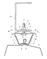
図1乃至図3に示すように、この発明の取付け金具1は、折版屋根aのはぜ締め部bに対して上から被せるようにして取付ける挟持金具2と、この挟持金具2の上に配置する座金具3と、前記座金具3と挟持金具2を結合して締め付けるボルト4及びナット5によって構成され、挟持金具2と座金具3をボルト4とナット5で締め付けることにより、座金具3の形状によって挟持金具2を内側に向けて撓ませることで、この挟持金具2が折版屋根aにおけるはぜ締め部bの首部を両側から挟むようになっている。
As shown in FIG. 1 to FIG. 3, the
上記座金具3は、図示の場合、一枚の帯状金属板を用い、中央にボルト4を挿通するための貫通孔6を設けた天板3aの長さ方向に沿う両側に、緩い角度で下面側に屈曲する屈曲部3bを連成した構造になっている。
In the case shown in the drawing, the
なお、図示省略したが、上記座金具3は、天板3aを円板状とし、その周囲に緩い傾斜の下向き屈曲部3bを全周にわたり設けて全体を円形の皿形に形成するようにしてもよい。
Although not shown in the drawings, the
上記挟持金具2は、上板7と、この上板7の両端から下部側に折り曲げられて互いに向き合う一対の挟持板8、8と、この挟持板8、8の端部から互いに相手挟持板8の側に屈曲し、折版屋根aにおけるはぜ締め部bの首部を両側から挟むための挟持片9、9を、一枚の帯状金属板から折り曲げることによって形成されている。
The clamping
上記上板7は、上記座金具3と略同様の幅とこの座金具3の全長よりも少し短い長さを有し、中央部にボルト4を挿通するための貫通孔10が設けられ、座金具3の下に挟持金具2を重ねた時、上板7の両端部が両側屈曲部3b、3bの下面に当接するようになっている。
The
上記上板7には、貫通孔10を挟んで座金具3の長さ方向に沿う両側の位置に、上板7の途中を下面側に突出する断面U字状に折り曲げた屈曲リブ11が、上板7の幅方向全長にわたるように設けられ、上板7はこの屈曲リブ11を境として中央部7aと両側の可曲部7b、7bに区画されている。
The
この上板7は、座金具3と挟持金具2を両者の貫通孔6と10に挿通したボルト4とこれに螺合したナット5で締め付けたとき、両可曲部7b、7bの端部が屈曲部3bの下面に当接して拘束されている状態で、中央部7aが座金具3に引き寄せられると、両可曲部7b、7bは屈曲リブ11を屈曲の支点として座金具3の屈曲部3bの傾斜板に沿う方向に撓むことになる。
The
従って、座金具3の形成に用いる金属板は、挟持金具2を形成する金属板よりも板厚を厚くし、耐折れ曲り強度を大きくすることで、上記した締め付けによって上板7に撓みが生じるようにしている。
Therefore, the metal plate used for forming the
上記した一対の屈曲リブ11の間隔は、貫通孔10に下から挿通したボルト4の頭部4aが上板7の下面に重なる状態でその間に丁度納まるように設定され、ボルト4を回り止め状態にすることができるようになっている。
The distance between the pair of bending
また、上記したボルト4とこれに螺合したナット5の締め付け時に、上板7を過剰に撓ませることがないよう、上記座金具3の下面で貫通孔6の周辺に、引き寄せられた上板7を停止させるためのストッパー12が設けられており、図4(a)と(b)に示す第1の例のストッパー12は、貫通孔6の周縁を下面側へ筒状に突出させることによって形成し、図4(c)乃至(e)に示す第2の例のストッパー12は、貫通孔6の周囲に二箇所の位置において、貫通孔6の周縁から外方に向けて施した二本の切れ目間を下面側に折り曲げることにより形成している。
Further, the upper plate drawn near the through
上記挟持金具2において、上板7の両端に設けた一対の挟持板8、8は、上板7の両端から下向きに折れ曲がって下部窄まりの配置となるよう内側に傾斜し、可曲部7bと挟持板8は内角が鋭角の関係となり、この挟持板8の下端に設けた挟持片9は挟持板8の下端から相手側に向けて少し上向きになるような角度で折れ曲がり、挟持金具2が自然状態にあるとき、両挟持片9、9は、この挟持片9、9の先端間を折版屋根aにおけるはぜ締め部bに対して上から押し込むことができるようにするための隙間9aが形成されるような長さになっている。
In the holding
なお、図示の場合、上記挟持板8と挟持片9には、幅方向の中央部にリブ13を上下方向に沿って設け、挟持板8と挟持片9の耐折れ曲がり強度を向上させていると共に、両挟持片9、9の先端は、金属板の延長を下面側に折り返して二重構造とし、先端部分の強度を高めるようにしている。
In the case shown in the drawing, the
上記挟持金具2の挟持板8は、上板7の可曲部7bから下方に向けて折り曲げ形成されているので、上記ボルト4とこれに螺合したナット5の締め付け時に、上板7の可曲部7bが屈曲リブ11を屈曲支点として折れ曲がると、挟持板8、8は互いに内側へ傾いて下端に設けた挟持片9、9の先端が接近し、この挟持片9、9の先端で折版屋根aにおけるはぜ締め部bの首部を両側から挟み、前記はぜ締め部bに対する取付け金具1の固定が得られることになる。
Since the
上記座金具3と挟持金具2の結合は、座金具3の下部に挟持金具2を位置させた状態で、挟持金具2と座金具3の貫通孔6と10に上板7の下面からボルト4の螺軸4bを挿通し、座金具3の上面に突出する螺軸4bに上からナット5を螺合することによって行うが、上記座金具3の下に挟持金具2を重ね、ボルト4の頭部4aを上板7の下面に重ねた状態で、座金具3の上面に突出する螺軸4bの根元部分にねじ山を利用して止め環やパッキンを取付け、ボルト4を落下しないようにすると、前記座金具3と挟持金具2の上下に重ねた組立て状態を保持することができる。
The coupling between the
このようなボルト4に対する処理により、座金具3と挟持金具2の組立て状態が保持できると共に、取付け金具1はボルト4に対してナット5を予め仮り締めしておく必要がなくなり、ナット5を別にしておくことで、取付け金具1を折版屋根aのはぜ締め部bに取付けて屋根上搭載機器の架台14に固定する場合に、一旦ナット5を緩めて取り外さなければならないという作業を省くことができ、作業能率を向上させることができるという利点がある。
By such a process for the
なお、図示の場合、取付け金具1は、折版屋根aにおけるはぜ締め部bに固定する例を示したが、例えば、起立する金属板の上端に板厚よりも広幅となる頭部を設けた断面形状のレール形有頭状部材を瓦屋根の上に固定し、取付け金具1をこのレール形有頭状部材に上記折版屋根aのはぜ締め部bと同様に固定して使用することもできる。
In the illustrated example, the mounting
また、折版屋根aの場合において、はぜ締め部bは立平ぶきの立てはぜだけでなく、蟻掛ぶきの蟻はぜであってもよい。 Further, in the case of the folded roof a, the hull tightening portion b may be not only a vertical flat stand but also an ant-splashing ant.
この発明の取付け金具1は、上記のような構成であり、次に、この取付け金具1の折版屋根aにおけるはぜ締め部bに対する取付け方法を説明する。
The mounting
図1のように、座金具3と挟持金具2を貫通孔6と10に挿通したボルト4によって上下に組み合わせた状態で、折版屋根aにおけるはぜ締め部bの直上に挟持金具2の挟持片9、9間に形成された隙間9aを臨ませ、この隙間9aをはぜ締め部bの上面に押付けるようにして取付け金具1全体を押下げると、挟持金具2の挟持片9、9がはぜ締め部bの上部によって押し開かれることで通過し、挟持金具2をはぜ締め部bに上から被せることにより、両挟持板8、8の下端が折版屋根aの上面に当接し、両挟持片9、9がはぜ締め部bの狭くなった首部の両側面に臨む仮取付け状態となり、座金具3の上面にボルト4の螺軸4bが起立している。
As shown in FIG. 1, when the
このようにして、はぜ締め部bの長さ方向の複数箇所に取付け金具1を仮取付け状態とし、屋根上搭載機器の架台14を取付け金具1上に臨ませ、この架台14に設けてあるボルト孔を螺軸4bに挿入することで、取付け金具1の座金具3の上に架台14を載置し、複数の取付け金具1で架台14を支持する。
In this way, the mounting
次に、ボルト4の螺軸4bに上からナット5を螺合して締め付けていくと、ボルト4の頭部4aとナット5で座金具3に挟持金具2の上板7が引き寄せられ、前記上板7は両側可曲部7b、7bの端部が座金具3の屈曲部3bの下面に当接して拘束されるので、引っ張り力が加わった中央部7aが座金具3に接近することになり、このため、中央部7aに対して両可曲部7b、7bが屈曲リブ11を支点として端部下がりの傾斜状に撓み、座金具3、挟持金具2、架台14の三者がボルト4とナット5で締結される。
Next, when the
上記のように、上板7の中央部7aに対して両可曲部7b、7bが端部下がりの傾斜状に撓むと、可曲部7b、7bの両端に連成した一対の挟持板8、8は、可曲部7b、7bの角度変化に一体化して互いに内側へ傾くように移動し、その下端に設けた挟持片9、9が両側から接近することで、はぜ締め部bの首部を両側から挟み込み、挟持金具2を形成する金属板の撓み力によって両挟持板8、8に挟持力が発生するので、折版屋根aのはぜ締め部bに対して取付け金具1が強固に固定化され、この取付け金具1と架台14を介して折版屋根a上に、例えば、太陽電池モジュールのような屋根上搭載機器を取付けることができる。
As described above, when the
上記した取付け金具1の固定作業において、折版屋根aのはぜ締め部bに対して挟持金具2を上から押し込むと共に、座金具3の上面に起立する螺軸4bに上からナット5を螺合するようになっているので、取付け金具1及び架台14の固定が上方からだけの作業で行えることになり、折版屋根a上での作業が行い易いという利点がある。
In the fixing operation of the mounting
また、座金具3と挟持金具2の仮組み立て状態をボルト4だけで保持しておくと、折版屋根a上での固定作業時に、予め螺軸4bに螺合したナット5を取外すような作業が不用となり、作業能率の向上が図れることになる。
Further, if the temporarily assembled state of the
更に、上記のような折版屋根aのはぜ締め部bに対する取付け金具1の固定状態において、屋根上搭載機器の重量による荷重は架台14を介して座金具3に上から作用することになるが、この座金具3と折版屋根aの上面間に位置する挟持金具2は、上板7の両可曲部7b、7bの端部が座金具3の両側屈曲部3b、3bの下面に当接した状態で端部下がりに撓み、一対の挟持板8、8は下端部が互いに接近する内向きの傾斜状態になっているので、前記した荷重は挟持金具2の両挟持板8、8に対して、下端部を互いに接近させて挟持片9、9によるはぜ締め部bの挟持力を増強させるように作用し、従って、荷重が加わることによって折版屋根aのはぜ締め部bに対する固定力が増大し、重量の大きな屋根上搭載機器の取付けが可能になる。
Furthermore, in the state where the mounting
1 取付け金具
2 挟持金具
3 座金具
3a 天板
3b 屈曲部
4 ボルト
4a 頭部
4b 螺軸
5 ナット
6 貫通孔
7 上板
7a 中央部
7b 可曲部
8 挟持板
9 挟持片
9a 隙間
10 貫通孔
11 屈曲リブ
12 ストッパー
13 リブ
14 架台
a 折版屋根
b はぜ締め部
DESCRIPTION OF
Claims (4)
中央部に貫通孔を有する上板と、この上板の両端から一面側に折り曲げられて互いに向き合う一対の挟持板と、この挟持板の端部から互いに相手挟持板側に屈曲し、屋根上に固定した有頭状部材や折版屋根におけるはぜ締め部の首部を両側から挟むための挟持片を備えた挟持金具と、
前記座金具とこの座金具の一面側に位置させた挟持金具を貫通孔の部分で締結するボルト、ナットからなり、
前記ボルトにナットを螺合させて締結した時に、挟持金具の上板を座金具の折れ曲がり部で撓ませることにより両挟持片が接近するようになっている屋根上搭載機器の取付け金具。 A seat bracket that has a through-hole in the center and a bent portion in which a portion near the end bends to one side;
An upper plate having a through hole in the central portion, a pair of holding plates that are bent from both ends of the upper plate to face each other, and bent from the end portions of the holding plate to the other holding plate side, on the roof A clamping fitting having a clamping piece for clamping the neck portion of the fastening portion in both the fixed headed member and the folded roof from both sides;
It consists of bolts and nuts that fasten the holding metal fittings and the holding metal parts located on one side of the metal fittings at the part of the through holes,
A mounting bracket for equipment mounted on a roof, in which when a nut is screwed onto a bolt and fastened, the upper plate of the clamping bracket is bent at a bent portion of the seat bracket so that both clamping pieces are brought close to each other.
Priority Applications (1)
| Application Number | Priority Date | Filing Date | Title |
|---|---|---|---|
| JP2011041766A JP2012177281A (en) | 2011-02-28 | 2011-02-28 | Metal fitting for equipment mounted on roof |
Applications Claiming Priority (1)
| Application Number | Priority Date | Filing Date | Title |
|---|---|---|---|
| JP2011041766A JP2012177281A (en) | 2011-02-28 | 2011-02-28 | Metal fitting for equipment mounted on roof |
Publications (1)
| Publication Number | Publication Date |
|---|---|
| JP2012177281A true JP2012177281A (en) | 2012-09-13 |
Family
ID=46979286
Family Applications (1)
| Application Number | Title | Priority Date | Filing Date |
|---|---|---|---|
| JP2011041766A Withdrawn JP2012177281A (en) | 2011-02-28 | 2011-02-28 | Metal fitting for equipment mounted on roof |
Country Status (1)
| Country | Link |
|---|---|
| JP (1) | JP2012177281A (en) |
Cited By (5)
| Publication number | Priority date | Publication date | Assignee | Title |
|---|---|---|---|---|
| JP2013007237A (en) * | 2011-06-27 | 2013-01-10 | Mitsubishi Electric Corp | Fixing metal fitting and solar cell unit |
| JP2013194448A (en) * | 2012-03-21 | 2013-09-30 | Yanai Co Ltd | Solar cell module mounting metal fitting and fixture |
| JP2015059365A (en) * | 2013-09-19 | 2015-03-30 | 株式会社カネカ | On-roof installation object-mounting bracket, on-roof installation object-mounting structure, solar battery module-mounting structure, roof structure, and on-roof installation object-mounting construction method |
| JP2016079796A (en) * | 2014-10-09 | 2016-05-16 | 元旦ビューティ工業株式会社 | Mounting member, and mounting structure for outside member |
| AU2017203846B2 (en) * | 2016-06-09 | 2023-04-27 | Ampelite Australia Pty Limited | A Washer for use with a Winged Fastener |
-
2011
- 2011-02-28 JP JP2011041766A patent/JP2012177281A/en not_active Withdrawn
Cited By (5)
| Publication number | Priority date | Publication date | Assignee | Title |
|---|---|---|---|---|
| JP2013007237A (en) * | 2011-06-27 | 2013-01-10 | Mitsubishi Electric Corp | Fixing metal fitting and solar cell unit |
| JP2013194448A (en) * | 2012-03-21 | 2013-09-30 | Yanai Co Ltd | Solar cell module mounting metal fitting and fixture |
| JP2015059365A (en) * | 2013-09-19 | 2015-03-30 | 株式会社カネカ | On-roof installation object-mounting bracket, on-roof installation object-mounting structure, solar battery module-mounting structure, roof structure, and on-roof installation object-mounting construction method |
| JP2016079796A (en) * | 2014-10-09 | 2016-05-16 | 元旦ビューティ工業株式会社 | Mounting member, and mounting structure for outside member |
| AU2017203846B2 (en) * | 2016-06-09 | 2023-04-27 | Ampelite Australia Pty Limited | A Washer for use with a Winged Fastener |
Similar Documents
| Publication | Publication Date | Title |
|---|---|---|
| US20120248271A1 (en) | Panel Lock Solar Clamp | |
| JP2012177281A (en) | Metal fitting for equipment mounted on roof | |
| JP5862005B2 (en) | Solar cell module mounting structure and solar cell unit | |
| JP2011236611A (en) | Method and structure for installing solar cell module | |
| JP6295233B2 (en) | Roof mounting bracket | |
| JP3176991U (en) | Folded plate roof mounting bracket | |
| JP2017078309A (en) | Seam grip metal fittings | |
| JP5223032B2 (en) | Folding plate mounting bracket | |
| JP5130407B1 (en) | Mounting hardware for equipment mounted on the roof | |
| JP5703242B2 (en) | Roof mounting fixture | |
| JP2006188877A (en) | Roof top fitting | |
| JP6128963B2 (en) | Mounting bracket | |
| JP4361600B1 (en) | Fixing bracket and fixing method of solar cell module | |
| JP5768018B2 (en) | Roof top fixture | |
| JP5200176B1 (en) | Solar cell module mounting bracket and fixture | |
| JP6418596B2 (en) | Solar cell panel mounting bracket and solar cell panel mounting structure using the mounting bracket | |
| JP2013007237A (en) | Fixing metal fitting and solar cell unit | |
| JP6000483B1 (en) | Roof mounting bracket | |
| KR102214519B1 (en) | Solar module mounting clamp | |
| JP5912481B2 (en) | Building fixture | |
| JP2014156764A (en) | Fixture of rooftop-mounting apparatus | |
| JP5999771B2 (en) | Attachment for roof installation and method of attaching installation for roof using the attachment | |
| JP5054732B2 (en) | 庇 | |
| JP5619043B2 (en) | Roof mounting fixture | |
| JP5920884B2 (en) | Roof installation fixture |
Legal Events
| Date | Code | Title | Description |
|---|---|---|---|
| A300 | Withdrawal of application because of no request for examination |
Free format text: JAPANESE INTERMEDIATE CODE: A300 Effective date: 20140513 |