JP5861886B2 - Wall-type mixed beam structure - Google Patents
Wall-type mixed beam structure Download PDFInfo
- Publication number
- JP5861886B2 JP5861886B2 JP2012089366A JP2012089366A JP5861886B2 JP 5861886 B2 JP5861886 B2 JP 5861886B2 JP 2012089366 A JP2012089366 A JP 2012089366A JP 2012089366 A JP2012089366 A JP 2012089366A JP 5861886 B2 JP5861886 B2 JP 5861886B2
- Authority
- JP
- Japan
- Prior art keywords
- wall
- reinforced concrete
- type mixed
- floor
- building
- Prior art date
- Legal status (The legal status is an assumption and is not a legal conclusion. Google has not performed a legal analysis and makes no representation as to the accuracy of the status listed.)
- Active
Links
Images


Description
本発明は、壁式混合梁構造に関する。 The present invention relates to a wall-type mixed beam structure.
従来、建物において、架構剛性を確保しながら大スパン構造を実現するには、鉄筋コンクリート(RC)構造とする必要があり、一般的にはプレストレス構造を採用している(例えば、特許文献1参照)。
特許文献1には、柱頭間に梁用パネルが橋架され、その梁用パネル間に床パネルが仮設され、梁用パネル上および床パネル間の取り合い部上部に先組梁鉄筋やPC鋼線が配筋され、これらパネル上に現場コンクリートが打設される構成について開示されている。
Conventionally, in a building, in order to realize a large span structure while ensuring frame rigidity, it is necessary to use a reinforced concrete (RC) structure, and generally a pre-stress structure is employed (for example, see Patent Document 1). ).
In Patent Document 1, a beam panel is bridged between the column heads, and a floor panel is temporarily installed between the beam panels. A configuration is disclosed in which the concrete is placed and the in-situ concrete is placed on these panels.
しかしながら、上述した従来の大スパン構造では、以下のような問題があった。
すなわち、プレストレス構造での施工においては、手間のかかる緊張作業を伴うことになるうえ、プレストレスを導入することが可能な距離に限界があることから、大スパン構造のスパン長を十分に確保することに限界があった。通常の大スパン構造の場合、柱梁による架構形式となることが多く、柱型や梁型が設けられることから、意匠的な欠点があり、空間利用の観点において不利になるという問題があった。
However, the conventional large span structure described above has the following problems.
In other words, construction with a pre-stress structure involves laborious tension work and there is a limit to the distance where pre-stress can be introduced. There was a limit to doing it. In the case of a normal large span structure, there is often a frame form with column beams, and since there are column types and beam types, there is a design disadvantage and there is a problem that it is disadvantageous in terms of space utilization .
また、従来の大スパン構造では、建物の重量が増加するため、地震力が増大することになり、構造設計上には不利になることから、その点で改善の余地があった。 Moreover, in the conventional large span structure, since the weight of the building increases, the seismic force increases, which is disadvantageous in terms of structural design, so there is room for improvement in that respect.
本発明は、上述する問題点に鑑みてなされたもので、大スパン構造を実現することができるとともに柱型や梁型をなくすことで、空間の利用性を高めることができ、意匠価値を向上させることができる壁式混合梁構造を提供することを目的とする。
また、本発明の他の目的は、建物の軽量化を図ることで地震力を低減することができる壁式混合梁構造を提供することである。
The present invention has been made in view of the above-described problems, and can realize a large span structure and can improve the utility of the space by eliminating the column shape and the beam shape, thereby improving the design value. An object of the present invention is to provide a wall-type mixed beam structure that can be made to occur.
Another object of the present invention is to provide a wall-type mixed beam structure capable of reducing seismic force by reducing the weight of a building.
上記目的を達成するため、本発明に係る壁式混合梁構造では、鉄筋コンクリート壁と、桁行方向に間隔をもって配列される複数の梁鉄骨、及び床スラブが一体に設けられた合成梁と、を備えた壁式混合梁構造であって、合成梁の複数の梁鉄骨の一方の端部同士及び他方の端部同士を組み込んで接続するとともに、桁行方向に沿って延在するフラットプレートを構成する端部鉄筋コンクリート造部が、鉄筋コンクリート壁に接合されていることを特徴としている。 In order to achieve the above object, the wall-type mixed beam structure according to the present invention includes a reinforced concrete wall, a plurality of beam steel frames arranged at intervals in the direction of the beam, and a composite beam integrally provided with a floor slab. The ends of the mixed-beam structure with a flat plate extending in the column direction while connecting and connecting one end and the other end of the plurality of beam steel frames of the composite beam The part reinforced concrete structure part is joined to the reinforced concrete wall.
本発明では、合成梁の複数の梁鉄骨のそれぞれの一端同士(他端同士)が桁行方向に延在する端部鉄筋コンクリート造部に組み込まれた状態で一体的に設けられるとともに、端部鉄筋コンクリート造部が鉄筋コンクリート壁に接合する構造となり、さらに床部分も梁鉄骨、床スラブ、および端部鉄筋コンクリート造部が一体的に組み合わされた混合構造床となることから、架構剛性を確保しながらも梁間方向のスパン長を大きく取ることが可能となり、これら鉄筋コンクリート壁、床スラブ、および端部鉄筋コンクリート造部によって囲まれる架構によって大スパン構造(空間)を形成することができる。
また、端部鉄筋コンクリート造部がフラットプレート構造であるため、柱型や梁型のない壁式構造となり、空間の利用性や自由度を高めることができるうえ、意匠性という観点においても優れた空間を実現することができる。
In the present invention, one end of each of the plurality of beam steel frames of the composite beam (the other end) is integrally provided in a state of being incorporated in the end reinforced concrete structure extending in the direction of the beam, and the end reinforced concrete structure is provided. The part is joined to the reinforced concrete wall, and the floor part is a mixed structure floor with the beam steel frame, the floor slab, and the end reinforced concrete structure integrated together, so that the frame direction is maintained while ensuring the frame rigidity. A large span structure (space) can be formed by a frame surrounded by the reinforced concrete wall, the floor slab, and the end reinforced concrete structure.
In addition, because the end reinforced concrete structure has a flat plate structure, it has a wall-type structure without columnar or beam type, which can enhance the usability and flexibility of the space, and is excellent in terms of design. Can be realized.
また、本発明の壁式混合梁構造では、架構剛性が高められるので、合成梁の床スラブの厚さ寸法を小さくすることが可能となり、階高を大きくすることができ、形成される大スパン空間をさらに有効に利用することができる。さらに、混合構造床となり、床断面を最小にすることができるので、建物の軽量化を図ることが可能となり、地震力が低減された耐震架構とすることができる。
さらに、本発明の壁式混合梁構造では、一方向構造床となり、梁間方向に沿う断面が桁行方向で同一形状の断面となるので、梁間方向には任意の長さに設定が可能となり、架構をユニット化し、それらを組み合わせることで構築することができる。
Further, in the wall type mixed beam structure of the present invention, since the frame rigidity is increased, the thickness dimension of the floor slab of the composite beam can be reduced, the floor height can be increased, and the large span to be formed is formed. Space can be used more effectively. Furthermore, since it becomes a mixed structure floor and the floor cross section can be minimized, it is possible to reduce the weight of the building, and it is possible to provide an earthquake resistant frame with reduced seismic force.
Furthermore, in the wall type mixed beam structure of the present invention, it becomes a one-way structure floor, and the cross section along the beam direction is the same shape in the direction of the beam, so it can be set to any length in the beam direction. Can be constructed by unitizing them and combining them.
また、本発明に係る壁式混合梁構造では、端部鉄筋コンクリート造部同士の間の梁鉄骨には、下面側において梁間方向のプレストレスが導入されていてもよい。 Moreover, in the wall-type mixed beam structure according to the present invention, prestress in the inter-beam direction may be introduced into the beam steel frame between the end reinforced concrete structures on the lower surface side.
本発明の壁式混合梁構造によれば、梁間方向の中間部分が梁鉄骨と床スラブのみで構成されるので、この部分の下面側に梁間方向のプレストレスを導入することで、この中間部分に生じるたわみを適宜抑制することが可能となる。 According to the wall-type mixed beam structure of the present invention, the intermediate portion in the inter-beam direction is composed only of the beam steel frame and the floor slab. Therefore, by introducing prestress in the inter-beam direction on the lower surface side of this portion, It is possible to appropriately suppress the deflection generated.
また、本発明に係る壁式混合梁構造では、端部鉄筋コンクリート造部と鉄筋コンクリート壁との接合部には、梁間方向のプレストレスが導入されていることが好ましい。 In the wall-type mixed beam structure according to the present invention, it is preferable that pre-stress in the inter-beam direction is introduced at the joint between the end reinforced concrete structure and the reinforced concrete wall.
この場合、端部鉄筋コンクリート造部と鉄筋コンクリート壁との接合部に生じ得るひび割れを防止することができる。 In this case, the crack which may arise in the junction part of an edge part reinforced concrete structure part and a reinforced concrete wall can be prevented.
本発明の壁式混合梁構造によれば、桁行方向に配列された複数の梁鉄骨のそれぞれの一端を組み込み桁行方向に沿って延在する端部鉄筋コンクリート造部が鉄筋コンクリート壁に接合することで、架構剛性を高めることができ、大スパン構造を実現することができるとともに柱型や梁型をなくすことにより、空間の利用性を高めることができ、意匠価値を向上させることができる。
また、本発明の壁式混合梁構造によれば、混合構造床となり、床断面の最小化を図ることが可能となるので、建物の軽量化に伴って地震力を低減することができ、これにより耐震架構を実現することができる。
According to the wall-type mixed beam structure of the present invention, an end reinforced concrete structure extending along the beam direction is assembled to each end of a plurality of beam steel frames arranged in the beam direction, and joined to the reinforced concrete wall. The frame rigidity can be increased, a large span structure can be realized, and the use of space can be improved by eliminating the column shape and beam shape, and the design value can be improved.
In addition, according to the wall type mixed beam structure of the present invention, it becomes a mixed structure floor, and it is possible to minimize the floor section, so that the seismic force can be reduced as the building becomes lighter. Can realize an earthquake-resistant frame.
以下、本発明の実施の形態による壁式混合梁構造について、図面に基づいて説明する。 Hereinafter, a wall type mixed beam structure according to an embodiment of the present invention will be described with reference to the drawings.
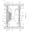
図1乃至図4に示すように、本実施の形態による壁式混合梁構造は、建物1内に大スパン空間Rを形成する構造である。
すなわち、壁式混合梁構造は、建物1の外壁を構成する鉄筋コンクリート(RC)壁2と、桁行方向Yに間隔をもって配列される複数の梁鉄骨4、及び床スラブ5が一体に設けられた合成梁3と、を備え、合成梁3の複数の梁鉄骨4の一方の端部4a同士及び他方の端部4b同士を組み込んで接続するとともに、桁行方向Yに沿って延在するフラットプレートを構成する端部鉄筋コンクリート造部(端部RC造部6)が、RC壁2に接合された構成となっている。
As shown in FIGS. 1 to 4, the wall-type mixed beam structure according to the present embodiment is a structure in which a large span space R is formed in a building 1.
That is, the wall-type mixed beam structure is a composite in which a reinforced concrete (RC)
合成梁3の梁鉄骨4は、H形鋼材からなり、図3に示すように、桁行方向Yに一定の間隔をあけて配列され、その端部4a、4bがRC壁2に接合されている。
The
端部RC造部6は、合成梁3(梁鉄骨4及び床スラブ5)の梁間方向Xの両端側に設けられる部分であり、床スラブ5に一体化され、梁鉄骨4をコンクリート中に埋設した構造をなしている。端部RC造部6の断面成(厚さ寸法)は、下面6aが大スパン空間Rの天井面から床スラブ5の床面5aまでの寸法となり、例えば600〜700mmに設定することができる。なお、このときの梁鉄骨4として、例えば高さ寸法が350mmで幅寸法が350mmのH形鋼材を採用することができる。
The
そして、RC壁2に沿って延在する端部RC造部6同士の間の部分(梁間方向Xの床中間部3a)は、合成梁3の下面側に梁鉄骨4(下フランジ部分)が露出している。なお、この床中間部3aには、端部RC造部6の下面6aと同一レベル(図2の点線)の高さ位置に天井材を設けることも可能である。
The portion between the end
ここで、端部RC造部6の梁間方向Xの長さ寸法L(図2、図3参照)は、梁間方向XでRC壁2、2の離間寸法(内法スパン)の約1/5〜1/4の長さに設定される。例えば、内法スパンが20mである場合には、上記端部RC造部6の長さ寸法Lは4〜5mとなる。
Here, the length dimension L (refer to FIGS. 2 and 3) of the end
次に、上述した構成の壁式混合梁構造の作用について、詳細に説明する。
図1乃至図4に示すように、本実施の形態の壁式混合梁構造では、合成梁3の複数の梁鉄骨4のそれぞれの一端部4a同士(他端部4b同士)が桁行方向Yに延在する端部RC造部6によって一体的に設けられるとともに、端部RC造部6がRC壁2に接合する構造となり、さらに床部分も梁鉄骨4、床スラブ5、および端部RC造部6が一体的に組み合わされた混合構造床となることから、架構剛性を確保しながらも梁間方向Xのスパン長を大きく取ることが可能となり、これらRC壁2、床スラブ5、および端部RC造部6によって囲まれる架構によって大スパン空間R(大スパン構造)を形成することができる。
Next, the operation of the wall-type mixed beam structure configured as described above will be described in detail.
As shown in FIGS. 1 to 4, in the wall-type mixed beam structure of the present embodiment, one
また、端部RC造部6がフラットプレート構造であるため、柱型や梁型のない壁式構造となり、空間の利用性や自由度を高めることができるうえ、意匠性という観点においても優れた空間を実現することができる。
Moreover, since the
また、壁式混合梁構造では、架構剛性が高められるので、合成梁3の床スラブ5の厚さ寸法を小さくすることが可能となり、階高を大きくすることができ、形成される大スパン空間Rをさらに有効に利用することができる。さらに、混合構造床となり、床断面を最小にすることができるので、建物1の軽量化を図ることが可能となり、地震力が低減された耐震架構とすることができる。
Moreover, in the wall-type mixed beam structure, the frame rigidity is increased, so that the thickness dimension of the
さらに、壁式混合梁構造では、一方向(桁行方向Y)に長い一方向構造床となり、梁間方向Xに沿う断面が桁行方向Yで同一形状の断面となるので、梁間方向Xには任意の長さに設定が可能となり、架構をプレキャストコンクリート等でユニット化し、それらを組み合わせることで構築することができる。 Furthermore, in the wall-type mixed beam structure, a unidirectional structural floor that is long in one direction (column direction Y) is formed, and the cross section along the beam direction X is the same shape in the beam direction Y. The length can be set, and the frame can be constructed by unitizing the frame with precast concrete and combining them.
また、端部RC造部6同士の間の梁鉄骨4には、下面側において例えば下フランジに対して梁間方向Xに沿ってPC鋼材(図示省略)が設けられていて、梁間方向Xのプレストレスを導入する構成としてもよい。
この場合、梁間方向Xの中間部分が梁鉄骨4と床スラブ5のみで構成されるので、この部分の下面側に梁間方向Xに沿ってプレストレスを導入することで、この中間部分に生じるたわみを適宜抑制することが可能となる。
Further, the
In this case, since the intermediate part in the inter-beam direction X is composed only of the
さらに、端部RC造部6とRC壁2との接合部Tには、梁間方向Xに沿ってPC鋼材(図示省略)が設けられていて、梁間方向Xのプレストレスを導入する構成としてもよい。
この場合、端部RC造部6とRC壁2との接合部Tに生じ得るひび割れを防止することができる。
Further, a PC steel material (not shown) is provided along the beam-to-beam direction X at the joint T between the end
In this case, the crack which may arise in the junction part T of the edge part
また、壁式混合梁構造では、梁間方向Xで床中間部3aにおける梁鉄骨4の桁行方向Yの配置間隔を小さくすることで、端部RC造部6およびRC壁2の厚さを抑えることができ、構造設計を通常のRC造床と同様に単位幅で行うことができる。
Moreover, in the wall-type mixed beam structure, the thickness of the end
上述のように本実施の形態による壁式混合梁構造では、桁行方向Yに配列された複数の梁鉄骨4のそれぞれの一端(端部4a、4b)を組み込み桁行方向Yに沿って延在する端部RC造部6がRC壁2に接合することで、架構剛性を高めることができ、大スパン空間Rを実現することができるとともに、柱型や梁型なくすことが可能となることにより、空間の利用性を高めることができ、意匠価値を向上させることができる。
また、壁式混合梁構造によれば、混合構造床となり、床断面を最小化させることが可能となるので、建物1の軽量化に伴って地震力を低減することができ、これにより耐震架構を実現することができる。
As described above, in the wall-type mixed beam structure according to the present embodiment, one end (end
Moreover, according to the wall type mixed beam structure, it becomes a mixed structure floor and the floor cross section can be minimized, so that the seismic force can be reduced as the building 1 is reduced in weight. Can be realized.
以上、本発明による壁式混合梁構造の実施の形態について説明したが、本発明は上記の実施の形態に限定されるものではなく、その趣旨を逸脱しない範囲で適宜変更可能である。
例えば、本実施の形態では建物に適用した一例を示しているが、これに限定されることはなく、例えば地下構造に適用することも可能である。
また、梁鉄骨4の寸法、複数の梁鉄骨の配列間隔(桁行寸法)、床スラブ5の厚さ寸法、端部RC造部6の桁行方向Yの長さ寸法L、厚さ寸法などの構成は、建物1の形状、大スパン空間Rの大きさ(広さ)等の施工条件に基づいて適宜設定されるものである。
As mentioned above, although embodiment of the wall type mixed beam structure by this invention was described, this invention is not limited to said embodiment, In the range which does not deviate from the meaning, it can change suitably.
For example, although an example applied to a building is shown in this embodiment, the present invention is not limited to this, and can be applied to an underground structure, for example.
Also, the configuration of the
その他、本発明の趣旨を逸脱しない範囲で、上記した実施の形態における構成要素を周知の構成要素に置き換えることは適宜可能である。 In addition, it is possible to appropriately replace the components in the above-described embodiments with known components without departing from the spirit of the present invention.
1 建物
2 RC壁(鉄筋コンクリート壁)
3 合成梁
3a 床中間部
4 梁鉄骨
4a 一方の端部
4b 他方の端部
5 床スラブ
6 端部RC造部(端部鉄筋コンクリート造部)
R 大スパン空間
T 接合部
X 梁間方向
Y 桁行方法
1 Building 2 RC wall (Reinforced concrete wall)
3
R Large span space T Joint X Beam-to-beam direction Y Digit method
Claims (3)
該合成梁の複数の梁鉄骨の一方の端部同士及び他方の端部同士を組み込んで接続するとともに、桁行方向に沿って延在するフラットプレートを構成する端部鉄筋コンクリート造部が、前記鉄筋コンクリート壁に接合されていることを特徴とする壁式混合梁構造。 A wall-type mixed beam structure comprising a reinforced concrete wall, a plurality of beam steel frames arranged at intervals in the direction of the beam, and a composite beam integrally provided with a floor slab,
An end reinforced concrete structure that constitutes a flat plate extending along the crossing direction and connecting and connecting one end of the plurality of beam steel frames and the other end of the composite beam is the reinforced concrete wall. A wall-type mixed beam structure characterized by being bonded to the wall.
Priority Applications (1)
| Application Number | Priority Date | Filing Date | Title |
|---|---|---|---|
| JP2012089366A JP5861886B2 (en) | 2012-04-10 | 2012-04-10 | Wall-type mixed beam structure |
Applications Claiming Priority (1)
| Application Number | Priority Date | Filing Date | Title |
|---|---|---|---|
| JP2012089366A JP5861886B2 (en) | 2012-04-10 | 2012-04-10 | Wall-type mixed beam structure |
Publications (2)
| Publication Number | Publication Date |
|---|---|
| JP2013217115A JP2013217115A (en) | 2013-10-24 |
| JP5861886B2 true JP5861886B2 (en) | 2016-02-16 |
Family
ID=49589542
Family Applications (1)
| Application Number | Title | Priority Date | Filing Date |
|---|---|---|---|
| JP2012089366A Active JP5861886B2 (en) | 2012-04-10 | 2012-04-10 | Wall-type mixed beam structure |
Country Status (1)
| Country | Link |
|---|---|
| JP (1) | JP5861886B2 (en) |
Families Citing this family (1)
| Publication number | Priority date | Publication date | Assignee | Title |
|---|---|---|---|---|
| CN105625583A (en) * | 2014-10-31 | 2016-06-01 | 上海宝冶集团有限公司 | Spacing connection torsion-proof node of floor boundary beam and vertical member in high-rise frame |
Family Cites Families (2)
| Publication number | Priority date | Publication date | Assignee | Title |
|---|---|---|---|---|
| US5469684A (en) * | 1993-08-10 | 1995-11-28 | Franklin; James W. | Concrete building frame construction method |
| JP2003253801A (en) * | 2003-01-28 | 2003-09-10 | Runesu Kenkyusho:Kk | Noise insulating structure for building |
-
2012
- 2012-04-10 JP JP2012089366A patent/JP5861886B2/en active Active
Also Published As
| Publication number | Publication date |
|---|---|
| JP2013217115A (en) | 2013-10-24 |
Similar Documents
| Publication | Publication Date | Title |
|---|---|---|
| JP2013181332A (en) | Reinforcing method for building structure | |
| JP4279739B2 (en) | Seismic retrofitting methods and walls for existing buildings | |
| JP5383166B2 (en) | Corrugated steel earthquake resistant wall, corrugated steel earthquake resistant wall design method, and building | |
| JP5601882B2 (en) | Steel seismic wall and building with the same | |
| JP5491962B2 (en) | Structural wall | |
| JP6265676B2 (en) | Steel shear wall | |
| JP6245890B2 (en) | building | |
| JP5861886B2 (en) | Wall-type mixed beam structure | |
| JP4945428B2 (en) | Reinforced structure | |
| JP4285427B2 (en) | Seismic reinforcement structure for buildings | |
| JP2020143502A (en) | Bearing wall | |
| JP6384905B2 (en) | Rigid plate shear wall and frame mechanism with rigid plate shear wall | |
| JP6096659B2 (en) | Wooden frame building | |
| JP7334385B2 (en) | Unit building ceiling structure | |
| JP2013087427A (en) | Earthquake strengthening structure of building | |
| JP6948864B2 (en) | Structure | |
| JP5342886B2 (en) | Unit building | |
| JP4030576B1 (en) | Wooden shear wall | |
| JP2011006987A (en) | Unit building | |
| JP5706025B2 (en) | building | |
| JP5583383B2 (en) | Stepped beam frames and buildings | |
| JP2005171548A (en) | Reinforcing structure and reinforcing method for flat plate frame | |
| JP2024013233A (en) | building structure | |
| JP5026338B2 (en) | Reinforcement structure of unit building and unit building | |
| JP2015014149A (en) | Earthquake strengthening structure |
Legal Events
| Date | Code | Title | Description |
|---|---|---|---|
| A621 | Written request for application examination |
Free format text: JAPANESE INTERMEDIATE CODE: A621 Effective date: 20150128 |
|
| A977 | Report on retrieval |
Free format text: JAPANESE INTERMEDIATE CODE: A971007 Effective date: 20151110 |
|
| TRDD | Decision of grant or rejection written | ||
| A01 | Written decision to grant a patent or to grant a registration (utility model) |
Free format text: JAPANESE INTERMEDIATE CODE: A01 Effective date: 20151124 |
|
| A61 | First payment of annual fees (during grant procedure) |
Free format text: JAPANESE INTERMEDIATE CODE: A61 Effective date: 20151209 |
|
| R150 | Certificate of patent or registration of utility model |
Ref document number: 5861886 Country of ref document: JP Free format text: JAPANESE INTERMEDIATE CODE: R150 |