JP5861663B2 - Game machine - Google Patents
Game machine Download PDFInfo
- Publication number
- JP5861663B2 JP5861663B2 JP2013094920A JP2013094920A JP5861663B2 JP 5861663 B2 JP5861663 B2 JP 5861663B2 JP 2013094920 A JP2013094920 A JP 2013094920A JP 2013094920 A JP2013094920 A JP 2013094920A JP 5861663 B2 JP5861663 B2 JP 5861663B2
- Authority
- JP
- Japan
- Prior art keywords
- game
- opening
- game ball
- variable
- entrance
- Prior art date
- Legal status (The legal status is an assumption and is not a legal conclusion. Google has not performed a legal analysis and makes no representation as to the accuracy of the status listed.)
- Expired - Fee Related
Links
- 230000008859 change Effects 0.000 claims description 24
- 230000000694 effects Effects 0.000 description 57
- 230000007246 mechanism Effects 0.000 description 22
- 238000001514 detection method Methods 0.000 description 21
- 238000013461 design Methods 0.000 description 16
- 238000000034 method Methods 0.000 description 16
- 230000008569 process Effects 0.000 description 16
- 238000005096 rolling process Methods 0.000 description 11
- 230000004048 modification Effects 0.000 description 10
- 238000012986 modification Methods 0.000 description 10
- 230000002265 prevention Effects 0.000 description 10
- 238000009825 accumulation Methods 0.000 description 7
- 238000005034 decoration Methods 0.000 description 7
- 238000004519 manufacturing process Methods 0.000 description 7
- 238000004904 shortening Methods 0.000 description 7
- 230000002093 peripheral effect Effects 0.000 description 5
- 238000003825 pressing Methods 0.000 description 5
- 230000008901 benefit Effects 0.000 description 4
- 230000000007 visual effect Effects 0.000 description 4
- 230000001186 cumulative effect Effects 0.000 description 3
- 230000005484 gravity Effects 0.000 description 3
- 238000009826 distribution Methods 0.000 description 2
- 239000011521 glass Substances 0.000 description 2
- 230000000149 penetrating effect Effects 0.000 description 2
- 238000012545 processing Methods 0.000 description 2
- 239000000758 substrate Substances 0.000 description 2
- KNMAVSAGTYIFJF-UHFFFAOYSA-N 1-[2-[(2-hydroxy-3-phenoxypropyl)amino]ethylamino]-3-phenoxypropan-2-ol;dihydrochloride Chemical compound Cl.Cl.C=1C=CC=CC=1OCC(O)CNCCNCC(O)COC1=CC=CC=C1 KNMAVSAGTYIFJF-UHFFFAOYSA-N 0.000 description 1
- 238000013459 approach Methods 0.000 description 1
- 230000007175 bidirectional communication Effects 0.000 description 1
- 230000015572 biosynthetic process Effects 0.000 description 1
- 238000004040 coloring Methods 0.000 description 1
- 239000012141 concentrate Substances 0.000 description 1
- 238000010586 diagram Methods 0.000 description 1
- 238000010304 firing Methods 0.000 description 1
- 238000005286 illumination Methods 0.000 description 1
- 230000006872 improvement Effects 0.000 description 1
- 239000004973 liquid crystal related substance Substances 0.000 description 1
- 239000002184 metal Substances 0.000 description 1
- 230000001151 other effect Effects 0.000 description 1
- 239000011120 plywood Substances 0.000 description 1
- 238000002360 preparation method Methods 0.000 description 1
- 230000004044 response Effects 0.000 description 1
Images


Landscapes
- Pinball Game Machines (AREA)
- Engineering & Computer Science (AREA)
- Multimedia (AREA)
Description
本発明は、遊技機に関し、特に、いわゆるセブン機、羽根物、権利物又はアレンジボール等の弾球式の遊技機に対して適用することができる。 The present invention relates to a gaming machine, and in particular, can be applied to a so-called seven machine, a winged article, a right article, or a ball-type gaming machine such as an arrangement ball.
弾球式の遊技機(パチンコ機)は、通常、始動口と可変入球口(大入賞口など)と一般入球口とを備え、始動口への遊技球の入球に基づき識別情報の変動表示を所定の変動時間が経過するまで行う。そして、変動表示の結果として特定の結果が得られた場合に、可変入球口への遊技球の入球が可能となる特定遊技(大当り遊技など)を実行する。 A ball-type game machine (pachinko machine) usually has a start opening, a variable entrance (such as a big prize opening), and a general entrance, and the identification information is based on the entrance of the game ball into the start opening. The fluctuation display is performed until a predetermined fluctuation time elapses. Then, when a specific result is obtained as a result of the variable display, a specific game (such as a big hit game) that allows the game ball to enter the variable entrance is executed.
かかる遊技機として、一般入球口を可変入球口の近傍に配置したものが開示されている(特許文献1を参照、以下「従来例」という。)。この遊技機によると、特定遊技中に可変入球口だけでなく、可変入球口の近傍の一般入球口に遊技球を入球させることで、特定遊技中の獲得賞球数の上積みを狙うことが可能となる。
As such a gaming machine, one in which a general entrance is arranged in the vicinity of a variable entrance is disclosed (see
ところが、この従来例に係る遊技機では、特定遊技中に可変入球口に入球しない遊技球(零れ球)が一般入球口に単に入球し得るだけなので、獲得賞球数が上積みされる印象(お得感)を遊技者に与え難い。つまり、特定遊技中に可変入球口の周囲に到達したものの可変入球口に入球しない遊技球が、遊技球受入口の大きさが変化しない入球口(不変入球口)に入球し得るだけなので、その不変入球口(一般入球口)への入球による獲得賞球数の上積みを、遊技者に効果的に訴えることができないのが実情である。 However, in the gaming machine according to this conventional example, a game ball (zero ball) that does not enter the variable entrance during a specific game can simply enter the general entrance, so the number of winning prize balls is increased. It is difficult to give the player an impression (profit). In other words, a game ball that has reached the periphery of the variable entrance during a specific game but does not enter the variable entrance enters the entrance (invariable entrance) where the size of the game entrance does not change. Therefore, the actual situation is that it is not possible to effectively appeal to the player the accumulation of the number of winning prizes by entering the invariable entrance (general entrance).
本発明は、このような問題を解決するためになされたものであり、その目的とするところは、特定遊技の際に遊技球が入球可能となる可変入球口の周辺に一般入球口を配置した遊技機において、その一般入球口の存在価値や、その一般入球口への入球により獲得する遊技価値の上積みを遊技者に効果的に訴えることである。 The present invention has been made in order to solve such a problem, and an object of the present invention is to provide a general entrance in the vicinity of a variable entrance that allows a game ball to enter during a specific game. Is to appeal to the player the existence value of the general entrance and the accumulation of the game value acquired by entering the general entrance.
本発明の遊技機は、
遊技盤面に形成される遊技領域のうち左側領域を流下する遊技球が入球可能な始動口と、
前記始動口への遊技球の入球に基づいて識別情報の変動表示を行う表示装置と、
前記遊技領域のうち右側領域を流下する遊技球が入球可能であって、前記変動表示の結果として特定の結果が得られた場合に遊技球が入球可能となるように構成された第1可変入球口と、
前記右側領域を流下する遊技球が入球可能であって、前記始動口よりも遊技球の入球可能性が低くなるように構成された一般入球口と、
前記右側領域を流下する遊技球が入球可能であって、前記一般入球口への遊技球の入球に基づき遊技球が入球可能となるように構成されるとともに、前記第1可変入球口の横方向に並んで設けられた第2可変入球口と、
所定の動作態様で動作することで、前記第1可変入球口を遊技球が入球不能な入球不能状態から遊技球が入球可能な入球可能状態に変化させる第1作動片と、
前記第1作動片と同一の動作態様で動作することで、前記第2可変入球口を遊技球が入球不能な入球不能状態から遊技球が入球可能な入球可能状態に変化させる第2作動片と、
を備えることを特徴とする。
The gaming machine of the present invention is
A start opening into which a game ball flowing down the left side of the game area formed on the game board surface can enter;
A display device for performing a variable display of identification information based on a game ball entering the start opening;
A first configuration is such that when a game ball flowing down the right region of the game area can enter and a specific result is obtained as a result of the change display, the game ball can enter the game area. Variable entrance,
A game ball that flows down the right side region is capable of entering, and a general ball entrance that is configured such that the game ball is less likely to enter than the start port; and
The game balls flowing down the right area is a possible ball entrance, based on said input ball game balls to the general ball entrance opening game ball is configured to be ball entrance Rutotomoni, the first variable input A second variable entry opening provided side by side in the lateral direction of the entry opening ;
A first actuating piece that changes the first variable entry port from an inaccessible state in which a game ball cannot enter into an enterable state in which a game ball can enter by operating in a predetermined operation mode;
By operating in the same mode of operation as the first operating piece, the second variable entrance is changed from an inaccessible state in which a game ball cannot enter into an enterable state in which a game ball can enter. A second working piece;
It is characterized by providing.
本発明では、識別情報の変動表示の結果が特定の結果になると、第1可変入球口が入球不能状態から入球可能状態に変化するだけでなく、一般入球口への遊技球の入球に基づき第2可変入球口も入球不能状態から入球可能状態に変化し、第2可変入球口への遊技球の入球が可能となる。これにより、第1可変入球口に入球しない遊技球が単に一般入球口に入球し得るだけでなく、その一般入球口への入球に基づき第2可変入球口が入球可能状態に変化して、第2可変入球口に遊技球が入球可能となるといった遊技性を実現できる。このため、第1可変入球口周辺に配置される入球口(一般入球口、第2可変入球口)の存在価値や、その入球口への入球により獲得する遊技価値の上積み(例えば、獲得賞球数の上積み)を遊技者に効果的に訴えることができる。 In the present invention, when the result of the variation display of the identification information becomes a specific result, the first variable entrance is not only changed from the entrance disabled state to the entrance enabled state, but the game ball to the general entrance is not changed. Based on the entry, the second variable entrance also changes from the entrance impossible state to the entrance enable state, and the game ball can enter the second variable entrance. As a result, game balls that do not enter the first variable entrance can not only enter the general entrance, but also the second variable entrance can enter based on the entrance to the general entrance. By changing to a possible state, it is possible to realize a game such that a game ball can enter the second variable entrance. For this reason, the existence value of the entrances (general entrance, 2nd entrance entrance) arranged around the 1st variable entrance, and the game value acquired by entering the entrance are added. (For example, the accumulation of the number of winning prize balls) can be effectively appealed to the player.
すなわち、第1可変入球口を入球不能状態から入球可能状態に変化させることを繰り返す特定遊技中において、第2可変入球口をも入球不能状態から入球可能状態に変化させ、この第2可変入球口の状態変化を遊技者に訴える。つまり、この第2可変入球口の状態変化を遊技者に視認させ、遊技価値の上積みのチャンスが到来したことを遊技者に認識させ、遊技者の期待感を高めるという効果(視覚的効果)を得ることができる。しかも、特定遊技中に第1可変入球口を注視している遊技者にとっては、第1可変入球口の周囲に到達したものの第1可変入球口に入球できなった遊技球が第2可変入球口に入球すること(拾われたこと)を視認することによって、特定遊技中に得られる遊技価値(例えば、獲得賞球数)が上積みされたことを視覚によって認識できる。このため、遊技者はお得感を感じ易くなる。 That is, during a specific game in which the first variable entrance is repeatedly changed from the no-entry state to the enterable state, the second variable entrance is also changed from the no-entry state to the enterable state, The player is informed of a change in the state of the second variable entrance. In other words, the effect that the player can visually recognize the change in the state of the second variable entrance, and that the player recognizes that the game value has a chance to accumulate, and that the player's expectation is enhanced (visual effect) Can be obtained. In addition, for a player who is gazing at the first variable entrance during a specific game, the game ball that has reached the first variable entrance but has not entered the first variable entrance is the first. 2. By visually confirming that a player has entered (picked up) a variable entrance, it is possible to visually recognize that a game value (for example, the number of winning prize balls) obtained during a specific game has been added. For this reason, it becomes easy for a player to feel a profitable feeling.
また、本発明では、第1可変入球口、一般入球口および第2可変入球口を、遊技盤面に形成される遊技領域のうち右側領域を流下する遊技球が入球可能となるように構成するため、以下の効果を得ることもできる。仮に、一般入球口を遊技領域のうち左側領域を流下する遊技球が入球可能となるように構成し、第2可変入球口を遊技領域のうち右側領域を流下する遊技球が入球可能となるように構成したとすると、第2可変入球口が入球不能状態であるときに左側領域を流下するように遊技球を発射し、一般入球口への入球に基づき第2可変入球口が入球可能状態となった際に、右側領域を流下するように遊技球を発射することが必要となる。 Further, in the present invention, a game ball flowing down the right region among the game regions formed on the game board surface can enter the first variable entrance, the general entrance, and the second variable entrance. Therefore, the following effects can be obtained. Temporarily, the general entrance is configured such that a game ball flowing down the left side of the game area can enter, and the second variable entrance is entered by a game ball flowing down the right side of the game area. If it is configured to be possible, the game ball is launched so as to flow down the left region when the second variable entrance is in a state where entry is not possible, and the second is based on the entrance to the general entrance. When the variable entrance is ready to enter, it is necessary to fire the game ball so as to flow down the right region.
つまり、第2可変入球口が入球可能状態に変化する度に、遊技球の発射強度(遊技球の流下位置)を変更することが必要となり、その結果、遊技が煩雑となったり、発射強度(遊技球の流下位置)の変更ににより第1可変入球口への入球率が低下する可能性がある。これに対して、本発明では、第1可変入球口、一般入球口および第2可変入球口が何れも遊技領域の右側領域を流下する遊技球が入球可能となるように構成されるため、特定遊技中に第2可変入球口が入球可能となった際に遊技球の発射強度(遊技球の流下位置)を変更する必要がない。よって、本発明によると、特定遊技の実行による利益(遊技価値の獲得に関する利益)を確実に享受しつつ、獲得する遊技価値の上積みを得ることができる。
なお、遊技領域のうちの左側領域あるいは右側領域とは、遊技領域の中心から上下方向(垂直方向)に延びる中心線を基準として、その中心線より左側の領域が「左側領域」に該当し、その中心線より右側の領域が「右側領域」に該当する。
In other words, it is necessary to change the launch strength of the game ball (the flow position of the game ball) every time the second variable entrance is changed to a state where it can enter the game. There is a possibility that the entrance rate to the first variable entrance is lowered due to the change in strength (flowing position of the game ball). On the other hand, in the present invention, the first variable entrance, the general entrance, and the second variable entrance are all configured such that a game ball flowing down the right area of the game area can enter. Therefore, it is not necessary to change the launch strength of the game ball (the position where the game ball flows down) when the second variable entrance becomes possible during the specific game. Therefore, according to the present invention, it is possible to obtain the accumulation of the game value to be acquired while reliably enjoying the profit (the profit related to the acquisition of the game value) by executing the specific game.
The left side area or the right side area of the game area refers to the center line extending in the vertical direction (vertical direction) from the center of the game area, and the area to the left of the center line corresponds to the “left area”. The area on the right side of the center line corresponds to the “right area”.
また、本発明では、第1可変入球口の周辺に、一般入球口および第2可変入球口を配設しつつも、遊技者が不当に遊技価値を獲得することを防止できる。蓋し、本発明では、一般入球口を始動口よりも遊技球の入球可能性が低くなるように構成することで、第1可変入球口が入球可能状態とならないとき(通常遊技時)に一般入球口を狙って遊技球を発射するメリットが生じないようになっているため、通常遊技時に一般入球口および第2可変入球口への入球に基づく遊技価値を得ようとする行為を防止できるからである。なお、本発明と異なり、ソフト的な制御によって通常遊技時には第2可変入球口が入球可能状態とならないようにすることも考えられるが、このような構成を採用すると汎用性が低くなる。これに対して、本発明によると、一般入球口の入球可能性を始動口よりも低くすることで、通常遊技時に一般入球口に向けて遊技球を発射するメリットが生じないものとなっているので、従来タイプの遊技機の既存のソフト制御を殆ど改変することなく、ハード面だけ対応することができる。
また、本発明の場合、第1可変入球口に向かって流下する遊技球が通過する部位を避けた位置に第2可変入球口が設けられるため、遊技者は、特定遊技の実行による利益(遊技価値の獲得に関する利益)をより確実に享受しつつ、獲得する遊技価値の上積みを得ることができる。また、入球可能状態に変化した第1可変入球口の隣で第2可変入球口が入球可能状態に変化するため、遊技者に対して強いインパクトを与えることができる。
更に、本発明の場合、第1作動片および第2作動片が同一の動作態様で動作するため、遊技者が一見しただけでは、第1可変入球口および第2可変入球口の区別が付き辛くなる。このため、第1可変入球口が入球可能状態となっているときに更に第2可変入球口も入球可能状態となると、遊技者に対して強いインパクトを与えることができる。
Further, according to the present invention, it is possible to prevent the player from unfairly acquiring game value while disposing the general entrance and the second variable entrance in the vicinity of the first variable entrance. In the present invention, by configuring the general entrance to be less likely to enter the game ball than the start entrance, when the first variable entrance is not ready to enter (normal game) ), The advantage of launching a game ball aiming at the general entrance is not generated, so the game value based on the entrance to the general entrance and the second variable entrance is obtained during normal game. It is because the act which tries to be prevented. Unlike the present invention, it is conceivable to prevent the second variable entrance from entering into a state in which a game can be entered during a normal game by software control. However, when such a configuration is adopted, versatility is lowered. On the other hand, according to the present invention, there is no merit of launching a game ball toward the general entrance at the time of normal game by making the entrance possibility of the general entrance lower than the start entrance. Therefore, it is possible to deal with only the hardware side without almost modifying the existing software control of the conventional type gaming machine.
Further, in the case of the present invention, since the second variable entrance is provided at a position avoiding the portion through which the game ball flowing down toward the first variable entrance enters, the player can benefit from the execution of the specific game. It is possible to obtain an accumulation of the game value to be acquired while more surely enjoying (profit related to acquisition of the game value). Further, since the second variable entrance changes to the entrance enable state next to the first variable entrance that has changed to the entrance enabled state, a strong impact can be given to the player.
Further, in the case of the present invention, since the first operating piece and the second operating piece operate in the same operation mode, the player can distinguish the first variable entry port and the second variable entry port at first glance. It becomes difficult. For this reason, if the second variable entrance is also ready to enter when the first variable entrance is ready to enter, a strong impact can be given to the player.
なお、本明細書において、「前」および「表」は、「遊技機を基準とする前方(つまり、遊技者に近接する方向)」を示し、「後」および「裏」は、遊技機を基準とする後方(つまり、遊技者から離間する方向)」を示す。また、「左」とは、遊技者から見て「左」であることを示し、「右」とは「遊技者から見て右」であることを示す。更に、本体枠、前面枠、上皿部材、下皿部材等のように、「扉の如く、開閉可能な部材(以下、「扉型部材」という。)」において、「左」、「右」、「前」、「後」等は、これらの扉型部材が使用状態にある場合、つまり、閉鎖された状態にある場合を基準としたものである。 In this specification, “front” and “front” indicate “front with respect to the gaming machine (that is, a direction closer to the player)”, and “rear” and “back” indicate the gaming machine. The reference rear (that is, the direction away from the player) "is shown. Further, “left” indicates “left” as viewed from the player, and “right” indicates “right as viewed from the player”. Further, in “a member that can be opened and closed like a door (hereinafter referred to as a“ door type member ”)” such as a main body frame, a front frame, an upper plate member, a lower plate member, etc., “left”, “right” “Front”, “Rear” and the like are based on the case where these door-type members are in use, that is, in the closed state.
また、本明細書において、遊技盤面に設けられた各種入賞口に遊技球が入る(受け入れられる)ことを、「入賞」若しくは「入球」と表記することがある。このうち、「入賞」とは、賞球の払い出しの前提となる入賞口に遊技球が入球することを示すもので、入賞口に遊技球が入る(受け入れられる)ことを示す点では、「入球」と実質的に同義である。更に、後述する大入賞装置や第2始動入賞装置のように、入賞不能(若しくは、入賞困難)な状態と入賞可能(若しくは、入賞容易)な状態とに変化可能な入賞装置において、入賞不能(若しくは、入賞困難)な状態を第1状態と称し、入賞可能(若しくは、入賞容易)な状態を第2状態と称することがある。 Further, in this specification, a game ball entering (accepting) a variety of winning holes provided on the game board surface may be referred to as “winning” or “entering”. Of these, “winning” means that a game ball enters a winning opening, which is a premise for paying out a winning ball, and that a gaming ball enters (accepts) a winning opening. Substantially synonymous with “entering ball”. Furthermore, in a winning device that can change between a state where a winning is impossible (or difficult to win) and a state where a winning is possible (or easy to win), such as a large winning device and a second start winning device described later, Alternatively, a state where it is difficult to win a prize may be referred to as a first state, and a state where a prize is possible (or easy to win) may be referred to as a second state.
以上記述したように本発明によると、特定遊技の際に遊技球が入球可能となる可変入球口(第1可変入球口)の周辺に一般入球口を配置した遊技機において、その一般入球口の存在価値や、その一般入球口への入球により獲得する遊技価値の上積みを遊技者に効果的に訴えることができる。 As described above, according to the present invention, in a gaming machine in which a general entrance is arranged around a variable entrance (first variable entrance) that allows a game ball to enter during a specific game, It is possible to effectively appeal to the player the existence value of the general entrance and the accumulation of the game value acquired by entering the general entrance.
以下、発明を実施するための形態を示す実施例について図面に基づいて説明する。以下に示す各実施例では、本発明を「セブン機」と称する遊技機(パチンコ機)1に適用した各具体例について説明する。 DESCRIPTION OF EMBODIMENTS Hereinafter, embodiments showing modes for carrying out the invention will be described with reference to the drawings. In the following embodiments, specific examples in which the present invention is applied to a gaming machine (pachinko machine) 1 referred to as a “seven machine” will be described.
(1)機械的な構造
a.遊技機の全体構造
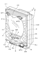
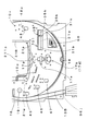
先ず、この遊技機1の全体構造について、図1を参照して説明する。この遊技機1は、外枠2と、この外枠2に装着された遊技機本体Hとを備えている。この外枠2は、略矩形状の枠状体によって構成される外枠本体2Aと、外枠本体2Aの前面下部を覆う前板部2Bとを備えている。
(1) Mechanical structure a. First, the overall structure of the
遊技機本体Hは、外枠2の左端側上下のヒンジH1、H2を用いて、外枠2の左端側に回動自在に組み付けてられている。この遊技機本体Hは、遊技機1のうち外枠2を除く部分であって、本体枠3と、前面枠4と、前面枠4に一体化された皿部材(上皿部材5および下皿部材6)5Aと、遊技盤10(図2を参照)と、裏機構盤102等を主要部としている。
The gaming machine main body H is rotatably mounted on the left end side of the
本体枠3は、外枠2に嵌めこまれ、外枠2に対して開閉可能に軸支されている。この本体枠3は、全体がプラスチック製であり、遊技盤10を保持可能な枠状体によって構成されている。この本体枠3が遊技盤10(図2を参照)を保持したとき、「遊技盤10の盤面(表面)に構成される遊技領域11」が、本体枠3の前方から視認可能とされる。
The
前面枠4は、本体枠3の前面側に配置され、本体枠3の左端に開閉可能に支持されている。この前面枠4は、前後に貫通する状態に設けられた視認窓41aを具備する枠本体41と、視認窓41aに填め込まれたガラス板43とを備えている。そして、遊技盤10に形成された遊技領域11(正面視で略円形の遊技領域11)が前面枠4を閉じたときにその背後に位置する状態とされるため、この遊技領域11は視認窓41a(ガラス板43)を介して前面枠4の前方から視認可能とされる。
The
また、本遊技機1では、「上皿部材5および下皿部材6を一体化した皿部材5A」が前面枠4に一体化され、本体枠3に対して前面枠4と一体で開閉可能とされている。但し、皿部材5Aを、本体枠3における前面枠4の装着部位よりも下方に装着し、前面枠4とは別に開閉可能としてもよい。また、上皿部材5および下皿部材6を別体に設け、本体枠3における前面枠4の装着部位よりも下方に配置し、上方に配置される上皿部材5を前面枠4とは別に開閉可能とし、下方に配置される下皿部材6を開閉不可能としてもよい。
In the
前面枠4の前面部の上方側の左右には、スピーカSP1、SP2が装着され、前板部2Bの左右両端にも、スピーカSP3、SP4が内蔵されている。そして、本遊技機1においては、これらのスピーカSP1〜SP4を用いて、遊技状態に応じた効果音や、その他の音(音声)を発生させる。また、前面枠4の前面部において、上皿部材5の配置位置を構成する箇所には、遊技機1から排出される遊技球を受け入れるための受入口5bを備えている。更に、上皿部材5の裏側には、球貸表示基板410(図16参照)および演出ボタン基板228(図16参照)が設けられ、上皿部材5の上面部には「演出ボタンSW」が配置されている。
Speakers SP1 and SP2 are mounted on the left and right sides of the front side of the
上皿部材5の下方の部位には下皿部材6が設けられ、この下皿部材6の略中央には、その略容器形状とされる内部に上皿部材5から排出される遊技球を受け入れるための受入口6aを備えている。また、下皿部材6の右端側には発射ハンドル9が設けられている。そして、本体枠3の前面部裏側(本体枠3の内部)であって、遊技盤10よりも下方の左端側に位置する部位には、発射装置ユニット90(図2を参照)が配設されており、この発射装置ユニット90に発射ハンドル9が接続されている。ここで、発射装置ユニット90は球送り装置(図示を省略)から送り出される遊技球を略鉛直上方に発射して、遊技領域11に到達させるためのものである。なお、発射ハンドル9には、遊技者が触れていることを検知するタッチスイッチ(タッチセンサ)9aが装着されており、その近傍には、遊技球の発射を一時的に停止するための発射停止スイッチ9bが装着されている。
A
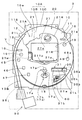
b.遊技盤10の構成
次に、遊技盤10の構成について図2を用いて説明する。この遊技盤10は正面視で略矩形状の合板を用いて構成される遊技盤本体10Aと、この遊技盤本体10Aに装着される各種の盤部品(外側レール12、内側レール13、メイン役物装置20等)が装着されている。尚、この遊技盤本体10Aの前面部には、セル画が印刷されたシート状物が貼着されているが図示を省略する。また、遊技盤10の前面部10aによって遊技盤面が構成される。
b. Next, the configuration of the
遊技盤本体10Aは、正面視で略円形とされる領域形成部10Bと、領域形成部10Bの周囲に位置する領域外部10Cとを備える。また、遊技盤本体10Aの前面部には、ともに帯状の金属板を用いて構成される外側レール12と、内側レール13とが配設されている。そして、領域形成部10Bの前面部(遊技盤面)は、この外側レール12及び内側レール13が形成する略円形の周壁によって略包囲されつつ、遊技領域11を構成している。
The game board main body 10A includes a
内側レール13は略U字形状に配置されつつ、左端部が遊技盤本体10Aは左上部に配設されるとともに、その左側方に位置する「外側レール12の左上部」との間に「遊技球が通過可能な隙間」を設け、球進入口11Sを形成している。また、外側レール12の左端部は、発射装置ユニット90の球出口96jの斜め左上に近接配置されている。また、内側レール13の外側面部には、補助レール13Bの上端部が一体化されている。そして、「補助レール13Bと、これに略平行な外側レール12の部分の間に形成される通路」と、その上方の「外側レール12と内側レール13とに挟まれつつ球進入口11Sに至る通路」とが連続して誘導経路Yを構成している。この誘導経路Yは、その下端部が「発射装置ユニット90の球出口96j」と連通するとともに、下端部から左上がり傾斜状に「内側レール13の外側(左側方)」を上昇した後、内側レール13の外側を時計回転方向に通過して球進入口11Sに到達している。
While the
領域形成部10B(遊技盤10において遊技領域11内に位置する部位)には、メイン役物装置20と、普通図柄作動ゲート(普通図柄作動口)16と、第1始動入賞装置17aと、第2始動入賞装置17bと、大入賞装置31と、可変入賞装置35と、下部表示装置60と、4個の一般入賞装置45、46、47、48と、多数の障害釘(図示を省略)と、風車19等が配設されている。
In the
メイン役物装置20は遊技領域11内の略中央部に配置されているとともに、取付部材(化粧板)21と、演出表示装置27とを備えている。このうち、取付部材21は、領域形成部10Bの前面部に装着される板状体によって構成され、図4に示すように、この取付部材(化粧板)21には正面視で略矩形状の表示窓21eが設けられている。
The
取付部材21の下縁部には、ステージ部21pが前方に突出する状態に装着され、取付部材21の周縁部のうちのその他の部位には装飾部材21Aが、前方に突出する状態に装着されている。この装飾部材21Aは、取付部材21の上縁部から突出する庇部21Hと、取付部材21の左縁部から突出する左側装飾部21Lと、取付部材21の右縁部から突出する右装飾部21Rとを備えている。
The stage member 21p is attached to the lower edge of the
左側装飾部21Lの内部に遊技球の通路(所謂「ワープ通路」)21wが形成されている。つまり、左側装飾部21Lの左側面部において、この通路21wの進入口(図示を省略)が、左斜め上方に向かって開口し、遊技領域11を流下する遊技球を、この進入口で受け入れ、ステージ部21p上(メイン役物装置20の内部)に進入させる。また、ステージ部21pは、その上面部によって遊技球の転動面を構成する。この転動面は、左右の端部から中央部に向かって下る傾斜面として構成されているが、転動面の中央部では上方に向かって僅かに隆起する隆起部とされている。
A game ball passage (a so-called “warp passage”) 21w is formed inside the left decorative portion 21L. That is, in the left side surface portion of the left decorative portion 21L, the entrance (not shown) of the passage 21w opens obliquely upward to the left, and the game ball flowing down the
本遊技機1においては、遊技領域11の左側の領域を流下し、通路21wを通じて転動面の左端部に到達した遊技球は、転動面上を右方向に転動し、更に、左方向に転動する。そして、遊技球の勢いが衰えたところで、この遊技球はメイン役物装置20外に排出されるが、転動面の中央部から排出される遊技球の多くは、一定の確率で第1始動入賞装置17aに入球する(後述する。)。つまり、転動面の左右方向に沿った中央部は後方に向かう下り傾斜を有している。また、転動面の左右方向に沿った中央部の後方には、「当該中央部の後方」から「当該中央部の下方で開口する出口211p」に至る円弧状の通過経路が設けられている(遊技盤10の側方から見て円弧状の通過経路が設けられている)。そして、転動面の左右方向に沿った中央部で勢いが衰えた遊技球は、この通過経路を通過し、出口211pを通じて遊技領域11に排出される。また、この出口211pは、第1始動入賞装置17aの鉛直上方で開口するため、出口211pから排出される遊技球が、第1始動入賞装置17aに入球する確率(可能性)が高くなっている。尚、遊技領域11を流下して第1始動入賞装置17aに入球する遊技球の中には、メイン役物装置20に進入せずに第1始動入賞装置17aに入球するものと、メイン役物装置20に進入し、ステージ部21p上を転動した後に第1始動入賞装置17aに入球するものがある。
In this
演出表示装置27は液晶表示装置を用いて構成され、下部表示装置60における特別図柄の変動表示および停止表示に合わせて図柄変動演出を実行する。なお、演出表示装置27は遊技上の表示演出を行うが、本遊技機1は「他の演出手段」として、遊技上の演出音(音声演出)を出力する音声出力手段(スピーカSP1〜SP4)と、遊技上の電飾(発光演出)を行う発光手段(ランプ装置)と、遊技上の動作演出を行う可動演出手段(可動役物装置)を備えている。
The
本実施例では、下部表示装置60(第1特別図柄表示部62a、第2特別図柄表示部62b)が、特別図柄(本図柄)を用いて変動表示(図柄変動遊技)を行い、演出表示装置27が、演出図柄(疑似図柄)を用いて変動表示(図柄変動演出)を行う。ここで、図柄変動演出は、特別図柄の変動表示の結果を遊技者に示すために、特別図柄の変動表示の進行(特別図柄の変動表示,停止表示)に合わせて行う表示演出等である。なお、以下の説明において、第1特別図柄表示部62aに表示される第1特別図柄(本図柄)と、第2特別図柄表示部62bに表示される第2特別図柄(本図柄)は何れも「識別情報」の具体例を構成する。なお、下部表示装置60(第1特別図柄表示部62a、第2特別図柄表示部62b)が「表示装置」の具体例を構成する。 In the present embodiment, the lower display device 60 (the first special symbol display unit 62a and the second special symbol display unit 62b) performs variable display (symbol variable game) using the special symbol (main symbol), and the effect display device. 27 performs variation display (design variation production) using the production design (pseudo design). Here, the symbol variation effect is a display effect or the like performed in accordance with the progress of the variation display of the special symbol (special symbol variation display, stop display) in order to show the player the result of the variation display of the special symbol. In the following description, the first special symbol (main symbol) displayed on the first special symbol display unit 62a and the second special symbol (main symbol) displayed on the second special symbol display unit 62b are both. A specific example of “identification information” is configured. The lower display device 60 (the first special symbol display unit 62a and the second special symbol display unit 62b) constitutes a specific example of the “display device”.
演出表示装置27の表示画面27aは、図3に示すように、その全体、若しくは、一部を用いて種々の図柄を遊技者が視認可能となるように表示可能である。つまり、表示画面27aの略全体が表示領域となり、この表示領域に背景を示す図柄(以下、背景図柄という。)や背景色(青、赤等の画面の地色)等を表示した状態とされる。そして、この背景図柄(背景画像)や背景色の前面に重ね合わせた状態で3つ(3桁)の演出図柄を表示する演出図柄表示領域27bが、表示画面27a上に設けられる。この演出図柄表示領域27bでは、演出図柄が横方向に3つ並んで表示され、それら「演出図柄」を用いた演出表示と停止表示等がなされる。また、背景図柄としてキャラクタを示す図柄(以下、キャラクタ図柄という。)を表示したり、実写映像(図示を省略)を表示したりすることがある。そして、これら「演出図柄」や「背景図柄」や「キャラクタ図柄」により「表示演出」が実現される。なお、演出図柄表示領域27bにおいて「演出図柄」を変動表示しているときには、演出図柄表示領域27bを透かした状態で、背景図柄や背景色が視認可能となる。
As shown in FIG. 3, the display screen 27 a of the
図3に示すように、表示画面27aのうち、左縁部寄りの上方側の位置には第1保留表示領域(D1、D2、D3、D4)が設けられ、右縁部寄りの上方側の位置には第2保留表示領域(E1、E2、E3、E4)が設けられる。そして、第1保留表示領域(D1〜D4)に、第1始動入賞装置17aへの入球に基づいて生ずる「第1特別図柄」に関する保留数(以下、「第1保留数」という。)を「4個」を上限個数として表示し、第2保留表示領域(E1〜E4)に、第2始動入賞装置17bへの入球に基づいて生ずる「第2特別図柄」に関する保留数(以下、「第2保留数」という。)を「4個」を上限個数として表示する。なお、以下の説明において、第1始動入賞装置17aに遊技球が入球することと、第2始動入賞装置17bに遊技球が入球することを「始動入賞」と称することがある。 As shown in FIG. 3, a first reserved display area (D1, D2, D3, D4) is provided at an upper position near the left edge of the display screen 27a, and an upper position near the right edge. A second hold display area (E1, E2, E3, E4) is provided at the position. In the first hold display area (D1 to D4), the number of holds (hereinafter referred to as “first hold number”) related to the “first special symbol” generated based on the ball entering the first start winning device 17a. “4” is displayed as the upper limit number, and in the second holding display area (E1 to E4), the holding number (hereinafter referred to as “the second special symbol”) generated based on the ball entering the second starting winning device 17b. "Second hold number") is displayed with "4" as the upper limit number. In the following description, a game ball entering the first start winning device 17a and a game ball entering the second start winning device 17b may be referred to as “start winning”.
何れの保留表示領域(D1〜D4、E1〜E4)も、下方から上方に向かって4個の領域(D1〜D4、E1〜E4)を並べた構成を備え、個々領域(D1〜D4、E1〜E4)に保留図柄を1個ずつ表示可能である。そして、始動入賞装置17a、17bに入球したが、未だ未消化の遊技球の数(即ち、保留数)を保留表示領域(D1〜D4、E1〜E4)に表示する保留図柄の表示数によって示す。そして、未消化の遊技球が消化される毎に、保留表示領域(D1〜D4、E1〜E4)に表示されている保留図柄の表示数を減少させることによって、「未消化の遊技球」の数(保留数)を順次、デクリメントして表示する。なお、各特別図柄に関する「未消化の遊技球(保留球)」とは、始動入賞装置17a、17bに入球したが、対応する特別図柄表示部62a、62bにおいて当該入球に伴う図柄変動表示(図柄変動遊技)がなされていない遊技球を指す。 Each hold display area (D1 to D4, E1 to E4) has a configuration in which four areas (D1 to D4 and E1 to E4) are arranged from the bottom to the top, and each area (D1 to D4 and E1). To E4), the reserved symbols can be displayed one by one. The number of game balls that have been entered into the start winning devices 17a and 17b but have not yet been digested (that is, the number of holds) are displayed in the hold display area (D1 to D4, E1 to E4). Show. And every time an undigested game ball is digested, the number of reservation symbols displayed in the hold display area (D1 to D4, E1 to E4) is reduced to reduce the number of “undigested game balls”. The number (holding number) is sequentially decremented and displayed. The “undigested game balls (holding balls)” related to each special symbol entered the start winning devices 17a and 17b, but the corresponding special symbol display units 62a and 62b display the symbol variation display accompanying the pitch. It refers to a game ball that has not been played (design variation game).
図2に示すように、第1始動入賞装置17aは非可変式の始動入賞装置であり、大きさが不変の開口部(つまり、第1始動口17p)を上方に開口させたポケット形状を備えている。この第1始動入賞装置17a(第1始動口17p)は、少なくとも遊技領域11の左側の領域を流下する遊技球が入球可能となるように設けられる。また、開口部(第1始動口17p)は、ステージ部21p(転動面)の中央部の略鉛直下方に位置するため、ワープ通路21wに進入した後、ステージ部21p(転動面)を転動し、出口211pから落下する遊技球が第1始動入賞装置17aに入球する確率(可能性)が高くなっている。また、第1始動入賞装置17aの開口部(第1始動口17p)の大きさは、1球の遊技球の通過を許容する大きさとされ、その大きさが拡大されたり縮小されたりすることはない。なお、第1始動入賞装置17aの内部には遊技球の通過を検知する第1始動口入球検知スイッチ17s(図16参照)が配設されている。
As shown in FIG. 2, the first start winning device 17a is a non-variable start winning device, and has a pocket shape in which an opening having an invariable size (that is, the first starting port 17p) is opened upward. ing. The first start winning device 17a (first start port 17p) is provided so that a game ball flowing down at least on the left side of the
第2始動入賞装置17bは可変式(開閉式)の始動入賞装置であり、第1始動入賞装置17aの直下に配設されている。この第2始動入賞装置17bは、図4(a)に示すように、遊技盤本体10Aにビス止め固定される取付板17vと、取付板17vの前面部に装着されて第2始動入賞装置17bの入口側部分を構成する普通電動役物17dと、取付板17vの前面部に装着された障害部材17Kと、を備えている。なお、前述の第1始動入賞装置17aが、この障害部材17Kとして機能してもよい。 The second start winning device 17b is a variable (open / close) start winning device, and is disposed immediately below the first start winning device 17a. As shown in FIG. 4 (a), the second start winning device 17b is attached to the mounting plate 17v fixed to the game board body 10A by screws and the front portion of the mounting plate 17v, and is attached to the second start winning device 17b. A normal electric accessory 17d that constitutes the inlet side portion and an obstruction member 17K attached to the front surface of the mounting plate 17v. The first start winning device 17a described above may function as the obstacle member 17K.
普通電動役物17dは、いわゆるチューリップ式で左右に配設された一対の可動翼片17e、17eと、一対の可動翼片17e、17eを作動させるための普通電動役物ソレノイド17c(図16参照)とを備えている。このうち、可動翼片17e、17eはそれぞれの下方側の支軸を中心に、上端側を相互に離間するように、左右に開放可能とされる。そして、両可動翼片17e、17eが立設状態となる閉鎖状態(第1状態)にあるときに、可動翼片17e、17eの上端部間の間隔が縮小される。また、普通電動役物ソレノイド17cを駆動して、両可動翼片17e、17eを、下端側の軸心に上端側を相互に離間するように傾動させると、可動翼片17e、17eの上端部間の間隔が拡大され、開放状態(第2状態)とされる。なお、第2始動入賞装置17bの可動翼片17e、17eの上端部間に形成される入賞口が「第2始動口17q」を構成する。
The ordinary electric accessory 17d is a so-called tulip-type pair of movable wing pieces 17e, 17e, and an ordinary electric
障害部材17Kは、普通電動役物17dの鉛直上方に配設されている。また、第2始動入賞装置17bの内部には遊技球の通過を検知する第2始動口入球検知スイッチ17t(図16参照)が配設されている。 The obstacle member 17K is disposed vertically above the ordinary electric accessory 17d. Further, a second start-entrance ball detection switch 17t (see FIG. 16) for detecting the passage of the game ball is disposed inside the second start winning device 17b.
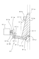
図4(a)に示すように、第2始動入賞装置17bが閉鎖状態(第1状態)になると、一対の可動翼片17e、17eの上端部間には、1球の遊技球の通過を許容する空間部(間隔)K1が形成されるが、この空間部(間隔)K1の鉛直上方に障害部材17Kが配設されている。このため、閉鎖状態(第1状態)にある第2始動入賞装置17bに遊技球が入球することは不可能されている。一方、図4(b)に示すように、第2始動入賞装置17bが開放状態(第2状態)になり、一対の可動翼片17e、17eが左右に開くと、可動翼片17e、17eの上端部間の空間部(間隔)K1(つまり、第2始動口17qの左右全幅)が、障害部材17Kの左右全幅よりも拡大される。このため、障害部材17Kの左右を通過した遊技球が、第2始動入賞装置17bへ入球することが可能となる。なお、第2始動入賞装置17b(第2始動口17q)は、少なくとも遊技領域11の左側の領域を流下する遊技球が入球可能となるように設けられる。但し、第2始動入賞装置17b(第2始動口17q)は、遊技領域11の右側の領域を流下する遊技球だけが入球可能となるように設けることもできる。
As shown in FIG. 4 (a), when the second start winning device 17b is in a closed state (first state), one game ball passes between the upper ends of the pair of movable wing pieces 17e, 17e. An allowable space (interval) K1 is formed, and an obstacle member 17K is disposed vertically above the space (interval) K1. For this reason, it is impossible for a game ball to enter the second start winning device 17b in the closed state (first state). On the other hand, as shown in FIG. 4B, when the second starting prize-winning device 17b is in an open state (second state) and the pair of movable blade pieces 17e, 17e are opened to the left and right, the movable blade pieces 17e, 17e The space (interval) K1 between the upper end portions (that is, the full left and right width of the second starting port 17q) is expanded more than the full left and right width of the obstacle member 17K. For this reason, it is possible for the game balls that have passed through the left and right of the obstacle member 17K to enter the second start winning device 17b. The second start winning device 17b (second start port 17q) is provided so that a game ball flowing down at least on the left side of the
本遊技機1においては、第2始動入賞装置17bが開放状態(第2状態)となると、遊技領域11を流下する遊技球が第2始動入賞装置17bに入球可能となる。そして、遊技機1の遊技状態が開放延長状態(後述する。)となり、第2始動入賞装置17bが開放状態となる時間が通常よりも長い時間に設定されると、遊技球が第2始動入賞装置17bに入球する確率は第1始動入賞装置17aに入球する確率に比べて遙かに高くなる。なお、本実施例では、開放延長状態における第2始動入賞装置17bの開放時間を「5秒」としており、非開放延長状態(通常開放状態)における第2始動入賞装置17bの開放時間を「0.2秒」としている。一方、前述のように、第2始動入賞装置17bが閉鎖状態(第1状態)になると、遊技球が第2始動入賞装置17bに入球することが不可能であるため、遊技機1の遊技状態が開放延長状態でない場合、遊技球が第2始動入賞装置17bに入球する確率は第1始動入賞装置17aに入球する確率に比べて遙かに低くなる。
In the
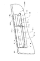
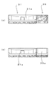
図2に示すように、メイン役物装置20の右斜め下方には大入賞装置31が配設されている。この大入賞装置31は、遊技盤10の前面部10aに装着された取付板31kを備える。この取付板31kは、図6及び7(a)に示すように、横方向に長尺に構成され、略中央部において正面形状が略帯状の開口部の表裏を貫通する状態に備え、この開口部によって大入賞口31aを構成している。そして、この大入賞口31aの後端部は「大入賞口入賞通路(図示を省略)」に連絡されている。なお、「大入賞口入賞通路」は大入賞口31aから入賞する遊技球を通過させるための通路であり、大入賞口31aに入賞した遊技球は大入賞口入賞通路を通過した後、本遊技機1の機外に排出される。なお、大入賞口31aは「第1可変入球口」の具体例を構成するものである。
As shown in FIG. 2, a
大入賞装置31は、この大入賞口31aを開放・閉鎖するための開閉部材31bと、この開閉部材31bを駆動するための大入賞口ソレノイド31c(図16参照)と、大入賞口入賞通路の経路途中若しくは経路端末部に設けられた大入賞口入球検知スイッチ31s(図16参照)とを備えている。この大入賞装置31は、開閉部材31bが起立姿勢となると、この開閉部材31bが大入賞口31aを閉鎖して閉鎖状態(第1状態)とするため、大入賞装置31への遊技球の入賞が不可能となる。なお、開閉部材31bは「第1作動片」の具体例を構成するものであり、大入賞口31aの開閉を行う開閉扉として構成されている。
The grand
開閉部材31bが起立姿勢(閉鎖状態)にあるときに、大入賞口ソレノイド31cを駆動(通電)すると、開閉部材31bはその下端部を支点に前方に傾動して前傾姿勢となる。これにより、大入賞口31aが開放状態(第2状態)とされる。また、開閉部材31bの後面部(背面部)が遊技領域11を流下し、大入賞装置31へ到達した遊技球を大入賞口31aに誘導する誘導部を構成する。また、この大入賞装置31では、大入賞口ソレノイド31cを駆動する時間(駆動時間)に応じて、大入賞口31aを開放状態に維持する時間(開放時間)が規定される。そして、大入賞口ソレノイド31cの駆動を停止(通電を停止)して、起立姿勢(閉鎖状態)に戻される。なお、開閉部材31bの左右の側縁部からは、後方に落下防止壁31dが突出している。この落下防止壁31dによって、開閉部材31bの後面部(背面部)に到達した遊技球が、開閉部材31bの左右に落下することが防止される。
When the open /
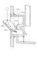
ここで、大入賞装置31を構成する開閉機構(開閉部材31bを姿勢変更するための機構)について、図8及び図9を用いて説明する。ここで、図8は、開閉部材31bが大入賞口31aを閉鎖している状態を示しており、図9は、開閉部材31bが大入賞口31aを開放している状態を示している。また、図8及び図9に示す軸31Jは、開閉部材31bの傾動軸(回動軸)を示しており、遊技盤10の盤面に沿った方向(水平な左右方向)に向けられている。
Here, the opening / closing mechanism (mechanism for changing the posture of the opening / closing
左側の落下防止壁31dの下端には、略V字の切り欠き部31eが設けられている。そして、左側の落下防止壁31dは、この切り欠き部31eの前後(開閉部材31bが立設した状態の場合の前後)で、2股に枝分かれしている。尚、以下の説明において、左側の落下防止壁31dの下端側部分のうちで、切り欠き部31eを挟んで、「前方に位置する部位」を第1の当接部31fと称し、後方に位置する部位を、第2の当接部31gと称する。
A substantially V-shaped cutout 31e is provided at the lower end of the left fall prevention wall 31d. The left fall prevention wall 31d is branched into two branches before and after the notch 31e (before and after when the opening and closing
また、開閉部材31bと大入賞口ソレノイド31cとの間には、リンク部材31Rが配設されている。なお、大入賞口ソレノイド31cは、軸受(図示を省略)によって前後にスライド可能に支持されたプランジャ31pと、プランジャ31pの外周位置に配置されたソレノイドコイル(図示を省略)と、復帰手段(復帰バネ)31qと、プランジャ31pの突端に略円板状に設けられた係止部31wとを備えている。そして、ソレノイドコイルへの通電を行わないとき、プランジャ31p及び係止部31wは復帰手段(復帰バネ)31qの付勢力により、前方に駆動し、ソレノイドコイルへの通電を行うと、ソレノイドコイルからプランジャ30pへ、電流に比例した大きさの牽引力を生ずるため、プランジャ31p及び係止部31wは復帰手段(復帰バネ)31qの付勢力に対抗しつつ後方に駆動する。
Further, a link member 31R is disposed between the opening / closing
リンク部材31Rは、中間部に設けられた回動支点部31rを中心に回動可能(揺動可能)とされている。このリンク部材31Rは、回動支点部31rの上方に略V字状に突出しつつ係止部31wを挟持する挟持部31vと、回動支点部31rの前方に突出しつつ略クランク形状に構成される押圧部31xとを備える。そして、押圧部31xの突端部31yは上方に屈曲する屈曲形状とされつつ切り欠き部31e内に遊びを持った状態で挿入されている。 The link member 31R is rotatable (swingable) about a rotation fulcrum 31r provided in the intermediate portion. The link member 31R is configured in a substantially crank shape while protruding in front of the rotation fulcrum portion 31r and a clamping portion 31v that clamps the locking portion 31w while protruding substantially V-shaped above the rotation fulcrum portion 31r. A pressing portion 31x. The projecting end portion 31y of the pressing portion 31x is inserted into the cutout portion 31e with play while being bent upward.
大入賞装置31においては、大入賞口ソレノイド31cへの通電を行わないとき、図8に示すように、プランジャ31p及び係止部31wは前方に駆動され、押圧部31xの突端部31yが、第1の当接部31fに対して後方から当接する。つまり、開閉部材31bの傾動軸(回動軸)31Jの下方に位置する「第1の当接部31f」を前方に押圧し、「起立姿勢となった開閉部材31bの後面」のうちで傾動軸(回動軸)31Jよりも上方に位置する部位が、ストッパ80vに当接するため、開閉部材31bは起立状態となる。
In the special winning
一方、大入賞装置31が閉鎖状態にあるときに、大入賞口ソレノイド31cへの通電を行うと、図9に示すように、プランジャ31p及び係止部31wは後方に駆動される。このため、係止部31wが挟持部31vを後方に引っ張るため、リンク部材31Rが回動支点部31rを中心に開放方向(遊技機1の左側方から観察して反時計方向)に回転し、押圧部31xの突端部31yが第2の当接部31gを上方に押圧する。このとき、第2の当接部31gのうちで、傾動軸(回動軸)31Jよりも後方に偏心した部位が上方に押圧されるため、開閉部材31bは、その傾動軸(回動軸)31Jを中心に前方に傾動し、前傾状態となる。
On the other hand, when the special winning opening solenoid 31c is energized when the special winning
図2に戻って更に説明すると、3個の一般入賞装置45、46、47は、メイン役物装置20の左斜め下方に配置され、1個の一般入賞装置48は、大入賞装置31の右斜め上方に配置されている。そして、各一般入賞装置45、46、47、48の内部には、遊技球の入球を検知するための一般入球検知スイッチ45s、46s、47s、48s(図16参照)が配設されている。また、3個の一般入賞装置45、46、47に入球した遊技球はそのまま機外に排出されるが、一般入賞装置48に入球した遊技球は可変入賞装置35を入球可能状態に変化させた後、機外に排出される。この点については後述する。
Returning to FIG. 2 for further explanation, the three general winning
大入賞装置31の右斜め上方に配置された一般入賞装置48は、第1始動入賞装置17aおよび第2始動入賞装置17bよりも遊技球の入球可能性が低くなるように設けられている。ここで、前述のように、第2始動入賞装置17bは可変式(開閉式)の始動入賞装置であり、第1始動入賞装置17aは非可変式の始動入賞装置であるため、第2始動入賞装置17bが開放状態(第2状態)となり、第2始動入賞装置17bの可動翼片17e、17eの上端部間に形成される入賞口(第2始動口17q)が拡大されると、第2始動入賞装置17bに遊技球が入球する可能性は、第1始動入賞装置17a(第1始動口17p)に遊技球が入球する可能性よりも高くなる。
The
また、図10に示すように、第1始動入賞装置17aは大きさが不変の開口部(第1始動口17p)を上方に開口させたポケット形状を備え、一般入賞装置48も、開口部(つまり、一般入賞口48p)を上方に開口させたポケット形状を備える。但し、第1始動口17pの周囲には、当該第1始動口17pに遊技球を誘導するための誘導釘10pが配置され、しかも、遊技球がステージ部21pを転動した後、出口211pから排出されることで、この遊技球が第1始動口17pに入球する確率(可能性)が高くなる。これに対して、一般入賞口48pの周囲には、当該一般入賞口48pに遊技球が入球する確率を低くする障害釘10rが多数配置されているため、一般入賞口48pに遊技球が入球する可能性は、第1始動口17pに遊技球が入球する可能性よりも低くなっている。なお、一般入賞口48pは「一般入球口」の具体例を構成するものである。
Further, as shown in FIG. 10, the first start winning device 17a has a pocket shape in which the opening (first starting port 17p) whose size is not changed is opened upward, and the general winning
図2に示すように、可変入賞装置35は、遊技盤10の前面部10aであって、大入賞装置31の右隣の部位に設けられている。この可変入賞装置35は、所謂「第2種非電動役物」であり、一般入賞装置48への遊技球の入球に基づき遊技球の入球が可能となるように構成されている。この可変入賞装置35は、他の入賞口(大入賞口31aを除く)に入球した遊技球の重量によって開放状態となり、可変入賞装置35自身に遊技球が入球したとき、この遊技球の重量によって閉鎖状態となる入賞装置である。以下、「可変入賞装置35」の具体例を説明するが、「可変入賞装置35」の具体的な構成は以下に示す具体例に限定されず、他の公知の構成(例えば、特開2008−104527に開示された構成等)を用いることもできる。
As shown in FIG. 2, the variable winning
この可変入賞装置35は、図6および図7に示すように、大入賞装置31を構成する取付板31kの装着部位の右隣の部位に装着された取付板35kを備える。そして、取付板35kは、図6および図7(a)に示すように、取付板31kよりも横幅が短い板状体であり、略中央部において正面形状が略帯状の開口部を、表裏を貫通する状態に備え、この開口部によって可変入賞口35aが構成されている。ここで、本実施例において、取付板35kはその左端面を取付板31kの右端面に当接させた状態に配置されているが、取付板35kおよび取付板31kを一体の板状体で構成することもできる。なお、可変入賞口35aは「第2可変入球口」の具体例を構成するものである。
As shown in FIGS. 6 and 7, the variable winning
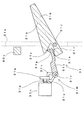
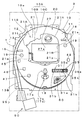
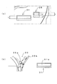
この可変入賞装置35は、図11および図12に示すように、遊技盤10の後面部に装着された基体部36と、回動軸心35Jを左右に向けつつ回動可能な状態に支持された開閉部材35bと、この開閉部材35bによる開閉動作を行うための開閉機構35cと、開閉機構35cの下方に設けられた可変入賞口入球検知スイッチ35s(図16参照)とを備えている。また、開閉部材35bは「第2作動片」の具体例を構成するものであり、前述の開閉部材31b(第1作動片)と同一の動作態様で動作する。つまり、この開閉部材35bは、可変入賞口35aの開閉を行う開閉扉として構成されている。そして、開閉部材35bが後方に回動して起立姿勢となると、この開閉部材35bが可変入賞口35aを閉鎖状態(第1状態)とするため、可変入賞装置35への遊技球の入賞が不可能となる。
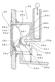
As shown in FIGS. 11 and 12, the variable
このように、開閉部材35bが起立姿勢(閉鎖状態)にあるときに、一般入賞装置48に入球した遊技球が開閉機構35cに到達すると、この遊技球の荷重が開閉機構35cに伝達される。これにより、開閉部材35bがその回動軸心35Jを基準に前方に回動(傾動)して前傾姿勢となり、可変入賞口35aが開放状態(第2状態)となる。これにより、開閉部材35bの後面部(背面部)が遊技領域11を流下して到達した遊技球を、可変入賞口35aに誘導する誘導部を構成する。そして、可変入賞口35aに入球した遊技球が、開閉機構35cに到達すると、この遊技球の荷重が開閉機構35cに伝達される。これにより、開閉部材35bの姿勢が起立姿勢(閉鎖状態)に戻され、可変入賞口35aが閉鎖される。
Thus, when the open / close member 35b is in the standing posture (closed state) and the game ball that has entered the general winning
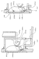
図11に示すように、基体部36は前面に開口部36aを備える略箱形状に構成され、この開口部36aを、遊技盤に設けられた貫通口10Kおよび可変入賞口35aに連通(前後に位置合わせ)させることで、可変入賞口35aに入球する遊技球が、基体部36内に進入可能されている。また、基体部36の後壁部36bの下端側には貫通口36eが設けられている。
As shown in FIG. 11, the
図12に示すように、開閉部材35bは、左右に落下防止壁35L、35Rを備え、左側の落下防止壁35Lの下端側左側面と、右側の落下防止壁35Rの下端側右側面からは、それぞれ支持突起35t、35uが突出している。また、左側の支持突起35tを、遊技盤10(貫通口10Kを形作る部位)に装着された軸受部36mで回動可能な状態に支持し、右側の支持突起35uを遊技盤10(貫通口10Kを形作る部位)に軸受部36nで回動可能(傾動可能)な状態に支持している。そして、開閉部材35bは、左右の支持突起35t、35uの軸心を通過する回動軸心35J回りに回動可能とされている。また、図11に示すように、開閉部材35bの下端側には錘体35pが埋設されているが、開閉部材35bの重心位置は、開閉部材35bの回動軸心35Jよりも上方側に位置している。但し、開閉部材35bの回動軸心35Jよりも下方側に1球の遊技球が到達すると、開閉部材35bの重心位置は、開閉部材35bの回動軸心35Jよりも下方側に移行する。
As shown in FIG. 12, the opening / closing member 35b includes left and right drop prevention walls 35L and 35R. From the lower left side of the left fall prevention wall 35L and the lower right side of the lower fall prevention wall 35R, The support protrusions 35t and 35u protrude. Further, the left support protrusion 35t is supported in a rotatable state by a bearing
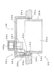
図11および図12に示すように、開閉機構35cは、第1歯車35dと、第2歯車35eと、回転規制部材35fとを備える。また、第1歯車35dおよび第2歯車35eは、何れも扇形歯車であり、回動軸心を左右に向けつつ配置されている。 As shown in FIGS. 11 and 12, the opening / closing mechanism 35c includes a first gear 35d, a second gear 35e, and a rotation restricting member 35f. Each of the first gear 35d and the second gear 35e is a sector gear, and is arranged with its rotation axis directed to the left and right.
第1歯車35dは、略円弧状に配置される歯部を後方に向けつつ、左側の落下防止壁35Lから突出する支持突起35tに対して一体回動可能な状態に装着されている。また、第2歯車35eは、略円弧状に配置される歯部を前方に向けつつ配置され、この歯部を第1歯車35dの歯部に噛合させている。更に、後壁部36bの前面部において、貫通口36eの上方に位置する部位には軸受部材36fが装着され、この軸受部材36fには軸体36gが回動可能な状態に支持されている。そして、第2歯車35eは、この軸体36gに対して一体回動可能な状態に支持されている。 The first gear 35d is mounted so as to be integrally rotatable with respect to the support protrusion 35t protruding from the left fall prevention wall 35L, with the teeth arranged in a substantially arcuate shape facing rearward. Further, the second gear 35e is disposed with the tooth portion disposed in a substantially arc shape facing forward, and the tooth portion meshes with the tooth portion of the first gear 35d. Further, a bearing member 36f is mounted on a portion of the front surface of the rear wall portion 36b above the through hole 36e, and a shaft body 36g is supported in a rotatable state on the bearing member 36f. The second gear 35e is supported so as to be capable of rotating integrally with the shaft body 36g.
図11および図12に示すように、回転規制部材35fは長尺な板状体によって構成され、一端部が軸体36gに対して一体回動可能な状態に装着され、他端部を貫通口36eに挿通させている。 As shown in FIGS. 11 and 12, the rotation restricting member 35f is formed of a long plate-like body, one end portion is mounted so as to be integrally rotatable with respect to the shaft body 36g, and the other end portion is a through-hole. 36e is inserted.
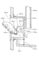
次に、開閉部材35bの姿勢が起立姿勢にあるとき(開閉部材35bが可変入賞口35aを閉鎖しているとき)を出発点として、開閉機構35cの動作態様等について説明する。まず、図11に示すように、開閉部材35bの姿勢が起立姿勢にあるときには、回転規制部材35fが、後壁部36bにおいて貫通口36eの上縁部を形作る部位(以下、第1規制部36hという。)に当接する。このとき、回転規制部材35fの他端側の部位(以下、被押圧部35gという。)が、遊技球通過樋35hの鉛直下方に位置することになる。ここで、この遊技球通過樋35hは、一般入賞装置48に入球した遊技球を可変入賞装置35に到達させるための樋である。
Next, the operation mode and the like of the opening / closing mechanism 35c will be described with the starting point when the opening / closing member 35b is in the standing posture (when the opening / closing member 35b closes the variable winning opening 35a). First, as shown in FIG. 11, when the opening / closing member 35b is in the standing posture, the rotation restricting member 35f forms the upper edge portion of the through hole 36e in the rear wall portion 36b (hereinafter referred to as the first restricting portion 36h). A). At this time, a portion on the other end side of the rotation restricting member 35f (hereinafter, referred to as a pressed portion 35g) is positioned vertically below the game ball passage rod 35h. Here, the game ball passing bar 35h is a bar for allowing the game ball that has entered the general winning
開閉部材35bの姿勢が起立姿勢にあるときに、一般入賞装置48に遊技球が入球すると、この遊技球は遊技球通過樋35hを通過した後、被押圧部35g上に落下し、この被押圧部35gを下方に押圧する。これにより、回転規制部材35fは軸体36gの軸心回りに回転(図中の矢印Rの方向に回転するが、以下、この回転方向を「第1方向」という。)する。この第1方向への回転は、被押圧部35gが後壁部36bにおいて貫通口36eの下縁部を形作る部位(以下、第2規制部36mという。)に当接すると停止する。この第1歯車35dの第1方向への回転に伴って、第2歯車35eが「第1方向」と反対の回転方向(以下、第2方向という。)に回転する。そして、第1歯車35dが第2方向に回転すると、図13に示すように、開閉部材35bも第2方向に回転し、開閉部材35bの姿勢が傾動姿勢となる。なお、遊技球通過樋35hを通過し、被押圧部35gを下方に押圧した遊技球は、本遊技機1の機外に排出される。なお、被押圧部35gを下方に押圧した遊技球は遊技球通過樋35hに進入する前に、一般入賞口入球検知スイッチ48sによって検知されているため、その時点で「遊技者への10球の賞球払出」が確定している。
When the open / close member 35b is in the standing position and a game ball enters the general winning
なお、開閉部材35bの姿勢が起立姿勢にある場合であって、被押圧部35gから第2歯車35eに回転力が加えられない場合(遊技球が被押圧部35gに落下しない場合)には、第2歯車35eが自身と噛合する第1歯車35dの回転を阻止するため、開閉部材35bの姿勢が起立姿勢に維持される。但し、図15(b)に示すように、落下防止壁35L、35Rにおいて、開閉部材35bの回動軸心35Jよりも上方であって後方に位置する部位に錘体35qを埋設すること等によって、起立姿勢にある開閉部材35bに対して、遊技盤10後方に倒れ込むような回転力を加える。そして、開閉部材35bの後面部(背面部)をストッパ35rに当接させる構成を採用することで、開閉部材35bの起立姿勢の安定化(不用意に前傾姿勢とならないようにすること)を図ることもできる。
In the case where the posture of the opening / closing member 35b is in the standing posture, and when the rotational force is not applied from the pressed portion 35g to the second gear 35e (when the game ball does not fall on the pressed portion 35g), Since the second gear 35e prevents the rotation of the first gear 35d that meshes with itself, the posture of the opening / closing member 35b is maintained in the standing posture. However, as shown in FIG. 15 (b), in the fall prevention walls 35L and 35R, by burying a weight body 35q in a portion located above and behind the rotation axis 35J of the opening / closing member 35b. Then, a rotational force that falls to the rear of the
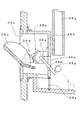
開閉部材35bの姿勢が前傾姿勢のとき(可変入賞口35aが開放状態のとき)、開閉部材35b上に遊技球が到達すると、図14に示すように、この遊技球は開閉部材35bにおいて上方に向けられた面(開閉部材35bの後面部)を転動し、可変入賞口35aに入球する。この遊技球が、開閉部材35bの回転軸心よりも下方側に到達すると、開閉部材35bの重心位置が開閉部材35bの回転軸心よりも下方側に移行するため、図15(a)に示すように、開閉部材35bは第1回転方向に回転し、起立姿勢となる。このとき、第1歯車35dも開閉部材35bと一体で第1方向に回転し、第2歯車35eおよび回転規制部材35fは第2方向に回転する。そして、開閉部材35bの姿勢が起立姿勢になると、回転規制部材35fが第1規制部36hに当接する。また、開閉部材35bが起立姿勢となることで、開閉部材35b上の遊技球は、開閉機構35cの下方に移行し、機外に排出されるが、機外に排出される前に開閉機構35cの下部に配設された可変入賞口入球検知スイッチ35sによって検知される。
When the opening / closing member 35b is tilted forward (when the variable winning opening 35a is in an open state), when the game ball reaches the opening / closing member 35b, the game ball is moved upward in the opening / closing member 35b as shown in FIG. Rolls on the surface (rear surface portion of the opening / closing member 35b) directed to, and enters the variable winning opening 35a. When the game ball reaches below the rotation axis of the opening / closing member 35b, the center of gravity of the opening / closing member 35b shifts below the rotation axis of the opening / closing member 35b. As described above, the opening / closing member 35b rotates in the first rotation direction and assumes a standing posture. At this time, the first gear 35d also rotates in the first direction integrally with the opening / closing member 35b, and the second gear 35e and the rotation restricting member 35f rotate in the second direction. When the posture of the opening / closing member 35b becomes the standing posture, the rotation restricting member 35f comes into contact with the first restricting portion 36h. Further, when the opening / closing member 35b is in the standing posture, the game ball on the opening / closing member 35b moves below the opening / closing mechanism 35c and is discharged outside the machine, but before being discharged outside the machine, the opening / closing mechanism 35c. This is detected by a variable winning opening
図2に示すように、下部表示装置60は大入賞装置31の下方に配置されている。この下部表示装置60は、図5(a)に示すように、遊技盤本体10Aの前面部に取り付けられる取付板61を備えている。そして、この取付板61には、第1特別図柄表示部62aと、第2特別図柄表示部62bと、普通図柄表示部63と、普通図柄保留表示部65等が設けられている。なお、第1特別図柄表示部62aおよび第2特別図柄表示部62bは「特別図柄表示手段」の具体例を構成する。
As shown in FIG. 2, the
図5(a)に示すように、第1特別図柄表示部62a、第2特別図柄表示部62bおよび普通図柄表示部63は、何れも「7セグメント表示体」を用いて構成されている。このうち、第1特別図柄表示部62aでは、第1始動口入球検知スイッチ17sによって遊技球が検知されることに基づいて実行される当否判定の結果を示す第1特別図柄(判定図柄)が、変動表示を経て停止表示する。また、第2特別図柄表示部62bでは、第2始動口入球検知スイッチ17tによって遊技球が検知されることに基づいて実行される当否判定の結果を示す第2特別図柄(判定図柄)が、変動表示を経て停止表示する。なお、第1特別図柄表示部62aおよび第2特別図柄表示部62bにおいて表示される変動表示(図柄変動遊技)の結果(当否判定の結果)と、演出表示装置27において表示される図柄変動演出の表示結果(当否判定の結果)は一致するものとされる。第1特別図柄表示部62aおよび第2特別図柄表示部62bの表示結果の内容については後述する。
As shown in FIG. 5A, each of the first special symbol display unit 62a, the second special symbol display unit 62b, and the normal symbol display unit 63 is configured using a “7-segment display”. Among these, in the first special symbol display section 62a, the first special symbol (determination symbol) indicating the result of the determination of success or failure executed based on the detection of the game ball by the first start-entry ball detection switch 17s. Then, stop display after changing display. In addition, in the second special symbol display unit 62b, a second special symbol (determination symbol) indicating a result of the determination as to whether or not the game ball is detected based on the detection of the game ball by the second start-entry ball detection switch 17t, Stop display after changing display. It should be noted that the result of the variation display (design variation game) displayed on the first special symbol display unit 62a and the second special symbol display unit 62b (result of determination of success / failure) and the symbol variation effect displayed on the
普通図柄表示部63は、図5(a)に示すように「7セグメント表示体」によって構成され、何れかの普通図柄作動ゲート16を遊技球が通過することに基づいて図柄変動開始条件が成立すると、普通図柄の変動表示を開始する。この普通図柄の変動表示は、普通図柄表示部63において「0」〜「9」までの算用数字をこの順で表示した後、再び、「0」〜「9」までの算用数字をこの順で表示することを繰り返す「循環表示」によって構成される。そして、普通図柄の変動表示の実行時間が経過すると、普通図柄が停止表示されて、その停止表示が一定時間実行される。このとき、停止表示された普通図柄が「奇数数字」である場合、その図柄が普通図柄の当り図柄に該当し、停止図柄が「偶数数字」である場合、その図柄が普通図柄の外れ図柄に該当する。この第2始動入賞装置17bを開放状態とすべきか否かの抽選を行う抽選手段は、後述する主制御部200Aによって構成される。
As shown in FIG. 5A, the normal symbol display unit 63 is configured by a “7-segment display body”, and the symbol variation start condition is established based on the game ball passing through one of the normal
普通図柄保留表示部65は、(a)2個のLEDを消灯させて「保留数」が「ゼロ」であることを示し、(b)1個のLEDを点灯させつつ1個のLEDを消灯させて「保留数」が「1」であることを示し、(c)2個のLEDを点灯させて「保留数」が「2」であることを示し、(d)1個のLEDを点滅させつつ1個LEDを点灯させて「保留数」が「3」であることを示し、(e)2個のLEDを点滅させて「保留数」が「4」であることを示す。 The normal symbol hold display unit 65 (a) turns off two LEDs to indicate that the “hold number” is “zero”, and (b) turns off one LED while turning on one LED. To indicate that the “hold number” is “1”, (c) turn on two LEDs to indicate that the “hold number” is “2”, and (d) blink one LED. One LED is turned on to indicate that the “holding number” is “3”, and (e) two LEDs are blinked to indicate that the “holding number” is “4”.
また、遊技盤10の下方にはアウト口18が設けられている。更に、アウト口18の下部にはバック球防止部材(図示を省略)が設けられている。そして、遊技領域11に到達せず戻ってきた遊技球が再び発射位置に戻ることを防止している。
Further, an
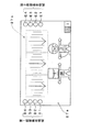
(2)制御回路の構成
次に、図16を用いて本実施例の遊技機1の制御回路の構成について説明する。本遊技機1の制御回路は、主制御部200Aと、複数の副制御部(220A、222A、240A、260A)とを含んで構成されている。つまり、主制御基板200を用いて構成されるとともに遊技の基本的な進行や賞球に関わる当否についての制御を司る主制御部200Aと、複数の副制御部(220A、222A、240A、260A)とを備えている。また、副制御部としては、(a)サブ制御基板220を用いて構成されるとともに、遊技上の演出の制御を司るサブ制御部220Aと、(b)演出表示制御基板222を用いて構成されるとともに、演出表示装置27の制御を司る演出表示制御部222Aと、(c)払出制御基板240を用いて構成されるとともに貸球や賞球を払い出す動作の制御を司る払出制御部240Aと、(d)発射制御基板260を用いて構成されるとともに遊技球の発射に関する制御を司る発射制御部260Aを備える。
(2) Configuration of Control Circuit Next, the configuration of the control circuit of the
これらの制御部(200A、220A、222A、240A、260A)を構成する制御基板(200、220、222、240、260)は、各種論理演算および算出演算を実行するCPUや、CPUで実行される各種プログラムやデータが記憶されているROM、プログラムの実行に際してCPUが一時的なデータを記憶するRAM、周辺機器とのデータのやり取りを行うための周辺機器インターフェース(PIO)、CPUが演算を行うためのクロックを出力する発振器、CPUの暴走を監視するウォッチドッグタイマなど、種々の周辺LSIがバスで相互に接続されて構成されている。尚、図16中の矢印の向きは、データあるいは信号を入出力する方向を表している。また、主制御基板200においては、搭載されたCPU201、RAM202、ROM203を図示し、サブ制御基板220においても、搭載されたCPU220a、RAM220b、ROM220cを図示し、その他の制御基板に搭載されているCPUや、RAM、ROMなどについては図示を省略している。
The control boards (200, 220, 222, 240, 260) constituting these control units (200A, 220A, 222A, 240A, 260A) are executed by a CPU that executes various logical operations and calculation operations, and the CPU. ROM in which various programs and data are stored, RAM in which the CPU stores temporary data when the program is executed, a peripheral device interface (PIO) for exchanging data with peripheral devices, and the CPU performs calculations Various peripheral LSIs such as an oscillator that outputs a clock of the above and a watchdog timer that monitors the runaway of the CPU are connected to each other via a bus. In addition, the direction of the arrow in FIG. 16 represents the direction which inputs / outputs a data or a signal. In addition, the CPU 201,
主制御部200Aは、普通図柄作動ゲート通過検知出スイッチ16s、始動口入球検知スイッチ17s、17t、一般入球検知スイッチ45s、46s、47s、48s、可変入賞口入球検知スイッチ35s等から遊技球の検知信号を受け取って、遊技の基本的な進行や賞球に関わる当否を決定した後、サブ制御部220Aや、払出制御部240A、発射制御部260A等に向かって、後述する各種の信号(コマンド)を出力する。また、主制御部200A(主制御基板200)には、発射装置ユニットから発射された遊技球を検知するカウントスイッチ8sも接続されている。また、主制御部200Aは、普通電動役物ソレノイド17cや、大入賞口ソレノイド31c、下部表示装置60に信号を出力することにより、これらの動作を直接制御している。また、主制御部200A(主制御基板200)を構成するCPU201により決定された所定の信号(コマンド)は、サブ制御基板220や払出制御基板240に対してそれぞれ送信される。
The
サブ制御部220Aは、主制御部200Aからの各種信号(コマンド)を受け取ると、信号(コマンド)の内容を解析して、その結果に応じた遊技の演出を行う。つまり、サブ制御部220Aは、主制御部200Aからの制御信号に基づいて遊技の演出の制御を司るものである。このサブ制御部220Aには、演出表示制御部222Aと、アンプ基板224と、装飾駆動基板226と、演出ボタンSW(図1を参照)が接続された演出ボタン基板228と、にそれぞれ電気的に接続されている。そして、サブ制御基板220のCPU220aは、主制御基板200からの制御信号を受けて演出表示制御基板222、アンプ基板224、装飾駆動基板226および演出ボタン基板228などの各基板を制御する。また、ROM220cには、各基板の制御に必要なデータ(特に遊技の装飾に関する情報)が記憶されている。また、CPU220aは、主制御部200Aから送出された表示制御コマンド(表示制御信号)を受信するとともに、ROM220cに記憶されたプログラムに従って受信した表示制御コマンドを解析する。そして、CPU220aは、主制御部200Aから送信された表示制御コマンドに基づき新たに生成したコマンドや、主制御部200Aから送信されたままの表示制御コマンドを、図柄制御コマンドとして演出表示制御部222Aに対して送信する。
When the sub-control unit 220A receives various signals (commands) from the
アンプ基板224には、所定の効果音を出力するスピーカSP1〜SP4が電気的に接続されている(図1を参照)。また、装飾駆動基板226には、前面枠4や遊技盤10等に設けられる装飾用の各種LED(ランプ)を搭載した各種LED基板が接続されている。また、装飾駆動基板226は、サブ制御基板220からの信号を受けて遊技の装飾に関する制御を行うものである。
Speakers SP1 to SP4 that output predetermined sound effects are electrically connected to the amplifier board 224 (see FIG. 1). Further, the
払出制御部240Aには、中継端子板、発射制御部260A、下皿満タンスイッチ6s等が接続されている。また、払出制御部240Aには中継端子板を介して、本体枠3の裏側(裏機構盤102側)に配置された遊技球払出装置(図示を省略)を構成する払出モータ109mと、前側払出スイッチ109aと、後側払出スイッチ109bとが接続されている。また、払出制御部240Aには、主制御部200Aが双方向通信可能な状態に接続されている。この払出制御部240Aは、所謂、貸球や賞球の払い出しに関する各種の制御を司っている。例えば、遊技者が貸出ボタン5cや返却ボタン5qを操作すると、その操作信号は、球貸表示基板410から中継端子板を介して払出制御基板240に伝達され、その操作信号に基づいて払出モータ109mを駆動させるための駆動信号が、遊技球払出装置の払出モータ109mに伝達される。
To the
また、主制御部200Aが賞球の払出コマンドを出力すると、このコマンドを払出制御部240Aが受け取って、払出モータ109mに駆動信号を出力することによって賞球の払い出しが行われる。また、払い出される遊技球は、2つの払出スイッチ(前側払出スイッチ109a、後側払出スイッチ109b)によって検知されて、払出制御部240Aに入力される。更に、払い出された賞球数はカウントスイッチ109cによっても検知されて、主制御部200Aでも計数されている。
When the
(3)遊技機1による遊技の流れ
次に、本実施例の遊技機1で行われる遊技の概要について、図17〜図19を用いて簡単に説明する。
(3) Game Flow by
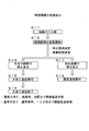
a.普通図柄の変動表示
普通図柄の変動表示は、図17に示すように、普通図柄作動ゲート16を遊技球が通過することを基づいて普通図柄表示部63において開始される(S1、S2)。この普通図柄の変動表示は、普通図柄表示部63に当り図柄若しくは外れ図柄を停止表示することで終了する。そして、普通図柄表示部63に当り図柄が停止表示されると(S3)、第2始動入賞装置17bが一定時間開放状態(第2状態)となり(S4)、普通図柄表示部63に外れ図柄が停止表示されると(S5)、第2始動入賞装置17bは閉鎖状態(第1状態)を維持する(S6)。
a. Normal Symbol Fluctuation Display Normal symbol variation display is started in the normal symbol display unit 63 based on the passing of the game ball through the normal
ここで、普通図柄表示部63に当り図柄が停止表示される場合において、開放延長機能が作動しない通常開放状態であるときには、第2始動入賞装置17bの開放時間が短く(例えば、0.2秒)されるため、第2始動入賞装置17bに遊技球が入球する可能性が低くなる。 Here, when the symbol is stopped and displayed on the normal symbol display unit 63, when the normal extension state in which the release extension function is not activated, the opening time of the second start winning device 17b is short (for example, 0.2 seconds). Therefore, the possibility of a game ball entering the second start winning device 17b is reduced.
また、前述のように、遊技球がステージ部21p上を転動することで、当該遊技球が第1始動入賞装置17aに入球する可能性が高くなるが、遊技領域11を流下する遊技球をステージ部21pに導く通路(ワープ通路)21wがメイン役物装置20の左側方に向かって開口している。更に、一般入賞装置48が遊技領域11における右側の領域(メイン役物装置20よりも右側)に配置され、しかも、第1始動入賞装置17aに遊技球が入球する可能性が、一般入賞装置48に遊技球が入球する可能性よりも高くなっている。このため、遊技機1の遊技状態が通常開放状態にあるとき、遊技者が遊技領域11における左側の領域(メイン役物装置20よりも左側)に向かって遊技球を発射する傾向(左打ちを行う傾向)が強くなる。
In addition, as described above, the game ball rolls on the stage portion 21p, so that there is a high possibility that the game ball will enter the first start winning device 17a. However, the game ball that flows down the
また、普通図柄表示部63に当り図柄が停止表示される場合において、開放延長機能が作動する開放延長状態であるときには、第2始動入賞装置17bの開放時間が長く(例えば、5秒)される。この場合、遊技者が、遊技領域11における左側の領域(メイン役物装置20よりも左側)に向かって遊技球を発射しても(左打ちを行っても)、右側の領域(メイン役物装置20よりも右側)に向かって遊技球を発射しても(右打ちを行っても)、始動入賞を生ずる可能性が高くなる。この場合、遊技者が右側の領域(メイン役物装置20よりも右側)に向かって遊技球を発射し、第2始動入賞装置17bに遊技球を入球させようとすると、一般入賞装置48に遊技球が入球する可能性を生ずることとなる。但し、第2始動入賞装置17bの開放時間が長くされ、第2始動入賞装置17bに遊技球が入球する可能性の方が、一般入賞装置48に遊技球が入球する可能性よりも高くなるため、遊技者は一般入賞装置48への入球を狙うのではなく、第2始動入賞装置17bへの入球を狙って遊技球を発射することになる。
When the symbol is stopped and displayed on the normal symbol display unit 63 and the release extension function is activated, the release time of the second start winning device 17b is extended (for example, 5 seconds). . In this case, even if the player launches a game ball (left-handed) toward the left area (left side of the main accessory device 20) in the
b.特別図柄の変動表示および演出図柄の変動表示
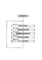
本遊技機1では、図17に示すように、遊技球が第1始動入賞装置17aに入球すること(以下、「第1始動入賞」という。)に基づいて、第1特別図柄表示部62aにおいて「第1特別図柄に係る変動表示」が実行され、遊技球が第2始動入賞装置17bに入球すること(以下、「第2始動入賞」という。)に基づいて、第2特別図柄表示部62bにおいて「第2特別図柄に係る変動表示」が実行される(S11、S12)。ここで、停止図柄および特別図柄(第1特別図柄、第2特別図柄)の変動時間は、対応する「特別図柄の変動表示」を開始する際に決定される。また、「第1特別図柄に係る変動表示」若しくは「第2特別図柄に係る変動表示」の実行に伴って、演出表示装置27において図柄変動演出が実行される。
b. As shown in FIG. 17, in this
「第1特別図柄に係る変動表示」および「第2特別図柄の変動表示」は、図5(b)に示すように、対応する特別図柄表示部(62a若しくは62b)を構成する7セグメント表示体によって、算用数字を構成できない不完全な図柄(以下、不完全図柄という。)の「循環表示」を行うことを内容とする。そして、「第1特別図柄に係る変動表示」が停止して停止図柄が表示されることによって、「第1始動入賞」に基づく当否判定(以下、「第1当否判定」という。)の結果が表示され、「第2特別図柄に係る変動表示」が停止して停止図柄が表示されることによって、「第2始動入賞」に基づく当否判定(以下、「第2当否判定」という。)の結果が表示される(図18のS14若しくはS17)。 As shown in FIG. 5B, the “variable display relating to the first special symbol” and the “variable display relating to the second special symbol” are the 7-segment display bodies constituting the corresponding special symbol display part (62a or 62b). The content is to perform “circular display” of an incomplete symbol (hereinafter referred to as an incomplete symbol) that cannot constitute a mathematical number. Then, when the “variable display relating to the first special symbol” is stopped and the stop symbol is displayed, the result of the success / failure determination based on the “first start winning award” (hereinafter referred to as “first success / failure determination”) is obtained. As a result of the display, the “variable display relating to the second special symbol” is stopped and the stop symbol is displayed, so that the result of the success / failure determination based on the “second start winning” (hereinafter referred to as “second determination determination”). Is displayed (S14 or S17 in FIG. 18).
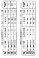
具体的には、図19に示すように、第1当否判定の結果が大当りの場合、「乱数抽選(振分抽選)」によって、大当り図柄が「16R通常大当りの発生を示す大当り図柄」、「8R確変大当りの発生を示す大当り図柄」および「8R通常大当りの発生を示す大当り図柄」のうち何れかに決定される。また、第2当否判定の結果が大当りの場合も、「乱数抽選(振分抽選)」によって、大当り図柄が、「16R確変大当りの発生を示す大当り図柄」、「8R通常大当りの発生を示す大当り図柄」および「16R通常大当りの発生を示す大当り図柄」のうち何れかに決定される。ここで、「大当り」は「特定の結果」の具体例を構成する。 Specifically, as shown in FIG. 19, when the result of the first success / failure determination is a big hit, the big hit symbol is “a big hit symbol indicating the occurrence of a 16R normal big hit” by “random number lottery (distribution lottery)”, “ It is determined to be either “big hit symbol indicating occurrence of 8R probability variation big hit” or “big hit symbol indicating occurrence of 8R normal big hit”. In addition, even if the result of the second winning / failing determination is a big hit, the “big random lottery (distribution lottery)” determines that the big hit symbol is “a big hit symbol indicating the occurrence of 16R probability variable big hit”, “a big hit indicating the occurrence of the 8R normal big hit It is determined as either “symbol” or “big jackpot symbol indicating occurrence of 16R normal jackpot”. Here, “big hit” constitutes a specific example of “specific result”.
また、図19に示すように、遊技機1の確率状態が低確率状態(通常確率状態)である場合には、第1当否判定および第2当否判定の何れにおいても、大当りを示す判定結果が導出される確率は約「1/350」とされ、遊技機1の確率状態が高確率状態である場合には、第1当否判定および第2当否判定の何れにおいても、大当りを示す判定結果(特定表示結果)が導出される確率は約「1/35」とされる。そして、特別図柄表示部(62a若しくは62b)に大当り図柄が停止表示されると、大当りが発生し、大当り遊技実行手段が駆動して大当り遊技が実行される。ここで、大当りは「特定の結果」の具体例を構成し、大当り遊技は「特定遊技」の具体例を構成する。
Further, as shown in FIG. 19, when the probability state of the
大当り遊技を開始すると、主制御部200Aが大入賞口ソレノイド31cの駆動及び駆動停止を行うことで「大入賞口31aを開閉する開閉動作」が実行される。そして、大当り遊技中の各ラウンド遊技においては、大入賞装置31に対して、大入賞口31aを1回だけ開放状態(第2状態)に変化させる開閉動作が施される。なお、大入賞口31aに規定入球数(10個)の遊技球が入球するか、或いは、大入賞口31aの開放時間が開放限度時間(30秒)に到達すると、ラウンド終了条件が成立して、実行中のラウンド遊技(大当りラウンド)を終了する。そして、大入賞装置31の開閉動作が、所定のインターバルを挟みつつ複数回繰り返されると大当り遊技を終了する。
When the big hit game is started, the
「16R確変大当り」若しくは「16R通常大当り」を生ずると「ラウンド遊技」の実行回数が「16回」の大当り遊技Aが実行され、「8R確変大当り」若しくは「8R通常大当り」を生ずると「ラウンド遊技」の実行回数が「8回」の大当り遊技Bが実行される。そして、大当り遊技Aおよび大当り遊技Bにおいては、各ラウンド遊技での大入賞口31aの開放限度時間が「30秒」とされているため、ラウンド遊技において大入賞口31aに規定入賞数(10個)の遊技球を入球させることが容易である。 When “16R probability variable big hit” or “16R normal big hit” is generated, “round game” is executed “16 times” big hit game A is executed, and when “8R probability variable big hit” or “8R normal big hit” is generated, “round The big hit game B with the number of executions of “game” being “8 times” is executed. In the big hit game A and the big hit game B, the open limit time of the big winning opening 31a in each round game is set to “30 seconds”. ) Is easy to enter.
つまり、本遊技機1では、遊技状態が大当り遊技状態(特定遊技状態)に移行すると、所定回数(8ラウンド若しくは16ラウンド)に亘る「ラウンド遊技」を実行する。そして、最終回の「ラウンド遊技」を終了すると、大当り遊技が終了する。また、本実施例では、図19に示すように、第1特別図柄表示部62a若しくは第2特別図柄表示部62bに停止表示される大当り図柄の態様に応じて、大当り遊技終了後の遊技機1の遊技状態が異なったものとなる。また、何れの大当り遊技においても、各ラウンド遊技で大入賞口31aに規定入賞数(10個)の遊技球が入球すると「150個」の遊技球が払い出されるため、「大当り遊技A」の払出予定賞球数は「2,400個」、「大当り遊技B」の払出予定賞球数は「1,200個」とされている。
That is, in the
但し、本遊技機1では、遊技領域11における右側の領域(メイン役物装置20よりも右側)に大入賞装置31(大入賞口31a)が配置されるため、大当り遊技中において、遊技者は遊技領域11における右側の領域に向かって遊技球を発射する。しかも、一般入賞口48が遊技領域11における右側の領域に配置されるため、大当り遊技中においては一般入賞口48に遊技球が入球する可能性を生ずることとなる。そして、一般入賞口48に遊技球が入球すると、大入賞装置31(大入賞口31a)の右側に位置する可変入賞装置35(可変入賞口35a)が開放状態となり、大入賞装置31(大入賞口31a)の周辺に到達した遊技球が、可変入賞装置35(可変入賞口35a)に入球する可能性を生ずることになる。
However, in this
そして、可変入賞装置35(可変入賞口35a)に遊技球が入球する毎に所定数(例えば、10個)の遊技球が払い出されるため、大当り遊技中に払い出される遊技球の数が上積みされる。また、遊技者は大当り遊技中において大入賞装置31(大入賞口31a)付近に視線を集中させて遊技を行うが、一般入賞口48に遊技球が入球することに伴って、大入賞装置31(大入賞口31a)の近傍(一体化されている)の可変入賞装置35(可変入賞口35a)が開放状態となると、遊技者に強いインパクトを与えることができる。
Each time a game ball enters the variable winning device 35 (variable winning port 35a), a predetermined number (for example, 10) of the game balls are paid out, so the number of game balls to be paid out during the big hit game is increased. The In addition, during the big hit game, the player concentrates his line of sight on the vicinity of the big winning device 31 (big winning port 31a), and the game ball enters the general winning
「16R確変大当り」若しくは「8R確変大当り」を生ずると、対応する大当り遊技を実行した後、確率変動手段が作動し、当否判定(第1当否判定、第2当否判定)の結果が大当りとなる確率が高確率とされる。また、「16R確変大当り」若しくは「8R確変大当り」を生ずると、対応する大当り遊技を実行した後には開放延長機能及び変動時間短縮機能が作動を開始する(遊技状態が通常変動状態から短縮変動状態に移行)。この当否判定(第1当否判定、第2当否判定)の結果が大当りとなる確率が高確率であって、開放延長機能及び変動時間短縮機能が作動する遊技状態(高確率開放延長状態)は、対応する大当り遊技の終了後に大当りを生ずることなく実行される図柄変動遊技の累積回数が「10,000回」になるまで継続される。但し、遊技機(パチンコ機)において通常定められる大当りの当選確率(大当り確率)を考慮すると、変動表示の累積回数が「10,000回」になるまで、当該遊技状態(高確率短縮変動状態)が継続することは、実質的に「次回の大当りを生ずるまで当該遊技状態(高確率短縮変動状態)」を意味する。よって、以下、当該ケースに関しては単に「次回の大当りを生ずるまで継続する」と表現する(図19を参照)。 When a “16R-probable big hit” or “8R-probable big hit” occurs, after executing the corresponding big-hit game, the probability varying means is activated, and the result of the determination (first win / no-go determination, second win / fail determination) becomes a big hit. Probability is high. In addition, when a “16R probability change big hit” or “8R probability change big hit” is generated, after the corresponding big hit game is executed, the open extension function and the variable time shortening function start operating (the game state is changed from the normal change state to the reduced change state). To). The game state (high probability open extension state) in which the probability of the success / failure determination (first win / fail determination, second win / fail determination) is a high probability and the open extension function and the variable time shortening function operate is as follows: The game is continued until the cumulative number of symbol variable games executed without generating a big hit after the end of the corresponding big hit game reaches “10,000 times”. However, in consideration of the jackpot winning probability (big hit probability) that is normally determined in a gaming machine (pachinko machine), the gaming state (high probability shortening variation state) until the cumulative number of times of the variable display becomes “10,000 times”. Continuing means substantially "the game state (high probability shortening variation state) until the next big hit". Therefore, hereinafter, the case is simply expressed as “continue until the next big hit occurs” (see FIG. 19).
一方、「16R通常大当り」若しくは「8R通常大当り」を生ずると、対応する大当り遊技を実行した後には当否判定(第1当否判定、第2当否判定)の結果が大当りとなる確率が低確率(通常確率)とされる。また、対応する大当り遊技の終了後には開放延長機能及び変動時間短縮機能が作動を開始する(遊技状態が通常変動状態から短縮変動状態に移行)。この当否判定(第1当否判定、第2当否判定)の結果が大当りとなる確率が低確率であって、開放延長機能及び変動時間短縮機能が作動する遊技状態(低確率短縮変動状態)は、対応する大当り遊技の終了後に大当りを生ずることなく実行される図柄変動表示の累積回数が「100回」になるまで継続される。 On the other hand, if a “16R normal big hit” or “8R normal big hit” occurs, the probability that the result of the hit / fail judgment (first hit / no-go judgment, second hit / no-go judgment) will be a big hit after executing the corresponding jackpot game is low ( Normal probability). In addition, after the corresponding jackpot game is over, the opening extension function and the variation time shortening function start operating (the game state shifts from the normal variation state to the shortened variation state). The gaming state (low probability shortening variation state) in which the probability that the result of this success / failure determination (first success / failure determination, second success / failure determination) is a big hit and the open extension function and the variable time shortening function operate is This is continued until the cumulative number of symbol variation displays executed without causing a big hit after the end of the corresponding big hit game reaches “100”.
また、演出図柄の変動表示(図柄変動演出)も、第1始動入賞若しくは第2始動入賞に基づいて開始される。この変動表示は演出表示装置27の表示画面27aにおいて実行され、主制御部200Aの制御の下で遊技上の演出を制御する「サブ制御部220A」によって、その変動態様と停止図柄とが決定される。そして、通常、これらの「演出図柄」を用いた変動表示は「特別図柄(本図柄)」と同一の時間だけ実行され、これらの「演出図柄」の停止図柄の表示内容(大当り、外れ等)は、第1特別図柄表示部62a若しくは第2特別図柄表示部62bにおける「特別図柄(本図柄)」の表示内容(大当り、外れ等)と矛盾を生じないものとされる。なお、演出図柄の停止図柄には「大当りを示す図柄(大当り図柄)」と「外れを示す図柄(外れ図柄)」とがある。
In addition, the display of fluctuation of the design symbol (design variation production) is also started based on the first start prize or the second start prize. This variation display is executed on the display screen 27a of the
図5(c)に示すように、「16R通常大当り」若しくは「8R通常大当り」の発生を示す図柄(16R通常大当り図柄、8R通常大当り図柄)は演出図柄表示領域27bに「同一の偶数数字」を3個並べて構成され、「16R確変大当り」若しくは「8R確変大当り」の発生を示す図柄(16R確変大当り図柄、8R確変大当り図柄)」は演出図柄表示領域27bに「同一の奇数数字」を3個並べて構成される。また、外れ図柄は、3つの演出図柄のうちの少なくとも1つが他と異なる数字とされる組み合わせによって構成される。 As shown in FIG. 5C, the symbols indicating the occurrence of “16R normal big hit” or “8R normal big hit” (16R normal big hit symbol, 8R normal big hit symbol) are displayed in the effect symbol display area 27b as “the same even number”. Are arranged side by side, and a symbol indicating the occurrence of “16R probability variation big hit” or “8R probability variation big hit” (16R probability variation big hit symbol, 8R probability variation big hit symbol) ”is set to 3 in the production symbol display area 27b. It is arranged side by side. Further, the off symbol is configured by a combination in which at least one of the three effect symbols is a different number.
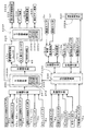
(5)主制御部200Aによる遊技制御
図20は、主制御基板200に搭載されたCPU201が実行する遊技制御処理の大まかな流れを示すフローチャートである。この遊技制御処理では、賞球払出処理(S80)、普通図柄遊技処理(S100)、普通電動役物遊技処理(S200)、特別図柄遊技処理(S300)、大当り遊技処理(S800)等の各処理が繰り返し実行されている。尚、本実施例の主制御基板200に搭載されたCPU201は、電源投入後、4msec周期のタイマ割込みが発生する毎に、図29のS80〜S800の処理を実行するように構成されている。そして、遊技制御処理を構成する各処理の中で、サブ制御基板220を初めとする各種制御基板に向けて各種の信号を送信する。こうすることにより、遊技機1全体の遊技が進行することになる。以下、図20に示す処理のうち、賞球払出処理(S80)のみについて説明する。
(5) Game Control by
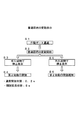
図21に示すように、主制御基板200に搭載されたCPU201は、入賞装置(第1始動入賞装置17a、第2始動入賞装置17b、大入賞装置31若しくは一般入賞装置45、46、47、48、可変入賞装置35)への遊技球の入球に基き、遊技球を賞球として払い出す処理(賞球払出処理)を行う(S80)。すなわち、「始動口入球検知スイッチ17s、17t」、「一般入賞口入球検知スイッチ45s、46s、47s、48s」、「可変入賞口入球検知スイッチ35s」、「大入賞口入球検知スイッチ31s」の状態を検知して遊技球が入球したか否かを判断する(S82、S86、S90、S94)。そして、遊技球が入球していた場合は、入球していた入賞装置17a、17b、45、46、47、48、35、31に対応する賞球情報を、主制御基板200に搭載されているRAM202の所定領域に記憶する(S84、S88、S92、S96)。
As shown in FIG. 21, the CPU 201 mounted on the main control board 200 has a winning device (a first starting winning device 17a, a second starting winning device 17b, a
つまり、遊技球が始動入賞装置17a、17bに入球した場合には(S82;YES)、始動入賞装置に対応する賞球情報を記憶し(S84)、一般入賞装置45、46、47、48に入球した場合には(S86;YES)、一般入賞装置45、46、47、48に対応する賞球情報を記憶する(S88)。また、可変入賞装置35に入球した場合には(S90;YES)、可変入賞装置35に対応する賞球情報を記憶し(S92)、大入賞装置31に入球した場合には(S94;YES)、大入賞装置31に対応する賞球情報を記憶する(S96)。
That is, when the game ball enters the start winning devices 17a and 17b (S82; YES), the winning ball information corresponding to the start winning device is stored (S84), and the general winning
そして、CPU201はRAM202上に記憶されている賞球情報に基づいて、賞球の払出信号を払出制御基板240に向かって出力する(S98)。また、RAM202上に、始動口入球検知スイッチ17s等への入賞情報が既に記憶されていた場合には、先に記憶されていた情報を含めて適切な払出個数を指定して、払出信号を出力する。ここで、始動入賞装置17a、17bに入賞した場合には「6個の払出個数を指定する払出信号」が出力され、一般入賞装置45、46、47、48に入球した場合には「10個の払出個数を指定する払出信号」が出力される。また、可変入賞装置35に入球した場合には「10個の払出個数を指定する払出信号」が出力され、大入賞装置31には「15個の払出個数を指定する払出信号」が出力される。
Then, the CPU 201 outputs a prize ball payout signal toward the
主制御部200Aから払出制御部240Aへ払出信号を出力するに際しては、先ず、払出制御部240A(払出制御基板240)に向かってストローブ信号を出力し、続いて信号データを出力する。これに対して、払出制御部240Aを構成する払出制御基板240に搭載されたCPUは、払出信号を受け取ると信号の内容を解釈し、賞球払出装置109に搭載された払出モータ109mに駆動信号を出力して賞球の払い出しを行う。そして、賞球払出装置109には、払い出された遊技球を検知する2つの払出スイッチ(前側払出スイッチ109a、後側払出スイッチ109b)が設けられているので、これらスイッチで遊技球を1球ずつ検知しながら、払出信号で指定された個数の賞球を払い出す処理を行う。
When outputting a payout signal from the
(8)実施例の効果
本遊技機1では、大当り遊技中に、大入賞口31aが入球不能状態(閉鎖状態)から入球可能状態(開放状態)に変化するだけでなく、一般入賞口48pへの遊技球の入球に基づき可変入賞口35aも、入球不能状態(閉鎖状態)から入球可能状態(開放状態)に変化し、可変入賞口35aへの遊技球の入球が可能となる。このように、大入賞口31aに入球しない遊技球が単に不変入賞口35aに入球し得るのではなく、一般入賞口48pへの入球に基づき、可変入賞装置35の開閉部材35bを前傾姿勢に変化させ、可変入賞口35aを入球可能状態(開放状態)に変化させる。このため、大入賞口31a周辺に配置される入賞口(一般入賞口48p、可変入賞口35a)の存在価値や、可変入賞口35aへの入球により獲得する賞球数の上積み(例えば、獲得賞球数の上積み)を遊技者に効果的に訴えることができる。
(8) Effects of the embodiment In the
すなわち、大入賞口31aを入球不能状態(閉鎖状態)から入球可能状態(開放状態)に変化させることを繰り返す大当り遊技中において、大入賞口31aの近傍(右隣り)に位置する可変入賞口35aをも入球不能状態(閉鎖状態)から入球可能状態(開放状態)に変化させ、この可変入賞口35aの状態変化を遊技者に訴える。つまり、この可変入賞口35aの状態変化を遊技者に視認させ、獲得賞球数の上積みのチャンスが到来したことを遊技者に認識させ、遊技者の期待感を高めるという効果(視覚的効果)を得ることができる。しかも、大当り遊技中に大入賞口31aを注視している遊技者にとっては、大入賞口31aの周囲に到達したものの大入賞口31aに入球できなった遊技球が可変入賞口35aに入球すること(拾われたこと)を視認することによって、大当り遊技中の獲得賞球数が上積みされたことを視覚によって認識できる。このため、遊技者はお得感を感じ易くなる。 In other words, in the big hit game in which the big winning opening 31a is repeatedly changed from the incapable entry state (closed state) to the enterable state (open state), the variable winning position is located near (right next to) the big winning opening 31a. The mouth 35a is also changed from a state where it is impossible to enter the ball (closed state) to a state where it is possible to enter the ball (open state), and the player is informed of the change in the state of the variable winning opening 35a. In other words, the effect that the player can visually recognize the change in the state of the variable winning opening 35a, recognize that the player has a chance to accumulate the number of winning balls, and increase the player's expectation (visual effect). Can be obtained. Moreover, for a player who is watching the big prize opening 31a during the big hit game, the game ball that has reached the circumference of the big prize opening 31a but cannot enter the big prize opening 31a enters the variable prize opening 35a. By visually recognizing what is being picked up (picked up), it is possible to visually recognize that the number of winning prize balls in the big hit game has been increased. For this reason, it becomes easy for a player to feel a profitable feeling.
また、本遊技機1では、大入賞口31a、一般入賞口48pおよび可変入賞口(第二種非電動役物)35aを、遊技盤10の盤面(遊技領域11)の右側領域を流下する遊技球が入球可能となるように設けるため、以下の効果を得ることもできる。仮に、一般入賞口48を遊技盤10の盤面(遊技領域11)の左側領域を流下する遊技球が入球可能となるように設け、可変入賞口48を遊技盤10の盤面(遊技領域11)の右側領域を流下する遊技球が入球可能となるように設けたとすると、可変入賞口48が入球不能状態(閉鎖状態)であるときに、盤面(遊技領域11)の左側領域を流下するように遊技球を発射し、可変入賞口48が入球可能状態となったときに、盤面(遊技領域11)の右側領域を流下するように遊技球を発射することが必要となる。
Further, in the
つまり、大当り遊技中(特定遊技中)において可変入賞口48への遊技球の入球に伴って獲得賞球数の上積みを得ようとするならば、可変入賞口48が入球可能状態(開放状態)に変化する度に、遊技球の発射強度(遊技球の流下位置)を変更することが必要となり、遊技が煩雑となったり、発射強度(遊技球の流下位置)の変更に伴って大入賞口31aへの入球率が低下する可能性がある。これに対して、本遊技機1では、大入賞口31a、一般入賞口48pおよび可変入賞口(第二種非電動役物)35aが何れも遊技領域11の右側領域を流下する遊技球が入球可能となるように設けるため、大当り遊技中(特定遊技中)に可変入賞口48pが入球可能となったときに、遊技球の発射強度(遊技球の流下位置)を変更する必要がない。よって、本遊技機1によると、大当り遊技(特定遊技)の実行に伴う利益(賞球獲得に関する利益)を確実に享受しつつ、獲得する賞球数の上積みを得ることができる。
In other words, during the big hit game (during a specific game), if an attempt is made to obtain an increase in the number of winning prize balls as the game balls enter the variable winning
更に、本遊技機1では、大入賞口31aの周辺に、一般入賞口48pおよび可変入賞口(第二種非電動役物)35aを付加しつつも、遊技者が不当に賞球を獲得することを防止できる。蓋し、本遊技機1では、一般入賞装置48(一般入賞口48p)が始動入賞装置17a、17b(始動口)よりも遊技球の入球可能性が低くなるように設けられている。よって、大当り遊技(特定遊技)が行われていない通常遊技時において、一般入賞口48を狙って遊技球を発射したとしても、それによるメリットが生じないため、通常遊技時に一般入賞口48および可変入賞口35aへの入球に基づく賞球を得ようとする行為を防止できるからである。
Furthermore, in this
なお、本実施例と異なり、ソフト的な制御によって通常遊技時には可変入賞口48pが入球可能状態とならないようにすることも考えられるが、このような構成を採用すると汎用性が低くなる。これに対して、本遊技機1によると、一般入賞口48pの入球可能性を始動口よりも低くすることで、通常遊技時に一般入賞口48pに向けて遊技球を発射するメリットが生じないものとなっているので、従来タイプの遊技機の既存のソフト制御を殆ど改変することなく、ハード面だけ対応することができる。
Unlike the present embodiment, it may be possible to prevent the variable winning opening 48p from entering a pitchable state during a normal game by software control. However, when such a configuration is adopted, versatility is lowered. On the other hand, according to this
また、本遊技機1では、大入賞口31aおよび可変入賞口35aを左右に並べた状態に配置する。このため、大入賞口31aに向かって流下する遊技球が通過する部位を避けた位置(大入賞口31aの鉛直上方等を避けた位置)に可変入賞口35aが設けられるため、遊技者は、大当り遊技の実行に伴う利益(賞球上の利益)を確実に享受しつつ、獲得する賞球数の上積みを図ることができる。また、可変入賞口35aを大入賞口31aの横方向に並んで設けられ、開放状態に変化した大入賞口31aの横方向で可変入賞口35aが開放状態に変化するため、遊技者に対して強いインパクトを与えることができる。
Further, in the
更に、大入賞口31aの開閉を行う開閉部材31bと、可変入賞口35aの開閉を行う開閉部材35bが同一の動作態様で動作するため、遊技者が一見しただけでは、大入賞口および可変入賞口の区別が付き辛くなる。このため、大入賞口31aが開放状態となっているとき、更に可変入賞口35aも開放状態となると、遊技者に対して強いインパクトを与えることができる。
Furthermore, since the opening / closing
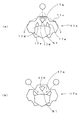
次に、実施例2の遊技機について説明する。この実施例2の遊技機は、図2の代わりに図22を用いる点と、図23が付加されている点が実施例1の遊技機と異なる。以下、実施例2の遊技機について、実施例1の遊技機との相違点を中心に説明する。 Next, a gaming machine according to the second embodiment will be described. The gaming machine of the second embodiment is different from the gaming machine of the first embodiment in that FIG. 22 is used instead of FIG. 2 and that FIG. 23 is added. Hereinafter, the gaming machine according to the second embodiment will be described focusing on differences from the gaming machine according to the first embodiment.
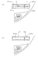
実施例2では、図22に示すように、大入賞装置31の前面部および可変入賞装置35の前面部によって一体的な意匠を構成したものである。具体的には、「大入賞装置31の前面部および可変入賞装置35の前面部に同一の図形を描くこと」、「両前面部に同一の着色を付すること」及び「両前面部に同一の模様を付すること」のうち1以上を行うことで、大入賞装置31の前面部および可変入賞装置35の前面部によって一体的な意匠を構成している。
In the second embodiment, as shown in FIG. 22, an integrated design is configured by the front portion of the
実施例2によると、実施例1の効果に加えて以下の効果を得ることができる。つまり、実施例2の遊技機では、大入賞装置31および可変入賞装置35が一体的であるが如き印象を遊技者に与え易い。そして、図23(a)に示すように、「大入賞口31a」が開放状態にあるとき、一般入賞口48pに遊技球が入球し、図23(b)に示すように、大入賞口31aの隣りの可変入賞口35aが開放状態となると、大入賞口31aを注視している遊技者に対して、あたかも大入賞口31aが横方向に拡大したような印象を与えることができる。このため、実施例1の遊技機によると、可変入賞口25aの存在価値をより効果的に訴えることができる。
According to the second embodiment, the following effects can be obtained in addition to the effects of the first embodiment. That is, in the gaming machine according to the second embodiment, although the
以上、本発明の実施の形態を説明したが、本発明はこれに限定されるものではなく、本発明の範囲を逸脱しない限り、特許請求の範囲において本発明を特定するための記載文言に限定されず、当業者がそれらから容易に置き換えられる範囲にも及び、かつ、当業者が通常有する知識に基づく改良を適宜付加することができる。 The embodiment of the present invention has been described above, but the present invention is not limited to this, and is limited to the description for specifying the present invention in the scope of the claims unless departing from the scope of the present invention. However, it is possible to appropriately add an improvement based on the knowledge that a person skilled in the art normally has, and to the extent that a person skilled in the art can easily replace them.
すなわち、各実施例では、大入賞装置31および可変入賞装置35を左右に略当接する状態に配置する態様を例示したが、図24(a)に示す変形例1のように、大入賞装置31と、可変入賞装置35とが所定距離だけ離間した状態に配置されてもよい。また、各実施例では、大入賞口31aおよび可変入賞口35aを水平方向に並べて配置する態様を例示したが、この変形例1に示すように、大入賞口31aおよび可変入賞口35aの高さ位置が異なっていてもよい。但し、大入賞口31aの上下幅をLとした場合、大入賞口31aおよび可変入賞口35の上下方向に沿った距離dを「上下幅Lの2倍以下」とすることが望ましい。
That is, in each of the embodiments, the embodiment in which the
更に、各実施例では、大入賞口31aおよび可変入賞口35aの開口形状を略同一形状とする態様(例えば、両者とも矩形とする態様)を例示したが、これらが異なっていてもよい。また、各実施例では、大入賞口31aおよび可変入賞口35aの上下幅を等しくしたが、この上下幅が異なっていてもよい。但し、大入賞口31aおよび可変入賞口35aの高さ位置を等しくしつつ、大入賞口31aおよび可変入賞口35aの上下幅を等しくし、更に、大入賞口31aの開閉を行う開閉部材31bと可変入賞口35aの開閉を行う開閉部材35bが同一の動作態様で動作すると、遊技者が一見しただけでは、大入賞口31aおよび可変入賞口35aの区別が付き辛くなる。このため、大入賞口31aが開放状態となっているとき、更に可変入賞口35aも開放状態となると、遊技者に対して更に強いインパクトを与えることができる。
Furthermore, in each of the embodiments, an example in which the opening shapes of the big winning opening 31a and the variable winning opening 35a are substantially the same shape (for example, an aspect in which both are rectangular) is illustrated, but they may be different. Moreover, in each Example, although the vertical width of the big prize opening 31a and the variable prize opening 35a was made equal, this vertical width may differ. However, the height positions of the big prize opening 31a and the variable prize opening 35a are made equal, the vertical width of the big prize opening 31a and the variable prize opening 35a are made equal, and the opening / closing
また、各実施例と異なり、大入賞口31aの開閉を行う開閉部材31bと可変入賞口35aの開閉を行う開閉部材35bの動作態様が異なっていてもよい。例えば、図24(b)に示す変形例2のように、大入賞口31aおよび可変入賞口35aのうち一方を開閉する開閉部材(例えば、開閉部材31b)が水平方向に沿った回動軸心回りに回動する開閉扉(各実施例と同様)で、他方(例えば、開閉部材35b)が前後に沿った回動軸心回りに回動する開閉羽根であってもよい。
Further, unlike each embodiment, the operation modes of the opening / closing
各実施例では、大入賞装置31や可変入賞装置35としてアタッカータイプ(水平方向に沿った回動軸心回りに回動する開閉扉で、入賞口を開閉するタイプ)を例示したが、大入賞装置31や可変入賞装置35としては、他の形式の入賞装置を例示できる。例えば、変形例2で例示した開閉羽根を備える入賞装置の他に、いわゆるチューリップ式の入賞装置(普通電動役物17dと同様に、左右に配設された一対の可動翼片と、一対の可動翼片を作動させるためのソレノイドとを備える入賞装置)を例示できる。
In each embodiment, an attacker type (a type that opens and closes a winning opening with an opening / closing door that rotates around a rotation axis along the horizontal direction) is exemplified as the
また、遊技盤10の盤面前方に向かって出没可能な球受部材と、球受部材の出没動(前後動)を行うソレノイドとを備える入賞装置を例示することもできる。この入賞装置を構成する球受部材は、上方に開放された略ポケット形状を備え、「上方に開口する入賞口」を前方側に設け、球受部材が遊技盤10の盤面前方に向かって突出したとき、球受部材(入賞口)によって上方から到達する遊技球を受入可能である。
In addition, a winning device including a ball receiving member that can be moved in and out toward the front of the surface of the
各実施例では、一般入賞口48pに1個の遊技球が入球すると可変入賞口35aが開放状態となる具体例を例示したが、一般入賞口48pに複数個の遊技球が入球すると可変入賞口35aが開放状態となる具体例を例示することもできる。また、各実施例では、可変入賞口35aが開放状態にあるとき、可変入賞口35aに1個の遊技球が入球すると可変入賞口35aが閉鎖状態となる具体例を例示したが、可変入賞口35aを開放状態から閉鎖状態に変化させる個数を複数個とすることもできる。例えば、図25の変形例3に示すように、開閉部材35bの下端部に遊技球を保持する保持部35vを設け、この保持部35vが所定個数(例えば、2個)の遊技球を保持すると、開閉部材35bにおいて、その回動軸心35Jよりも下方側が上方側よりも重くなるようにすれば、可変入賞口35aを開放状態から閉鎖状態に変化させる個数を複数個とすることができる。特に、可変入賞口35aを開放状態から閉鎖状態に変化させる個数が、前述のラウンド遊技における大入賞口31aへの規定入球数(10個)となったり、規定入球数(10個)に近い個数(例えば、規定入球数の5割以上、好ましくは、5割以上)とすると、「一般入賞口48pに遊技球を入球させると、大当りラウンドが1ラウンド増える」という印象を遊技者に与えることができるため、遊技興趣の向上を図ることができる。
In each embodiment, a specific example in which the variable winning opening 35a is opened when one game ball enters the general winning opening 48p is illustrated. However, the variable winning opening 35a is variable when a plurality of gaming balls enter the general winning opening 48p. A specific example in which the winning opening 35a is in an open state can also be illustrated. In each embodiment, when the variable winning opening 35a is in the open state, a specific example is illustrated in which the variable winning opening 35a is closed when one game ball enters the variable winning opening 35a. The number of the mouths 35a that change from the open state to the closed state may be plural. For example, as shown in
更に、上述した各実施例および変形例では、遊技ホールの島設備から供給される遊技球を「貸球」や「賞球」として利用し、遊技盤に設けられた各種入賞口(第1始動口、第2始動口、大入賞口等)への遊技球の入球に応じて所定数の賞球を払い出すことによって、遊技の結果としての利益(遊技価値)を遊技者に付与する遊技機1に本発明を適用した例を説明したが、「賞球の払い出し」とは異なる形態で遊技上の利益(遊技価値)を付与するタイプの遊技機にも、本発明を適用することができる。
Furthermore, in each of the above-described embodiments and modifications, the game balls supplied from the island facilities of the game hall are used as “rental balls” or “prize balls”, and various winning holes (first start) provided on the game board are used. Games that give the player a profit (game value) as a result of the game by paying out a predetermined number of prize balls in response to the entry of game balls into the mouth, the second start opening, the big prize opening, etc. Although the example in which the present invention is applied to the
そのようなタイプの遊技機として、各種入賞口への遊技球の入球が発生することで、その入球に対応する利益の量(遊技価値の大きさ)を示すデータを主制御部あるいは払出制御部のRAMに記憶することによって、遊技上の利益(遊技価値)を遊技者に付与する遊技機を例示でき、この場合にも、上記実施例と同様の効果を得ることができる。なお、遊技上の利益(遊技価値)をデータ化して遊技者に付与するタイプの遊技機としては、遊技機に内蔵された複数個の遊技球を循環させて使用する遊技機、具体的には、各種入賞口あるいはアウト口を経て遊技盤の裏面に排出された遊技球を、再度、発射位置に戻して発射するように構成された遊技機(いわゆる封入式遊技機)を例示できる。この種の遊技機(いわゆる封入式遊技機)においては、例えば、入賞口に遊技球が入球する毎に、例えば、入球した入賞口毎に定められた賞球量を示すデータを記憶することによって、遊技の結果としての遊技価値を遊技者に付与することができる。 As such a type of gaming machine, when a game ball is entered into various winning openings, data indicating the amount of profit (the magnitude of the game value) corresponding to the winning ball is given to the main control unit or the payout By storing it in the RAM of the control unit, it is possible to exemplify a gaming machine that gives a game profit (game value) to a player. In this case, the same effect as in the above embodiment can be obtained. As a type of gaming machine in which gaming profit (game value) is converted into data and given to the player, a gaming machine that circulates and uses a plurality of gaming balls built in the gaming machine, specifically, Examples of the game machine (so-called enclosed game machine) configured to return the game ball discharged to the back surface of the game board through various winning holes or out holes to the launch position and launch it again. In this type of game machine (so-called enclosed game machine), for example, every time a game ball enters a winning opening, for example, data indicating a prize ball amount determined for each winning opening is stored. Thus, the game value as a result of the game can be given to the player.
本発明は、遊技機を製造、販売等する分野において利用できる。 The present invention can be used in the field of manufacturing and selling gaming machines.
1;遊技機(弾球遊技機)、
10;遊技盤、
11;遊技領域、
17a;第1始動入賞装置、
17b;第2始動入賞装置、
17p;第1始動口(始動口)、
17q;第2始動口(始動口)、
31;大入賞装置、
31a;大入賞口(第1可変入球口)、
31b;開閉部材(第1作動片)、
35;可変入賞装置、
35b;開閉部材(第2作動片)、
35a;可変入賞口(第2可変入球口)、
48p;一般入賞口(一般入球口)。
1; gaming machine (ball game machine),
10: Game board,
11: Game area,
17a; first start winning device,
17b; second start winning device,
17p; first start port (start port),
17q; second start port (start port),
31; Grand prize-winning device,
31a; large winning entrance (first variable entrance),
31b; opening and closing member (first operating piece),
35; Variable winning device,
35b; opening and closing member (second operating piece),
35a; Variable winning entrance (second variable entrance),
48p: General winning entrance (general entrance).
Claims (1)
前記始動口への遊技球の入球に基づいて識別情報の変動表示を行う表示装置と、
前記遊技領域のうち右側領域を流下する遊技球が入球可能であって、前記変動表示の結果として特定の結果が得られた場合に遊技球が入球可能となるように構成された第1可変入球口と、
前記右側領域を流下する遊技球が入球可能であって、前記始動口よりも遊技球の入球可能性が低くなるように構成された一般入球口と、
前記右側領域を流下する遊技球が入球可能であって、前記一般入球口への遊技球の入球に基づき遊技球が入球可能となるように構成されるとともに、前記第1可変入球口の横方向に並んで設けられた第2可変入球口と、
所定の動作態様で動作することで、前記第1可変入球口を遊技球が入球不能な入球不能状態から遊技球が入球可能な入球可能状態に変化させる第1作動片と、
前記第1作動片と同一の動作態様で動作することで、前記第2可変入球口を遊技球が入球不能な入球不能状態から遊技球が入球可能な入球可能状態に変化させる第2作動片と、
を備えることを特徴とする遊技機。 A start opening into which a game ball flowing down the left side of the game area formed on the game board surface can enter;
A display device for performing a variable display of identification information based on a game ball entering the start opening;
A first configuration is such that when a game ball flowing down the right region of the game area can enter and a specific result is obtained as a result of the change display, the game ball can enter the game area. Variable entrance,
A game ball that flows down the right side region is capable of entering, and a general ball entrance that is configured such that the game ball is less likely to enter than the start port; and
The game balls flowing down the right area is a possible ball entrance, based on said input ball game balls to the general ball entrance opening game ball is configured to be ball entrance Rutotomoni, the first variable input A second variable entry opening provided side by side in the lateral direction of the entry opening ;
A first actuating piece that changes the first variable entry port from an inaccessible state in which a game ball cannot enter into an enterable state in which a game ball can enter by operating in a predetermined operation mode;
By operating in the same mode of operation as the first operating piece, the second variable entrance is changed from an inaccessible state in which a game ball cannot enter into an enterable state in which a game ball can enter. A second working piece;
Gaming machine, characterized in that it comprises a.
Priority Applications (1)
| Application Number | Priority Date | Filing Date | Title |
|---|---|---|---|
| JP2013094920A JP5861663B2 (en) | 2013-04-30 | 2013-04-30 | Game machine |
Applications Claiming Priority (1)
| Application Number | Priority Date | Filing Date | Title |
|---|---|---|---|
| JP2013094920A JP5861663B2 (en) | 2013-04-30 | 2013-04-30 | Game machine |
Publications (2)
| Publication Number | Publication Date |
|---|---|
| JP2014213111A JP2014213111A (en) | 2014-11-17 |
| JP5861663B2 true JP5861663B2 (en) | 2016-02-16 |
Family
ID=51939437
Family Applications (1)
| Application Number | Title | Priority Date | Filing Date |
|---|---|---|---|
| JP2013094920A Expired - Fee Related JP5861663B2 (en) | 2013-04-30 | 2013-04-30 | Game machine |
Country Status (1)
| Country | Link |
|---|---|
| JP (1) | JP5861663B2 (en) |
Families Citing this family (5)
| Publication number | Priority date | Publication date | Assignee | Title |
|---|---|---|---|---|
| JP6260525B2 (en) * | 2014-11-30 | 2018-01-17 | 株式会社三洋物産 | Game machine |
| JP6260524B2 (en) * | 2014-11-30 | 2018-01-17 | 株式会社三洋物産 | Game machine |
| JP2016168224A (en) * | 2015-03-13 | 2016-09-23 | 株式会社サンセイアールアンドディ | Game machine |
| JP2017018255A (en) * | 2015-07-09 | 2017-01-26 | タイヨーエレック株式会社 | Game machine |
| JP2018038707A (en) * | 2016-09-09 | 2018-03-15 | 株式会社ソフイア | Game machine |
Family Cites Families (3)
| Publication number | Priority date | Publication date | Assignee | Title |
|---|---|---|---|---|
| JP4381135B2 (en) * | 2003-12-25 | 2009-12-09 | 株式会社ソフィア | Game machine |
| JP2006271452A (en) * | 2005-03-28 | 2006-10-12 | Daiichi Shokai Co Ltd | Game machine |
| JP5635867B2 (en) * | 2010-10-19 | 2014-12-03 | 株式会社平和 | Game machine set board |
-
2013
- 2013-04-30 JP JP2013094920A patent/JP5861663B2/en not_active Expired - Fee Related
Also Published As
| Publication number | Publication date |
|---|---|
| JP2014213111A (en) | 2014-11-17 |
Similar Documents
| Publication | Publication Date | Title |
|---|---|---|
| JP5742818B2 (en) | Game machine | |
| JP5617897B2 (en) | Game machine | |
| JP5934970B2 (en) | Game machine | |
| JP5861663B2 (en) | Game machine | |
| JP5435049B2 (en) | Game machine | |
| JP2007185285A (en) | Fraud prevention device of pinball game machine | |
| JP5617896B2 (en) | Game machine | |
| JP6712980B2 (en) | Amusement machine | |
| JP7505819B2 (en) | Gaming Machines | |
| JP5435048B2 (en) | Game machine | |
| JP5218472B2 (en) | Game machine | |
| JP2016174675A (en) | Pinball game machine | |
| JP6452641B2 (en) | Game machine | |
| JP4247322B2 (en) | Bullet ball machine | |
| JP2009112329A (en) | Pinball game machine | |
| JP6452640B2 (en) | Game machine | |
| JP6281718B2 (en) | Game machine | |
| JP7505820B2 (en) | Gaming Machines | |
| JP2021013437A (en) | Game machine | |
| JP6951779B2 (en) | Pachinko machine | |
| JP2000167210A (en) | Pachinko game machine | |
| JP6635349B2 (en) | Gaming machine | |
| JP6712981B2 (en) | Amusement machine | |
| JP6712979B2 (en) | Amusement machine | |
| JP7020771B2 (en) | Pachinko machine |
Legal Events
| Date | Code | Title | Description |
|---|---|---|---|
| A131 | Notification of reasons for refusal |
Free format text: JAPANESE INTERMEDIATE CODE: A131 Effective date: 20150317 |
|
| A521 | Written amendment |
Free format text: JAPANESE INTERMEDIATE CODE: A523 Effective date: 20150514 |
|
| TRDD | Decision of grant or rejection written | ||
| A01 | Written decision to grant a patent or to grant a registration (utility model) |
Free format text: JAPANESE INTERMEDIATE CODE: A01 Effective date: 20151124 |
|
| A61 | First payment of annual fees (during grant procedure) |
Free format text: JAPANESE INTERMEDIATE CODE: A61 Effective date: 20151207 |
|
| R150 | Certificate of patent or registration of utility model |
Ref document number: 5861663 Country of ref document: JP Free format text: JAPANESE INTERMEDIATE CODE: R150 |
|
| LAPS | Cancellation because of no payment of annual fees |