JP5856419B2 - Fluid transmission device for vehicles - Google Patents
Fluid transmission device for vehicles Download PDFInfo
- Publication number
- JP5856419B2 JP5856419B2 JP2011214880A JP2011214880A JP5856419B2 JP 5856419 B2 JP5856419 B2 JP 5856419B2 JP 2011214880 A JP2011214880 A JP 2011214880A JP 2011214880 A JP2011214880 A JP 2011214880A JP 5856419 B2 JP5856419 B2 JP 5856419B2
- Authority
- JP
- Japan
- Prior art keywords
- damper
- inner peripheral
- outer peripheral
- shell
- output
- Prior art date
- Legal status (The legal status is an assumption and is not a legal conclusion. Google has not performed a legal analysis and makes no representation as to the accuracy of the status listed.)
- Expired - Fee Related
Links
Images


Classifications
-
- F—MECHANICAL ENGINEERING; LIGHTING; HEATING; WEAPONS; BLASTING
- F03—MACHINES OR ENGINES FOR LIQUIDS; WIND, SPRING, OR WEIGHT MOTORS; PRODUCING MECHANICAL POWER OR A REACTIVE PROPULSIVE THRUST, NOT OTHERWISE PROVIDED FOR
- F03B—MACHINES OR ENGINES FOR LIQUIDS
- F03B15/00—Controlling
- F03B15/02—Controlling by varying liquid flow
- F03B15/04—Controlling by varying liquid flow of turbines
-
- F—MECHANICAL ENGINEERING; LIGHTING; HEATING; WEAPONS; BLASTING
- F01—MACHINES OR ENGINES IN GENERAL; ENGINE PLANTS IN GENERAL; STEAM ENGINES
- F01D—NON-POSITIVE DISPLACEMENT MACHINES OR ENGINES, e.g. STEAM TURBINES
- F01D25/00—Component parts, details, or accessories, not provided for in, or of interest apart from, other groups
- F01D25/24—Casings; Casing parts, e.g. diaphragms, casing fastenings
-
- F—MECHANICAL ENGINEERING; LIGHTING; HEATING; WEAPONS; BLASTING
- F16—ENGINEERING ELEMENTS AND UNITS; GENERAL MEASURES FOR PRODUCING AND MAINTAINING EFFECTIVE FUNCTIONING OF MACHINES OR INSTALLATIONS; THERMAL INSULATION IN GENERAL
- F16H—GEARING
- F16H41/00—Rotary fluid gearing of the hydrokinetic type
- F16H41/24—Details
-
- F—MECHANICAL ENGINEERING; LIGHTING; HEATING; WEAPONS; BLASTING
- F16—ENGINEERING ELEMENTS AND UNITS; GENERAL MEASURES FOR PRODUCING AND MAINTAINING EFFECTIVE FUNCTIONING OF MACHINES OR INSTALLATIONS; THERMAL INSULATION IN GENERAL
- F16H—GEARING
- F16H45/00—Combinations of fluid gearings for conveying rotary motion with couplings or clutches
- F16H45/02—Combinations of fluid gearings for conveying rotary motion with couplings or clutches with mechanical clutches for bridging a fluid gearing of the hydrokinetic type
- F16H2045/0205—Combinations of fluid gearings for conveying rotary motion with couplings or clutches with mechanical clutches for bridging a fluid gearing of the hydrokinetic type two chamber system, i.e. without a separated, closed chamber specially adapted for actuating a lock-up clutch
-
- F—MECHANICAL ENGINEERING; LIGHTING; HEATING; WEAPONS; BLASTING
- F16—ENGINEERING ELEMENTS AND UNITS; GENERAL MEASURES FOR PRODUCING AND MAINTAINING EFFECTIVE FUNCTIONING OF MACHINES OR INSTALLATIONS; THERMAL INSULATION IN GENERAL
- F16H—GEARING
- F16H45/00—Combinations of fluid gearings for conveying rotary motion with couplings or clutches
- F16H45/02—Combinations of fluid gearings for conveying rotary motion with couplings or clutches with mechanical clutches for bridging a fluid gearing of the hydrokinetic type
- F16H2045/0221—Combinations of fluid gearings for conveying rotary motion with couplings or clutches with mechanical clutches for bridging a fluid gearing of the hydrokinetic type with damping means
- F16H2045/0252—Combinations of fluid gearings for conveying rotary motion with couplings or clutches with mechanical clutches for bridging a fluid gearing of the hydrokinetic type with damping means having a damper arranged on input side of the lock-up clutch
-
- F—MECHANICAL ENGINEERING; LIGHTING; HEATING; WEAPONS; BLASTING
- F16—ENGINEERING ELEMENTS AND UNITS; GENERAL MEASURES FOR PRODUCING AND MAINTAINING EFFECTIVE FUNCTIONING OF MACHINES OR INSTALLATIONS; THERMAL INSULATION IN GENERAL
- F16H—GEARING
- F16H45/00—Combinations of fluid gearings for conveying rotary motion with couplings or clutches
- F16H45/02—Combinations of fluid gearings for conveying rotary motion with couplings or clutches with mechanical clutches for bridging a fluid gearing of the hydrokinetic type
- F16H2045/0273—Combinations of fluid gearings for conveying rotary motion with couplings or clutches with mechanical clutches for bridging a fluid gearing of the hydrokinetic type characterised by the type of the friction surface of the lock-up clutch
- F16H2045/0294—Single disk type lock-up clutch, i.e. using a single disc engaged between friction members
-
- Y—GENERAL TAGGING OF NEW TECHNOLOGICAL DEVELOPMENTS; GENERAL TAGGING OF CROSS-SECTIONAL TECHNOLOGIES SPANNING OVER SEVERAL SECTIONS OF THE IPC; TECHNICAL SUBJECTS COVERED BY FORMER USPC CROSS-REFERENCE ART COLLECTIONS [XRACs] AND DIGESTS
- Y02—TECHNOLOGIES OR APPLICATIONS FOR MITIGATION OR ADAPTATION AGAINST CLIMATE CHANGE
- Y02E—REDUCTION OF GREENHOUSE GAS [GHG] EMISSIONS, RELATED TO ENERGY GENERATION, TRANSMISSION OR DISTRIBUTION
- Y02E10/00—Energy generation through renewable energy sources
- Y02E10/20—Hydro energy
Description
本発明は、車両に備えられる流体伝動装置に関し、特にその流体伝動装置に備えられるダンパ装置をポンプシェルの外側に設ける構造に関するものである。 The present invention relates to a fluid transmission device provided in a vehicle, and more particularly to a structure in which a damper device provided in the fluid transmission device is provided outside a pump shell.
車両の動力源と自動変速機との間の動力伝達経路に設けられ、その動力源により発生させられたトルクを流体を介して上記自動変速機の入力軸へ伝達する車両用流体伝動装置が知られている。たとえば、エンジン等の駆動源によって一軸心まわりに回転駆動させられるポンプ翼車と、そのポンプ翼車によって送り出された作動流体によって上記一軸心まわりに回転させられるタービン翼車とを備えたフルードカップリングや、たとえば特許文献1および特許文献2に記載されている、上記ポンプ翼車とタービン翼車との間で上記一軸心まわりに回転可能に配置されているステータ翼車をさらに備えたトルクコンバータがそれである。 A vehicle fluid transmission device is known which is provided in a power transmission path between a vehicle power source and an automatic transmission and transmits torque generated by the power source to the input shaft of the automatic transmission via a fluid. It has been. For example, a fluid including a pump impeller rotated around a single axis by a driving source such as an engine, and a turbine impeller rotated around the single axis by a working fluid sent out by the pump impeller Further, a stator impeller described in, for example, Patent Document 1 and Patent Document 2, which is rotatably arranged around the one axis between the pump impeller and the turbine impeller, is provided. That is the torque converter.
上記のような車両用流体伝動装置においては、ポンプ翼車の外殻を構成するポンプシェルはエンジン側へ突き出すセンターピースを中心部に備え、そのセンターピースが、クランク軸の軸端面に開口する芯出し穴に嵌め入れられることにより、流体伝動装置が芯出しされている。 In the vehicular fluid transmission apparatus as described above, the pump shell that forms the outer shell of the pump impeller includes a center piece that projects toward the engine side, and the center piece opens to the shaft end surface of the crankshaft. The fluid transmission device is centered by being fitted into the outlet hole.
ところで、上記特許文献1および特許文献2に示すように、ダンパ装置をクランク軸の軸端に孤影されたドライブプレートとポンプシェルとの間に設ける場合は、ダンパ装置により許容される相対回転の範囲で、ポンプシェルから突き出すセンターピースとそれが嵌め入れられるようにクランク軸の軸端面に開口する芯出し穴との間で相対回転が発生して相互に摺動する。このため、センターピースまたはそれが嵌め入れられる芯出し穴に摩耗が発生して芯出し精度が低下し、車両の振動が大きくなるというおそれがあった。また、これに対して、特許文献2に示されるように、センターピースと芯出し穴との間にベアリングを設けたり、ブッシュを設けることが提案されているが、部品点数の増加、加工工数や組みつけ工数が増加するという不都合が発生する。 By the way, as shown in the said patent document 1 and the patent document 2, when providing a damper apparatus between the drive plate and the pump shell which were obscured by the axial end of a crankshaft, the range of the relative rotation permitted by a damper apparatus Thus, relative rotation occurs between the center piece protruding from the pump shell and the centering hole opened in the shaft end surface of the crankshaft so that the center piece is fitted and slides on each other. For this reason, there is a possibility that the center piece or the centering hole into which the center piece is fitted is worn, the centering accuracy is lowered, and the vibration of the vehicle is increased. On the other hand, as shown in Patent Document 2, it has been proposed to provide a bearing or a bush between the center piece and the centering hole, but the increase in the number of parts, the processing man-hours, There is a disadvantage that the assembly man-hour increases.
本発明は、以上の事情を背景として為されたものであり、その目的とするところは、センターピースと芯出し穴との間にベアリングやブッシュを用いることなくポンプシェルの芯出し精度が維持される車両用流体伝動装置を提供することにある。 The present invention has been made against the background of the above circumstances. The purpose of the present invention is to maintain the centering accuracy of the pump shell without using a bearing or a bush between the center piece and the centering hole. It is providing the fluid transmission device for vehicles.
本発明は、以上の事情を背景として為されたものであり、その要旨とするところは、(a)駆動源からのトルクが入力されるポンプシェル内に複数の羽根を有するポンプ翼車と、該ポンプ翼車の羽根に対向する位置に設けられた複数の羽根と該羽根を支持するハブ部と有して出力軸の軸端部に支持され、該ポンプ翼車の羽根から送り出される作動流体を受けて回転させられるタービン翼車と、前記出力軸の軸心方向において前記駆動源と前記ポンプシェルとの間に設けられ、該駆動源の出力軸に連結され、かつ、弾性部材を介してトルクをダンパ出力部材に伝達するように構成されたダンパ入力部材とそのダンパ入力部材内に収容された弾性部材と前記ポンプシェルに連結された前記ダンパ出力部材とを有して該駆動源からのトルクの脈動を抑制して該ポンプシェルに伝達するダンパ装置とを備える車両用流体伝動装置であって、(b)前記ポンプシェルに固定され、前記ダンパ出力部材が連結されるセット部材と、(c)前記駆動源の前記出力軸の軸端部にボルトにより固定され、前記駆動源の出力軸から前記ポンプシェルに向かって突き出し、前記ダンパ入力部材と相互に嵌合されている芯出し部材と、を含み、(d)前記ダンパ出力部材は前記ダンパ入力部材内に収容されて前記弾性部材を介して該ダンパ入力部材からのトルクが伝達される外周部と、前記セット部材の前記駆動源側の端面に固定された内周部とを有し、(e)前記ダンパ入力部材は、前記弾性部材およびダンパ出力部材の外周部を収容する外周部と、該ダンパ出力部材の内周部よりも内周側へ曲成された円筒状ボス部とを有し、(f)該円筒状ボス部の外周面と前記セット部材の内周面との間に軸受装置が嵌め着けられ、(g)該円筒状ボス部の内周面と前記芯出し部材の外周面とが嵌合されていることにある。
The present invention has been made against the background of the above circumstances, the gist of which is (a) a pump impeller having a plurality of blades in a pump shell to which torque from a drive source is input; A working fluid that has a plurality of blades provided at positions opposed to the blades of the pump impeller and a hub portion that supports the blades, is supported by the shaft end portion of the output shaft, and is delivered from the blades of the pump impeller And the turbine impeller rotated in response to the shaft, and provided between the drive source and the pump shell in the axial direction of the output shaft, connected to the output shaft of the drive source, and via an elastic member A damper input member configured to transmit torque to the damper output member; an elastic member housed in the damper input member; and the damper output member coupled to the pump shell. Torque pulsation A vehicular fluid transmission device comprising: a damper device for controlling and transmitting to the pump shell; (b) a set member fixed to the pump shell and connected to the damper output member; and (c) the drive is bolted to the shaft end of the output shaft of the source, projecting towards the pump shell from the output shaft of the driving source, see containing and a centering member is fitted to the damper input member and interoperability (D) The damper output member is housed in the damper input member and is provided on an outer peripheral portion to which torque from the damper input member is transmitted via the elastic member, and on an end surface of the set member on the drive source side. (E) the damper input member includes an outer peripheral portion that houses the outer peripheral portion of the elastic member and the damper output member, and an inner peripheral side of the inner peripheral portion of the damper output member. Rounded circle (F) a bearing device is fitted between the outer peripheral surface of the cylindrical boss portion and the inner peripheral surface of the set member, and (g) the inner peripheral surface of the cylindrical boss portion. And the outer peripheral surface of the centering member are fitted .
このように構成された車両用流体伝動装置によれば、ポンプシェルに固定されたセット部材にダンパ出力部材が固定されるとともに、ダンパ入力部材と前記駆動源の出力軸から前記ポンプシェルに向かって突き出す芯出し部材とが相互に嵌合されていることから、ダンパ入力部材と駆動源の出力軸に固定された芯出し部材とは相対回転なく相互に嵌合されて芯出しされているので、センターピースと芯出し穴との間にベアリングやブッシュを用いることなくポンプシェルの芯出し精度が維持される。また、前記ダンパ出力部材は、前記ダンパ入力部材内に収容されて前記弾性部材を介して該ダンパ入力部材からのトルクが伝達される外周部と、前記セット部材の前記駆動源側の端面に固定された内周部とを有し、前記ダンパ入力部材は、前記弾性部材およびダンパ出力部材の外周部を収容する外周部と、該ダンパ出力部材の内周部よりも内周側へ曲成された円筒状ボス部とを有し、該円筒状ボス部の外周面と前記セット部材の内周面との間に前記軸受装置が嵌め着けられ、該円筒状ボス部の内周面と前記芯出し部材の外周面とが嵌合されている。このため、センターピースと芯出し穴との間にベアリングやブッシュを用いることなくポンプシェルの芯出し精度が維持されるとともに、軸受装置はセット部材の内周側に設けられているので、ダンパ出力部材の板厚に拘わらず、セット部材より外周側の搭載スペースが確保され、ダンパの搭載性が高められる利点がある。
According to the fluid transmission device for a vehicle configured as described above, the damper output member is fixed to the set member fixed to the pump shell, and from the damper input member and the output shaft of the drive source toward the pump shell. Since the protruding centering members are fitted to each other, the damper input member and the centering member fixed to the output shaft of the driving source are fitted and centered without mutual rotation. The centering accuracy of the pump shell is maintained without using a bearing or bush between the center piece and the centering hole. The damper output member is fixed to an outer peripheral portion that is accommodated in the damper input member and to which torque from the damper input member is transmitted via the elastic member, and an end surface on the drive source side of the set member. And the damper input member is bent to the inner peripheral side with respect to the outer peripheral portion accommodating the outer peripheral portion of the elastic member and the damper output member, and to the inner peripheral side of the inner peripheral portion of the damper output member. A cylindrical boss portion, and the bearing device is fitted between an outer peripheral surface of the cylindrical boss portion and an inner peripheral surface of the set member, and the inner peripheral surface of the cylindrical boss portion and the core The outer peripheral surface of the extension member is fitted. For this reason, the centering accuracy of the pump shell is maintained without using a bearing or bush between the center piece and the centering hole, and the bearing device is provided on the inner peripheral side of the set member. Regardless of the plate thickness of the member, there is an advantage that a mounting space on the outer peripheral side from the set member is secured and the mountability of the damper is improved.
ここで、好適には、前記駆動源の出力軸は、エンジンのクランク軸であり、前記ダンパ入力部材は前記クランク軸の軸端に固定されたドライブプレートに連結され、前記ダンパ入力部材に嵌合された前記芯出し部材は前記クランク軸の軸端に前記エンジンから離れる側に突き出して固定され、前記ダンパ入力部材は、前記セット部材により前記軸受装置を介して前記ダンパ出力部材と相対回転可能に支持されていることを特徴とする。このようにすれば、ポンプシェルに固設されたセット部材に固定されたダンパ出力部材と、駆動源の出力軸に固定されたダンパ入力部材とが、軸受装置により芯出しされて相対回転可能とされるので、ダンパ入力部材とともにそれと相対回転するダンパ出力部材も芯出しされる。
Preferably, the output shaft of the drive source is an engine crankshaft, and the damper input member is connected to a drive plate fixed to a shaft end of the crankshaft and is fitted to the damper input member. the said centering member which is fixed protruding on the side away from the engine to the shaft end of the crankshaft, the damper input member, the setting member by rotatably relative said damper output member via the bearing device It is characterized by being supported. In this way, the damper output member fixed to the set member fixed to the pump shell and the damper input member fixed to the output shaft of the drive source are centered by the bearing device and can be relatively rotated. Therefore, the damper input member that rotates relative to the damper input member is also centered.
また、好適には、前記セット部材には、前記複数本のセットボルトが螺合される複数の雌ねじ穴が前記軸心方向に形成されており、前記ダンパ出力部材の内周部は、該セットボルトによりセット部材に締結され、前記ダンパ入力部材の該セットボルトに対向する部分には貫通孔が形成されている。このようにすれば、ダンパ出力部材の板厚に拘わらず、セット部材より外周側の搭載スペースが確保され、ダンパの搭載性が高められる利点がある。 Preferably, the set member is formed with a plurality of female screw holes into which the plurality of set bolts are screwed in the axial direction, and the inner periphery of the damper output member is A through hole is formed in a portion of the damper input member that is fastened to the set member by a bolt and faces the set bolt. In this way, regardless of the thickness of the damper output member, there is an advantage that the mounting space on the outer peripheral side from the set member is secured and the mountability of the damper is improved.
また、好適には、前記軸受装置は、前記セット部材の内周面と同時に前記ダンパ出力部材の内周部の内周面にも嵌合されている。このようにすれば、ダンパ入力部材とダンパ出力部材との相互の芯出し精度が高められ、一層、車両の振動が抑制される。 Preferably, the bearing device is fitted to the inner peripheral surface of the inner peripheral portion of the damper output member simultaneously with the inner peripheral surface of the set member. In this way, the mutual centering accuracy between the damper input member and the damper output member is enhanced, and the vibration of the vehicle is further suppressed.
以下、本発明の一実施例を図面を参照しつつ詳細に説明する。 Hereinafter, an embodiment of the present invention will be described in detail with reference to the drawings.
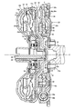
図1は本発明の一実施例の車両用流体伝動装置であるトルクコンバータ10の構成を説明する断面図であり、図2はトルクコンバータ10が車両の円筒状のハウジング8内に設けられた状態を示している。トルクコンバータ10は、ポンプ翼車( ポンプインペラ) 12、タービン翼車( タービンランナ) 14、ロックアップクラッチ16、一方向クラッチ18、およびステータ翼車20を備え、駆動源として機能するエンジン21のクランク軸22から入力されるトルクを増幅し、トルクコンバータ10の出力軸として機能する変速機24の入力軸26から出力する。
FIG. 1 is a cross-sectional view illustrating a configuration of a
ポンプ翼車12は、円盤状のフロントシェル12aおよびリヤシェル12bから成り、エンジン21のクランク軸22とドライブプレート32およびダンパ装置34を介して連結されてそのクランク軸22と同じ回転数で軸心Cまわりに回転させられるポンプシェル12cと、リヤシェル12bの外周部内側に周方向に重なるように複数枚配設されているポンプブレード12dとを備えている。タービン翼車14は、入力軸26の軸端部にスプライン嵌合され且つ摺動リング12eを介してフロントシェル12aに相対回転可能に当接させられた円盤状のハブ部14aと、ハブ部14aの中央から突設されて入力軸26の軸端部にスプライン嵌合された円筒軸部14bと、ハブ部14aの外周部においてポンプブレード12dに対向するように周方向に重なるように複数枚固定されたタービンブレード14dとを備え、入力軸26と共に軸心Cまわりに回転するように設けられている。ステータ翼車20は、ポンプ翼車12のポンプブレード12dとタービン翼車14のタービンブレード14dとの間に位置するステータブレード20dが外周部に形成された円板部20aと、円板部20aの内周部に形成され、一方向クラッチ18が嵌め入れられた円筒部20bとを備え、ハウジング8に固定された非回転部材である円筒状固定軸28により、一方向クラッチ18を介して軸心Cまわりに回転可能に支持されている。フロント側の第1スラストベアリング44がステータ翼車20とタービン翼車14のハブ部14aとの間に介在させられるとともに、リヤ側の第2スラストベアリング46がステータ翼車20とリヤシェル12bとの間に介在させられているため、ステータ翼車20の軸心方向位置が定められている。
The
ハウジング8内には、変速機24を収容する空間とトルクコンバータ10を収容する空間とを隔てるための隔壁24aが設けられており、その隔壁24aには、油圧ポンプ30が設けられている。油圧ポンプ30は、隔壁24aに固定されたポンプボデー30aとそれに固定されたポンプカバー30bと、それらの間に形成された空間内に回転可能に収容されて互いに噛み合うインナーリングギヤ30cおよびアウタリングギヤ30dとを備え、そのインナーリングギヤ30cには、ポンプ翼車12のリヤシェル12bの内周部から突設された円筒軸12fの軸端に相対回転不能に嵌合されることにより、油圧ポンプ30がエンジン21によって回転駆動されるようになっている。上記油圧ポンプ30すなわちポンプボデー30aは、隔壁24aからトルクコンバータ10側すなわちエンジン21側又は入力側へ円錐状に突き出している。入力軸26は、図示しないベアリングを介して隔壁24aにより回転可能に支持された状態で、トルクコンバータ10を収容する空間内へ突き出されており、トルクコンバータ10を支持している。
In the housing 8, a
ポンプ翼車12のポンプシェル12cの出力側すなわち変速機24側を構成するリヤシェル12bの外周部および入力側すなわちエンジン21側を構成するフロントシェル12aの外周部は、その出力側すなわち変速機24側へ突き出すようにオフセットさせられている。このため、リヤシェル12bの内周部は入力側へ凹んだ凹状とされており、ポンプボデー30aの先端部を受け入れている。すなわち、ポンプボデー30aの先端部は、リヤシェル12bの外周部と径方向において重なっている。これにより、スペース効率が高められ、トルクコンバータ10の軸心C方向の寸法が短縮されている。
The outer peripheral portion of the
このため、変速機24側へ突き出すリヤシェル12bの外周部の内壁面に配設されているポンプ翼車12のポンプブレード12dも出力側へオフセットさせられているため、ステータ翼車20のステータブレード20dおよびタービン翼車14のタービンブレード14dも、ポンプ翼車12のポンプブレード12dと一定の相対位置関係を維持しつつ、同様に出力側すなわち変速機24側へオフセットさせられている。本実施例では、ステータ翼車20の円板部20aがその外周部が円筒部20bよりも変速機24側に位置する円錐形状に形成されることにより、ステータ翼車20のステータブレード20dが、一方向クラッチ18に対して径方向において重ならないように出力側へオフセットさせられている。また、タービン翼車14のハブ部14aは、その外周部が一方向クラッチ18と径方向に重なる円錐形状に形成されることにより、タービン翼車14のタービンブレード14dが一方向クラッチ18に対して径方向において一部は重ならないが一部重なるように、出力側へオフセットさせられている。
For this reason, since the
ロックアップクラッチ16は、入力軸26の軸端部に相対回転不能に嵌合されたタービン翼車14のハブ部14aの中央から突設された円筒軸部14bの外周面に中心部が摺動可能に嵌合され、且つタービン翼車14のタービンシェル14cから突設された係合突起14eと相対回転不能に係合した円板状のピストン16aと、そのピストン16aの外周部、または、フロントシェル12aの内側のうちその外周部に対向する部分に固着され、タービン翼車14とポンプ翼車12とを摩擦力によって直接的に相互に連結する環状の摩擦材16bとを備えている。前述のように、ポンプ翼車12のポンプシェル12cの入力側すなわちエンジン21側を構成するフロントシェル12aの外周部は、出力側すなわち変速機24側へ突き出すようにオフセットさせられているため、ピストン16aの外周部も同様に出力側すなわち変速機24側へ突き出すようにオフセットさせられて、フロントシェル12aやタービン翼車14との干渉が防止されるようになっている。このように、ロックアップクラッチ16のピストン16aおよびフロントシェル12aの外周部は、ロックアップクラッチ16のピストン16aの外周部およびそれに固着された摩擦材16bが一方向クラッチ18と径方向において重なるように、出力側へオフセットされている。
The lock-up clutch 16 has a central portion that slides on the outer peripheral surface of the
エンジン21のクランク軸22の軸端にボルト22aにより固定されたドライブプレート32は、円板状部32aと、図示しないスタータモータのピニオンと噛み合うために円板状部32aの外周部に固定されたリングギヤ32bとを備えている。ダンパ装置34は、そのドライブプレート32とポンプシェル12cの前部を構成するフロントシェル12aとの間に設けられている。また、プレス部品である環状の芯出し部材33は、その内周部が上記ドライブプレート32の内周部と重ねられた状態で上記ボルト22aによりクランク軸22の軸端に固定されている。
The
ダンパ装置34は、軸心Cと同心の円環状の環状セット部材35を介してフロントシェル12aに内周部が固定され、ダンパ装置34の周方向に長手状となるようにコイル状に巻回され且つ相互に同心に構成された2種類の大径ダンパスプリング36aおよび小径ダンパスプリング36bを受け入れる外周側に開いた切欠38aが外周部の複数箇所に等間隔で形成された円板状のドリブンプレート38と、フロントシェル12aに固定された上記環状セット部材35により環状のベアリング40を介して軸心Cまわりに回転可能に支持されると共にドライブプレート32の円板状部32aに固定され、一対の大径ダンパスプリング36aおよび小径ダンパスプリング36bの外周を覆うようにして受け入れるための周方向に伸びる円柱状空間が周方向の複数箇所に等間隔で形成されたダンパーシェル42とを備え、ドリブンプレート38とダンパーシェル42との間の回転位相のずれに応じて大径ダンパスプリング36aおよび小径ダンパスプリング36bが周方向すなわちその長手方向に圧縮されることで、エンジン21から伝達されるトルクの脈動が吸収されるようになっている。本実施例では、上記ダンパーシェル42がダンパ入力部材として機能し、上記ドリブンプレート38がダンパ出力部材として機能し、上記環状のベアリング40が軸受装置として機能し、上記大径ダンパスプリング36aおよび小径ダンパスプリング36bが弾性部材として機能している。
The
ダンパ装置34において、それを構成する部品の中で最も質量の大きいダンパーシェル42は、クランク軸端に固定された芯出し部材33に支持されてその芯出し精度が高められ、回転時に発生する振動が抑制されるようになっている。すなわち、ドリブンプレート38は、ダンパーシェル42内に収容されて大径ダンパスプリング36aおよび小径ダンパスプリング36bを介してダンパーシェル42からのトルクが伝達される外周部と、環状セット部材35の駆動源側の端面に固定された内周部とを有し、ダンパーシェル42は、大径ダンパスプリング36a、小径ダンパスプリング36bおよびドリブンプレート38の外周部を収容する外周部42aと、そのドリブンプレート38の内周部よりも内周側へ曲成された円筒状ボス部42bとを有し、円筒状ボス部42bの外周面と環状セット部材35の内周面との間に環状のベアリング40が嵌め着けられている。また、この環状のベアリング40のアウタレースはドリブンプレート38の内周部の内周面にも嵌合され、ダンパーシェル42とドリブンプレート38との間の芯出し精度も高められている。そして、ドリブンプレート38の内周部は、セットボルト52により環状セット部材35に締結され、ダンパーシェル42のセットボルト52に対応する部分には、セットボルト52を締結させる工具を通過させるための貫通孔42cが形成されている。このような構成により、ドリブンプレート38の板厚に拘わらず、環状セット部材35より外周側の搭載スペースが確保され、ダンパ装置34の搭載姓が高められている。
In the
ダンパーシェル42は、上記複数の円柱状空間とそれら複数の円柱状空間を周方向に連通させる連通空間とから成るスプリング収容空間Sと、少なく大径ダンパスプリング36aの径よりも小さな軸心C方向の開口幅を有して連通空間が内周側に開口する内周側開口Kとを、備えている。ドリブンプレート38の外周部はその開口K内に差し入れられており、そのドリブンプレート38の両面においてリベット48によって固着された一対のばね鋼製のシール部材50が上記開口Kを封止している。上記スプリング収容空間S内には、たとえばグリスのような潤滑剤が封入されている。
The
前述のように、ポンプ翼車12のポンプシェル12cの入力側すなわちエンジン21側を構成するフロントシェル12aの外周部は、出力側すなわち変速機24側へ突き出すようにオフセットさせられているため、フロントシェル12aの外周部の入力側すなわちエンジン21側には、ドライブプレート32との間に、環状空間Xが形成されており、上記ダンパ装置34はその環状空間X内に配置されている。ダンパ装置34は、その大径ダンパスプリング36aおよび小径ダンパスプリング36bの中心を通る軸心C方向の中心位置PDが入力軸26の軸端、タービン翼車14の内周部に位置する円筒軸部14bの入力側の端面、およびフロントシェル12aの内周部の入力側先端よりも出力側に位置していることから明らかなように、入力軸26の軸端部、およびタービン翼車14の内周部すなわち円筒軸部14b、およびフロントシェル12aの内周部と径方向において重なるように位置させられている。これにより、ポンプシェル12cの入力側を構成するフロントシェル12aの内周部は、外周部よりも入力側すなわちエンジン21側へ突き出しており、径方向においてダンパ装置34のほぼ全部と重なっている。
As described above, the outer peripheral portion of the
この結果、ダンパ装置34は、従来のものに比較して、大径ダンパスプリング36aおよび小径ダンパスプリング36bを外周側に位置させることにより、コイル径が大きく且つコイル線径の大きいものとすることができ、トルク変化に対してねじれ角が大きく柔らかな、高いダンパ性能を備えている。ダンパ装置34がこのような高いダンパ性能を備えていることにより、トルク振動が効率的に低減されるので、燃焼効率の良い低回転且つ高負荷の運転領域でエンジン21を作動させることができる。また、ロックアップクラッチ16による直結状態での走行時において、トルクコンバータ10はピストン16aおよびタービン翼車14を介して入力軸26により支持されるが、ダンパ装置34と入力軸26とが重なっているので、振れなどの外乱が入力されたとき、ダンパ装置34の振れが抑制されてより安定的にダンパ装置34が支持される。また、上記のように、ダンパ装置34は、その軸心C方向の中心位置PDが入力軸26の軸端およびタービン翼車14の円筒軸部14bと径方向において重なるように位置させられているため、トルクコンバータ10を支持して一方向クラッチ18および入力軸26を嵌合する組み付け時において、高い作業性が得られる。
As a result, the
図3は、溶接などによりフロントシェル12aに固着された環状セット部材35を、エンジン21側から見た正面図である。図3において、環状セット部材35には、ドリブンプレート38をフロントシェル12aに固着するために、そのドリブンプレート38を通したセットボルト52が螺合される複数の雌ねじ穴54が貫通して形成されており、前記リベット48との干渉を防止しうるための複数の干渉防止穴56が止り穴として形成されている。そして、環状セット部材35のフロントシェル12a側の面であって上記干渉防止穴56が設けられている位置には、径方向に貫通する貫通溝58がそれぞれ形成されている。この貫通溝58は、環状セット部材35の外周面と環状ベアリング40とフロントシェル12aとの間の内周側に開口する環状空間SSに貯留された水を、遠心力或いは重力により外周側へ排出する連通路として機能している。
FIG. 3 is a front view of the
ところで、本実施例のポンプシェル12cの中央部には、クランク軸22の端面に形成された芯出し穴22b内に嵌合させて芯出しを行なうセンターピースが設けられていない。図3では従来設けられていたセンターピースが破線で示されている。本実施例ではそれに替わる芯出し構造として、クランク軸22の軸端には、ボルト22aで締結された環状の芯出し部材33が変速機24側へ突き出すように設けられている。この芯出し部材33の外周面33aがダンパーシェル42の内周部に設けられた円筒状ボス部42bの内周面に嵌合され、芯出しが行なわれている。ダンパーシェル42はドライブプレート32を介してクランク軸22に連結されているので、相互に嵌合された芯出し部材33とダンパーシェル42の円筒状ボス部42bとは相対回転しない。
By the way, the center part of the
上述のように、本実施例のトルクコンバータ10によれば、ポンプシェル12cに固定された環状セット部材35にドリブンプレート(ダンパ出力部材)38が固定されるとともに、ダンパーシェル42の内周部に設けられた円筒状ボス部42bとエンジン21のクランク軸22からポンプシェル12cに向かって突き出す芯出し部材33とが相互に嵌合されていることから、(ダンパ入力部材)と駆動源の出力軸に固定された芯出し部材とは相対回転なく相互に嵌合されて芯出しされているので、センターピースと芯出し穴との間にベアリングやブッシュを用いることなくポンプシェルの芯出し精度が維持される。
As described above, according to the
また、本実施例のトルクコンバータ10によれば、ダンパーシェル(ダンパ入力部材)42はクランク軸22の軸端に固定されたドライブプレート32に連結され、ダンパーシェル42の内周部に設けられた円筒状ボス部42bに嵌合された芯出し部材33はクランク軸22の軸端にエンジン21から離れる側に突き出して固定され、ダンパーシェル42は、環状セット部材35により環状のベアリング(軸受装置)40を介して相対回転可能に支持されている。このため、ポンプシェル12cに固設された環状セット部材35に固定されたドリブンプレート(ダンパ出力部材)38と、クランク軸22に固定されたダンパーシェル42とが、環状のベアリング40により芯出しされて相対回転可能とされるので、ダンパーシェル42とともにそれと相対回転するドリブンプレート38も芯出しされる。
Further, according to the
また、本実施例のトルクコンバータ10によれば、ドリブンプレート(ダンパ出力部材)38は、ダンパーシェル(ダンパ入力部材)42内に収容されて大径ダンパスプリング(弾性部材)36aおよび小径ダンパスプリング(弾性部材)36bを介してダンパーシェル42からのトルクが伝達される外周部と、環状セット部材35のエンジン21側の端面にセットボルト52により固定された内周部とを有するものであり、ダンパーシェル(ダンパ入力部材)42は、大径ダンパスプリング36aおよび小径ダンパスプリング、およびドリブンプレート38の外周部を収容する外周部と、ドリブンプレート38内周部よりも内周側へ曲成された円筒状ボス部42bとを有するものであり、その円筒状ボス部42bの外周面と環状セット部材35の内周面との間に環状のベアリング40が嵌め着けられ、円筒状ボス部42bの内周面と芯出し部材33の外周面とが嵌合さている。このため、センターピースと芯出し穴2bとの間にベアリングやブッシュを用いることなくポンプシェルの芯出し精度が維持される。また、環状のベアリング40は環状セット部材35の内周側に設けられているので、ドリブンプレート38の板厚に拘わらず、環状セット部材35より外周側の搭載スペースが確保され、ダンパ装置34の搭載性が高められる利点がある。
Further, according to the
また、本実施例のトルクコンバータ10によれば、環状セット部材35には、複数本のセットボルト52が螺合される複数の雌ねじ穴54が軸心C方向に形成されており、ドリブンプレート(ダンパ出力部材)38の内周部は、セットボルト52により環状セット部材35に締結され、ダンパーシェル(ダンパ入力部材)42のセットボルト52に対向する部分には貫通孔42cが形成されている。このため、ドリブンプレート38の板厚に拘わらず、環状セット部材35より外周側の搭載スペースが確保され、ダンパ装置34の搭載性が高められる利点がある。
Further, according to the
また、本実施例のトルクコンバータ10によれば、ダンパ装置34において、それを構成する部品の中で最も質量の大きいダンパーシェル42は、クランク軸端に固定された芯出し部材33に支持されてその芯出し精度が高められ、回転時に発生する振動が抑制される。
Further, according to the
また、本実施例のトルクコンバータ10によれば、環状のベアリング40は、環状セット部材35の内周面と同時にドリブンプレート38の内周部の内周面にも嵌合されているので、ダンパーシェル42とドリブンプレート38との相互の芯出し精度が高められ、一層、車両の振動が抑制される。
Further, according to the
以上、本発明の実施例を図面に基づいて詳細に説明したが、本発明はその他の態様においても適用される。 As mentioned above, although the Example of this invention was described in detail based on drawing, this invention is applied also in another aspect.
たとえば、前述の実施例では、車両用流体伝動装置として、トルクコンバータ10が例示されていたが、フルードカップリングであってもよい。
For example , in the above-described embodiment, the
また、前述の実施例の環状セット部材35は、周方向において連続した部材であったが、周方向に分割された複数のセクタ或いはブロックから構成されたセット部材であってもよいし、個々に雌ねじ54が形成されて周方向に配列されたセットブロックであってもよい。
Further, the
また、前述の実施例では、軸受装置としてボールベアリングから成る環状のベアリング40が用いられていたが、メタルベアリング、ローラベアリングなどで構成されてもよい。
In the above-described embodiment, the
また、前述の実施例において、ダンパ装置34は、2種類の大径ダンパスプリング36aおよび小径ダンパスプリング36bを有するものであったが、1種類、或いは3種類のダンパスプリングを有したり、ダンパスプリングの大きさや位置の異なるものなど、他の構造或いは形式のものであってもよい。
In the above-described embodiment, the
また、前述の実施例において、ポンプ翼車12の羽根12d、タービン翼車14の羽根14d、ステータ翼車20の羽根20dが出力側へオフセットされていたが、そのオフセット量は、必ずしも、ステータ翼車20の羽根20dが一方向クラッチ18と重ならない位置までオフセットさせられていなくてもよい。
In the above-described embodiment, the
なお、上述したのはあくまでも一実施形態であり、本発明は当業者の知識に基づいて種々の変更、改良を加えた態様で実施することができる。 The above description is only an embodiment, and the present invention can be implemented in variously modified and improved forms based on the knowledge of those skilled in the art.
10:トルクコンバータ(車両用流体伝動装置)
12:ポンプ翼車
12c:ポンプシェル
14:タービン翼車
16:ロックアップクラッチ
21:エンジン( 駆動源)
32:ドライブプレート
33:芯出し部材
34:ダンパ装置
35:環状セット部材(セット部材)
36a大径ダンパスプリング(弾性部材)
36b:小径ダンパスプリング(弾性部材)
38:ドリブンプレート(ダンパ出力部材)
40:環状のベアリング(軸受装置)
42a:ダンパーシェルの外周部
42b:ダンパーシェルの円筒状ボス部
42c:ダンパーシェルの貫通孔
52:セットボルト
54:雌ねじ穴
10: Torque converter (Vehicle fluid transmission device)
12:
32: Drive plate 33: Centering member 34: Damper device 35: Ring set member (set member)
36a large-diameter damper spring (elastic member)
36b: Small-diameter damper spring (elastic member)
38: Driven plate (damper output member)
40: Annular bearing (bearing device)
42a: Damper shell outer
Claims (4)
前記ポンプシェルに固定され、前記ダンパ出力部材が連結されるセット部材と、
前記駆動源の前記出力軸の軸端部にボルトにより固定され、前記駆動源の出力軸から前記ポンプシェルに向かって突き出し、前記ダンパ入力部材と相互に嵌合されている芯出し部材と、を含み、
前記ダンパ出力部材は前記ダンパ入力部材内に収容されて前記弾性部材を介して該ダンパ入力部材からのトルクが伝達される外周部と、前記セット部材の前記駆動源側の端面に固定された内周部とを有し、
前記ダンパ入力部材は、前記弾性部材およびダンパ出力部材の外周部を収容する外周部と、該ダンパ出力部材の内周部よりも内周側へ曲成された円筒状ボス部とを有し、
該円筒状ボス部の外周面と前記セット部材の内周面との間に軸受装置が嵌め着けられ、
該円筒状ボス部の内周面と前記芯出し部材の外周面とが嵌合されていることを特徴とする車両用流体伝動装置。 A pump impeller having a plurality of blades in a pump shell to which torque from a driving source is input, a plurality of blades provided at positions facing the blades of the pump impeller, and a hub portion supporting the blades A turbine impeller supported by a shaft end portion of the output shaft and rotated by receiving a working fluid delivered from the blades of the pump impeller, and the drive source and the pump shell in the axial direction of the output shaft And a damper input member connected to the output shaft of the drive source and configured to transmit torque to the damper output member via the elastic member, and an elastic member housed in the damper input member A vehicular fluid transmission device comprising: a damper device having a member and the damper output member coupled to the pump shell, and suppressing a pulsation of torque from the drive source and transmitting the pulsation of the torque to the pump shell;
A set member fixed to the pump shell and connected to the damper output member;
A centering member fixed to a shaft end portion of the output shaft of the drive source by a bolt, protruding from the output shaft of the drive source toward the pump shell, and fitted to the damper input member; seen including,
The damper output member is housed in the damper input member and is fixed to an outer peripheral portion to which torque from the damper input member is transmitted via the elastic member, and an inner surface fixed to the driving source side end surface of the set member And a peripheral portion,
The damper input member has an outer peripheral portion that accommodates outer peripheral portions of the elastic member and the damper output member, and a cylindrical boss portion that is bent to the inner peripheral side from the inner peripheral portion of the damper output member,
A bearing device is fitted between the outer peripheral surface of the cylindrical boss portion and the inner peripheral surface of the set member,
A fluid transmission device for a vehicle , wherein an inner peripheral surface of the cylindrical boss portion and an outer peripheral surface of the centering member are fitted .
前記ダンパ入力部材は前記クランク軸の軸端に固定されたドライブプレートに連結され、
前記ダンパ入力部材に嵌合された前記芯出し部材は前記クランク軸の軸端に前記エンジンから離れる側に突き出して固定され、
前記ダンパ入力部材は、前記セット部材により前記軸受装置を介して前記ダンパ出力部材と相対回転可能に支持されていることを特徴とする請求項1の車両用流体伝動装置。 The output shaft of the drive source is an engine crankshaft,
The damper input member is connected to a drive plate fixed to an end of the crankshaft,
The centering member fitted to the damper input member protrudes and is fixed to the shaft end of the crankshaft away from the engine,
The damper input member, the setting member by the bearing device for a vehicle hydraulic power transmission device according to claim 1, characterized in that it is rotatably supported the damper output member relative through.
前記ダンパ出力部材の内周部は、該セットボルトによりセット部材に締結され、
前記ダンパ入力部材の該セットボルトに対向する部分には貫通孔が形成されていることを特徴とする請求項1または2の車両用流体伝動装置。 In the set member, a plurality of female screw holes into which the plurality of set bolts are screwed are formed in the axial direction,
The inner periphery of the damper output member is fastened to the set member by the set bolt,
The damper input member according to claim 1 or 2 for a vehicle hydraulic power transmission, characterized in that the through hole is formed in a portion facing said set bolt.
The bearing device for a vehicle according to claim 1 or any one of the 3, characterized in that is also fitted to the inner peripheral surface of the inner peripheral portion of the same time the damper output member and the inner peripheral surface of the setting member Fluid transmission device.
Priority Applications (5)
| Application Number | Priority Date | Filing Date | Title |
|---|---|---|---|
| JP2011214880A JP5856419B2 (en) | 2011-09-29 | 2011-09-29 | Fluid transmission device for vehicles |
| US14/348,104 US9695797B2 (en) | 2011-09-29 | 2012-09-28 | Vehicular fluid power transmitting device |
| EP12772419.3A EP2761207B1 (en) | 2011-09-29 | 2012-09-28 | Vehicular fluid power transmitting device |
| CN201280047811.6A CN103917806B (en) | 2011-09-29 | 2012-09-28 | Vehicle fluid transmission means |
| PCT/IB2012/001913 WO2013046008A1 (en) | 2011-09-29 | 2012-09-28 | Vehicular fluid power transmitting device |
Applications Claiming Priority (1)
| Application Number | Priority Date | Filing Date | Title |
|---|---|---|---|
| JP2011214880A JP5856419B2 (en) | 2011-09-29 | 2011-09-29 | Fluid transmission device for vehicles |
Publications (3)
| Publication Number | Publication Date |
|---|---|
| JP2013076419A JP2013076419A (en) | 2013-04-25 |
| JP2013076419A5 JP2013076419A5 (en) | 2014-07-03 |
| JP5856419B2 true JP5856419B2 (en) | 2016-02-09 |
Family
ID=47018273
Family Applications (1)
| Application Number | Title | Priority Date | Filing Date |
|---|---|---|---|
| JP2011214880A Expired - Fee Related JP5856419B2 (en) | 2011-09-29 | 2011-09-29 | Fluid transmission device for vehicles |
Country Status (5)
| Country | Link |
|---|---|
| US (1) | US9695797B2 (en) |
| EP (1) | EP2761207B1 (en) |
| JP (1) | JP5856419B2 (en) |
| CN (1) | CN103917806B (en) |
| WO (1) | WO2013046008A1 (en) |
Families Citing this family (3)
| Publication number | Priority date | Publication date | Assignee | Title |
|---|---|---|---|---|
| JP6011564B2 (en) | 2014-03-04 | 2016-10-19 | トヨタ自動車株式会社 | Release mechanism of friction clutch |
| US9574649B2 (en) * | 2014-12-05 | 2017-02-21 | Valeo Embrayages | Hydrokinetic torque coupling device having turbine-piston lockup clutch, and related methods |
| US10281020B2 (en) * | 2016-12-21 | 2019-05-07 | Valeo Embrayages | Torque-coupling device with torsional vibration damper and oneway turbine clutch, and method for making the same |
Family Cites Families (12)
| Publication number | Priority date | Publication date | Assignee | Title |
|---|---|---|---|---|
| JP3155286B2 (en) * | 1991-03-20 | 2001-04-09 | マツダ株式会社 | Torque converter |
| JP2598472Y2 (en) | 1991-12-16 | 1999-08-09 | 株式会社ユニシアジェックス | Power transmission device |
| JP2578916Y2 (en) * | 1992-10-20 | 1998-08-20 | 株式会社ユニシアジェックス | Power transmission for automatic transmission |
| US5398562A (en) * | 1993-05-18 | 1995-03-21 | General Motors Corporation | Engine/transmission drive connection with bridging starter gear |
| DE19826351C2 (en) * | 1998-06-12 | 2001-06-28 | Daimler Chrysler Ag | Drive arrangement with hydrodynamic torque converter and two dampers |
| JP2003106399A (en) * | 2001-09-28 | 2003-04-09 | Jatco Ltd | Torque converter |
| DE102005034933A1 (en) | 2005-07-27 | 2007-02-01 | Zf Friedrichshafen Ag | Connection arrangement for drive, clutch has axial securing device coaxial with drive output for limiting clutch mobility relative to drive, displacement arrangement axially fixed to part on drive output to protrude into stop working area |
| JP4929947B2 (en) | 2006-09-25 | 2012-05-09 | マツダ株式会社 | Torque converter |
| JP2009058105A (en) * | 2007-09-03 | 2009-03-19 | Toyota Motor Corp | Torque converter |
| JP4784631B2 (en) | 2008-09-30 | 2011-10-05 | トヨタ自動車株式会社 | Driving force transmission device |
| JP2010255753A (en) | 2009-04-24 | 2010-11-11 | Toyota Motor Corp | Power transmission device |
| CN101988569B (en) * | 2010-11-16 | 2013-02-27 | 浙江吉利汽车研究院有限公司 | Automobile dual-mass hydraulic torque converter |
-
2011
- 2011-09-29 JP JP2011214880A patent/JP5856419B2/en not_active Expired - Fee Related
-
2012
- 2012-09-28 CN CN201280047811.6A patent/CN103917806B/en active Active
- 2012-09-28 EP EP12772419.3A patent/EP2761207B1/en active Active
- 2012-09-28 US US14/348,104 patent/US9695797B2/en active Active
- 2012-09-28 WO PCT/IB2012/001913 patent/WO2013046008A1/en active Application Filing
Also Published As
| Publication number | Publication date |
|---|---|
| WO2013046008A1 (en) | 2013-04-04 |
| JP2013076419A (en) | 2013-04-25 |
| WO2013046008A8 (en) | 2013-08-15 |
| US9695797B2 (en) | 2017-07-04 |
| EP2761207B1 (en) | 2018-02-28 |
| US20140234093A1 (en) | 2014-08-21 |
| CN103917806B (en) | 2016-09-14 |
| CN103917806A (en) | 2014-07-09 |
| EP2761207A1 (en) | 2014-08-06 |
Similar Documents
| Publication | Publication Date | Title |
|---|---|---|
| RU2640938C2 (en) | Hydrodynamic coupling | |
| US10174823B2 (en) | Vibration reduction device | |
| JP5767067B2 (en) | Fluid transmission device for vehicles | |
| KR101529727B1 (en) | Hydrokinetic coupling device, comprising a friction disc, carried by a rotating linking element of a turbine wheel with a damper plate | |
| JP2008215593A (en) | Hydraulic torque transmission device | |
| JP3825219B2 (en) | Fluid torque transmission device | |
| JP5856419B2 (en) | Fluid transmission device for vehicles | |
| JP5905693B2 (en) | Fluid transmission device for vehicles | |
| JP2012077810A (en) | Hydraulic transmission apparatus and method of manufacturing the same | |
| JP6344326B2 (en) | Fluid transmission device | |
| JP5733390B2 (en) | Torque converter for vehicles | |
| JP2013245708A (en) | Spring fixing device | |
| JP5642647B2 (en) | Fluid transmission device for vehicles | |
| WO2012144009A1 (en) | Vehicle torque converter | |
| JP2007051752A (en) | Fluid type torque transmission device | |
| JP5814148B2 (en) | Power transmission device for vehicle | |
| JP2012167788A (en) | Device for reducing torsional vibration |
Legal Events
| Date | Code | Title | Description |
|---|---|---|---|
| A711 | Notification of change in applicant |
Free format text: JAPANESE INTERMEDIATE CODE: A711 Effective date: 20140227 |
|
| A521 | Request for written amendment filed |
Free format text: JAPANESE INTERMEDIATE CODE: A821 Effective date: 20140227 |
|
| A521 | Request for written amendment filed |
Free format text: JAPANESE INTERMEDIATE CODE: A523 Effective date: 20140519 |
|
| A621 | Written request for application examination |
Free format text: JAPANESE INTERMEDIATE CODE: A621 Effective date: 20140519 |
|
| A977 | Report on retrieval |
Free format text: JAPANESE INTERMEDIATE CODE: A971007 Effective date: 20150326 |
|
| A131 | Notification of reasons for refusal |
Free format text: JAPANESE INTERMEDIATE CODE: A131 Effective date: 20150414 |
|
| A521 | Request for written amendment filed |
Free format text: JAPANESE INTERMEDIATE CODE: A523 Effective date: 20150615 |
|
| TRDD | Decision of grant or rejection written | ||
| A01 | Written decision to grant a patent or to grant a registration (utility model) |
Free format text: JAPANESE INTERMEDIATE CODE: A01 Effective date: 20151124 |
|
| A61 | First payment of annual fees (during grant procedure) |
Free format text: JAPANESE INTERMEDIATE CODE: A61 Effective date: 20151211 |
|
| R151 | Written notification of patent or utility model registration |
Ref document number: 5856419 Country of ref document: JP Free format text: JAPANESE INTERMEDIATE CODE: R151 |
|
| R250 | Receipt of annual fees |
Free format text: JAPANESE INTERMEDIATE CODE: R250 |
|
| R250 | Receipt of annual fees |
Free format text: JAPANESE INTERMEDIATE CODE: R250 |
|
| R250 | Receipt of annual fees |
Free format text: JAPANESE INTERMEDIATE CODE: R250 |
|
| R250 | Receipt of annual fees |
Free format text: JAPANESE INTERMEDIATE CODE: R250 |
|
| LAPS | Cancellation because of no payment of annual fees |