JP5845461B2 - lighting equipment - Google Patents
lighting equipment Download PDFInfo
- Publication number
- JP5845461B2 JP5845461B2 JP2011225959A JP2011225959A JP5845461B2 JP 5845461 B2 JP5845461 B2 JP 5845461B2 JP 2011225959 A JP2011225959 A JP 2011225959A JP 2011225959 A JP2011225959 A JP 2011225959A JP 5845461 B2 JP5845461 B2 JP 5845461B2
- Authority
- JP
- Japan
- Prior art keywords
- led lamp
- light emitting
- base
- socket
- instrument
- Prior art date
- Legal status (The legal status is an assumption and is not a legal conclusion. Google has not performed a legal analysis and makes no representation as to the accuracy of the status listed.)
- Expired - Fee Related
Links
Images
Landscapes
- Non-Portable Lighting Devices Or Systems Thereof (AREA)
Description
本発明は、照明器具に関するものである。 The present invention relates to a lighting fixture.
従来から、電球型のLEDランプが提供されている(例えば、特許文献1参照)。この種のLEDランプは、白熱電球と同様の口金を一端に有し、他端に発光部を有する。発光部は、例えば、複数個の発光ダイオードが、これらの発光ダイオードの光を拡散させるドーム状のカバーにより覆われたものである。また、発光部と口金との間に介在する放熱部には、口金から供給された交流電力を変換した直流電力により発光ダイオードを点灯させる点灯回路が収納される。放熱部は発光部よりも熱伝導率の高い金属等で構成することが可能であるので、上記のLEDランプの放熱は主に放熱部で行われ、放熱部の外周面には放熱フィンが設けられる場合もある。 Conventionally, a bulb-type LED lamp has been provided (see, for example, Patent Document 1). This type of LED lamp has a base similar to an incandescent bulb at one end and a light emitting portion at the other end. The light emitting unit is, for example, one in which a plurality of light emitting diodes are covered with a dome-shaped cover that diffuses the light of these light emitting diodes. A lighting circuit that turns on the light-emitting diode with DC power obtained by converting AC power supplied from the base is housed in the heat radiating part interposed between the light emitting part and the base. Since the heat dissipation part can be made of a metal having a higher thermal conductivity than the light emitting part, heat dissipation of the LED lamp is performed mainly by the heat dissipation part, and a heat dissipation fin is provided on the outer peripheral surface of the heat dissipation part. Sometimes.
上記のようなLEDランプは、周知の白熱電球用の照明器具に接続して用いることができる。 The above LED lamps can be used by connecting to a well-known lighting fixture for incandescent bulbs.
従来は、上記のLEDランプの放熱は、主に空冷によって行われていた。すなわち、上記のLEDランプを用いた照明器具では、LEDランプは口金においてのみ支持され、LEDランプの放熱部には他の部品は接触しなかった。このため、放熱性が比較的に低くなっていた。 Conventionally, heat dissipation of the LED lamp has been performed mainly by air cooling. That is, in the luminaire using the LED lamp, the LED lamp is supported only on the base, and no other components are in contact with the heat radiation portion of the LED lamp. For this reason, the heat dissipation was relatively low.
特に、施工面に設けられた埋込穴に照明器具が埋込配設される場合には、照明器具の全体を施工面から突出させる場合に比べ、照明器具の周囲に空気が流れにくくなり空冷の効率が低下するから、LEDランプの温度が上昇しやすい。 In particular, when a lighting fixture is embedded in an embedding hole provided on the construction surface, air is less likely to flow around the lighting fixture than when the entire lighting fixture is protruded from the construction surface. Therefore, the temperature of the LED lamp tends to rise.
本発明は、上記事由に鑑みて為されたものであり、その目的は、放熱性が改善された照明器具を提供することにある。 This invention is made | formed in view of the said reason, The objective is to provide the lighting fixture with improved heat dissipation.
本発明の照明器具は、口金と前記口金を介した給電により発光する発光部と前記口金と前記発光部との間に介在する放熱部とを有する電球型のLEDランプが接続される照明器具であって、前記口金が接続されるソケットと、前記ソケットを囲む筒形状の連結部を少なくとも有する器具本体と、前記放熱部と前記ソケットとの両方に弾接するとともに前記連結部の内周面に弾接して前記器具本体と前記LEDランプとを熱的に接続する熱接続体とを備えることを特徴とする。 The lighting fixture of the present invention is a lighting fixture to which a bulb-type LED lamp having a base, a light emitting portion that emits light by power feeding through the base, and a heat dissipation portion interposed between the base and the light emitting portion is connected. A socket to which the base is connected; an instrument body having at least a cylindrical connecting portion surrounding the socket; and both the heat radiating portion and the socket to be elastically contacted and elastic to the inner peripheral surface of the connecting portion. It is characterized by comprising a thermal connection body that contacts and thermally connects the appliance body and the LED lamp.
上記の照明器具において、前記熱接続体は筒形状であって前記LEDランプと前記連結部との間の隙間を全周にわたって閉塞することが望ましい。 In the above luminaire, it is desirable that the thermal connection body has a cylindrical shape and closes a gap between the LED lamp and the connecting portion over the entire circumference.
また、上記の照明器具において、前記器具本体は前記発光部が内側に露出する収納凹部を構成するものであって、前記収納凹部の内面が前記LEDランプの光を反射することが望ましい。 Moreover, in the above-described lighting fixture, it is preferable that the fixture main body constitutes a storage recess in which the light emitting portion is exposed to the inside, and the inner surface of the storage recess reflects the light of the LED lamp.
さらに、上記の照明器具において、前記器具本体は施工面に設けられた埋込穴に埋込配設されるものであって、前記器具本体を囲む環形状であって前記埋込穴と前記器具本体との間の隙間を閉塞する施工面側パッキンを備えることが望ましい。 Furthermore, in the above-described lighting apparatus, the apparatus main body is embedded in an embedded hole provided in a construction surface, and has a ring shape surrounding the apparatus main body. It is desirable to provide a construction surface side packing that closes the gap between the main body.
また、上記の照明器具において、透光性を有する材料からなり前記器具本体に結合して前記発光部を覆うカバーと、前記カバーと前記器具本体との間の隙間を閉塞するカバー側パッキンとを備えることが望ましい。
また、上記の照明器具において、前記連結部の外周面には、板状の複数個の放熱フィンが、周方向に並べて突設されていることが望ましい。
Further, in the above luminaire, a cover made of a light-transmitting material and coupled to the instrument main body to cover the light emitting portion, and a cover side packing that closes a gap between the cover and the instrument main body. It is desirable to provide.
In the above luminaire, it is desirable that a plurality of plate-like heat radiating fins are provided so as to protrude in the circumferential direction on the outer peripheral surface of the connecting portion.
本発明によれば、熱接続体を設けない場合に比べ、LEDランプの放熱性が改善される。 According to the present invention, the heat dissipation of the LED lamp is improved as compared with the case where no thermal connection body is provided.
以下、本発明を実施するための最良の形態について、図面を参照しながら説明する。 The best mode for carrying out the present invention will be described below with reference to the drawings.
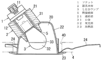
本実施形態は、図1に示すように、電球型のLEDランプ3が接続され、施工面としての天井面4に設けられた埋込穴40に埋込配設される照明器具である。以下、上下方向は図1を基準として説明する。
As shown in FIG. 1, the present embodiment is a lighting fixture to which a bulb-
詳しく説明すると、LEDランプ3は、一般的な白熱電球の口金と同様の寸法形状に形成された口金31と、口金31を介した給電により発光する発光部32と、口金31と発光部32との間に介在する放熱部33とを有する。発光部32は、例えば、複数個の発光ダイオードが、これらの発光ダイオードの光を拡散させるドーム状のカバーにより覆われたものである。また、放熱部33には、口金31から供給された交流電力を変換した直流電力により上記の発光ダイオードを点灯させる点灯回路(図示せず)が収納される。
More specifically, the
また、本実施形態は、LEDランプ3の口金31が接続されるソケット1と、ソケット1を保持する器具本体2とを備える。器具本体2は収納凹部20を有し、ソケット1は収納凹部20の底面に露出する形で保持され、LEDランプ3は発光部32を下方に向けて接続される。
In addition, the present embodiment includes a
ソケット1は、一端が電源に接続された電源線(図示せず)の他端が接続される電線接続部11と、口金31が接続される口金接続部12とを有し、接続された電源線と口金31とを互いに電気的に接続するものである。ソケット1はPPS樹脂などの絶縁材料からなる構造体に、導電材料からなる導電部が保持されてなる。電線接続部11は電源線の上記他端に設けられたプラグが挿入接続されるコネクタ状の構造であってもよいし、電源線自体が接続される速結端子のような周知の端子構造であってもよい。いずれの場合にもソケット1は周知技術で実現可能であるので詳細な図示並びに説明は省略する。
The
器具本体2は、ソケット1を囲む筒形状であってソケット1が結合する連結部21と、連結部21の下側に連結され連結部21よりも内径を大きくされて内周面においてLEDランプ3の光を反射する笠部22とを有する。ソケット1の電線接続部11は連結部21の上側に突出し、口金接続部12は連結部21の下側に露出する。また、本実施形態では、連結部21は、笠部22とは別部品で構成されている。連結部21や笠部22の材料としては合成樹脂や金属を用いることができ、特にヒートシンクとして機能する連結部21の材料としては熱伝導率が高いものが望ましい。連結部21を笠部22に結合させる手段としては、例えばねじ止めや凹凸係合といった周知の手段を適宜用いることができる。また、笠部22において、収納凹部20の内面を構成する面(すなわちLEDランプ3に向けられる面)はLEDランプ3の光を反射する。上記のような反射は、笠部22に対して研磨やめっきといった適宜の処理を施すことで実現することができる。
The
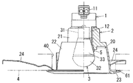
さらに、連結部21の外周面には、図2に示すように、それぞれ厚さ方向を連結部21の周方向に向けた複数個の放熱フィン211が、周方向に並べて複数枚突設されている。放熱フィン211が設けられない場合に比べて表面積が増加することで放熱性が改善される。
Furthermore, as shown in FIG. 2, a plurality of
また、器具本体2は、笠部22の下端から径方向(つまり天井面4に沿った方向)の外向きに突設された環形状であって下方から見て笠部22の外周面と埋込穴40の内周面との間の隙間を覆う鍔部23を有する。
The
さらに、器具本体2は、鍔部23の上側において一端が笠部22に連結された板ばねからなり鍔部23との間の距離を変化させる方向に弾性変形可能な複数個の取付ばね24を有する。取付ばね24は、例えば図3に示すように笠部22の周方向においてほぼ等間隔に3個設けられる。すなわち、天井面4を構成する天井材が、取付ばね24と鍔部23との間に挟まれることで、本実施形態は天井面4に対して固定される。
Further, the
ここで、本実施形態は、LEDランプ3の放熱部33を囲む筒形状であって器具本体2の連結部21の内周面に全周にわたって弾接する熱接続体5を備える。すなわち、LEDランプ3の放熱部33と器具本体2とは、熱接続体5を介して互いに熱的に接続される。また、LEDランプ3や器具本体2と熱接続体5との間での熱伝達の効率を確保するためには、熱接続体5は、LEDランプ3の放熱部33と器具本体2の連結部21との間の隙間を全周にわたって閉塞することが望ましい。さらに、本実施形態の熱接続体5は、ソケット1と連結部21の内周面との間にも介在している。
Here, this embodiment is provided with the
熱接続体5の材料としてはできるだけ熱伝導率が高く柔軟な材料が望ましく、例えば熱伝導シートや熱伝導コンパウンドの材料として用いられているものを用いることができる。より具体的には、熱接続体5の材料としては、例えば、アクリル系やシリコン系の合成樹脂に金属酸化物の粒子が混合されたものを用いることができる。
As the material of the
上記構成によれば、熱接続体5を設けない場合や、熱接続体5を連結部21の内周面の全周に弾接させない場合に比べ、LEDランプ3の放熱性が改善される。特に、図1の例のように器具本体2が埋込穴40に埋込配設される場合には、器具本体2の全体を天井面4から突出させる場合に比べ、器具本体2の周囲に空気が流れにくくなり空冷の効率が低下するから、LEDランプ3の放熱性が重要となる。また、LEDランプ3の放熱部33と器具本体2との距離を大きくすることで空冷の効率を確保しようとする場合に比べ、全体としての小型化が可能となる。
According to the said structure, the heat dissipation of the
さらに、放熱性の向上のため、放熱塗料(例えばアルミ塗料やセラミック塗料)を器具本体2やソケット1に塗布してもよい。また、器具本体2がアルミニウムからなる場合に、器具本体2にアルマイト加工を施してもよい。
Furthermore, a heat radiating paint (for example, an aluminum paint or a ceramic paint) may be applied to the appliance
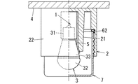
なお、図1及び図3の例ではLEDランプ3の中心軸を収納凹部20の開口面の法線(天井面4の法線)に対して傾斜させているが、図4のようにLEDランプ3の中心軸を収納凹部20の開口面の法線に平行としてもよい。図4の例は図1の例に比べ、上下方向の寸法が大きくなる代わりに、配光の均一さを確保するための笠部22の形状を比較的に単純な形状とすることができるという利点がある。本実施形態では器具本体2において連結部21が笠部22及び鍔部23とは別部品で構成されているので、図1の例と図4の例とでソケット1や熱接続体5のほか連結部21の部品も共用とすることができる。
1 and 3, the central axis of the
また、上記のように埋込穴40に埋込配設する代わりに、図5に示すように天井面4の下側に露出して固定される構造としてもよい。天井面4に対して器具本体2を固定する手段としては、例えばねじ止めなどの周知の手段を用いることができる。
Further, instead of being embedded in the embedding
または、図6に示すように天井面4に対して固定される固定部材42に対しアーム43を介して器具本体2が連結される構造としてもよい。固定部材42は例えば配線ダクトである。器具本体2はアーム43に対し例えば上下に回転可能に枢着される。
Or as shown in FIG. 6, it is good also as a structure where the instrument
または、図7に示すように天井面4から吊下げ支持される構造としてもよい。天井面4と器具本体2とを互いに連結する支持手段44としては、電源線を用いてもよいし、電源線とは別途の紐やワイヤーを用いてもよい。
Or it is good also as a structure suspended and supported from the
また、図8に示すように、連結部21と笠部22及び鍔部23とを互いに連続させて1個の部品で構成してもよい。この構成を採用すれば、部品点数が減少することで製造コストの削減が可能となる。
Moreover, as shown in FIG. 8, you may comprise the
さらに、図8の例では、鍔部23の上側に、笠部22を囲む環形状の施工面側パッキン61が配置されている。施工面側パッキン61は例えばエラストマや合成ゴムのような柔軟な材料からなる。すなわち、鍔部23と天井面4との間の隙間が施工面側パッキン61によって閉塞されることで、埋込穴40を通じた水の出入りが阻止される。
Further, in the example of FIG. 8, an annular construction surface side packing 61 that surrounds the
また、図9〜11に示すように、透光性を有する材料からなり器具本体2に結合して発光部32を覆うカバー7を設けてもよい。カバー7の材料としては例えばアクリル樹脂やポリカーボネート樹脂やガラスを用いることができる。カバー7は例えば有底円筒形状であって、カバー7の外周面に設けられたねじ山が笠部22の内周面に設けられたねじ溝に螺合することによって器具本体2に結合する。カバー7は、単純にLEDランプ3の保護や防水の目的で設けられるものであってもよいし、レンズ状の構造を有して配光に寄与するものであってもよいし、周知の色素や蛍光体を含有してLEDランプ3の光色を変換するものであってもよい。
Moreover, as shown in FIGS. 9 to 11, a
図9〜図11の例では、カバー7において収納凹部20の奥側に向けられる先端面(図9、図10では上端面、図11では右端面)と器具本体2との間には、柔軟な材料からなるカバー側パッキン62が介装されている。カバー側パッキン62の材料としては例えば合成ゴムやエラストマを用いることができる。カバー側パッキン62はカバー7の縁に沿った環形状とされており、カバー7と器具本体2との間の隙間を全周にわたって閉塞する。すなわち、カバー側パッキン62により、口金31とソケット1との接触部位への水の浸入が阻止される。
In the example of FIGS. 9 to 11, the
ところで、ソケット1への接続時にLEDランプ3が器具本体2に対して回転されると、器具本体2とLEDランプ3との間に挟まれた熱接続体5に応力がかかることで、熱接続体5に破損が発生することが考えられる。特に、LEDランプ3として、放熱部33の外周面に放熱フィン(図示せず)のような凹凸が設けられたものが用いられた場合には、上記のような破損が発生しやすくなる。そこで、図12に示すように、熱接続体5を、径方向に重ねられて互いに摺動可能な複数個の部品51,52で構成してもよい。図12の熱接続体5は、筒形状であってLEDランプ3の放熱部33の外周面に弾接する内筒51と、筒形状であって内周面が内筒51の外周面上を摺動可能であり外周面が収納凹部20の内周面に弾接する外筒52とで構成されている。この構成を採用すれば、外筒52に対して内筒51が回転することで応力が吸収されるから、熱接続体5が1個の部品からなる場合に比べて破損が発生しにくくなる。さらに、図12の例では、熱接続体5と同様の材料からなりソケット1と器具本体2との間に介在する第2熱接続体8が、熱接続体5とは別途に設けられている。
By the way, when the
1 ソケット
2 器具本体
3 LEDランプ
4 天井面(施工面)
5 熱接続体
20 収納凹部
21 連結部
31 口金
32 発光部
33 放熱部
40 埋込穴
61 施工面側パッキン
62 カバー側パッキン
1
DESCRIPTION OF
Claims (6)
前記口金が接続されるソケットと、
前記ソケットを囲む筒形状の連結部を少なくとも有する器具本体と、
前記放熱部と前記ソケットとの両方に弾接するとともに前記連結部の内周面に弾接して前記器具本体と前記LEDランプとを熱的に接続する熱接続体とを備えることを特徴とする照明器具。 A lighting fixture to which a bulb-type LED lamp having a base and a light emitting portion that emits light by power feeding through the base and a heat dissipation portion interposed between the base and the light emitting portion is connected,
A socket to which the base is connected;
An instrument body having at least a cylindrical connecting portion surrounding the socket;
An illumination comprising: a thermal connection body that elastically contacts both the heat radiating portion and the socket and that elastically connects the fixture body and the LED lamp by elastically contacting the inner peripheral surface of the coupling portion. Instruments.
前記収納凹部の内面が前記LEDランプの光を反射することを特徴とする請求項1又は請求項2記載の照明器具。 The instrument body constitutes a storage recess where the light emitting part is exposed to the inside,
The lighting apparatus according to claim 1, wherein an inner surface of the housing recess reflects light from the LED lamp.
Priority Applications (1)
| Application Number | Priority Date | Filing Date | Title |
|---|---|---|---|
| JP2011225959A JP5845461B2 (en) | 2011-10-13 | 2011-10-13 | lighting equipment |
Applications Claiming Priority (1)
| Application Number | Priority Date | Filing Date | Title |
|---|---|---|---|
| JP2011225959A JP5845461B2 (en) | 2011-10-13 | 2011-10-13 | lighting equipment |
Publications (2)
| Publication Number | Publication Date |
|---|---|
| JP2013089314A JP2013089314A (en) | 2013-05-13 |
| JP5845461B2 true JP5845461B2 (en) | 2016-01-20 |
Family
ID=48533049
Family Applications (1)
| Application Number | Title | Priority Date | Filing Date |
|---|---|---|---|
| JP2011225959A Expired - Fee Related JP5845461B2 (en) | 2011-10-13 | 2011-10-13 | lighting equipment |
Country Status (1)
| Country | Link |
|---|---|
| JP (1) | JP5845461B2 (en) |
Families Citing this family (1)
| Publication number | Priority date | Publication date | Assignee | Title |
|---|---|---|---|---|
| WO2020039584A1 (en) * | 2018-08-24 | 2020-02-27 | 有限会社ヴィンセンス | Lighting device |
Family Cites Families (3)
| Publication number | Priority date | Publication date | Assignee | Title |
|---|---|---|---|---|
| JP2010010045A (en) * | 2008-06-30 | 2010-01-14 | Toshiba Lighting & Technology Corp | Holding member and embedded apparatus |
| JP5511346B2 (en) * | 2009-12-09 | 2014-06-04 | 日本フネン株式会社 | LED lamps used in place of light bulbs for traffic lights |
| JP2011171190A (en) * | 2010-02-19 | 2011-09-01 | Toshiba Lighting & Technology Corp | Lighting system |
-
2011
- 2011-10-13 JP JP2011225959A patent/JP5845461B2/en not_active Expired - Fee Related
Also Published As
| Publication number | Publication date |
|---|---|
| JP2013089314A (en) | 2013-05-13 |
Similar Documents
| Publication | Publication Date | Title |
|---|---|---|
| CN102149962B (en) | Lighting device | |
| CN102466162B (en) | Lamp unit and lighting fixture | |
| JP5257622B2 (en) | Light bulb shaped lamp and lighting equipment | |
| US8714785B2 (en) | Cap, socket device, and luminaire | |
| JP5246402B2 (en) | Light bulb shaped lamp | |
| CN102466161B (en) | Lamp unit and lighting fixture | |
| US8408747B2 (en) | Light emitting devices having heat-dissipating surface | |
| MX2011005992A (en) | Radially-shaped heat dissipating apparatus, and bulb-shaped led lighting apparatus using same. | |
| CN103732977B (en) | Lamp and ligthing paraphernalia | |
| CN103189681B (en) | lamp | |
| CN101936471A (en) | Lamps and Lighting Fixtures | |
| CN102308143A (en) | Lamp and illumination apparatus | |
| JP5499475B2 (en) | Lamp device and lighting device | |
| US20140204572A1 (en) | System for Adapting an Existing Florescent Light Fixture with an LED Luminaire | |
| JP4671064B2 (en) | lighting equipment | |
| KR20100118136A (en) | Semiconductor solid state lighting fixtures and their lighting methods | |
| KR20100081558A (en) | An incandescence lamp alternation change led lamp | |
| JP2011065795A (en) | Heat radiation adapter, lamp device, and lighting fixture | |
| TWI471502B (en) | Heat sink apparatus for solid state lights | |
| JP6167744B2 (en) | lamp | |
| CN202598185U (en) | Lamp device and illumination device | |
| JP2010073569A (en) | Lamp device and illumination fixture | |
| JP5845461B2 (en) | lighting equipment | |
| TWI577926B (en) | Lamp | |
| JP5674065B2 (en) | Light bulb shaped lamp |
Legal Events
| Date | Code | Title | Description |
|---|---|---|---|
| A621 | Written request for application examination |
Free format text: JAPANESE INTERMEDIATE CODE: A621 Effective date: 20140626 |
|
| A711 | Notification of change in applicant |
Free format text: JAPANESE INTERMEDIATE CODE: A711 Effective date: 20141008 |
|
| A131 | Notification of reasons for refusal |
Free format text: JAPANESE INTERMEDIATE CODE: A131 Effective date: 20150317 |
|
| A977 | Report on retrieval |
Free format text: JAPANESE INTERMEDIATE CODE: A971007 Effective date: 20150318 |
|
| A521 | Written amendment |
Free format text: JAPANESE INTERMEDIATE CODE: A523 Effective date: 20150518 |
|
| TRDD | Decision of grant or rejection written | ||
| A01 | Written decision to grant a patent or to grant a registration (utility model) |
Free format text: JAPANESE INTERMEDIATE CODE: A01 Effective date: 20150609 |
|
| A61 | First payment of annual fees (during grant procedure) |
Free format text: JAPANESE INTERMEDIATE CODE: A61 Effective date: 20150703 |
|
| R151 | Written notification of patent or utility model registration |
Ref document number: 5845461 Country of ref document: JP Free format text: JAPANESE INTERMEDIATE CODE: R151 |
|
| LAPS | Cancellation because of no payment of annual fees |


