JP5840552B2 - Electric motor - Google Patents
Electric motor Download PDFInfo
- Publication number
- JP5840552B2 JP5840552B2 JP2012079946A JP2012079946A JP5840552B2 JP 5840552 B2 JP5840552 B2 JP 5840552B2 JP 2012079946 A JP2012079946 A JP 2012079946A JP 2012079946 A JP2012079946 A JP 2012079946A JP 5840552 B2 JP5840552 B2 JP 5840552B2
- Authority
- JP
- Japan
- Prior art keywords
- holder
- space
- bracket
- seal
- brush
- Prior art date
- Legal status (The legal status is an assumption and is not a legal conclusion. Google has not performed a legal analysis and makes no representation as to the accuracy of the status listed.)
- Expired - Fee Related
Links
- 230000029058 respiratory gaseous exchange Effects 0.000 claims description 38
- 238000005192 partition Methods 0.000 claims description 33
- 238000007789 sealing Methods 0.000 claims description 3
- 230000002093 peripheral effect Effects 0.000 description 21
- 238000009413 insulation Methods 0.000 description 6
- 239000000843 powder Substances 0.000 description 5
- 238000005299 abrasion Methods 0.000 description 4
- 238000009423 ventilation Methods 0.000 description 4
- 210000000078 claw Anatomy 0.000 description 3
- 239000000463 material Substances 0.000 description 3
- 239000011347 resin Substances 0.000 description 3
- 229920005989 resin Polymers 0.000 description 3
- 230000004308 accommodation Effects 0.000 description 2
- 239000000126 substance Substances 0.000 description 2
- XAGFODPZIPBFFR-UHFFFAOYSA-N aluminium Chemical compound [Al] XAGFODPZIPBFFR-UHFFFAOYSA-N 0.000 description 1
- 229910052782 aluminium Inorganic materials 0.000 description 1
- 230000002542 deteriorative effect Effects 0.000 description 1
- 235000013312 flour Nutrition 0.000 description 1
- 235000013305 food Nutrition 0.000 description 1
- 230000005484 gravity Effects 0.000 description 1
- WABPQHHGFIMREM-UHFFFAOYSA-N lead(0) Chemical compound [Pb] WABPQHHGFIMREM-UHFFFAOYSA-N 0.000 description 1
- 239000000696 magnetic material Substances 0.000 description 1
- 238000000465 moulding Methods 0.000 description 1
- 230000000149 penetrating effect Effects 0.000 description 1
Images


Landscapes
- Motor Or Generator Frames (AREA)
Description
この発明は、外部との間で通気が可能な電動モータに関するものである。 The present invention relates to an electric motor that can ventilate outside.
電気部品には、該電気部品に設けられた呼吸孔を介して、電気部品の内部と外部との間で通気することができる構造を採用したものがある。
例えば、特許文献1には、内部に制御基板を備えたコントローラのケースに、ケーブル接続用の防水コネクタ部を設け、このコネクタ部にケース内と連通する呼吸孔を設け、コネクタ部にケーブルを接続すると、ケーブル内に形成された空気通路がコネクタ部の呼吸孔を介してケース内に連通し、ケーブル及び呼吸孔を介してケースの内部が外部に連通するように構成されている。
Some electrical components employ a structure that allows ventilation between the inside and the outside of the electrical component through a breathing hole provided in the electrical component.
For example, in
しかしながら、特許文献1に記載された構造では、呼吸孔がコネクタ部に直線状に形成されているため、雨水等がコネクタ部の呼吸孔を容易に通過してケース内に侵入し易く、ケース内に収容されている部品(特許文献1においては制御基板)が被水し易いという課題がある。
また、ケース内やコネクタ内に導電性の異物があった場合に、この異物が通気によって飛散し、呼吸孔からコネクタ内等に侵入して、電気的導通部位の信頼性や絶縁性を低下させる虞もある。
However, in the structure described in
In addition, when there is conductive foreign matter in the case or connector, the foreign matter is scattered by ventilation and enters the connector etc. from the breathing hole, reducing the reliability and insulation of the electrical conduction part. There is also a fear.
そこで、この発明は、モータ内部に雨水等が侵入し難くするとともに、モータ内部に導電性異物が存在した場合にその異物が飛散して不用意に電気的導通部位に至り難くすることができる呼吸可能な電動モータを提供するものである。 Therefore, the present invention makes it difficult for rainwater or the like to enter the motor, and when there is a conductive foreign substance inside the motor, the foreign substance is scattered and cannot easily reach the electrical conduction site. A possible electric motor is provided.
この発明に係る電動モータでは、上記課題を解決するために以下の手段を採用した。
請求項1に係る発明は、
整流子を有するロータと、
内部に前記ロータを回転可能に収容するケーシング本体と、
前記整流子に摺接して電流を流すブラシを保持するブラシ格納部と、中央に前記ロータの回転軸における前記整流子よりも先端側を挿通させる貫通孔が設けられた隔壁部と、外周部に配置されたコネクタ部とが一体的に設けられたホルダと、
前記ホルダを間に挟んで前記ケーシング本体に連結されるブラケットと、
前記ホルダと前記ブラケットとの間をシールするシール部材と、
を備える電動モータにおいて、
前記シール部材は、前記ホルダ及び前記ブラケットとに密接してシールするシール部と、該シール部よりも径方向内側に配置され前記ホルダの前記隔壁部との間に空間を形成する非シール部と、を備え、
前記ホルダには呼吸孔が設けられ、前記呼吸孔の一端は、前記コネクタ部内に開口して外部に連通し、前記呼吸孔の他端は、前記隔壁部において前記ブラケットに対向する面に開口し、且つ前記他端の開口は、前記シール部材の前記非シール部に対向して配置されており、
前記呼吸孔の前記他端の開口は、前記シール部材の非シール部と前記ホルダの前記隔壁部との間に形成された第1の空間と、前記第1の空間よりも径方向内側であって前記隔壁部と前記ブラケットとの間に形成された第2の空間と、前記第1の空間と前記第2の空間とを連通するとともに、前記ブラケットと前記ホルダとの間でラビリンス状に形成された連通路と、前記隔壁部の前記貫通孔と前記ロータの前記回転軸との間に形成され前記第2の空間に連通する第3の空間とを介して、前記ケーシング本体の内部に連通していることを特徴とする電動モータである。
The electric motor according to the present invention employs the following means in order to solve the above problems.
The invention according to
A rotor having a commutator;
A casing main body that rotatably accommodates the rotor;
A brush housing portion that holds a brush that slidably contacts the commutator and allows current to flow; a partition wall portion provided with a through-hole through which the tip side of the commutator is inserted in the rotation shaft of the rotor; A holder integrally provided with the arranged connector part;
A bracket connected to the casing body with the holder interposed therebetween,
A seal member for sealing between the holder and the bracket;
In an electric motor comprising:
The seal member includes a seal portion that seals closely to the holder and the bracket, and a non-seal portion that is disposed radially inward of the seal portion and forms a space between the partition portion of the holder. With
The holder is provided with a breathing hole, one end of the breathing hole is opened in the connector portion and communicated with the outside, and the other end of the breathing hole is opened on a surface of the partition wall facing the bracket. And the opening at the other end is disposed to face the non-seal portion of the seal member,
The opening at the other end of the breathing hole is a first space formed between the non-seal portion of the seal member and the partition portion of the holder, and is radially inward of the first space. The second space formed between the partition wall portion and the bracket communicates with the first space and the second space, and is formed in a labyrinth shape between the bracket and the holder. And communicating with the inside of the casing body through a communicating path and a third space formed between the through hole of the partition wall and the rotating shaft of the rotor and communicating with the second space. It is the electric motor characterized by having carried out.
このように構成すると、電動モータの外部とケーシング本体内とを、呼吸孔と第1の空間と連通路と第2の空間と第3の空間を介して連通することができ、ケーシング本体内の圧力を外部と等圧にすることができる。
また、コネクタ部から雨水等がケーシング本体内に侵入するには、呼吸孔と第1の空間と連通路と第2の空間と第3の空間からなる距離が長くて複雑な経路を通らなければならないので、ケーシング本体内に雨水等が侵入し難くすることができる。その結果、ケーシング本体内が被水し難くなる。
また、ケーシング本体内に導電性の異物が存在し、通気によって不用意に飛散したとしても、呼吸孔と第1の空間と連通路と第2の空間と第3の空間からなる距離が長くて複雑な経路を通らなければならないので、コネクタ部内等に導電性の異物が侵入し難くすることができる。その結果、コネクタ部の電気的導通部位の信頼性や絶縁性が低下するのを防止することができる。
If comprised in this way, the exterior of an electric motor and the inside of a casing main body can be connected via a breathing hole, a 1st space, a communicating path, a 2nd space, and a 3rd space, The pressure can be made equal to the external pressure.
Further, in order for rainwater or the like to enter the casing body from the connector portion, the distance consisting of the breathing hole, the first space, the communication path, the second space, and the third space must be long and not pass through a complicated route. Therefore, rainwater or the like can hardly enter the casing body. As a result, it becomes difficult for the inside of the casing body to get wet.
Even if conductive foreign matter exists in the casing body and is inadvertently scattered by ventilation, the distance between the breathing hole, the first space, the communication path, the second space, and the third space is long. Since it must pass through a complicated path, it is possible to make it difficult for a conductive foreign object to enter the connector portion or the like. As a result, it is possible to prevent the reliability and insulating properties of the electrically conductive portion of the connector portion from being lowered.
請求項2に係る発明は、請求項1に記載の発明において、前記呼吸孔の前記他端の開口は、前記ブラシから離間した位置に設けられていることを特徴とする。
このように構成すると、ブラシの摩耗により生じる導電性の異物(摩耗粉)がコネクタ部に侵入し難くすることができる。
According to a second aspect of the present invention, in the first aspect of the present invention, the opening at the other end of the breathing hole is provided at a position separated from the brush.
If comprised in this way, the electroconductive foreign material (wear powder | flour) which arises by abrasion of a brush can make it difficult to penetrate | invade a connector part.
請求項1に係る発明によれば、ケーシング本体内が被水し難くなるとともに、コネクタ部内の絶縁性が低下するのを防止することができる。
請求項2に係る発明によれば、ブラシの摩耗により生じる導電性の異物(摩耗粉)がコネクタ部に侵入し難くすることができ、コネクタ部内の絶縁性が低下するのを防止することができる。
According to the first aspect of the present invention, it is difficult for the inside of the casing body to get wet, and it is possible to prevent the insulation in the connector portion from being lowered.
According to the second aspect of the present invention, it is possible to make it difficult for conductive foreign matter (abrasion powder) generated by the abrasion of the brush to enter the connector portion, and to prevent the insulation in the connector portion from being lowered. .
以下、この発明に係る電動モータの実施形態を図1から図13の図面を参照して説明する。
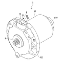
図1は電動モータ1の外観斜視図であり、図2は電動モータ1の縦断面図であり、図3は要部を拡大して示す縦断面図である。
電動モータ1は、ケーシング2と、ケーシング2に回転可能に支持されたロータ(アーマチュア)3と、ケーシング2に固定され後述するブラシ31を保持するホルダユニット4と、を備えている。なお、以下の説明では、ロータ3の軸方向をモータ軸方向(以下、軸方向と略す)といい、ケーシング2及びロータ3の径方向をモータ径方向(以下、径方向と略す)というものとする。
Embodiments of an electric motor according to the present invention will be described below with reference to the drawings of FIGS.
FIG. 1 is an external perspective view of the
The
ケーシング2は、アルミニウム材からなる略円板状のブラケット5と、後端を閉塞させ前端を開口させた磁性材からなる略円筒状のケーシング本体6とから構成され、ブラケット5とケーシング本体6との間にホルダユニット4を挟装させて、ケーシング本体6の前端をブラケット5にねじ(図示略)で締結することにより連結されている。ケーシング本体6の磁石収容部60の内周面には、界磁用の二つの永久磁石7が径方向に対向して固定されており、それによりステータが構成されている。
ブラケット5の中央には、ロータ3の回転軸(出力軸)20を挿通させる孔部8が形成されている。また、ブラケット5においてホルダユニット4に対向する面には、孔部8と同芯上に、内側から、軸受取付凹部11と、環状のインロー溝12と、環状のシール部材収容凹部13と、ホルダ最外側収容凹部14と、が設けられており、インロー溝12とシール部材収容凹部13との間は非シール部受け面15となっている。また、図1に示すように、ブラケット5の外周部の上側には径方向外側に開口する切り欠き部16が形成されている。
The
In the center of the
ロータ3は、回転軸20と、回転軸20に固定されたロータコア21と、ロータコア21のスロットに巻装されたコイル23とを備えている。回転軸20は、ブラケット5の軸受取付凹部11に固定された軸受9と、ケーシング本体6の後端に固定された軸受10によって回転可能に支持されており、回転軸20の先端部がブラケット5の孔部8を介して外部に突出している。回転軸20の先端部にはギヤ部が一体的に設けられ、図示しない被駆動体の減速機構等と連結されるようになっている。ロータコア21は、ケーシング本体6に固定された永久磁石7と対向するように配置されている。
The rotor 3 includes a rotating
ケーシング2の内部に位置するロータ3前端側には、コイル23に流れる電流の方向を切り替える整流子24が配置されている。整流子24は、周方向に配列された複数のセグメント25を備え、各セグメント25にそれぞれのコイル23が接続されている。
A
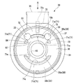
図4は、ホルダユニット4を軸方向の後端側(ケーシング本体6側)から見た背面図であり、ロータ3のセグメント25を仮想線で示している。
ホルダユニット4は、樹脂材料からなるホルダ30と、ホルダ30に支持された一対のブラシ31と、ブラシ31を径方向内側に付勢する一対のスプリング32と、ブラシ31に外部から給電する一対のターミナル33と、を備えている。ブラシ31は、整流子24のセグメント25に摺接して整流子24に電流を流す部材であり、ターミナル33はブラシ31に外部から給電する部材である。
FIG. 4 is a rear view of the
The
ホルダ30は、正面視略円形をなす本体部34と、本体部34と一体に形成され本体部34の上部から上方に延出する筒状のコネクタ部35と、本体部34の前面側(ブラケット5側)に固定された蓋体36(図2、図5参照)と、を備えている。
本体部34の周壁部37は、図2に示すように、ブラケット5のホルダ最外側収容凹部14に収容され、コネクタ部35は、図1に示すように、ブラケット5の切り欠き部16に収容されている。
The
As shown in FIG. 2, the
本体部34の後面側(ケーシング本体6と対向する側)には、周壁部37の内側に、ケーシング本体6に対するインロー部39が、ケーシング本体6に接近する方向へ突出形成されている。インロー部39は周壁部37よりも小径の円環状をなし、周壁部37と同芯状に設けられている。このインロー部39は、ケーシング本体6の開口側に形成された係合凹部61に嵌入され、これによりホルダ30とケーシング本体6との芯出しが行われる。なお、係合凹部61の内径は磁石収容部60の内径よりも大径にされている。また、本体部34のインロー部39とケーシング本体6の開口周壁との間には、ホルダ30とケーシング本体6との間をシールする環状のシール部材62が取り付けられている。
On the rear surface side of the main body portion 34 (side facing the casing main body 6), an
本体部34のインロー部39の内側には隔壁部38が形成されており、隔壁部38の中央には、ロータ3の回転軸20を挿通させる貫通孔45が、インロー部39と同芯上に形成されている。
本体部34の後面側であってインロー部39の内側には、貫通孔45を間に挟んでその両側に一つずつブラシ格納部40が隔壁部38と一体的に設けられている。ブラシ格納部40は、コネクタ部35から周方向に90度離間して配置されている。ブラシ格納部40は、上壁部(仮保持部)41と一対の側壁部42とにより断面略コ字形に形成されており、径方向の両側と本体部34の前面側(ロータ3とは反対側)を開口させている。
A
On the rear surface side of the
また、本体部34の後面側であってインロー部39の内側には、ブラシ格納部40よりもコネクタ部35から離間する側に、スプリング32を支持するピン43が、各ブラシ格納部40の近傍にそれぞれ一つずつ隔壁部38から起立して一体的に設けられている。
In addition, on the rear surface side of the
ブラシ格納部40の上壁部41には、この上壁部41の径方向内側の端部に開口するU字形の溝部44が形成されている。
また、隔壁部38には、各ピン43の近傍であってブラシ格納部40から周方向に離間する側に、係止爪48が一体的に突設されている。係止爪48は、上端を径方向外側に屈曲させた逆L字形をなしている。
A
In addition, a locking
各ブラシ格納部40にはそれぞれ、直方体形状をなすブラシ31が収容されており、ブラシ格納部40の前面側の開口は、一対のブラシ格納部40にそれぞれブラシを挿入した後、図5に示すように、本体部34の前面側にスナップフィットによって固定される樹脂製の蓋体36によって塞がれ、これによりブラシ31はブラシ格納部40から前面側に脱落しないようにされている。
Each
スプリング32は、コイル部50と、コイル部50の一端に連なる第1端部51と、コイル部50の他端に連なる第2端部52とから構成されている。スプリング32は、ピン43をコイル部50に挿入することによって本体部34に取り付けられており、第1端部51が係止爪48に係止され、第2端部52がブラシ格納部40内に挿入されてブラシ31の後端に係止されている。そして、このスプリング32によってブラシ31は径方向内方へと押圧され、この付勢力によりブラシ31は整流子24のセグメント25に押し付けられるようになっている。
なお、ブラシ格納部40の二つの側壁部42のうちピン43に対向して配置された側壁部42には、この側壁部42の径方向外側の端部に開口し径方向内側に向かって延びる溝(図示せず)が形成されている。スプリング32の第2端部52はこの溝を挿通することによって、ブラシ格納部40の内部に挿入されている。
The
Of the two
ブラシ31の径方向外側の上面にはピグテイル59の一端が接合されており、ピグテイル59はブラシ格納部40の上壁部41の溝部44を挿通してブラシ格納部40の外に引き出され、このピグテイル59の他端がターミナル33に接合されている。
ターミナル33はインサート成形によりホルダ30と一体的に形成にされており、ターミナルの先端がコネクタ部35の内部に露出している。
One end of the
The terminal 33 is formed integrally with the
図5はホルダ30を前面側(ブラケット5と対向する側)から見た正面図であり、本体部34の前面側には、周壁部37の内側に周壁部37よりも小径で周壁部37と同芯状の円環状をなすシール筒部70がブラケット5に接近する方向へ突出形成されている。このシール筒部70の内径は後面側のインロー部39の内径と略同一径にされており、したがって、シール筒部70の内側は前述した隔壁部38となっている。このシール筒部70は、ブラケット5のシール部材収容凹部13に挿入されている。
FIG. 5 is a front view of the
さらに、本体部34の前面側であってシール筒部70の内側には、ブラケット5に対するインロー部71が、ブラケット5に接近する方向に突出形成されている。
この図に示すように、インロー部71は、シール筒部70と同芯上に形成された円弧片であって、シール筒部70の内径より小さい同一外径の四つの円弧片71a〜71dから構成されている。第1の円弧片71aはコネクタ部35に対向する位置に配置されており、第1の円弧片71aから周方向両側に離間して第2の円弧片71bと第3の円弧片71cが配置され、第1の円弧片71aの周方向反対側に第4の円弧片71dが配置されている。そして、第2の円弧片71bと第4の円弧片71dの間、及び、第3の円弧片71cと第4の円弧片71dの間に、それぞれブラシ格納部40の前面側の開口が位置している。このインロー部71の内周面側には径方向内側に向けて複数のリブ71eが設けられ、各リブ71eの内径側を結ぶ線はブラケット5のインロー溝12と同芯状の円となるよう設定されている。このリブ71eが、ブラケット5のインロー溝12に嵌入され、これによりホルダ30とブラケット5との芯出しが行われる。
Further, an
As shown in this figure, the
また、第1の円弧片71aと第2の円弧片71bの間、及び、第1の円弧片71aと第3の円弧片71cの間には、隔壁部38を貫通する孔72が形成されている。この孔72は、その深さの中間部において、樹脂製の本体部34に埋設されているターミナル33によって塞がれている。
In addition, a
隔壁部38において、第4の円弧片71dの外側に位置する下側隔壁部38bは、第1の円弧片71aと第2の円弧片71bと第3の円弧片71cの外側に位置する上側隔壁部38aよりも後面側(ロータ3の方向)に凹んでいる。この凹んでいる下側隔壁部38bとブラシ格納部40の前面側の開口部分に、前述した蓋体36がスナップフィットによって固定され、蓋体36の表面と上側隔壁部38aの表面とが面一になるようになっている。なお、回転軸20を挿通させる貫通孔45は、隔壁部38においてインロー部71の内側に位置する中央隔壁部38cの中央に形成されている。
In the
また、ホルダ30には呼吸孔72が設けられている。図6に示すように、呼吸孔72の一端72aは、コネクタ部35の底部35aに開口して外部に連通しており、図5に示すように、呼吸孔72の他端72bは上側隔壁部38aの前面(ブラケット5に対向する面)であってシール筒部70の径方向内側において上側隔壁部38aの径方向最外縁に開口している。つまり、呼吸孔72の他端72bは、ブラシ31から離間して、ホルダ30の本体部34の外周に近い位置に開口している。
The
図2に示すように、ブラケット5とホルダ30との間にはシール部材73が取り付けられている。図7はシール部材73の斜視図であり、シール部材73は、ブラケット5のシール部材収容凹部13に収容される円環状のシール部74と、ブラケット5の非シール部受け面15に当接する円環状の非シール部75とを有し、シール部74の内周部と非シール部75の外周部とが段差部76とによって接続されて構成されている。
As shown in FIG. 2, a
シール部74は、ブラケット5に当接する面及びホルダ30に当接する面のいずれも平坦面に形成されている。一方、非シール部75は、ブラケット5に当接する面は平坦面に形成されているが、ホルダ30に当接する面には、周方向に一周する突条76と、径方向に延びる複数の突条77とが設けられている。
シール部74は、ブラケット5のシール部材収容凹部13に収容され、シール部材収容凹部13に挿入されたホルダ30のシール筒部70の先端に押圧されることにより、シール部材収容凹部13の底面とシール筒部70の先端のシール面70aに密着する。これにより、ブラケット5とホルダ30との間がシールされる。
The
The
一方、非シール部75は、前記平坦面をブラケット5の非シール部受け面15に当接させ、突条76,77をホルダ30の上側隔壁部38a及び蓋体36の表面に当接させて、ブラケット5とホルダ30との間に挟装される。これにより、蓋体36は本体部34に押し付けられた状態で保持される。また、突条76,77が設けられていることにより、図3に示すように、非シール部75とホルダ30の上側隔壁部38a及び蓋体36の表面との間に第1の空間81が形成される。
On the other hand, the
また、図3に示すように、ホルダ30の本体部34においてインロー部71よりも内側に位置する中央隔壁部38cは、ブラケット5から軸方向に離間して配置されており、中央隔壁部38cとインロー溝12よりも径方向内側のブラケット5との間に第2の空間82が形成されている。
Further, as shown in FIG. 3, the central
また、図3に示すように、ホルダ30の本体部34の貫通孔45の内周面とロータ3の回転軸20の外周面との間には第3の空間83が形成されている。
さらに、図5に示すように、ホルダ30の本体部34において、インロー部71の内周側に設けられた複数のリブ71eとインロー溝12との間に形成される空間を介して連通路84が形成されている。また、インロー部71の第1の円弧片71aと第2の円弧片71bの間、及び、第1の円弧片71aと第3の円弧片71cの間も連通路84としての機能を有する。したがって、連通路84は、呼吸孔72の他端72bとの間でその通気経路がラビリンス状となるよう形成されている。
As shown in FIG. 3, a
Further, as shown in FIG. 5, in the
これら第1の空間81と連通孔84と第2の空間82と第3の空間83とを介して、呼吸孔72はケーシング本体6内に連通されている。詳述すると、呼吸孔72の他端72bは、ホルダ30の本体部34における上側隔壁部38aの前面に開口しているので、この他端72bは第1の空間81に連通する。第1の空間81は、他端72bからラビリンス状に形成された連通路84を介して第2の空間82に連通し、第2の空間82は第3の空間83に連通し、第3の空間83はケーシング本体6の内部に連通している。したがって、呼吸孔72は、第1の空間81と連通孔84と第2の空間82と第3の空間83とからなる距離の長い曲がりくねった複雑な経路を介して、ケーシング本体6内に連通することとなる。
The
ホルダ30のコネクタ部35には図示しない雄コネクタが嵌入され、前記雄コネクタに接続された図示しないハーネスの導線がターミナル33に接続され、前記ハーネス内部に形成された図示しない通路とホルダ30の呼吸孔72とが接続される。これにより、ハーネスを介して電動モータ1のケーシング本体6内と外部とを連通させることができ、呼吸することができるようになっている。
A male connector (not shown) is inserted into the
しかしながら、前述したように、呼吸孔72は、第1の空間81と連通孔84と第2の空間82と第3の空間83とからなる距離の長い曲がりくねった複雑な経路を介して、ケーシング本体6内に連通しているので、コネクタ部35からケーシング本体6内に雨水等を侵入し難くすることができる。その結果、ケーシング本体6内を被水し難くすることができる。
However, as described above, the
また、ブラシ31の摩耗により生じた摩耗粉などの導電性の異物がケーシング本体6からコネクタ部35に漏出する場合も、距離の長い曲がりくねった複雑な前記経路を通らなければならないので、前記導電性異物がコネクタ部35に流出し難くなり、コネクタ部35内の電気的導通性や絶縁性が低下するのを阻止することができる。
特に、呼吸孔72の他端72bが、ブラシ31から離間した位置に開口しているので、ブラシの摩耗により生じる導電性の異物(摩耗粉)がコネクタ部に侵入し難くすることができる。
Further, even when conductive foreign matter such as abrasion powder generated by the wear of the
In particular, since the
一方、図2に戻って、ケーシング本体6の後壁部63にも呼吸孔64が形成されている。これは電動モータ1全体を密閉空間に収容した場合に、前記密閉空間とケーシング本体6内とを連通させるためであり、このようにしておくと、電動モータ1内と前記密閉空間内を等圧にすることができ、その結果、前記密閉空間内を外部と等圧にすることができる。
On the other hand, returning to FIG. 2, a
また、ケーシング本体6の内部において、ホルダ30の本体部34とケーシング本体6との間には、フード部材90が取り付けられている。図8はフード部材90の斜視図、図9(A)はフード部材90を後部側から見た正面図、図9(B)は同右側面図、図9(C)は図9(A)のB−B矢視断面図である。
A
フード部材90は、軸方向の両端を開口させた略円筒状をなしており、ケーシング本体6における磁石収容部60の前端側に挿入される後筒部91と、ホルダ30における本体部34のインロー部39の内側に挿入される前筒部92と、後筒部91と前筒部92との間に形成され径方向外側に突出するリング状の鍔部93と、後筒部91の後端から径方向内側に向かって延びるリング状の突起部94と、後筒部91の外周面に周方向所定間隔に設けられ径方向外側に突出する嵌合突起部95と、を備えて構成されている。
The
このフード部材90は、後筒部91の嵌合突起部95をケーシング本体6の磁石収容部60に嵌合させることによりケーシング本体6に固定されており、前筒部92が、ホルダ30における本体部34のインロー部39の内側に挿入され、鍔部93がインロー部39の端面に突き当たっている。なお、前筒部92の外周面とインロー部39の内周面との間には径方向に若干の隙間が形成されている。そして、この取付状態において、フード部材90の突起部94が永久磁石7の端面と対向するように配置されている。
The
このように径方向内側に向かって延びるリング状の突起部94を備えたフード部材90が、ケーシング本体6の磁石収容部60の開口端部に設置されていることにより、ブラシ31の摩耗により生じた摩耗粉などの導電性の異物が、フード部材90よりも後方側(永久磁石7側)に侵入し難くすることができ、これによりケーシング本体6の絶縁性が低下するのを抑制することができる。
The
なお、電動モータ1の取付姿勢が、例えばコネクタ部35が鉛直方向の上方に位置するように決まっている場合には、前述したフード部材90を取り付ける代わりに、図10に示すように、ホルダ30の本体部34のインロー部39において鉛直方向の下方に位置する側の一部、すなわちコネクタ部35から周方向180度離間する側の一部を、ケーシング本体6側に延長させてフード部46を部分的に形成してもよい。前記導電性の異物は重力により鉛直下方に集まり易いので、集まり易い側にフード部46を形成することによって、前記導電性異物が、ケーシング本体6の後方側(永久磁石7側)に侵入し難くすることができ、これによりケーシング本体6の絶縁性が低下するのを抑制することができる。
If the mounting posture of the
また、図11に示すように、ホルダユニット4のコネクタ部35と、ケーシング本体6の呼吸孔64とを、周方向同一位置に配置する場合には、ケーシング本体6の開口側の外周鍔部65であって呼吸孔64と周方向同一位置に、径方向外側に突出する突出片66を設けておくのが好ましい。
As shown in FIG. 11, when the
このように突出片66を設けておくと、図12に示すように、ブラケット5とホルダユニット4及びロータ3とを組み立てた後に、ロータ3の上からケーシング本体6を被せてていき、ケーシング本体6とブラケット5とをねじ部材67によって連結する際に、ブラケット5の切り欠き部16に収納されたコネクタ部35の上に、ケーシング本体6の突出片66を配置すれば、コネクタ部35とケーシング本体6の呼吸孔64とを周方向同一位置に配置することが容易にできる。したがって、ケーシング本体6の呼吸孔64を、コネクタ部35から周方向に180度反対側に配置してしまう組み立てミスの発生を確実に防止することができる。
If the projecting
また、前記組み立てミスをより確実に防止することができるように、図13に示すように、コネクタ部35においてケーシング本体6側の外面に係合ピン47を突設しておき、ケーシング本体6に設けた前記突出片66に係合凹部68を設けておいて、係合ピン47を係合凹部68に係合するようにしてもよい。係合ピン47と係合凹部68とが係合しない位置でケーシング本体6とホルダ30とを重ねると、ケーシング本体6の外周鍔部65がホルダ30の係合ピン47に乗り上げてしまうため、ケーシング本体6の外周鍔部65をブラケット5の端面に接触させることができなくなるので、その時点でケーシング本体6とホルダ30との周方向相対位置が間違っていることを認識することができる。その結果、組み立てミスの発生をより確実に防止することができる。
Further, as shown in FIG. 13, an
なお、本発明は、前述した実施形態に限るものではない。
例えば、第1の空間81、第2の空間、第3の空間、連通路の形状等は、前述した実施形態の形状に限るものではなく、本発明の要旨を逸脱しない範囲で適宜変更可能である。
The present invention is not limited to the embodiment described above.
For example, the shape of the
1 電動モータ
3 ロータ
5 ブラケット
6 ケーシング本体
20 回転軸
24 整流子
30 ホルダ
31 ブラシ
35 コネクタ部
38,38a,38b,38c 隔壁部
45 貫通孔
70 シール筒部
70a シール面
72 呼吸孔
72a 一端
72b 他端
73 シール部材
74 シール部
75 非シール部
81 第1の空間
82 第2の空間
83 第3の空間
84 連通路
DESCRIPTION OF
Claims (2)
内部に前記ロータを回転可能に収容するケーシング本体と、
前記整流子に摺接して電流を流すブラシを保持するブラシ格納部と、中央に前記ロータの回転軸における前記整流子よりも先端側を挿通させる貫通孔が設けられた隔壁部と、外周部に配置されたコネクタ部とが一体的に設けられたホルダと、
前記ホルダを間に挟んで前記ケーシング本体に連結されるブラケットと、
前記ホルダと前記ブラケットとの間をシールするシール部材と、
を備える電動モータにおいて、
前記シール部材は、前記ホルダ及び前記ブラケットとに密接してシールするシール部と、該シール部よりも径方向内側に配置され前記ホルダの前記隔壁部との間に空間を形成する非シール部と、を備え、
前記ホルダには呼吸孔が設けられ、前記呼吸孔の一端は、前記コネクタ部内に開口して外部に連通し、前記呼吸孔の他端は、前記隔壁部において前記ブラケットに対向する面に開口し、且つ前記他端の開口は、前記シール部材の前記非シール部に対向して配置されており、
前記呼吸孔の前記他端の開口は、前記シール部材の非シール部と前記ホルダの前記隔壁部との間に形成された第1の空間と、前記第1の空間よりも径方向内側であって前記隔壁部と前記ブラケットとの間に形成された第2の空間と、前記第1の空間と前記第2の空間とを連通するとともに、前記ブラケットと前記ホルダとの間でラビリンス状に形成された連通路と、前記隔壁部の前記貫通孔と前記ロータの前記回転軸との間に形成され前記第2の空間に連通する第3の空間とを介して、前記ケーシング本体の内部に連通していることを特徴とする電動モータ。 A rotor having a commutator;
A casing main body that rotatably accommodates the rotor;
A brush housing portion that holds a brush that slidably contacts the commutator and allows current to flow; a partition wall portion provided with a through-hole through which the tip side of the commutator is inserted in the rotation shaft of the rotor; A holder integrally provided with the arranged connector part;
A bracket connected to the casing body with the holder interposed therebetween,
A seal member for sealing between the holder and the bracket;
In an electric motor comprising:
The seal member includes a seal portion that seals closely to the holder and the bracket, and a non-seal portion that is disposed radially inward of the seal portion and forms a space between the partition portion of the holder. With
The holder is provided with a breathing hole, one end of the breathing hole is opened in the connector portion and communicated with the outside, and the other end of the breathing hole is opened on a surface of the partition wall facing the bracket. And the opening at the other end is disposed to face the non-seal portion of the seal member,
The opening at the other end of the breathing hole is a first space formed between the non-seal portion of the seal member and the partition portion of the holder, and is radially inward of the first space. The second space formed between the partition wall portion and the bracket communicates with the first space and the second space, and is formed in a labyrinth shape between the bracket and the holder. And communicating with the inside of the casing body through a communicating path and a third space formed between the through hole of the partition wall and the rotating shaft of the rotor and communicating with the second space. An electric motor characterized by that.
Priority Applications (1)
| Application Number | Priority Date | Filing Date | Title |
|---|---|---|---|
| JP2012079946A JP5840552B2 (en) | 2012-03-30 | 2012-03-30 | Electric motor |
Applications Claiming Priority (1)
| Application Number | Priority Date | Filing Date | Title |
|---|---|---|---|
| JP2012079946A JP5840552B2 (en) | 2012-03-30 | 2012-03-30 | Electric motor |
Publications (2)
| Publication Number | Publication Date |
|---|---|
| JP2013211978A JP2013211978A (en) | 2013-10-10 |
| JP5840552B2 true JP5840552B2 (en) | 2016-01-06 |
Family
ID=49529347
Family Applications (1)
| Application Number | Title | Priority Date | Filing Date |
|---|---|---|---|
| JP2012079946A Expired - Fee Related JP5840552B2 (en) | 2012-03-30 | 2012-03-30 | Electric motor |
Country Status (1)
| Country | Link |
|---|---|
| JP (1) | JP5840552B2 (en) |
Families Citing this family (12)
| Publication number | Priority date | Publication date | Assignee | Title |
|---|---|---|---|---|
| JP6277425B2 (en) | 2014-11-28 | 2018-02-14 | 日本電産株式会社 | motor |
| US20170147925A1 (en) | 2015-11-23 | 2017-05-25 | International Business Machines Corporation | Method and System for Predicting the Timing of and Attendance at an Event Milestone |
| JP7047309B2 (en) * | 2017-09-28 | 2022-04-05 | 日本電産トーソク株式会社 | Motor, electric actuator |
| JP2019135888A (en) * | 2018-02-05 | 2019-08-15 | 日本電産株式会社 | Manufacturing method for motor, and motor |
| JP2020124045A (en) * | 2019-01-30 | 2020-08-13 | 日本電産トーソク株式会社 | Electric actuator |
| JP2020124046A (en) * | 2019-01-30 | 2020-08-13 | 日本電産トーソク株式会社 | Electric actuator |
| JP7462282B2 (en) * | 2019-08-22 | 2024-04-05 | 株式会社テージーケー | Motor-operated valve |
| CN114110166A (en) * | 2021-11-08 | 2022-03-01 | 奇瑞汽车股份有限公司 | Sealing device and system |
| WO2023084892A1 (en) * | 2021-11-10 | 2023-05-19 | 株式会社不二工機 | Electric valve |
| DE102021133973A1 (en) | 2021-12-21 | 2023-06-22 | Kiekert Aktiengesellschaft | Actuator for automotive applications |
| KR102771732B1 (en) * | 2023-03-29 | 2025-02-24 | 효성전기주식회사 | Brushless direct current blower motor with stable pcb engagement |
| KR102783346B1 (en) * | 2023-03-29 | 2025-03-19 | 효성전기주식회사 | Brushless direct current blower motor with novel motor cover |
Family Cites Families (10)
| Publication number | Priority date | Publication date | Assignee | Title |
|---|---|---|---|---|
| JPS51160115U (en) * | 1975-06-16 | 1976-12-20 | ||
| JPH0660268U (en) * | 1993-01-14 | 1994-08-19 | ジェコー株式会社 | Input terminal derivation structure in electric motor |
| JPH0666275U (en) * | 1993-02-25 | 1994-09-16 | 株式会社三協精機製作所 | Small motor with brush with built-in control circuit |
| JPH0688165U (en) * | 1993-05-26 | 1994-12-22 | アスモ株式会社 | Motor vent structure |
| JP3675205B2 (en) * | 1998-12-16 | 2005-07-27 | 豊田工機株式会社 | Power steering device |
| JP2003153498A (en) * | 2001-11-14 | 2003-05-23 | Asmo Co Ltd | Motor |
| JP4306581B2 (en) * | 2004-10-19 | 2009-08-05 | 株式会社デンソー | Vehicle alternator |
| JP2008061288A (en) * | 2006-08-29 | 2008-03-13 | Mitsuba Corp | Motor |
| JP2008172941A (en) * | 2007-01-12 | 2008-07-24 | Mitsuba Corp | Washer pump |
| JP2011179658A (en) * | 2010-03-03 | 2011-09-15 | Nissin Kogyo Co Ltd | Vehicular electric brake device |
-
2012
- 2012-03-30 JP JP2012079946A patent/JP5840552B2/en not_active Expired - Fee Related
Also Published As
| Publication number | Publication date |
|---|---|
| JP2013211978A (en) | 2013-10-10 |
Similar Documents
| Publication | Publication Date | Title |
|---|---|---|
| JP5840552B2 (en) | Electric motor | |
| US7466056B2 (en) | Dynamoelectric machine brush holder assembly and method | |
| US9255784B2 (en) | Contactless angular position detection device | |
| JP6187788B2 (en) | Rotating electric machine and method for changing cable drawing direction of rotating electric machine | |
| CN208796747U (en) | A kind of electromagnetic spool device | |
| KR102566067B1 (en) | Electric machines including brush holding parts and plug modules | |
| KR102041045B1 (en) | Brushless DC Motor with Improved Ground Structure | |
| JP2013527744A (en) | Electric motor | |
| JP2014110697A (en) | Electric motor | |
| JP2014039381A (en) | Electric motor | |
| KR101771705B1 (en) | Ground structure for motor | |
| KR200467469Y1 (en) | Waterproof connector for bldc motor and mould for the same | |
| JP6691346B2 (en) | motor | |
| KR100839280B1 (en) | Motor | |
| KR20180042686A (en) | Ground terminal, Cover assembly and vehicle having the same | |
| US7696666B2 (en) | Dynamoelectric machine grommet | |
| CN109494918B (en) | Air blower | |
| WO2008045223A2 (en) | Dynamoelectric machine brush and method | |
| JP5952678B2 (en) | Electric motor | |
| JP6536249B2 (en) | Electric rotating machine | |
| KR101655112B1 (en) | Brushless DC Motor | |
| JP2017005934A (en) | DC motor | |
| KR102335904B1 (en) | Motor | |
| JP5683257B2 (en) | Relay connector | |
| JP2009077520A (en) | Commutator motor |
Legal Events
| Date | Code | Title | Description |
|---|---|---|---|
| A621 | Written request for application examination |
Free format text: JAPANESE INTERMEDIATE CODE: A621 Effective date: 20141224 |
|
| TRDD | Decision of grant or rejection written | ||
| A977 | Report on retrieval |
Free format text: JAPANESE INTERMEDIATE CODE: A971007 Effective date: 20151030 |
|
| A01 | Written decision to grant a patent or to grant a registration (utility model) |
Free format text: JAPANESE INTERMEDIATE CODE: A01 Effective date: 20151104 |
|
| A61 | First payment of annual fees (during grant procedure) |
Free format text: JAPANESE INTERMEDIATE CODE: A61 Effective date: 20151111 |
|
| R150 | Certificate of patent or registration of utility model |
Ref document number: 5840552 Country of ref document: JP Free format text: JAPANESE INTERMEDIATE CODE: R150 |
|
| LAPS | Cancellation because of no payment of annual fees |