JP5838633B2 - Liquid container, liquid ejection system, and liquid supply system - Google Patents
Liquid container, liquid ejection system, and liquid supply system Download PDFInfo
- Publication number
- JP5838633B2 JP5838633B2 JP2011165018A JP2011165018A JP5838633B2 JP 5838633 B2 JP5838633 B2 JP 5838633B2 JP 2011165018 A JP2011165018 A JP 2011165018A JP 2011165018 A JP2011165018 A JP 2011165018A JP 5838633 B2 JP5838633 B2 JP 5838633B2
- Authority
- JP
- Japan
- Prior art keywords
- liquid
- storage chamber
- liquid storage
- ink
- container
- Prior art date
- Legal status (The legal status is an assumption and is not a legal conclusion. Google has not performed a legal analysis and makes no representation as to the accuracy of the status listed.)
- Active
Links
Images


Description
本発明は、液体収容容器、液体噴射システム、及び、液体供給システムに関する。 The present invention relates to a liquid container, a liquid ejecting system, and a liquid supply system.
液体噴射装置の一例であるプリンターは、記録ヘッドからインクを記録対象物(例えば、印刷用紙)に吐出し印刷を行う。記録ヘッドへのインク供給技術として、インクタンクのインク導出部からチューブを介してプリンターに取り付けられた記録ヘッドにインクを供給する技術が知られている(例えば、特許文献1,2)。特許文献1及び2の技術では、インクタンクは液体注入路(「インク充填口」又は「液体注入部」ともいう)を備え、利用者は容易に液体注入路からインクを注入(補充)できる。 A printer that is an example of a liquid ejecting apparatus performs printing by ejecting ink from a recording head onto a recording object (for example, printing paper). As a technique for supplying ink to a recording head, a technique is known in which ink is supplied from an ink outlet portion of an ink tank to a recording head attached to a printer via a tube (for example, Patent Documents 1 and 2). In the techniques of Patent Documents 1 and 2, the ink tank includes a liquid injection path (also referred to as “ink filling port” or “liquid injection section”), and the user can easily inject (replenish) ink from the liquid injection path.
インクタンクからプリンター側にインクが供給されるに伴って、インクタンクの空気導入口からインクタンク内部に空気が導入される。内部に空気を導入するための空気導入口の位置によっては、インク中を空気(気泡)が通過してインクタンク内部に空気が導入される場合がある。 As ink is supplied from the ink tank to the printer side, air is introduced into the ink tank from the air inlet of the ink tank. Depending on the position of the air inlet for introducing air into the interior, air (bubbles) may pass through the ink and be introduced into the ink tank.
本発明者らは、空気導入口からインク中に空気(気泡)が導入される態様では、空気導入口からインク中に気泡が導入される際に、通常想定される気泡の他に空気導入口の大きさに対してかなり小さい気泡(以下、「微小気泡」又は「気泡核」ともいう。)が発生することを見出した。この微小気泡は、例えば、直径が数十μm程度の大きさであり、浮力が小さくインクの流れの影響を受けやすい。 In an embodiment in which air (bubbles) is introduced into the ink from the air introduction port, the present inventors have introduced the air introduction port in addition to the normally assumed bubbles when the bubbles are introduced into the ink from the air introduction port. The present inventors have found that bubbles that are considerably smaller than the size (hereinafter also referred to as “microbubbles” or “bubble nuclei”) are generated. For example, the microbubbles have a diameter of about several tens of μm, have a small buoyancy, and are easily influenced by the flow of ink.
また、空気導入口からインク中に導入された空気が浮力により液面に到達すると、水面で泡が発生する。インクタンク内部のインクが連続して消費されると、空気導入口からインク中に空気が連続して導入され、液面で泡が重なり合い、より大きな泡やより小さな泡(微小気泡)など様々な大きな泡が発生する。 Further, when the air introduced into the ink from the air introduction port reaches the liquid level by buoyancy, bubbles are generated on the water surface. When the ink in the ink tank is continuously consumed, air is continuously introduced into the ink from the air inlet, and bubbles are overlapped on the liquid surface, causing various bubbles such as larger bubbles and smaller bubbles (micro bubbles). Large bubbles are generated.
上記のように、インク中に空気が気泡として導入される態様では、インク中の気泡がインクの流れによりインク導出部に侵入する場合がある。特に微小気泡は、浮力が小さくインクの流れにのって移動しやすく、インク導出部に侵入する可能性がある。特に、高速印字等によりインクタンク内部のインクが急速に消費される場合、インク導出部にインクタンク内部のインクが向かう流れが速くなり、気泡(特に、微小気泡)がインク導出部に侵入する可能性が高くなる。インク導出部内に微小気泡を含む気泡が侵入すると、記録ヘッドに気泡が導入され空打ち等の吐出不良が生じる場合がある。 As described above, in the aspect in which air is introduced into the ink as bubbles, the bubbles in the ink may enter the ink outlet portion due to the flow of ink. In particular, microbubbles have small buoyancy and are easy to move along the flow of ink, and may enter the ink outlet. In particular, when the ink inside the ink tank is consumed rapidly due to high-speed printing or the like, the flow of the ink inside the ink tank toward the ink outlet portion becomes faster, and air bubbles (particularly, microbubbles) can enter the ink outlet portion. Increases nature. When bubbles containing microbubbles enter the ink lead-out portion, bubbles may be introduced into the recording head, resulting in ejection defects such as empty shots.
上記のような問題は、インクタンクに限らず、対象物に液体を噴射するためのヘッドに液体を供給するための液体収容容器であって、空気導入口から液体収容室の液中に気泡を発生させることで液体収容室に空気を導入する液体収容容器に共通する問題である。 The above problems are not limited to ink tanks, but are liquid storage containers for supplying liquid to a head for ejecting liquid onto an object, and bubbles are generated from the air inlet into the liquid storage chamber. This is a problem common to liquid storage containers that introduce air into the liquid storage chamber.
従って、本発明は、空気導入口から液体収容室の液中に気泡を発生させることで液体収容室に空気を導入する液体収容容器において、液体を導出させる液体導出部内に気泡が侵入する可能性を低減する技術を提供することを目的とする。 Therefore, according to the present invention, in the liquid container that introduces air into the liquid storage chamber by generating bubbles in the liquid in the liquid storage chamber from the air inlet, there is a possibility that the bubbles may invade into the liquid outlet portion that leads out the liquid. An object is to provide a technique for reducing the above.
本発明は、上記の課題の少なくとも一部を解決するためになされたものであり、以下の形態または適用例として実現することができる。
[形態1]
対象物に液体を噴射するためのヘッドに前記液体を供給するための液体収容容器であって、
前記液体を収容するための液体収容室と、
一端である一端開口が前記液体収容室で開口し、前記液体収容室に前記液体を注入するための液体注入部と、
一端である空気導入口が前記液体収容室で開口し、他端である大気開放口が大気に連通する大気開放流路であって、前記液体収容室の液中に気泡を発生させて前記液体収容室に空気を導入するための大気開放流路と、
一端である液体出口が前記液体収容室で開口し、他端が外部に向かって開口する液体導出部であって、前記液体収容室に収容される前記液体を導出させる液体導出部と、を備え、
前記ヘッドに前記液体を供給する際の使用状態において、水平面に前記液体収容容器を垂直投影した場合に、前記空気導入口と前記液体出口とが重ならない位置関係にあり、
前記大気開放流路は、前記液体注入部とは異なる位置に形成され、
前記大気開放口は、前記液体注入部が形成された壁とは異なる壁に形成されている、液体収容容器。
この形態によれば、垂直投影した場合に空気導入口と液体出口とが重なる位置関係にある場合に比べ、液体出口から液体導出部内に気泡が侵入する可能性を低減できる。
[形態2]
対象物に液体を噴射するためのヘッドに前記液体を供給するための液体収容容器であって、
前記液体を収容するための液体収容室と、
一端である一端開口が前記液体収容室で開口し、前記液体収容室に前記液体を注入するための液体注入部と、
一端である空気導入口が前記液体収容室で開口し、他端である大気開放口が大気に連通する大気開放流路であって、前記液体収容室の液中に気泡を発生させて前記液体収容室に空気を導入するための大気開放流路と、
一端である液体出口が前記液体収容室で開口し、他端が外部に向かって開口する液体導出部であって、前記液体収容室に収容される前記液体を導出させる液体導出部と、を備え、
前記ヘッドに前記液体を供給する際の使用状態において、水平面に前記液体収容容器を垂直投影した場合に、前記空気導入口と前記液体出口とが重ならない位置関係にあり、
前記液体収容室は、
前記空気導入口が位置する第1の収容室と、
前記第1の収容室に隣接して配置され、前記液体導出部の前記液体出口が位置する第2の収容室と、
前記第1の収容室と前記第2の収容室とを連通させる内部連通口と、を有し、
前記内部連通口は、前記空気導入口の開口面と垂直な方向に伸びる直線経路であって、前記空気導入口から前記液体収容室に向かう直線経路から外れた位置にある、液体収容容器。
この形態によれば、直線経路から外れた位置に内部連通口が位置することで、使用状態において空気導入口から第1の収容室に導入した気泡が内部連通口を介して第2の収容室に到達する可能性を低減できる。これにより、気泡が第2の収容室に位置する液体出口に到達し液体導出部内に侵入する可能性を低減できる。
SUMMARY An advantage of some aspects of the invention is to solve at least a part of the problems described above, and the invention can be implemented as the following forms or application examples.
[Form 1]
A liquid container for supplying the liquid to a head for ejecting the liquid onto the object,
A liquid storage chamber for storing the liquid;
One end opening which is one end opens in the liquid storage chamber, and a liquid injection part for injecting the liquid into the liquid storage chamber;
An air introduction port that is one end opens in the liquid storage chamber, and an air release port that is the other end communicates with the atmosphere, and the liquid is generated by generating bubbles in the liquid in the liquid storage chamber. An open air channel for introducing air into the containment chamber;
A liquid outlet that opens at the liquid storage chamber at one end and opens toward the outside at the other end, and a liquid outlet for leading out the liquid stored in the liquid storage chamber. ,
In the state of use when supplying the liquid to the head, when the liquid container is vertically projected on a horizontal plane, the air inlet and the liquid outlet are in a positional relationship such that they do not overlap,
The atmosphere opening flow path is formed at a position different from the liquid injection part,
The atmosphere opening is a liquid container formed on a wall different from the wall on which the liquid injection part is formed.
According to this aspect, it is possible to reduce the possibility of bubbles invading from the liquid outlet into the liquid outlet as compared with the case where the air inlet and the liquid outlet are in a positional relationship where they are vertically projected.
[Form 2]
A liquid container for supplying the liquid to a head for ejecting the liquid onto the object,
A liquid storage chamber for storing the liquid;
One end opening which is one end opens in the liquid storage chamber, and a liquid injection part for injecting the liquid into the liquid storage chamber;
An air introduction port that is one end opens in the liquid storage chamber, and an air release port that is the other end communicates with the atmosphere, and the liquid is generated by generating bubbles in the liquid in the liquid storage chamber. An open air channel for introducing air into the containment chamber;
A liquid outlet that opens at the liquid storage chamber at one end and opens toward the outside at the other end, and a liquid outlet for leading out the liquid stored in the liquid storage chamber. ,
In the state of use when supplying the liquid to the head, when the liquid container is vertically projected on a horizontal plane, the air inlet and the liquid outlet are in a positional relationship such that they do not overlap,
The liquid storage chamber is
A first storage chamber in which the air inlet is located;
A second storage chamber disposed adjacent to the first storage chamber and in which the liquid outlet of the liquid outlet is located;
An internal communication port for communicating the first storage chamber and the second storage chamber;
The internal communication port is a liquid storage container that is a straight path extending in a direction perpendicular to the opening surface of the air introduction port and is out of a straight path from the air introduction port to the liquid storage chamber.
According to this aspect, since the internal communication port is located at a position deviating from the straight path, bubbles introduced from the air introduction port into the first storage chamber in the use state are connected to the second storage chamber via the internal communication port. The possibility of reaching the can be reduced. Thereby, it is possible to reduce the possibility that bubbles reach the liquid outlet located in the second storage chamber and enter the liquid outlet.
[適用例1]対象物に液体を噴射するためのヘッドに前記液体を供給するための液体収容容器であって、
前記液体を収容するための液体収容室と、
一端である一端開口が前記液体収容室で開口し、前記液体収容室に前記液体を注入するための液体注入部と、
一端である空気導入口が前記液体収容室で開口し、他端である大気開放口が大気に連通する大気開放流路であって、前記液体収容室の液中に気泡を発生させて前記液体収容室に空気を導入するための大気開放流路と、
一端である液体出口が前記液体収容室で開口し、他端が外部に向かって開口する液体導出部であって、前記液体収容室に収容される前記液体を導出させる液体導出部と、を備え、
前記ヘッドに前記液体を供給する際の使用状態において、水平面に前記液体収容容器を垂直投影した場合に、前記空気導入口と前記液体出口とが重ならない位置関係にある、液体収容容器。
適用例1に記載の液体収容容器によれば、垂直投影した場合に空気導入口と液体出口とが重なる位置関係にある場合に比べ、液体出口から液体導出部内に気泡が侵入する可能性を低減できる。
Application Example 1 A liquid container for supplying the liquid to a head for ejecting the liquid onto an object,
A liquid storage chamber for storing the liquid;
One end opening which is one end opens in the liquid storage chamber, and a liquid injection part for injecting the liquid into the liquid storage chamber;
An air introduction port that is one end opens in the liquid storage chamber, and an air release port that is the other end communicates with the atmosphere, and the liquid is generated by generating bubbles in the liquid in the liquid storage chamber. An open air channel for introducing air into the containment chamber;
A liquid outlet that opens at the liquid storage chamber at one end and opens toward the outside at the other end, and a liquid outlet for leading out the liquid stored in the liquid storage chamber. ,
A liquid container that is in a positional relationship such that the air inlet and the liquid outlet do not overlap when the liquid container is vertically projected on a horizontal plane in a state of use when supplying the liquid to the head.
According to the liquid container described in Application Example 1, the possibility of bubbles entering the liquid outlet portion from the liquid outlet is reduced compared to the case where the air inlet and the liquid outlet are in a positional relationship when vertically projected. it can.
[適用例2]適用例1に記載の液体収容容器であって、
前記液体収容室は、液体収容室区画壁により区画形成され、
前記空気導入口と前記液体出口とは、それぞれ前記液体収容室区画壁に形成され、かつ、前記液体収容室区画壁のうち前記使用状態において水平方向成分を有する部分を少なくとも隔てて位置する、液体収容容器。
適用例2に記載の液体収容容器によれば、使用状態において空気導入口と液体出口とは液体収容室区画壁によって水平方向に離れた位置にあることから、使用状態において空気導入口から液体収容室の液中に導入した空気としての気泡が液体出口に到達する可能性を低減できる。よって、気泡が液体出口から液体導出部内に侵入する可能性を低減できる。
[Application Example 2] The liquid container according to Application Example 1,
The liquid storage chamber is partitioned by a liquid storage chamber partition wall,
The air introduction port and the liquid outlet are respectively formed on the liquid storage chamber partition wall, and are located at least apart from the liquid storage chamber partition wall having a horizontal component in the use state. Containment container.
According to the liquid container described in Application Example 2, since the air inlet and the liquid outlet are in a position separated in the horizontal direction by the partition wall of the liquid storage chamber in the usage state, the liquid is stored from the air inlet in the usage state. The possibility that air bubbles introduced into the liquid in the chamber reach the liquid outlet can be reduced. Therefore, it is possible to reduce the possibility of bubbles entering the liquid outlet from the liquid outlet.
[適用例3]適用例1に記載の液体収容容器であって、
前記液体収容室は、前記空気導入口に向かい合う対向壁を有し、
前記液体出口は、前記空気導入口と前記対向壁との間の前記液体収容室の部分には位置することなく、他の部分に位置する、液体収容容器。
適用例3に記載の液体収容容器によれば、対向壁によって、空気導入口から導入された気泡の液体出口への進行を抑制できる。これにより、気泡が液体出口に到達する可能性を低減でき、気泡が液体導出部内に侵入する可能性を低減できる。
[Application Example 3] The liquid container according to Application Example 1,
The liquid storage chamber has an opposing wall facing the air inlet,
The liquid outlet is a liquid storage container that is not positioned in the portion of the liquid storage chamber between the air inlet and the opposing wall, but is positioned in another portion.
According to the liquid container described in Application Example 3, it is possible to suppress the progress of bubbles introduced from the air inlet to the liquid outlet by the facing wall. Thereby, possibility that a bubble will reach | attain a liquid exit can be reduced, and possibility that a bubble may penetrate | invade in a liquid derivation | leading-out part can be reduced.
[適用例4]適用例1乃至適用例3のいずれか一つに記載の液体収容容器であって、
前記液体出口は、前記空気導入口の開口面と垂直な方向に伸びる直線経路であって、前記空気導入口から前記液体収容室に向かう直線経路から外れた位置にある、液体収容容器。
適用例4に記載の液体収容容器によれば、直線経路から外れた位置に液体出口が位置することで、使用状態において空気導入口から液体収容室に導入した気泡が液体出口に到達する可能性をより低減できる。よって、気泡が液体出口から液体導出部内に侵入する可能性をより低減できる。
[Application Example 4] The liquid container according to any one of Application Examples 1 to 3,
The liquid outlet is a liquid storage container, which is a straight path extending in a direction perpendicular to the opening surface of the air introduction port and is out of a straight path from the air introduction port to the liquid storage chamber.
According to the liquid container described in Application Example 4, since the liquid outlet is located at a position deviated from the straight path, there is a possibility that bubbles introduced from the air inlet to the liquid container in the usage state may reach the liquid outlet. Can be further reduced. Therefore, it is possible to further reduce the possibility of bubbles entering the liquid outlet from the liquid outlet.
[適用例5]適用例1乃至適用例4のいずれか一つに記載の液体収容容器であって、
前記使用状態において、前記液体出口は前記空気導入口よりも下側に位置し、
前記使用状態において、前記空気導入口の開口面に垂直な開口方向であって、前記液体収容室に向かう開口方向は鉛直上方向成分を有する、液体収容容器。
適用例5に記載の液体収容容器によれば、開口方向が鉛直上方向成分を有することから、使用状態において、空気導入口から液体収容室の液中に導入した気泡が空気導入口よりも下側に位置する液体出口に到達する可能性を低減できる。よって、気泡が液体出口から液体導出部内に侵入する可能性を低減できる。
ここで、空気導入口の開口方向は、使用状態において、空気導入口からの気泡をより上側に移動させるために、鉛直方向と45°以下の角度を成すことが好ましく、鉛直上方向であることがより好ましい。
[Application Example 5] The liquid container according to any one of Application Examples 1 to 4,
In the use state, the liquid outlet is located below the air inlet,
In the use state, a liquid container having an opening direction perpendicular to an opening surface of the air introduction port, the opening direction toward the liquid storage chamber having a vertically upward component.
According to the liquid container described in Application Example 5, since the opening direction has a vertically upward component, in the use state, bubbles introduced into the liquid in the liquid storage chamber from the air inlet are lower than the air inlet. The possibility of reaching the liquid outlet located on the side can be reduced. Therefore, it is possible to reduce the possibility of bubbles entering the liquid outlet from the liquid outlet.
Here, the opening direction of the air introduction port preferably forms an angle of 45 ° or less with the vertical direction in order to move the bubbles from the air introduction port to the upper side in the use state, and is the vertical upward direction. Is more preferable.
[適用例6]適用例1乃至適用例5のいずれか一つに記載の液体収容容器であって、
前記液体収容室は、
前記空気導入口が位置する第1の収容室と、
前記第1の収容室に隣接して配置され、前記液体導出部の前記液体出口が位置する第2の収容室と、
前記第1の収容室と前記第2の収容室とを連通させる内部連通口と、を有し、
前記内部連通口は、前記空気導入口の開口面と垂直な方向に伸びる直線経路であって、前記空気導入口から前記液体収容室に向かう直線経路から外れた位置にある、液体収容容器。
適用例6に記載の液体収容容器によれば、直線経路から外れた位置に内部連通口が位置することで、使用状態において空気導入口から第1の収容室に導入した気泡が内部連通口を介して第2の収容室に到達する可能性を低減できる。これにより、気泡が第2の収容室に位置する液体出口に到達し液体導出部内に侵入する可能性を低減できる。
[Application Example 6] The liquid container according to any one of Application Examples 1 to 5,
The liquid storage chamber is
A first storage chamber in which the air inlet is located;
A second storage chamber disposed adjacent to the first storage chamber and in which the liquid outlet of the liquid outlet is located;
An internal communication port for communicating the first storage chamber and the second storage chamber;
The internal communication port is a liquid storage container that is a straight path extending in a direction perpendicular to the opening surface of the air introduction port and is out of a straight path from the air introduction port to the liquid storage chamber.
According to the liquid container described in Application Example 6, since the internal communication port is located at a position deviated from the straight path, bubbles introduced from the air introduction port into the first storage chamber in the use state can be used as the internal communication port. Therefore, the possibility of reaching the second storage chamber can be reduced. Thereby, it is possible to reduce the possibility that bubbles reach the liquid outlet located in the second storage chamber and enter the liquid outlet.
[適用例7]適用例1乃至適用例6のいずれか一つに記載の液体収容容器であって、
前記液体収容室は、
内部に配置され、前記使用状態において鉛直方向成分を含む方向に伸びる内部壁であって、少なくとも一部が前記使用状態において前記空気導入口及び前記液体出口よりも上側に位置する内部壁を有し、
前記使用状態において、前記水平面に前記液体収容容器を垂直投影した場合に、前記内部壁を挟んだ位置に前記空気導入口と前記液体出口とがそれぞれ位置する、液体収容容器。
適用例7に記載の液体収容容器によれば、内部壁が障壁となることで、使用状態において空気導入口から液体収容室の液中に導入した気泡が液体出口に到達する可能性をより低減できる。これにより、気泡が液体導出部内に侵入する可能性をより低減できる。
[Application Example 7] The liquid container according to any one of Application Examples 1 to 6,
The liquid storage chamber is
An internal wall disposed inside and extending in a direction including a vertical component in the use state, wherein at least a part of the internal wall is located above the air inlet and the liquid outlet in the use state ,
In the use state, when the liquid container is vertically projected on the horizontal plane, the air inlet and the liquid outlet are respectively positioned at positions sandwiching the inner wall.
According to the liquid container described in Application Example 7, since the inner wall serves as a barrier, the possibility that bubbles introduced from the air inlet into the liquid in the liquid chamber in the usage state reach the liquid outlet is further reduced. it can. Thereby, it is possible to further reduce the possibility of bubbles entering the liquid outlet.
[適用例8]適用例7に記載の液体収容容器であって、
前記液体収容室は、
前記内部壁を挟む両側を連通させる第1と第2の区画連通口を有し、
前記使用状態において、前記第1と第2の区画連通口は異なる高さに位置する、液体収容容器。
適用例8に記載の液体収容容器によれば、液体収容室に内部壁が位置する場合でも、例えば、一方の区画連通口によって空気が両側を循環でき、他方の区画連通口によって液体が両側を循環できる。よって、内部壁を挟む両側における空気の循環と液体の循環がそれぞれ妨げられる可能性を低減できる。
[Application Example 8] The liquid container according to Application Example 7,
The liquid storage chamber is
Having first and second compartment communication ports for communicating both sides of the inner wall;
In the use state, the first and second partition communication ports are located at different heights.
According to the liquid storage container described in Application Example 8, even when the inner wall is located in the liquid storage chamber, for example, air can circulate on both sides by one partition communication port, and the liquid can flow on both sides by the other partition communication port. It can circulate. Therefore, it is possible to reduce the possibility that air circulation and liquid circulation on both sides sandwiching the inner wall are hindered.
[適用例9]適用例8に記載の液体収容容器であって、
前記第1の区画連通口は、前記使用状態において前記液体収容室を挟んで上側に位置する上面壁と接して形成され、
前記第2の区画連通口は、前記使用状態において前記液体収容室を挟んで下側に位置する底面壁と接して形成されている、液体収容容器。
適用例9に記載の液体収容容器によれば、液体収容室に内部壁が位置する場合でも、主に第1の区画連通口が内部壁を挟む両側の空気の循環に用いられ、主に第2の区画連通口が内部壁を挟む両側に液体の循環に用いられる。よって、液体収容室の空気と液体のそれぞれの循環が妨げられる可能性をより低減できる。
[Application Example 9] The liquid container according to Application Example 8,
The first partition communication port is formed in contact with an upper surface wall located above the liquid storage chamber in the use state,
The second compartment communication port is a liquid storage container formed in contact with a bottom wall located on the lower side of the liquid storage chamber in the use state.
According to the liquid container described in Application Example 9, even when the inner wall is located in the liquid container, the first partition communication port is mainly used for circulation of air on both sides sandwiching the inner wall. Two compartment communication ports are used for liquid circulation on both sides of the inner wall. Therefore, the possibility that the circulation of the air and the liquid in the liquid storage chamber is hindered can be further reduced.
[適用例10]適用例8又は適用例9に記載の液体収容容器であって、
前記使用状態において、
前記第1の区画連通口は、少なくとも一部が、前記液体収容室への前記液体の補充が完了した第2の状態における前記液体収容室の液面より上側に位置し、
前記第2の区画連通口は、前記液体収容室の前記液体が消費され前記液体収容室に前記液体を補充すべき第1の状態における前記液体収容室の液面よりも下側に位置する、液体収容容器。
適用例10に記載の液体収容容器によれば、液体収容室に内部壁を有する場合でも、第2の状態から第1の状態に至る期間において、内部壁を挟む両側における空気と液体のそれぞれの循環が妨げられる可能性を低減できる。
[Application Example 10] The liquid container according to Application Example 8 or Application Example 9,
In the use state,
The first compartment communication port is located at least partially above the liquid surface of the liquid storage chamber in the second state in which the liquid supply to the liquid storage chamber is completed.
The second compartment communication port is located below the liquid surface of the liquid storage chamber in the first state in which the liquid in the liquid storage chamber is consumed and the liquid storage chamber should be replenished with the liquid. Liquid container.
According to the liquid container described in Application Example 10, each of the air and the liquid on both sides sandwiching the inner wall during the period from the second state to the first state even when the liquid container has the inner wall. The possibility that the circulation is hindered can be reduced.
[適用例11]液体噴射システムであって、
適用例1乃至適用例10のいずれか一つに記載の液体収容容器と、
対象物に前記液体を噴射するためのヘッドを有する液体噴射装置と、
前記液体収容容器と前記液体噴射装置とを接続し、前記液体収容室の前記液体を前記液
体噴射装置に流通させる流通管と、を備える、液体噴射システム。
適用例11に記載の液体噴射システムによれば、液体収容容器からヘッドに気泡が流通する可能性を低減できる。
Application Example 11 A liquid ejection system,
The liquid container according to any one of Application Examples 1 to 10, and
A liquid ejecting apparatus having a head for ejecting the liquid onto an object;
A liquid ejecting system comprising: a flow pipe that connects the liquid container and the liquid ejecting apparatus and causes the liquid in the liquid storage chamber to circulate through the liquid ejecting apparatus.
According to the liquid ejecting system described in Application Example 11, the possibility that bubbles may circulate from the liquid storage container to the head can be reduced.
[適用例12]液体供給システムであって、
適用例乃至適用例10のいずれか一つに記載の液体収容容器と、
対象物に前記液体を噴射するためのヘッドに流通する前記液体が流れる液体流動路を有するサブタンクと、
前記液体収容容器と前記サブタンクとを接続し、前記液体収容容器の前記液体を前記サブタンクに流通させる流通管と、を備える、液体供給システム。
適用例12に記載の液体供給システムによれば、液体収容容器からヘッドに気泡が流通する可能性を低減できる。
Application Example 12 A liquid supply system,
The liquid container according to any one of Application Examples 10 to 10, and
A sub-tank having a liquid flow path through which the liquid flowing in a head for injecting the liquid onto an object flows;
A liquid supply system comprising: a flow pipe that connects the liquid storage container and the sub tank and distributes the liquid in the liquid storage container to the sub tank.
According to the liquid supply system described in Application Example 12, the possibility that bubbles may circulate from the liquid storage container to the head can be reduced.
なお、本発明は、種々の形態で実現することが可能であり、上述した液体収容容器、液体噴射システム、液体供給システムのほか、上述した液体収容容器の製造方法、上述した液体噴射システム又は液体供給システムを用いて液体が噴射された対象物等の態様で実現することができる。また、本発明は、液体収容容器は、ヘッドに直接に液体を供給する態様に限らず、途中にサブタンク等を介してヘッドに間接的に液体を供給する態様でも実施できる。 The present invention can be realized in various forms. In addition to the liquid container, the liquid ejecting system, and the liquid supply system described above, the method for manufacturing the liquid container, the liquid ejecting system, or the liquid described above. It can implement | achieve in aspects, such as the target object in which the liquid was ejected using the supply system. Further, the present invention is not limited to a mode in which the liquid container directly supplies the liquid to the head, but can also be implemented in a mode in which the liquid is indirectly supplied to the head via a sub tank or the like.
次に、本発明の実施の形態を以下の順序で説明する。
A〜C.各種実施例:
D.変形例:
Next, embodiments of the present invention will be described in the following order.
AC. Various examples:
D. Variation:
A.第1実施例:
A−1.液体噴射システムの構成:
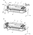
図1は、第1実施例の液体噴射システム1を説明するための図である。図1(A)は液体噴射システム1の第1の外観斜視図である。図1(B)は、液体噴射システム1の第2の外観斜視図であり、本発明の第1実施例の液体収容容器30を示した図である。なお、図1には方向を特定するために互いに直交するXYZ軸が図示されている。なお、これ以降の図に関しても必要に応じて互いに直交するXYZ軸が図示されている。
A. First embodiment:
A-1. Liquid injection system configuration:
FIG. 1 is a diagram for explaining a liquid ejection system 1 according to a first embodiment. FIG. 1A is a first external perspective view of the liquid ejecting system 1. FIG. 1B is a second external perspective view of the liquid ejecting system 1, and is a view showing the
図1(A)に示すように、液体噴射システム1は、液体噴射装置としてのインクジェットプリンター12(単に「プリンター12」ともいう。)と、プリンター12の外部に配置されたタンクユニット50とを備える。プリンター12は、用紙給紙部13と、用紙排出部14と、キャリッジ(サブタンク装着部)16と、4つのサブタンク20と、を備える。4つのサブタンク20は色の異なるインクをそれぞれ収容している。具体的には、4つのサブタンク20は、ブラックインクを収容するサブタンク20Bkと、シアンインクを収容するサブタンク20Cnと、マゼンダインクを収容するサブタンク20Maと、イエローインクを収容するサブタンク20Ywである。4つのサブタンク20は、キャリッジ16に搭載されている。
As shown in FIG. 1A, the liquid ejecting system 1 includes an ink jet printer 12 (also simply referred to as “
用紙給紙部13にセットされた印刷用紙は、プリンター12内部に搬送され、印刷後の印刷用紙が用紙排出部14から排出される。
The printing paper set in the
キャリッジ16は、主走査方向(紙巾方向、X軸方向)に移動可能である。この移動は、ステッピングモーター(図示せず)の駆動によりタイミングベルト(図示さず)を介して行われる。キャリッジ16の下面には、記録ヘッド(図示せず)が備え付けられている。この記録ヘッドの複数のノズルからインクが印刷用紙上に噴射され印刷が行われる。記録ヘッドは、圧電素子を用いてノズルからインクを噴射(吐出)する方式や、発熱体を用いて記録ヘッド内に気泡を生じさせてノズルからインクを噴射(吐出)する方式等を採用できる。なお、タイミングベルトやキャリッジ16等のプリンター12を構成する各種部品は、ケース10内部に収容されていることで保護されている。
The
図1(A)及び(B)に示すように、タンクユニット50はケース51と、ケース51に収容された液体収容容器としてのインクタンク30とを備える。図1(A)に示すように、ケース51は、上面ケース54と、第1の側面ケース56と、第2の側面ケース58と、底面ケース57を備える。ケース51は、ポリプロピレン(PP)やポリスチレン(PS)等の合成樹脂により成形することができる。本実施例では、ケース51はポリスチレンを用いて成形されると共に、所定の色(例えば、黒色)に着色され不透明である。ケース51によって、タンクユニット50がより安定して所定の場所(例えば、机や棚等のX軸とY軸とで規定される水平面)に設置される。
As shown in FIGS. 1A and 1B, the
4つのインクタンク30は、4つのサブタンク20が収容する色に対応したインクを収容している。すなわち、4つのインクタンク30は、ブラックインク、シアンインク、マゼンダインク、イエローインクをそれぞれ収容する。各インクタンク30は、所定の部分からインクの液面を外部から確認することができる。なお、インクタンク30は、サブタンク20よりも多くの量のインクを収容できる。
The four
各色のインクを収容したインクタンク30は、対応した色のインクを収容するためのサブタンク20にホース(チューブ)24によって接続されている。ホース24は合成ゴム等の可撓性を有する部材で形成されている。記録ヘッドからインクが噴射されサブタンク20のインクが消費されると、ホース24を介してインクタンク30のインクがサブタンク20に供給される。これにより、液体噴射システム1は、長時間に亘って中断動作なしに連続して印刷を続けることができる。なお、インクタンク30、ホース24及びサブタンク20とで本願発明の液体供給システムが構成されている。
The
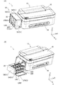
図2は、液体噴射システム1を説明するための第2の図である。図2(A)は、インクタンク30が使用状態である時の液体噴射システム1を示す図である。図2(B)は、インクタンク30が注入状態である時の液体噴射システム1を示す図である。ここで、「使用状態」とは、プリンター12にインクを供給する際の水平面に設置されたインクタンク30の状態である。言い換えると、使用状態では、後述する液体注入路304が水平方向に向かって開口している。ただし、開口は栓部材302によって塞がれている。また、使用状態では、後述する液体収容室340と空気収容室330が水平方向に並んでいる状態である。さらに、使用状態では後述する空気導入口352は、液体収容室340に収容された液体の液面より下方に位置する。また、「注入状態」とは、インクタンク30にインクが注入される際の水平面に設置されたインクタンク30の状態である。言い換えると、注入状態では、後述する液体注入路304が上方に向かって開口している。また、注入状態では、後述する液体収容室340と空気収容室330が鉛直方向に並んでいる状態である。さらに、注入状態では、後述する空気導入口352は、使用状態において液体収容室340に収容された液体の液面が直線LM1(「第1の状態表示線LM1」)にあるときの液量が液体収容室340に収容されている場合に、液体収容室340に収容された液体の液面より上方に位置している。
FIG. 2 is a second diagram for explaining the liquid ejecting system 1. FIG. 2A is a diagram illustrating the liquid ejecting system 1 when the
図2(A)に示すように、使用状態において、インクタンク30は、一部の壁(第1の壁)370C1が外部から視認可能な状態で設置される。使用状態において、第1の壁370C1は、X軸とY軸で規定される水平な設置面に対して立設状態となる壁である。また図2(B)に示すように、第1の壁370C1は、インクタンク30の注入状態において、インクタンク30の底面を構成する。なお本実施例では、使用状態において第1の壁370C1は、設置面に対して略垂直な壁である。なお、本実施例において「壁」は「壁部」とも呼ぶことができる。
As shown in FIG. 2A, in the use state, the
図2(A)に示すように、第1の壁370C1には、第1の状態識別部LB1(「補充開始識別部LB1」ともいう。)が設けられている。第1の状態識別部LB1は、使用状態において、インクタンク30が内部にインクを補充すべき第1の状態であることを利用者に識別させるために用いられる。詳細には、第1の状態識別部LB1は、インクタンク30の使用状態において、内部のインクが消費され、内部のインク液面が第1の高さになったことを識別するために設けられている。第1の状態識別部LB1は使用状態において水平となる直線LM1(「第1の状態表示線LM1」又は「補充開始表示線LM1」ともいう。)を含む。利用者は、インク液面が第1の状態表示線LM1の近傍に到達した場合に、インクをインクタンク30内部に補充する。
As shown in FIG. 2A, the first wall 370C1 is provided with a first state identifying unit LB1 (also referred to as “replenishment start identifying unit LB1”). The first state identification unit LB1 is used to allow the user to identify that the
図2(B)に示すように、インクタンク30内部にインクを注入(補充)する場合、使用状態から液体注入路304が鉛直上方(Z軸正方向)に向かって開口する注入状態に、利用者はインクタンク30の状態を変化させる。そして、上面ケース54を開ける。利用者は栓部材302を液体注入路304から取り外し、液体注入路304からインクを内部に注入する。ここで、液体注入路304が、「液体注入部」に相当する。
As shown in FIG. 2B, when ink is injected (replenished) into the
ここで、上面ケース54を開けることにより第1の壁370C1とは異なる第2の壁370C2が外部から視認可能となる。第2の壁370C2は、設置面に対して立設状態となる壁である。本実施例では、第2の壁370C2は、注入状態において設置面に対して略垂直な壁である。
Here, by opening the
第2の壁370C2には、第2の状態識別部LB2(「補充完了識別部LB2」ともいう。)が設けられている。第2の状態識別部LB2は、注入状態において、インクタンク30が内部へのインクの補充(注入)が完了した第2の状態であることを利用者に識別させるために用いられる。詳細には、第2の状態識別部LB2は、インクタンク30の注入状態において、内部にインクが補充され、内部のインク液面が第2の高さになったことを識別するために設けられている。第2の状態識別部LB2は注入状態において水平となる直線LM2(「第2の状態表示線LM2」又は「第2の状態表示線LM2」ともいう。)を含む。利用者は、インク液面が第2の状態表示線LM2の近傍に到達した場合に、インクの補充を停止する。
The second wall 370C2 is provided with a second state identifying unit LB2 (also referred to as “replenishment completion identifying unit LB2”). The second state identifying unit LB2 is used to allow the user to identify that the
A−2.インクタンク30の概略:
インクタンク30の詳細構成を説明する前に、理解の容易のために、大気開放口317から液体導出部306に至る経路について図3を参照して概念的に説明する。図3は、大気開放口317から液体導出部306に至る経路を概念的に示す図である。
A-2. Outline of ink tank 30:
Before describing the detailed configuration of the
大気開放口317から液体導出部306に至る経路(流路)は、大気開放流路300と、液体収容室340とに大きく分けられる。大気開放流路300は、上流から順に第1の流路310と、空気収容室330と、第2の流路としての液体室連通路350とから構成される。大気開放流路300は、一端である空気導入口352が液体収容室340で開口し、他端である大気開放口317が外部に向かって開口する。すなわち、大気開放口317は大気に連通している。使用状態において、液体室連通路350(詳細には、空気導入口352近傍)には、大気と直接に接する液面が形成され、空気導入口352から液体収容室340のインク中に空気(気泡)を導入することで液体収容室340に空気を導入する。
A path (flow path) from the atmosphere opening 317 to the
第1の流路310は、一端である大気導入口318(「空気室開口318」ともいう。)が空気収容室330で開口し、他端である大気開放口317が外部に向かって開口することで、空気収容室330と外部とを連通させる。第1の流路310は、連通流路320、気液分離室312、連通流路314と、を有する。連通流路320は、一端が大気開放口317に接続され、他端が気液分離室312に接続されている。連通流路320の一部は細長い流路であり、液体収容室340に貯留されたインクの水分が拡散により大気開放流路300から外部に蒸発することを抑制する。気液分離室312の上流から下流に向かう間には流路を塞ぐようにシート部材(フィルム部材)316が配置されている。このシート部材316は、気体を透過すると共に液体を透過しない性質を有する。シート部材316には、例えばゴアテックス(登録商標)などを用いることができる。このシート部材316を大気導入口318から大気開放口317に至る経路(流路)の途中を塞ぐように配置することで、液体収容室340から逆流してきたインクがシート部材316より上流側に流入することを抑制している。なお、このシート部材316はインクで一旦濡れると、気液分離膜としての本来の機能が損なわれ、空気を透過しなくなる場合がある。
The
連通流路314は、気液分離室312と空気収容室330とを連通させる。ここで、連通流路314の一端は大気導入口318である。
The
空気収容室330は、後述する液体室連通路350よりも流路断面積が大きく、所定の容積を有する。これにより、液体収容室340から逆流してきたインクを貯留し、空気収容室330よりも上流側にインクが流入することを抑制できる。
The
液体室連通路350は、一端である空気室側開口351が空気収容室330で開口し、他端である空気導入口352が液体収容室340で開口することで、空気収容室330と液体収容室340とを連通させる。また、液体室連通路350は、メニスカス(液面架橋)を形成可能な程度に流路断面積が小さいことが好ましい。
In the liquid
液体収容室340はインクを収容し、液体導出部306の液体出口349からホース24を介してサブタンク20(図1)にインクを流通させる。
The
さらに理解の容易のために、図4を用いてインクタンク30がサブタンク20にインクを供給する原理について説明する。図4は、インクタンク30からサブタンク20へのインク供給の原理について説明するための図である。図4には、インクタンク30をY軸正方向側から見た場合のインクタンク30が示されている。また、図4は、ホース24及びプリンター12の内部の様子を模式的に示している。
For easier understanding, the principle of the
本実施例のインクタンク30は、マリオットの瓶の原理を利用してインクをプリンター12に供給する。
The
液体噴射システム1は、所定の水平面sf上に設置されている。インクタンク30の液体導出部306と、サブタンク20の液体受入部202は、ホース24を介して接続されている。サブタンク20は、ポリスチレンやポリエチレン等の合成樹脂により成形されている。サブタンク20は、インク貯留室204と、インク流動路208と、フィルター206とを備える。インク流動路208には、キャリッジ16のインク供給針16aが挿入されている。フィルター206は、インクに異物等の不純物が混入していた場合に、その不純物を捕捉することで記録ヘッド17への不純物の流入を防止する。インク貯留室204のインクは、記録ヘッド17からの吸引によって、インク流動路208、インク供給針16aを流れて、記録ヘッド17に供給される。記録ヘッド17に供給されたインクは、ノズルを介して外部(印刷用紙)へ向かって噴射される。
The liquid ejection system 1 is installed on a predetermined horizontal plane sf. The
注入状態で液体注入路304からインクを液体収容室340に注入した後に、液体注入路304を栓部材302で密封し使用状態にした場合、液体収容室340内の空気が膨張し、液体収容室340は負圧になる。さらに、記録ヘッド17から液体収容室340のインクが吸引されることで液体収容室340は負圧に維持されている。
When ink is injected from the
使用状態において、空気導入口352は、第1の状態表示線LM1よりも下側に位置する。本実施例では、空気導入口352は、液体収容室340を区画形成する容器本体32のうち、使用状態において液体収容室340を挟んで下側に位置する底面壁370C3に形成されている。こうすることで、液体収容室340のインクが消費され、液体収容室340の液面が低下しても、大気と直接に接触する液面(大気接触液面)LAが長時間(インク液面が第1の状態表示線LM1に達する程度の時間)に亘り一定の高さに維持される。また、使用状態において、空気導入口352は、記録ヘッド17よりも低い位置になるように配置される。これにより、水頭差d1が発生する。なお、使用状態において、液体室連通路350の空気導入口352近傍にメニスカスである大気接触液面LAが形成された状態での水頭差d1を「定常時水頭差d1」とも呼ぶ。
In the use state, the
インク貯留室204のインクが記録ヘッド17によって吸引されることで、インク貯留室204は所定の負圧以上となる。インク貯留室204が所定の負圧以上になると、液体収容室340のインクがホース24を介してインク貯留室204に供給される。すなわち、インク貯留室204には、記録ヘッド17に流出した量のインクが液体収容室340から自動的に補充されることになる。言い換えれば、インクタンク30内の空気収容室330(すなわち、大気)と接するインク液面(大気接触液面)LAと、記録ヘッド(詳細にはノズル)との鉛直方向の高さの差によって発生する水頭差d1よりも、プリンター12側からの吸引力(負圧)がある程度大きくなることでインクが液体収容室340からインク貯留室204へ供給される。
As the ink in the
液体収容室340のインクが消費されると、空気収容室330の空気が液体室連通路350を介して液体収容室340に気泡Gとして導入される。これにより液体収容室340の液面は低下する。一方で、大気と直接に接する大気接触液面LAの高さは一定に維持されていることから、水頭差d1は一定に維持される。すなわち、記録ヘッド17の所定の吸引力により、インクタンク30から記録ヘッド17に安定してインクを供給することができる。
When the ink in the
ここで、本発明者らは、図4の左上の四角で囲んだ図のように、空気導入口352からインク中に気泡Gを発生させる際に、気泡Gが分裂し、通常想定される大きさの気泡Gaとは別に空気導入口352の大きさに対してかなり小さい微小気泡Gbが発生することを見出した。本実施例では、この微小気泡Gbは数十μm程度の直径を有する。微小気泡Gbの浮力は小さく(例えば、0.1mm/s)、液体収容室340のインクの流れの影響を特に受けやすい。本発明者らは、プリンター12を用いた高インクデューティによる連続印字などを行う場合、微小気泡Gbがインクの流れにのって液体導出部306を介してプリンター12側に流入し、ドット抜け等の不具合が生じやすくなることを見出した。
Here, as shown in the figure surrounded by the upper left square in FIG. 4, when the bubbles G are generated in the ink from the
A−3.インクタンクの詳細構成:
図5は、インクタンク30の第1の外観斜視図である。なお、図5では容器本体32にフィルム316,322が取り付けられる前の状態を示している。インクタンク30は、略柱体形状(詳細には略直角柱形状)である。インクタンク30は、容器本体32と、フィルム34,316,322とを備える。容器本体32は、ポリプロピレン等の合成樹脂により成形されている。また、容器本体32は半透明である。これにより利用者は外部から内部のインクの状態(インクの水位)を確認できる。
A-3. Detailed configuration of ink tank:
FIG. 5 is a first external perspective view of the
使用状態において、インクタンク30の側面を構成する側面壁には、第1の流路310が形成されている。気液分離室312の形状は凹状形状であり、凹状の底面には開口が形成されている。底面の開口を介して、気液分離室312と連通流路314とが連通する。連通流路314の末端は大気導入口318(図3)である。
In a use state, a
気液分離室312の底面を囲む内壁の全周には土手313が形成されている。フィルム316は、土手313に粘着されている。また、フィルム322は、第1の流路310のうち容器本体32の外面に形成された流路を覆うように容器本体32に粘着されている。これにより、連通流路320を形成すると共に、インクタンク30内部のインクが外部へ漏れ出すことを防止している。なお、連通流路320の一部分は、大気開放口317から気液分離室312までの距離を長くするために、気液分離室312の外周に沿って形成されている。これにより、容器本体32内部のインク中の水分が大気導入口318から外部へ蒸発することを抑制できる。
A
第1の流路310を流れる空気は、その途中で土手313に粘着された気液分離膜としてのフィルム316を通過することになる。これにより、容器本体32内部に収容されるインクが外部へ漏れ出すことをより抑制できる。
The air flowing through the
液体導出部306は筒状であり内部に流路を有する。この液体導出部306にホース24が接続される。また、液体導出部306の他端348は外部に向かって開口している。
The liquid lead-out
図6は、インクタンク30の第2の外観斜視図である。図7は、インクタンク30の第3の外観斜視図である。図6に示すように、容器本体32は一側面が開口した凹状形成であり、開口がフィルム34で塞がれることで内部に複数の小部屋が形成される。具体的には、主に、空気収容室330と液体収容室340と液体室連通路350が形成される。すなわち、容器本体32(外壁や内部のリブ等)とフィルム34とは、各部屋を区画形成する区画壁として機能する。なお、図6において、容器本体32のうち、フィルム34が熱溶着等により取り付けられる部分にはハッチングを施している。
FIG. 6 is a second external perspective view of the
液体室連通路350は、液体収容室330や空気収容室330よりも流路断面積が小さい流路である。詳細には、使用状態において、液体室連通路350はメニスカスを形成し維持可能な程度に流路断面積が小さい。
The liquid
液体収容室340は、使用状態において縦長の空間を形成している。液体収容室340には、液体を液体収容室340に注入するための液体注入路304が連通する。液体注入路304の一端である一端開口304mは液体収容室340で開口し、他端である他端開口304pは外部に向かって開口している。言い換えれば、液体収容室340は、液体を注入するための一端開口304mである液体注入口を有する。
The
ここで、上述のごとくインクタンク30は、使用状態と注入状態とで異なる状態となる。詳細には、使用状態と注入状態では、インクタンクの液体注入路304の外部に向かう開口方向304YPの向きが異なる。本実施例では、開口方向304YPは、使用状態では水平方向(X軸方向)であり、注入状態では鉛直方向(詳細にはZ軸上方向である鉛直上方向)である。ここで、開口方向304YPは、外部に向かって開口する他端開口304pの開口面に垂直な方向であって他端開口304pから外部に向かう方向である。なお、上記に限定されるものではなく、使用状態における開口方向304YPは、水平方向成分を有していれば良く、注入状態における開口方向304YPは鉛直上方向成分を有していれば良い。また、使用状態における開口方向304YPは、水平方向と成す角度が45°より小さいことが好ましく、水平方向であることがより好ましい。また注入状態における開口方向304YPは、鉛直上方向成分を有し鉛直方向と成す角度が45°よりも小さいことが好ましく、鉛直方向(詳細には、鉛直上方向)であることがより好ましい。なお、外部に向かって開口する他端開口304pとは、液体注入路304を塞ぐ栓部材302を液体注入路304から取り外した場合の状態を意味する。また、本実施例では、液体注入路304は、一端開口304mから他端開口304pに亘って真っ直ぐに延びる流路である。よって、インクタンク30の注入状態と使用状態とを別の観点から考えれば、以下のように規定できる。すなわち、本実施例では、「注入状態」とは液体注入路304が鉛直方向に延びる状態であり、「使用状態」とは液体注入路304が水平方向に延びる状態である。なお、上記に限定されるものではなく、「注入状態」とは液体注入路304が鉛直方向成分を有する方向に延びる状態であれば良く、「使用状態」とは液体注入路304が水平方向成分を有する方向に延びる状態でれば良い。また、「注入状態」は、液体注入路304が鉛直方向と成す角度が45°より小さい方向に延びる状態であることが好ましく、鉛直方向に延びる状態であることがより好ましい。また、「使用状態」は、液体注入路304が水平方向と成す角度が45°より小さい方向に延びる状態であることが好ましく、水平方向に延びる状態であることがより好ましい。また、使用状態と注入状態では、インクタンク30の底面を構成する壁部が異なる。
Here, as described above, the
液体収容室340は、第1の収容室340Fと第2の収容室340Sとを有する。インクタンク30の使用状態において、第1の収容室340Fは第2の収容室340Sよりも上側に位置する。第1の収容室340Fには一端開口304m及び空気導入口352が位置し、第2の収容室340Sには液体導出部306の一端である液体出口349が位置する。使用状態において、液体出口349は空気導入口352よりも下側に位置する。第1の収容室340Fと第2の収容室340Sは隣接して配置され、内部連通口345によって連通している。ここで、第1の収容室340Fは第2の収容室340Sよりも容積が大きく、液体収容室340のインクを主に収容するメイン室として機能する。
The
空気導入口352と内部連通口345とは、使用状態において第1の収容室340Fの底面を構成する底面壁370C3の異なる位置にそれぞれ形成されている。底面壁370C3は、使用状態において水平面を構成する。また、内部連通口345は、液体収容室区画壁のうち、使用状態において液体収容室340を挟んで第2の壁370C2と対向する底面壁370C3に位置する。また、液体出口349は、底面壁370C3とは異なる壁に形成されている。詳細には、液体出口349は、使用状態において水平面に対して立設状態(本実施例では、垂直状態)となる壁370C4に設けられている。
The
使用状態において液体出口349よりも上側に位置する空気導入口352は、液体収容室340に向かう開口方向352Dが鉛直上方向成分を有する。本実施例では、開口方向352Dは、鉛直上方向(Z軸正方向)である。これにより、空気導入口352から液体収容室340のインク中に導入された気泡(特に、微小気泡)が液体出口349まで到達する可能性を低減できる。特に、空気導入口352から液体出口349に微小気泡が到達するまでの時間を稼ぐことができる。よって、微小気泡のより多くを液体出口349に到達するまでに自己圧壊によって消滅させることができる。
The
液体出口349及び内部連通口345は、空気導入口352の開口面に垂直な方向に伸びる直線経路352Pであって、空気導入口352から液体収容室340に向かう直線経路352Pから外れた位置にある。直線経路352Pは、使用状態において鉛直方向に伸びる。
The
液体収容室340のうち、第1の収容室340Fの内部には、使用状態において鉛直方向成分を含む方向に伸びる内部壁382を有する。すなわち、内部壁382は、使用状態において水平面に対して立設状態にある。本実施例では、内部壁382は、使用状態において鉛直方向に伸びる。内部壁382は、使用状態において、空気導入口352及び液体出口349よりも上側に位置する。なお、ここで、内部壁382は、使用状態において、鉛直方向と45°以下の角度を成すように水平面に対して立設していることが好ましい。
Of the
液体収容室340は、内部壁382を挟む両側を連通させる第1の区画連通口382Vaと第2の区画連通口382Vbとを有する。本実施例では、第1の区画連通口382Vaは、内部壁382と、液体収容室区画壁32,34のうち使用状態において液体収容室340を挟んで上側に位置する上面壁370C2との間に間隙を設けることで形成されている。また、第2の区画連通口382Vbは、内部壁382と、液体収容室区画壁32,34のうち使用状態において液体収容室340を挟んで下側に位置する底面壁370C3との間に間隙を設けることで形成されている。すなわち、使用状態において、第1の区画連通口382Vaは第2の区画連通口382Vbよりも上側に位置する。なお、第1と第2の区画連通口382Va,382Vbは内部壁382自体に貫通孔や切り欠きを設けることで形成しても良い。
The
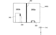
図8は、使用状態においてインクタンク30を水平面に垂直投影した場合の液体収容室340の投影図である。ここでは、垂直投影した場合における、液体収容室340の外枠340Gと、内部連通口345と、液体出口349と、空気導入口352と、内部壁382を示している。
FIG. 8 is a projection view of the
図8に示すように、垂直投影した場合の投影図(単に「投影図」ともいう。)において、空気導入口352と液体出口349とは重ならず、所定の間隔をあけて配置された位置関係にある。また、投影図において、空気導入口352と内部連通口345とは重ならない位置関係にある。ここで、投影図において、内部壁382は、液体収容室340を第1の区画室340Gaと第2の区画室340Gbとに区画する。投影図において、空気導入口352と内部連通口345は、内部壁382を挟んで両側にそれぞれ位置する。
As shown in FIG. 8, in a projection view (also simply referred to as “projection view”) in the case of vertical projection, the
図9は、使用状態において、液体収容室340のインクが消費される様子を示す図である。ここで、図9には、第2の状態におけるインク液面Lmax(「第2の液面Lmax」ともいう。)と、第1の状態におけるインク液面Lmin(「第1の液面Lmin」ともいう。)を破線で示している。
FIG. 9 is a diagram illustrating a state in which ink in the
プリンター12側の記録ヘッド17からインクが噴射されると、液体収容室340のインクが液体導出部306を介してプリンター12側に供給されると共に、空気導入口352から液体収容室340のインクに気泡Gが導入される。気泡Gは、インク中を上昇しインク液面LFに到達する。これにより、液体収容室340に空気が導入され、インク液面LFが低下する。
When ink is ejected from the recording head 17 on the
ここで、第1の収容室340Fから内部連通口345に向かう直線経路345Pであって、内部連通口345の開口面に垂直な方向に伸びる直線経路345Pを、液体収容室340から液体出口349に向かうインクの移動経路(「液体移動経路」ともいう。)345Pとする。また、直線経路352Pを気泡Gの移動経路(「気泡移動経路」ともいう。)352Pとする。本実施例では、液体移動経路345Pと気泡移動経路352Pとが重ならない位置関係にある。なお、液体収容室340が複数の室に区画されておらず単一の室から構成されている場合は、液体移動経路345Pは、内部連通口345を液体出口349に置き換えて規定することができる。
Here, a
上記のように、使用状態において、インクタンク30は、空気導入口352と液体出口349とが同一鉛直線上に位置しない位置関係にある。すなわち、投影図において空気導入口352と液体出口349とが重ならない位置関係にある(図8)。これにより、投影図において空気導入口352と液体出口349とが重なる位置関係にある場合に比べ、空気導入口352から導入された気泡G(特に、微小気泡Gb)が液体出口349に向かう可能性を低減できる。これにより、液体出口349を介して液体導出部306内に気泡Gが侵入する可能性を低減できる。
As described above, in the use state, the
インクタンク30は、液体移動経路345Pと気泡移動経路352Pとが重ならない位置関係にある。一般に、空気導入口352から液体収容室340に導入した気泡Gのより多くは、鉛直方向に伸びる気泡移動経路352Pやその近傍を通って上昇する。また、一般に、液体収容室340のインクは液体移動経路345Pやその近傍を通って液体出口349に向かう。本実施例では、気泡移動経路352Pと液体移動経路345Pとが重ならない位置にあることから、液体収容室340の気泡Gがインクの流れの影響を受けにくくできる。よって、空気導入口352から液体収容室340に導入した気泡Gが液体出口349に到達する可能性をより低減できる。
The
また、空気導入口352は使用状態において水平な壁である底面壁370C3に形成され、液体出口349は底面壁370C3とは異なる壁370C4に設けられている(図6)。すなわち、空気導入口352と液体出口349は、使用状態において水平方向成分を有する壁370C3を隔ててそれぞれ配置されている。すなわち、液体収容室340において、空気導入口352から液体出口349に至る最短の経路(「最短経路」又は「最短流路」ともいう。)が直線経路ではなく折れ曲がった経路となる。これにより、気泡Gが浮力やインクの流れにより移動した場合でも、使用状態において空気導入口352からインク中に導入した気泡Gが液体出口349に到達する可能性を低減できる。すなわち、折れ曲がった経路により、気泡Gが空気導入口352から液体出口349までに至るまでの時間(到達時間)を稼ぐことができる。すなわち、折れ曲がった経路によって到達時間をより長くすることで、より多くの微小気泡Gbを液体収容室340に位置する間に自己圧壊作用によってインク中に溶解させることができる。よって、微小気泡Gbを含む気泡Gが液体出口349を介してプリンター12側に流入してドット抜け等の不具合の発生が生じる可能性を低減できる。
In addition, the
また、使用状態において、液体出口349は空気導入口352よりも下側に位置すると共に、空気導入口352の開口方向352Dは鉛直方向上向きである(図6)。これにより、空気導入口352から液体収容室340の液中に導入した気泡Gのより多くは、鉛直上向きに上昇することから、気泡Gが液体出口に到達する可能性をより低減できる。
In the use state, the
また上記実施例では、空気導入口352が位置する第1の収容室340Fと液体出口349が位置する第2の収容室340Sとを連通する内部連通口345が、直線経路352Pから外れた位置にある(図9)。これにより、気泡Gが内部連通口345に到達する可能性を低減できる。よって、気泡Gが第2の収容室340Sに位置する液体出口349に到達する可能性をより低減できる。
Further, in the above embodiment, the
さらに、液体収容室340は、使用状態において鉛直方向に伸びる内部壁382であって、使用状態において空気導入口352及び液体出口349よりも上側に位置する内部壁382を有する(図9)。この内部壁382は、投影図において空気導入口352と液体出口349とに挟まれた位置にある(図8)。よって、内部壁382が障壁となって、気泡Gが内部壁382に対して空気導入口352が位置する側(第1の区画室340Ga)から液体出口349が位置する側(第2の区画室340Gb)に移動することを抑制できる。よって、気泡Gが液体出口349に到達する可能性をより一層低減できる。
Furthermore, the
また、液体収容室340は、第1の区画連通口382Vaと、使用状態において第1の区画連通口382Vaよりも下側に位置する第2の区画連通口382Vbとを有する(図9)。これにより、第1の区画室340Gaと第2の区画室340Gbにおける空気の循環とインクの循環とがそれぞれ妨げられる可能性を低減できる。すなわち、第1の区画室340Gaと第2の区画室340Gbのそれぞれの液面高さを同じ高さにすることができると共に、液体収容室340全体のインク濃度の分布のばらつきを低減できる。
In addition, the
特に、本実施例では、第1の区画連通口382Vaが上面壁370C2と接して形成され、第2の区画連通口382Vbが底面壁370C3と接して形成されている。これにより、第2の状態から第1の状態に至る期間(「全使用期間」ともいう。)において、第1の区画室340Gaと第2の区画室340Gbを介した空気の循環とインクの循環とがそれぞれ妨げられる可能性を低減できる。 In particular, in this embodiment, the first partition communication port 382Va is formed in contact with the upper surface wall 370C2, and the second partition communication port 382Vb is formed in contact with the bottom wall 370C3. Thus, in the period from the second state to the first state (also referred to as “all use period”), air circulation and ink circulation through the first compartment 340Ga and the second compartment 340Gb. The possibility of being disturbed can be reduced.
また、上記実施例では、液体注入路304の一端開口304mが液体収容室340で開口している(図6)。すなわち、注入状態において、液体注入路304からインクを注入すると、インクは空気収容室330を経由することなく直接に液体収容室340に注入される。よって、インクタンク30内にインクが過多に注入され、空気収容室330に導入される可能性を低減できる。これにより、大気接触液面LAをより一定高さに維持できることから、定常時水頭差d1(図4)をより安定に維持できる。
In the above embodiment, the one
B.第2実施例:
図10は、第2実施例のインクタンク30aについて説明するための図である。第1実施例のインクタンク30(図9)との違いは、内部壁382aと第2の区画連通口382Vb1の構成である。その他の構成については、第1実施例と同様の構成であるため、同様の構成については第1実施例と同一の符号を付すと共に説明を省略する。また、液体噴射システム1のその他の構成(例えば、プリンター12)は第1実施例と同様であるため説明を省略する。
B. Second embodiment:
FIG. 10 is a diagram for explaining the
第2実施例のインクタンク30aは、内部壁382aが単一の壁である。また、使用状態において、内部壁382aは少なくとも第2の状態におけるインク液面Lmaxから第1の状態におけるインク液面Lminに亘って位置する。本実施例では、内部壁382aの上端382a2はインク液面Lmaxよりも上側に位置し、下端382a3はインク液面Lminよりも下側に位置する。すなわち、第2の区画連通口382Vb1は、第1の状態におけるインク液面Lminよりも下側に位置する。また、内部壁382aは、貫通孔が形成されることなく板状であり、第1と第2の区画連通口382Va,382Vb1を介してのみ第1と第2の区画室340Ga,340Gbとが連通する。
In the
上記のように、第2実施例のインクタンク30aは、全使用期間において、第1の区画連通口382Vaが空気と接し、第2の区画連通口382Vb1がインクと接する。よって、全使用期間において内部壁382aを挟む両側340Ga,340Gbの空気とインクのそれぞれの循環が妨げられる可能性を低減できる。また、内部壁382aが全使用期間においてインク液面高さの位置に存在することから、第1の区画室340Gaの液面近傍の気泡Gが第2の区画室340Gbに移動することを抑制できる。これにより、気泡Gが液体出口349に到達する可能性をより一層低減できる。また、第2実施例のインクタンク30aは、投影図において空気導入口352と液体出口349とが重ならない位置関係にあることから、第1実施例と同様に、空気導入口352と液体出口349とが重なる位置関係にある場合に比べ、気泡G(特に、微小気泡Gb)が液体出口349に向かう可能性を低減できる。
As described above, in the
C.第3実施例:
図11は、第3実施例のインクタンク30bについて説明するための図である。第1実施例のインクタンク30(図9)との違いは、対向壁340Pを有する点と、空気導入口352の開口方向352Dである。その他の構成については、第1実施例と同様の構成であるため、同様の構成については第1実施例と同一の符号を付すと共に説明を省略する。また、液体噴射システム1のその他の構成(例えば、プリンター12)は第1実施例と同様であるため説明を省略する。
C. Third embodiment:
FIG. 11 is a diagram for explaining the
第3実施例のインクタンク30bは、液体収容室340が空気導入口352と向かい合う対向壁340Pを有する。また、液体出口349は、空気導入口352と対向壁340Pとの間の液体収容室の部分には位置することなく、他の部分(壁370C4)に位置する。また、使用状態において、空気導入口352の開口方向352Dは水平方向であって、液体出口349に向かう方向(X軸負方向)である。
The
上記のように第3実施例のインクタンク30bは、投影図において空気導入口352と液体出口349とが重ならない位置関係にあることから、第1実施例と同様に、空気導入口352と液体出口349とが重なる位置関係にある場合に比べ、気泡G(特に、微小気泡Gb)が液体出口349に向かう可能性を低減できる。また、第3実施例のインクタンク30bは、対向壁340Pによって、空気導入口352から導入された気泡の液体出口349への進行を抑制できる。これにより、気泡Gが液体出口349に到達する可能性をより低減でき、気泡Gが液体導出部306内に侵入する可能性をより低減できる。
As described above, the
D.変形例:
なお、本発明の上記実施例や実施形態に限られるものではなく、その要旨を逸脱しない範囲において種々の形態において実施することが可能であり、例えば次のような変形も可能である。
D. Variation:
In addition, it is not restricted to the said Example and embodiment of this invention, In the range which does not deviate from the summary, it can implement in a various form, For example, the following deformation | transformation is also possible.
D−1.第1変形例:
上記実施例では、投影図において、空気導入口352と液体出口349とが重ならない関係にあったが、これに限定されるものではない。例えば、空気導入口352と液体出口349を結ぶ最短経路が折れ曲がった経路であっても良い。すなわち、以下の態様としてもインクタンクは実施できる。
D-1. First modification:
In the above embodiment, the
態様1:対象物に液体を噴射するためのヘッドに前記液体を供給するための液体収容容器であって、
前記液体を収容するための液体収容室と、
一端である一端開口が前記液体収容室で開口し、前記液体収容室に前記液体を注入するための液体注入路と、
一端である空気導入口が前記液体収容室で開口し、他端である大気開放口が外部に向かって開口する大気開放流路であって、前記液体収容室の液中に空気を導入することで前記液体収容室に空気を導入するための大気開放流路と、
一端である液体出口が前記液体収容室で開口し、他端が外部に向かって開口する液体導出部であって、前記液体収容室に収容される前記液体を外部に流通させる液体導出部と、を備え、
前記液体収容室において、前記空気導入口から前記液体出口までの最短経路は少なくとも一部に折れ曲がった経路を有する、液体収容容器。
こうすることで、空気導入口から液体収容室の液中に導入された気泡が液体出口349まで到達する可能性を低減できる。
Aspect 1: A liquid container for supplying the liquid to a head for ejecting the liquid onto the object,
A liquid storage chamber for storing the liquid;
One end opening which is one end is opened in the liquid storage chamber, and a liquid injection path for injecting the liquid into the liquid storage chamber;
An air opening passage having an air inlet opening at one end opened in the liquid storage chamber and an air opening opening at the other end opened to the outside, wherein air is introduced into the liquid in the liquid storage chamber. And an open air channel for introducing air into the liquid storage chamber,
A liquid outlet that opens at the liquid storage chamber at one end and opens toward the outside at the other end, and a liquid outlet for circulating the liquid stored in the liquid storage chamber; With
In the liquid storage chamber, the shortest path from the air inlet to the liquid outlet has a path bent at least partially.
By doing so, the possibility that bubbles introduced from the air inlet into the liquid in the liquid storage chamber reach the
例えば、第1実施例のインクタンク30では(図6)、折れ曲がった経路は、空気導入口352を出てすぐにX軸負方向側に90°折れ曲がり、内部連通口345を通る際にZ軸負方向側に90°折れ曲がり、X軸方向に蛇行しながらZ軸負方向に進む経路となる。
For example, in the
態様2:態様1に記載の液体収容容器であって、
前記折れ曲がった経路は、屈曲した屈曲部を少なくとも2箇所以上有する、液体収容容器。
こうすることで、空気導入口352から液体収容室340の液中に導入された気泡Gが液体出口349に到達する可能性をより低減できる。また、屈曲部は、90°以下の角度で屈曲していることが好ましい。これにより、気泡Gの空気導入口から液体出口への進行をより抑制できる。
Aspect 2: The liquid container according to Aspect 1,
The bent path is a liquid container having at least two bent portions that are bent.
By doing so, the possibility that the bubbles G introduced into the liquid in the
態様3:態様1又は態様2に記載の液体収容容器であって、
前記ヘッドに前記液体を供給する際の使用状態において、前記空気導入口は前記液体出口よりも上側に位置する、液体収容容器。
気泡は浮力により上昇し得る。態様3の構成により、使用状態において空気導入口352から液体出口349に気泡が到達する可能性をより低減できる。
Aspect 3: The liquid container according to Aspect 1 or Aspect 2,
The liquid storage container, wherein the air inlet is positioned above the liquid outlet in a use state when supplying the liquid to the head.
Bubbles can rise by buoyancy. With the configuration of the aspect 3, it is possible to further reduce the possibility of bubbles reaching the
態様4:態様1乃至態様3のいずれか1つに記載の液体収容容器であって、
前記液体収容室は、前記ヘッドに前記液体を供給する際の使用状態において、
前記空気導入口が位置する第1の収容室と、
前記液体出口が位置し、前記第1の収容室よりも下側の位置で前記第1の収容室に隣接して配置された第2の収容室と、
前記第1と第2の収容室とを連通させる内部連通口と、を備え、
前記使用状態において、
前記空気導入口の前記液体収容室に向かう導入開口方向であって開口面に垂直な導入開口方向は、鉛直上方向成分を有し、
前記内部連通口の内部開口方向であって開口面に垂直な内部開口方向は、鉛直方向成分を有し、
前記折れ曲がった経路は、前記空気導入口から前記内部連通口に至る経路によって形成される。
態様4によれば、容易に折れ曲がった経路を形成できる。
また、導入開口方向及び内部開口方向は、鉛直方向と45°以下の角度を成すことが好ましく、鉛直方向であることがより好ましい。上記第1実施例では、導入開口方向352Dは鉛直上方向であり、内部開口方向は鉛直方向である。
Aspect 4: The liquid container according to any one of Aspects 1 to 3,
In the use state when the liquid storage chamber supplies the liquid to the head,
A first storage chamber in which the air inlet is located;
A second storage chamber located adjacent to the first storage chamber at a position below the first storage chamber, the liquid outlet being located;
An internal communication port for communicating the first and second storage chambers,
In the use state,
The introduction opening direction that is the introduction opening direction toward the liquid storage chamber of the air introduction port and is perpendicular to the opening surface has a vertical upward component,
The internal opening direction of the internal communication opening that is perpendicular to the opening surface has a vertical component,
The bent path is formed by a path from the air introduction port to the internal communication port.
According to the aspect 4, the path | route bent easily can be formed.
The introduction opening direction and the internal opening direction preferably form an angle of 45 ° or less with the vertical direction, and more preferably the vertical direction. In the first embodiment, the
上記態様1〜4に加え、発明を解決するための手段の各適用例に記載の要件を態様1〜4に加えても良い。 In addition to the above aspects 1 to 4, the requirements described in each application example of means for solving the invention may be added to aspects 1 to 4.
D−2.第2変形例:
上記実施例では、第1の状態識別部LB1や第2の状態識別部LB2はインクタンク30に設けられていたが(図2)、これに限定されるものではなく、第1の状態や第2の状態を識別できる態様であれば良い。例えば、インクタンク30とは別体の定規を第1の状態識別部LB1や第2の状態識別部LB2として用いても良い。また、例えばセンサーを第1と第2の状態識別部LB1,LB2として用いて第1の状態や第2の状態を識別しても良い。
D-2. Second modification:
In the above embodiment, the first state identifying unit LB1 and the second state identifying unit LB2 are provided in the ink tank 30 (FIG. 2). However, the present invention is not limited to this, and the first state and the second state identifying unit LB2 are not limited thereto. Any mode that can identify the state of 2 is acceptable. For example, a ruler separate from the
D−3.第3変形例:
上記実施例では、インクタンク30の使用状態において、空気導入口352は液体出口349よりも上側に位置していたがこれに限定されるものではなく、気泡導入経路352Pと液体移動経路345Pとが重なれなければ、空気導入口352と液体出口349とは任意の位置関係で良い。
D-3. Third modification:
In the above embodiment, the
D−4.第4変形例:
上記実施例では、液体収容容器としてプリンター12に用いられるインクタンク30,30a,30bを例に説明を行ったが、これに限定されるものではなく、例えば液晶ディスプレー等の色材噴射ヘッドを備えた装置、有機ELディスプレー、面発光ディスプレー(FED)等の電極形成に用いられる電極材(導電ペースト)噴射ヘッドを備えた装置、バイオチップ製造に用いられる生体有機物噴射ヘッドを備えた装置、精密ピペットとしての試料噴射ヘッドを備えた装置、捺染装置やマイクロディスペンサ等の液体噴射装置に対し、マリオットの瓶の原理を利用して液体を供給可能な液体収容容器であって、液体注入路を備える液体収容容器に本発明は適用できる。上記の各種の液体噴射装置に液体収容容器を使用する際には、各種の液体噴射装置が噴射する液体の種類に応じた液体(色材,導電ペースト,生体有機物等)を、液体収容容器内部に収容すれば良い。また、各種液体噴射装置と各種液体噴射装置に用いる液体収容容器を備える液体噴射システムとしても本発明は適用可能である。
D-4. Fourth modification:
In the above embodiment, the
1…液体噴射システム
10…ケース
12…インクジェットプリンター(プリンター)
13…用紙給紙部
14…用紙排出部
16…キャリッジ
16a…インク供給針
17…記録ヘッド
20…サブタンク
24…ホース
30,30a,30b…液体収容容器(インクタンク)
32…容器本体(液体収容室区画壁)
34…フィルム(液体収容室区画壁)
50…タンクユニット
54…上面ケース
56…第1の側面ケース
57…底面ケース
58…第2の側面ケース
202…液体受入部
204…インク貯留室
206…フィルター
208…インク流動路
300…大気開放流路
302…栓部材
304…液体注入路
304m…一端開口
304p…他端開口
306…液体導出部
310…第1の流路
312…気液分離室
313…土手
314…連通流路
316…フィルム(シート部材)
317…大気開放口
318…大気導入口
320…連通流路
322…フィルム
330…空気収容室
340…液体収容室
340F…第1の収容室
340P…対向壁
340S…第2の収容室
340Ga…第1の区画室
340Gb…第2の区画室
345…内部連通口
345P…液体移動経路(直線経路)
349…液体出口
350…液体室連通路
351…空気室側開口
352…空気導入口
352D…開口方向
352P…気泡移動経路(直線経路)
370C1…第1の壁
370C2…第2の壁(上面壁)
370C3…底面壁
370C4…壁
382…内部壁
382a…内部壁
382a2…上端
382a3…下端
382Va…第1の区画連通口
382Vb,382Vb1…第2の区画連通口
G…気泡
Lmax…インク液面
Lmin…インク液面
d1…定常時水頭差
LA…大気接触液面
LF…インク液面
Ga…気泡
Gb…微小気泡
sf…水平面
LB1…第1の状態識別部
LB2…第2の状態識別部
LM1…第1の状態表示線
LM2…第2の状態表示線
DESCRIPTION OF SYMBOLS 1 ...
DESCRIPTION OF
32 ... Container body (Liquid chamber compartment wall)
34 ... Film (Liquid chamber compartment wall)
DESCRIPTION OF
317 ...
349 ...
370C1 ... 1st wall 370C2 ... 2nd wall (upper surface wall)
370C3 ... bottom wall 370C4 ...
Claims (12)
前記液体を収容するための液体収容室と、
一端である一端開口が前記液体収容室で開口し、前記液体収容室に前記液体を注入するための液体注入部と、
一端である空気導入口が前記液体収容室で開口し、他端である大気開放口が大気に連通する大気開放流路であって、前記液体収容室の液中に気泡を発生させて前記液体収容室に空気を導入するための大気開放流路と、
一端である液体出口が前記液体収容室で開口し、他端が外部に向かって開口する液体導出部であって、前記液体収容室に収容される前記液体を導出させる液体導出部と、を備え、
前記ヘッドに前記液体を供給する際の使用状態において、水平面に前記液体収容容器を垂直投影した場合に、前記空気導入口と前記液体出口とが重ならない位置関係にあり、
前記大気開放流路は、前記液体注入部とは異なる位置に形成され、
前記大気開放口は、前記液体注入部が形成された壁とは異なる壁に形成されている、液体収容容器。 A liquid container for supplying the liquid to a head for ejecting the liquid onto the object,
A liquid storage chamber for storing the liquid;
One end opening which is one end opens in the liquid storage chamber, and a liquid injection part for injecting the liquid into the liquid storage chamber;
An air introduction port that is one end opens in the liquid storage chamber, and an air release port that is the other end communicates with the atmosphere, and the liquid is generated by generating bubbles in the liquid in the liquid storage chamber. An open air channel for introducing air into the containment chamber;
A liquid outlet that opens at the liquid storage chamber at one end and opens toward the outside at the other end, and a liquid outlet for leading out the liquid stored in the liquid storage chamber. ,
In use state when supplying the liquid to the head, when the liquid container was vertically projected on a horizontal plane, Ri positional relationship near said air inlet and said liquid outlet does not overlap,
The atmosphere opening flow path is formed at a position different from the liquid injection part,
The atmosphere opening is a liquid container formed on a wall different from the wall on which the liquid injection part is formed .
前記液体収容室は、液体収容室区画壁により区画形成され、
前記空気導入口と前記液体出口とは、それぞれ前記液体収容室区画壁に形成され、かつ、前記液体収容室区画壁のうち前記使用状態において水平方向成分を有する部分を少なくとも隔てて位置する、液体収容容器。 The liquid container according to claim 1,
The liquid storage chamber is partitioned by a liquid storage chamber partition wall,
The air introduction port and the liquid outlet are respectively formed on the liquid storage chamber partition wall, and are located at least apart from the liquid storage chamber partition wall having a horizontal component in the use state. Containment container.
前記液体収容室は、前記空気導入口に向かい合う対向壁を有し、
前記液体出口は、前記空気導入口と前記対向壁との間の前記液体収容室の部分には位置することなく、他の部分に位置する、液体収容容器。 The liquid container according to claim 1,
The liquid storage chamber has an opposing wall facing the air inlet,
The liquid outlet is a liquid storage container that is not positioned in the portion of the liquid storage chamber between the air inlet and the opposing wall, but is positioned in another portion.
前記液体出口は、前記空気導入口の開口面と垂直な方向に伸びる直線経路であって、前記空気導入口から前記液体収容室に向かう直線経路から外れた位置にある、液体収容容器。 The liquid container according to any one of claims 1 to 3,
The liquid outlet is a liquid storage container, which is a straight path extending in a direction perpendicular to the opening surface of the air introduction port and is out of a straight path from the air introduction port to the liquid storage chamber.
前記使用状態において、前記液体出口は前記空気導入口よりも下側に位置し、
前記使用状態において、前記空気導入口の開口面に垂直な開口方向であって前記液体収容室に向かう開口方向は鉛直上方向成分を有する、液体収容容器。 The liquid container according to any one of claims 1 to 4,
In the use state, the liquid outlet is located below the air inlet,
In the use state, a liquid storage container in which an opening direction perpendicular to an opening surface of the air introduction port and toward the liquid storage chamber has a vertically upward component.
前記液体を収容するための液体収容室と、
一端である一端開口が前記液体収容室で開口し、前記液体収容室に前記液体を注入するための液体注入部と、
一端である空気導入口が前記液体収容室で開口し、他端である大気開放口が大気に連通する大気開放流路であって、前記液体収容室の液中に気泡を発生させて前記液体収容室に空気を導入するための大気開放流路と、
一端である液体出口が前記液体収容室で開口し、他端が外部に向かって開口する液体導出部であって、前記液体収容室に収容される前記液体を導出させる液体導出部と、を備え、
前記ヘッドに前記液体を供給する際の使用状態において、水平面に前記液体収容容器を垂直投影した場合に、前記空気導入口と前記液体出口とが重ならない位置関係にあり、
前記液体収容室は、
前記空気導入口が位置する第1の収容室と、
前記第1の収容室に隣接して配置され、前記液体導出部の前記液体出口が位置する第2の収容室と、
前記第1の収容室と前記第2の収容室とを連通させる内部連通口と、を有し、
前記内部連通口は、前記空気導入口の開口面と垂直な方向に伸びる直線経路であって、前記空気導入口から前記液体収容室に向かう直線経路から外れた位置にある、液体収容容器。 A liquid container for supplying the liquid to a head for ejecting the liquid onto the object ,
A liquid storage chamber for storing the liquid;
One end opening which is one end opens in the liquid storage chamber, and a liquid injection part for injecting the liquid into the liquid storage chamber;
An air introduction port that is one end opens in the liquid storage chamber, and an air release port that is the other end communicates with the atmosphere, and the liquid is generated by generating bubbles in the liquid in the liquid storage chamber. An open air channel for introducing air into the containment chamber;
A liquid outlet that opens at the liquid storage chamber at one end and opens toward the outside at the other end, and a liquid outlet for leading out the liquid stored in the liquid storage chamber. ,
In the state of use when supplying the liquid to the head, when the liquid container is vertically projected on a horizontal plane, the air inlet and the liquid outlet are in a positional relationship such that they do not overlap,
The liquid storage chamber is
A first storage chamber in which the air inlet is located;
A second storage chamber disposed adjacent to the first storage chamber and in which the liquid outlet of the liquid outlet is located;
An internal communication port for communicating the first storage chamber and the second storage chamber;
The internal communication port is a liquid storage container that is a straight path extending in a direction perpendicular to the opening surface of the air introduction port and is out of a straight path from the air introduction port to the liquid storage chamber.
前記液体収容室は、
内部に配置され、前記使用状態において鉛直方向成分を含む方向に伸びる内部壁であって、少なくとも一部が前記使用状態において前記空気導入口及び前記液体出口よりも上側に位置する内部壁を有し、
前記使用状態において、前記水平面に前記液体収容容器を垂直投影した場合に、前記内部壁を挟んだ位置に前記空気導入口と前記液体出口とがそれぞれ位置する、液体収容容器。 The liquid container according to claim 6 ,
The liquid storage chamber is
An internal wall disposed inside and extending in a direction including a vertical component in the use state, wherein at least a part of the internal wall is located above the air inlet and the liquid outlet in the use state ,
In the use state, when the liquid container is vertically projected on the horizontal plane, the air inlet and the liquid outlet are respectively positioned at positions sandwiching the inner wall.
前記液体収容室は、
前記内部壁を挟む両側を連通させる第1と第2の区画連通口を有し、
前記使用状態において、前記第1と第2の区画連通口は異なる高さに位置する、液体収容容器。 The liquid container according to claim 7,
The liquid storage chamber is
Having first and second compartment communication ports for communicating both sides of the inner wall;
In the use state, the first and second partition communication ports are located at different heights.
前記第1の区画連通口は、前記使用状態において前記液体収容室を挟んで上側に位置する上面壁と接して形成され、
前記第2の区画連通口は、前記使用状態において前記液体収容室を挟んで下側に位置する底面壁と接して形成されている、液体収容容器。 The liquid container according to claim 8, wherein
The first partition communication port is formed in contact with an upper surface wall located above the liquid storage chamber in the use state,
The second compartment communication port is a liquid storage container formed in contact with a bottom wall located on the lower side of the liquid storage chamber in the use state.
前記使用状態において、
前記第1の区画連通口は、少なくとも一部が、前記液体収容室への前記液体の補充が完了した第2の状態における前記液体収容室の液面より上側に位置し、
前記第2の区画連通口は、前記液体収容室の前記液体が消費され前記液体収容室に前記液体を補充すべき第1の状態における前記液体収容室の液面よりも下側に位置する、液体収容容器。 The liquid container according to claim 8 or 9, wherein
In the use state,
The first compartment communication port is located at least partially above the liquid surface of the liquid storage chamber in the second state in which the liquid supply to the liquid storage chamber is completed.
The second compartment communication port is located below the liquid surface of the liquid storage chamber in the first state in which the liquid in the liquid storage chamber is consumed and the liquid storage chamber should be replenished with the liquid. Liquid container.
請求項1乃至請求項10のいずれか一項に記載の液体収容容器と、
対象物に前記液体を噴射するためのヘッドを有する液体噴射装置と、
前記液体収容容器と前記液体噴射装置とを接続し、前記液体収容室の前記液体を前記液
体噴射装置に流通させる流通管と、を備える、液体噴射システム。 A liquid ejection system,
The liquid container according to any one of claims 1 to 10,
A liquid ejecting apparatus having a head for ejecting the liquid onto an object;
A liquid ejecting system comprising: a flow pipe that connects the liquid container and the liquid ejecting apparatus and causes the liquid in the liquid storage chamber to circulate through the liquid ejecting apparatus.
請求項1乃至請求項10のいずれか一項に記載の液体収容容器と、
対象物に前記液体を噴射するためのヘッドに流通する前記液体が流れる液体流動路を有するサブタンクと、
前記液体収容容器と前記サブタンクとを接続し、前記液体収容容器の前記液体を前記サブタンクに流通させる流通管と、を備える、液体供給システム。 A liquid supply system,
The liquid container according to any one of claims 1 to 10,
A sub-tank having a liquid flow path through which the liquid flowing in a head for injecting the liquid onto an object flows;
A liquid supply system comprising: a flow pipe that connects the liquid storage container and the sub tank and distributes the liquid in the liquid storage container to the sub tank.
Priority Applications (2)
| Application Number | Priority Date | Filing Date | Title |
|---|---|---|---|
| JP2011165018A JP5838633B2 (en) | 2011-07-28 | 2011-07-28 | Liquid container, liquid ejection system, and liquid supply system |
| CN 201220376402 CN203198406U (en) | 2011-07-28 | 2012-07-30 | Liquid accommodating container, liquid injection system and liquid supply system |
Applications Claiming Priority (1)
| Application Number | Priority Date | Filing Date | Title |
|---|---|---|---|
| JP2011165018A JP5838633B2 (en) | 2011-07-28 | 2011-07-28 | Liquid container, liquid ejection system, and liquid supply system |
Publications (3)
| Publication Number | Publication Date |
|---|---|
| JP2011240705A JP2011240705A (en) | 2011-12-01 |
| JP2011240705A5 JP2011240705A5 (en) | 2014-09-11 |
| JP5838633B2 true JP5838633B2 (en) | 2016-01-06 |
Family
ID=45407827
Family Applications (1)
| Application Number | Title | Priority Date | Filing Date |
|---|---|---|---|
| JP2011165018A Active JP5838633B2 (en) | 2011-07-28 | 2011-07-28 | Liquid container, liquid ejection system, and liquid supply system |
Country Status (2)
| Country | Link |
|---|---|
| JP (1) | JP5838633B2 (en) |
| CN (1) | CN203198406U (en) |
Families Citing this family (17)
| Publication number | Priority date | Publication date | Assignee | Title |
|---|---|---|---|---|
| JP6044068B2 (en) * | 2011-12-14 | 2016-12-14 | セイコーエプソン株式会社 | Recording device |
| JP5927918B2 (en) * | 2012-01-12 | 2016-06-01 | セイコーエプソン株式会社 | Liquid container and liquid consuming device |
| JP6037111B2 (en) * | 2012-11-02 | 2016-11-30 | セイコーエプソン株式会社 | Ink for inkjet recording, inkjet recording system |
| JP6065622B2 (en) * | 2013-02-05 | 2017-01-25 | セイコーエプソン株式会社 | Inkjet ink set and inkjet recording system |
| JP2015061748A (en) * | 2013-08-19 | 2015-04-02 | セイコーエプソン株式会社 | Ink container |
| JP2015061749A (en) * | 2013-08-19 | 2015-04-02 | セイコーエプソン株式会社 | Ink container |
| JP6287510B2 (en) * | 2014-04-08 | 2018-03-07 | ブラザー工業株式会社 | Liquid consumption device |
| JP2015199261A (en) | 2014-04-08 | 2015-11-12 | ブラザー工業株式会社 | Liquid discharge device |
| JP6387693B2 (en) * | 2014-06-12 | 2018-09-12 | ブラザー工業株式会社 | tank |
| JP2017081124A (en) * | 2015-10-30 | 2017-05-18 | キヤノン株式会社 | Ink tank and inkjet recording device |
| US10040295B2 (en) * | 2016-02-29 | 2018-08-07 | Seiko Epson Corporation | Liquid supply device, and liquid ejection system |
| JP6929616B2 (en) * | 2016-04-08 | 2021-09-01 | キヤノン株式会社 | Liquid discharge device |
| WO2018160159A1 (en) | 2017-02-28 | 2018-09-07 | Hewlett-Packard Development Company, L.P. | Reservoir and bubble structure |
| JP7056329B2 (en) * | 2018-04-03 | 2022-04-19 | セイコーエプソン株式会社 | Liquid sprayer |
| JP7218528B2 (en) * | 2018-09-28 | 2023-02-07 | ブラザー工業株式会社 | liquid consumption device |
| JP6766222B2 (en) * | 2019-06-11 | 2020-10-07 | キヤノン株式会社 | Inkjet recording device |
| JP7183222B2 (en) * | 2020-08-20 | 2022-12-05 | キヤノン株式会社 | Liquid storage container and recording device |
Family Cites Families (5)
| Publication number | Priority date | Publication date | Assignee | Title |
|---|---|---|---|---|
| JPH058489Y2 (en) * | 1987-06-23 | 1993-03-03 | ||
| JPH11138839A (en) * | 1997-11-14 | 1999-05-25 | Brother Ind Ltd | Ink supplying device |
| JP4209236B2 (en) * | 2003-03-28 | 2009-01-14 | シャープ株式会社 | Ink supply device |
| ITMI20031153A1 (en) * | 2003-06-06 | 2004-12-07 | Anteprima S R L | INK SUPPLY SYSTEM FOR PRINTERS A |
| JP2007237552A (en) * | 2006-03-08 | 2007-09-20 | Fuji Xerox Co Ltd | Liquid droplet discharge unit, and droplet discharge apparatus |
-
2011
- 2011-07-28 JP JP2011165018A patent/JP5838633B2/en active Active
-
2012
- 2012-07-30 CN CN 201220376402 patent/CN203198406U/en not_active Expired - Fee Related
Also Published As
| Publication number | Publication date |
|---|---|
| CN203198406U (en) | 2013-09-18 |
| JP2011240705A (en) | 2011-12-01 |
Similar Documents
| Publication | Publication Date | Title |
|---|---|---|
| JP5838633B2 (en) | Liquid container, liquid ejection system, and liquid supply system | |
| JP5870528B2 (en) | Liquid container, liquid ejection system, and liquid supply system | |
| JP5862093B2 (en) | Liquid container, liquid ejection system, and liquid supply system | |
| JP5644279B2 (en) | Liquid container and liquid ejection system | |
| JP5691307B2 (en) | Liquid container and liquid ejection system | |
| KR101443548B1 (en) | Container unit and liquid ejection system | |
| TWI462842B (en) | Liquid storage containers and liquid injection systems | |
| JP5552931B2 (en) | Liquid container and liquid ejection system | |
| JP5691308B2 (en) | Liquid container and liquid ejection system | |
| JP5454398B2 (en) | Liquid container, tank unit, and liquid ejection system | |
| JP5327168B2 (en) | Tank unit, liquid ejection system with tank unit | |
| JP5429425B2 (en) | Tank unit, liquid ejection system with tank unit | |
| JP5552932B2 (en) | Liquid container and liquid ejection system | |
| JP2012144017A (en) | Liquid storage container and liquid injection system | |
| JP5862812B2 (en) | Liquid container and liquid ejection system | |
| JP5621902B2 (en) | Tank unit, liquid ejection system with tank unit | |
| KR200482251Y1 (en) | Cap, liquid storage container and liquid ejection system | |
| JP2015027807A (en) | Tank unit and liquid ejection system with the same | |
| JP6028827B2 (en) | Liquid injection system | |
| JP6311778B2 (en) | Liquid container and liquid ejection system | |
| JP6048518B2 (en) | Liquid container and liquid ejection system | |
| JP5867548B2 (en) | Liquid container |
Legal Events
| Date | Code | Title | Description |
|---|---|---|---|
| A521 | Written amendment |
Free format text: JAPANESE INTERMEDIATE CODE: A523 Effective date: 20140724 |
|
| A621 | Written request for application examination |
Free format text: JAPANESE INTERMEDIATE CODE: A621 Effective date: 20140724 |
|
| A977 | Report on retrieval |
Free format text: JAPANESE INTERMEDIATE CODE: A971007 Effective date: 20150420 |
|
| A131 | Notification of reasons for refusal |
Free format text: JAPANESE INTERMEDIATE CODE: A131 Effective date: 20150507 |
|
| A521 | Written amendment |
Free format text: JAPANESE INTERMEDIATE CODE: A523 Effective date: 20150703 |
|
| TRDD | Decision of grant or rejection written | ||
| A01 | Written decision to grant a patent or to grant a registration (utility model) |
Free format text: JAPANESE INTERMEDIATE CODE: A01 Effective date: 20151013 |
|
| A61 | First payment of annual fees (during grant procedure) |
Free format text: JAPANESE INTERMEDIATE CODE: A61 Effective date: 20151026 |
|
| R150 | Certificate of patent or registration of utility model |
Ref document number: 5838633 Country of ref document: JP Free format text: JAPANESE INTERMEDIATE CODE: R150 |
|
| S531 | Written request for registration of change of domicile |
Free format text: JAPANESE INTERMEDIATE CODE: R313531 |
|
| R350 | Written notification of registration of transfer |
Free format text: JAPANESE INTERMEDIATE CODE: R350 |