JP5621902B2 - Tank unit, liquid ejection system with tank unit - Google Patents
Tank unit, liquid ejection system with tank unit Download PDFInfo
- Publication number
- JP5621902B2 JP5621902B2 JP2013251942A JP2013251942A JP5621902B2 JP 5621902 B2 JP5621902 B2 JP 5621902B2 JP 2013251942 A JP2013251942 A JP 2013251942A JP 2013251942 A JP2013251942 A JP 2013251942A JP 5621902 B2 JP5621902 B2 JP 5621902B2
- Authority
- JP
- Japan
- Prior art keywords
- liquid
- ink
- liquid storage
- tank
- tank unit
- Prior art date
- Legal status (The legal status is an assumption and is not a legal conclusion. Google has not performed a legal analysis and makes no representation as to the accuracy of the status listed.)
- Expired - Fee Related
Links
Images


Classifications
-
- B—PERFORMING OPERATIONS; TRANSPORTING
- B41—PRINTING; LINING MACHINES; TYPEWRITERS; STAMPS
- B41J—TYPEWRITERS; SELECTIVE PRINTING MECHANISMS, i.e. MECHANISMS PRINTING OTHERWISE THAN FROM A FORME; CORRECTION OF TYPOGRAPHICAL ERRORS
- B41J2/00—Typewriters or selective printing mechanisms characterised by the printing or marking process for which they are designed
- B41J2/005—Typewriters or selective printing mechanisms characterised by the printing or marking process for which they are designed characterised by bringing liquid or particles selectively into contact with a printing material
- B41J2/01—Ink jet
- B41J2/17—Ink jet characterised by ink handling
Description
本発明は、2以上の液体収容容器を備えたタンクユニット、及び、タンクユニットを備えた液体噴射システムに関する。 The present invention relates to a tank unit including two or more liquid storage containers, and a liquid ejecting system including the tank unit.
液体噴射装置の一例であるプリンターは、記録ヘッドからインクを記録対象物(例えば、印刷用紙)に吐出し印刷を行う。記録ヘッドへのインク供給技術として、液体噴射装置の外部に配置されたタンクユニットからチューブを介して記録ヘッドにインクを供給する技術が知られている(例えば、特許文献1)。タンクユニットはインクを収容する2以上のインクタンク(液体収容容器)を備える。 A printer that is an example of a liquid ejecting apparatus performs printing by ejecting ink from a recording head onto a recording object (for example, printing paper). As a technique for supplying ink to a recording head, a technique is known in which ink is supplied to a recording head via a tube from a tank unit arranged outside the liquid ejecting apparatus (for example, Patent Document 1). The tank unit includes two or more ink tanks (liquid storage containers) that store ink.
タンクユニットを構成するインクタンクは、内部にインクを収容するための空間を形成する必要がある。ここで、ポリプロピレン(以下「PP」ともいう。)等の合成樹脂により成形された硬質の2つの部材を用いて、内部に空間を有するインクタンクが製作される場合がある。具体的には、一側面が開口した開口部材と、開口を塞ぐ蓋部材とを振動溶着により接合することで、インクを収容するための内部空間を有するインクタンクが製作される場合がある。 The ink tank constituting the tank unit needs to form a space for accommodating ink inside. Here, an ink tank having a space inside may be manufactured using two hard members formed of a synthetic resin such as polypropylene (hereinafter also referred to as “PP”). Specifically, an ink tank having an internal space for containing ink may be manufactured by joining an opening member whose one side surface is open and a lid member that closes the opening by vibration welding.
しかしながら、振動溶着を用いて製作された複数のインクタンクを組み合わせてタンクユニットを製作する場合、種々の不具合が生じる場合があった。例えば、振動溶着によって生じる削りカス(不純物)がインクタンク内部に残存し、インクに削りカスが混入する場合があった。この場合、削りカスが混入したインクがタンクユニットからプリンターに供給されることになり、プリンターの不具合発生の原因となる。また、振動溶着によってインクタンクを製作する場合、振動溶着のための装置を用いる必要があり、インクタンクの製作コストが高くなる場合や、インクタンクの製作過程が複雑となる場合があった。このような問題は、インクタンクを備えたタンクユニットに限らず、液体収容容器を備えるタンクユニットであって、液体噴射装置の外部から液体を液体噴射装置に供給するためのタンクユニットに共通する問題であった。 However, when a tank unit is manufactured by combining a plurality of ink tanks manufactured using vibration welding, various problems may occur. For example, shaving residue (impurities) generated by vibration welding may remain inside the ink tank, and the shaving residue may be mixed into the ink. In this case, the ink mixed with shavings is supplied from the tank unit to the printer, which causes a malfunction of the printer. Further, when an ink tank is manufactured by vibration welding, it is necessary to use an apparatus for vibration welding, which may increase the manufacturing cost of the ink tank or complicate the manufacturing process of the ink tank. Such a problem is not limited to a tank unit including an ink tank, but is a tank unit including a liquid container, and is common to tank units for supplying liquid to the liquid ejecting apparatus from the outside of the liquid ejecting apparatus. Met.
従って、本発明は、タンクユニットにおいて、不具合の発生を低減させる技術を提供することを目的とする。 Accordingly, an object of the present invention is to provide a technique for reducing the occurrence of problems in a tank unit.
本発明は、上記の課題の少なくとも一部を解決するためになされたものであり、以下の形態または適用例として実現することができる。
[形態1]
液体噴射装置の外部から液体を前記液体噴射装置に供給するためのタンクユニットであって、
1列に配置された2以上の液体収容容器を備え、
前記各液体収容容器は、
一側面が開口した凹状形状の容器本体と前記開口を塞ぐフィルムとによって形成された前記液体を収容するための液体収容室を、有し、
前記容器本体は、
前記液体収容室を挟んで前記フィルムと対向する対向壁面部であって、前記開口よりも大きい壁面を有する対向壁面部を有し、
1の前記液体収容容器の前記フィルムが、隣り合う他の前記液体収容容器の前記対向壁面部によって覆われるように、前記2以上の液体収容容器が配置され、
前記各液体収容容器は、さらに、
前記液体収容室に液体を注入するための液体注入口と、
前記液体注入口を塞ぐための栓部材であって、前記液体注入口に脱着可能に取り付けられる栓部材と、を有する、タンクユニット。
この形態のタンクユニットによれば、フィルムを容器本体に貼り付けることで液体収容容器を容易に製作できる。また、容器本体にフィルムを貼り付けることで液体収容容器を製作することから、液体収容容器の内部に不純物が混入する可能性を低減できる。さらには、フィルムは隣り合う容器本体の対向壁面部によって覆われることから、フィルムの破損によって内部から液体が漏れ出す可能性を低減できる。
[形態2]
形態1に記載のタンクユニットであって、
1の前記液体収容容器の前記栓部材と、隣り合う他の前記液体収容容器の前記栓部材とは連結部材により連結されている、タンクユニット。
[形態3]
形態1又は形態2に記載のタンクユニットであって、
前記各液体収容容器は、さらに、
隣り合う前記液体収容容器との間で、取り付け、取り外しを行うための嵌合ユニットを有し、
前記嵌合ユニットは、
突起部と、
隣り合う前記液体収容容器の前記突起部が嵌め込まれる孔部と、を含む、タンクユニット。
[形態4]
形態1乃至形態3までのいずれか一つに記載のタンクユニットであって、
上面ケースと、
底面ケースと、
前記2以上の液体収容容器を挟んで第1の側面ケースと、
前記第1の側面ケースとは反対の側に配置された第2の側面ケースと、をさらに備え、
前記上面ケースと、前記第1の側面ケースと、前記第2の側面ケースと、前記底面ケー
スとによって形成される内部空間に前記2以上の液体収容容器が配置されている、タンク
ユニット。
[形態5]
液体噴射システムであって、
形態1乃至形態4のいずれか一つに記載のタンクユニットと、
対象物に前記液体を噴射するためのヘッドを有する液体噴射装置と、
前記タンクユニットと前記液体噴射装置とを接続し、前記液体収容室に収容されている前記液体を前記液体噴射装置に流通させる流通管と、を備える、液体噴射システム。
[形態6]
形態5に記載の液体噴射システムであって、
前記液体噴射装置は、プリンターであり、
前記液体収容室に収容される前記液体はインクである、液体噴射システム。
SUMMARY An advantage of some aspects of the invention is to solve at least a part of the problems described above, and the invention can be implemented as the following forms or application examples.
[Form 1]
A tank unit for supplying liquid to the liquid ejecting apparatus from the outside of the liquid ejecting apparatus,
Comprising two or more liquid containers arranged in a row;
Each of the liquid containers is
A liquid storage chamber for storing the liquid formed by a concave container body having one side opened and a film closing the opening;
The container body is
An opposing wall surface portion facing the film across the liquid storage chamber, and having an opposing wall surface portion having a wall surface larger than the opening;
The two or more liquid storage containers are arranged so that the film of the one liquid storage container is covered by the opposing wall surface portion of the other adjacent liquid storage container;
Each of the liquid storage containers further includes
A liquid inlet for injecting liquid into the liquid storage chamber;
A tank unit comprising: a plug member for closing the liquid inlet, the plug member being detachably attached to the liquid inlet.
According to the tank unit of this embodiment, the liquid container can be easily manufactured by attaching the film to the container body. Moreover, since a liquid storage container is manufactured by sticking a film to a container main body, possibility that an impurity will mix in the inside of a liquid storage container can be reduced. Furthermore, since a film is covered with the opposing wall surface part of an adjacent container main body, possibility that a liquid will leak from the inside by damage of a film can be reduced.
[Form 2]
The tank unit according to
The tank unit, wherein the plug member of one of the liquid storage containers and the plug member of another adjacent liquid storage container are connected by a connection member.
[Form 3]
The tank unit according to the first or second aspect,
Each of the liquid storage containers further includes
A fitting unit for attaching and detaching between the adjacent liquid storage containers,
The fitting unit is
A protrusion,
A tank unit including the hole into which the protrusion of the adjacent liquid container is fitted.
[Form 4]
A tank unit according to any one of
A top case,
A bottom case,
A first side case sandwiching the two or more liquid storage containers;
A second side case disposed on the opposite side of the first side case, and
The top case, the first side case, the second side case, and the bottom case
A tank in which the two or more liquid storage containers are arranged in an internal space formed by
unit.
[Form 5]
A liquid ejection system,
The tank unit according to any one of
A liquid ejecting apparatus having a head for ejecting the liquid onto an object;
A liquid ejecting system comprising: a circulation pipe that connects the tank unit and the liquid ejecting apparatus and causes the liquid ejecting apparatus to circulate the liquid stored in the liquid storage chamber.
[Form 6]
The liquid ejection system according to aspect 5,
The liquid ejecting apparatus is a printer;
The liquid ejecting system, wherein the liquid stored in the liquid storage chamber is ink.
[適用例1]液体噴射装置の外部から液体を前記液体噴射装置に供給するためのタンクユニットであって、
1列に配置された2以上の液体収容容器を備え、
前記各液体収容容器は、
一側面が開口した凹状形状の容器本体と前記開口を塞ぐフィルムとによって形成された前記液体を収容するための液体収容室を、有し、
前記容器本体は、
前記液体収容室を挟んで前記フィルムと対向する対向壁面部であって、前記開口よりも大きい壁面を有する対向壁面部を有し、
1の前記液体収容容器の前記フィルムが、隣り合う他の前記液体収容容器の前記対向壁面部によって覆われるように、前記2以上の液体収容容器が配置されている、タンクユニット。
適用例1に記載のタンクユニットによれば、フィルムを容器本体に貼り付けることで液体収容容器を容易に製作できる。また、容器本体にフィルムを貼り付けることで液体収容容器を製作することから、液体収容容器の内部に不純物が混入する可能性を低減できる。さらには、フィルムは隣り合う容器本体の対向壁面部によって覆われることから、フィルムの破損によって内部から液体が漏れ出す可能性を低減できる。
Application Example 1 A tank unit for supplying liquid to the liquid ejecting apparatus from the outside of the liquid ejecting apparatus,
Comprising two or more liquid containers arranged in a row;
Each of the liquid containers is
A liquid storage chamber for storing the liquid formed by a concave container body having one side opened and a film closing the opening;
The container body is
An opposing wall surface portion facing the film across the liquid storage chamber, and having an opposing wall surface portion having a wall surface larger than the opening;
The tank unit in which the two or more liquid storage containers are arranged so that the film of the one liquid storage container is covered with the opposing wall surface portion of another adjacent liquid storage container.
According to the tank unit described in Application Example 1, the liquid container can be easily manufactured by attaching the film to the container body. Moreover, since a liquid storage container is manufactured by sticking a film to a container main body, possibility that an impurity will mix in the inside of a liquid storage container can be reduced. Furthermore, since a film is covered with the opposing wall surface part of an adjacent container main body, possibility that a liquid will leak from the inside by damage of a film can be reduced.
[適用例2]適用例1に記載のタンクユニットであって、
前記対向壁面部は、前記対向壁面部を挟んで前記液体収容室とは反対の側から見た場合に凹状形状であり、
1の前記液体収容容器の前記フィルムが貼り付けられた前記一側面が、隣り合う他の前記液体収容容器の前記対向壁面部の凹部に入り込むように、前記2以上の液体収容容器が配置されている、タンクユニット。
適用例2に記載のタンクユニットによれば、フィルムは凹状形状の対向壁面部の凹部に入り込んでいることから、フィルムが破損する可能性をより低減できる。また、1の液体収容容器の一側面を隣り合う他の液体収容容器の対向壁面部の凹部に入り込ませることで、隣り合う液体収容容器同士を容易に嵌め合わせて一体にできる。
[Application Example 2] The tank unit according to Application Example 1,
The opposing wall surface portion has a concave shape when viewed from the opposite side of the liquid storage chamber across the opposing wall surface portion,
The two or more liquid storage containers are arranged so that the one side surface to which the film of the one liquid storage container is attached enters the recess of the opposing wall surface portion of the other adjacent liquid storage container. The tank unit.
According to the tank unit described in Application Example 2, since the film has entered the concave portion of the concave wall surface portion, the possibility of the film being damaged can be further reduced. Further, by inserting one side surface of one liquid storage container into the concave portion of the opposing wall surface portion of another adjacent liquid storage container, the adjacent liquid storage containers can be easily fitted and integrated.
[適用例3]適用例1又は適用例2に記載のタンクユニットであって、
前記各液体収容容器は、さらに、
隣り合う前記液体収容容器との間で、取り付け、取り外しを行うための嵌合ユニットを有し、
前記嵌合ユニットは、
突起部と、
隣り合う前記液体収容容器の前記突起部が嵌め込まれる孔部と、を含む、タンクユニット。
適用例3に記載のタンクユニットによれば、2以上の液体収容容器を容易に組み立てて一体にできると共に、一体とした液体収容容器同士がバラバラになる可能性を低減できる。
[適用例4]適用例1乃至適用例3のいずれか1つに記載のタンクユニットであって、
前記1列の片側の端には、前記フィルムが他の前記液体収容容器の前記対向壁面部によって覆われていない前記液体収容容器である露出液体収容容器が配置され、
前記タンクユニットは、前記露出液体収容容器の前記フィルムを覆う蓋部材を備える、タンクユニット。
適用例4に記載のタンクユニットによれば、露出液体収容容器のフィルムが破損する可能性を低減できる。
[Application Example 3] The tank unit according to Application Example 1 or Application Example 2,
Each of the liquid storage containers further includes
A fitting unit for attaching and detaching between the adjacent liquid storage containers,
The fitting unit is
A protrusion,
A tank unit including the hole into which the protrusion of the adjacent liquid container is fitted.
According to the tank unit described in Application Example 3, two or more liquid storage containers can be easily assembled and integrated, and the possibility that the integrated liquid storage containers are separated can be reduced.
[Application Example 4] The tank unit according to any one of Application Examples 1 to 3,
An exposed liquid storage container that is the liquid storage container in which the film is not covered by the opposing wall surface portion of the other liquid storage container is disposed at one end of the one row,
The tank unit includes a lid member that covers the film of the exposed liquid storage container.
According to the tank unit described in Application Example 4, the possibility that the film of the exposed liquid storage container is damaged can be reduced.
[適用例5]適用例1乃至適用例4のいずれか1つに記載のタンクユニットであって、
前記各液体収容容器は、さらに、
前記液体収容室に液体を注入するための液体注入口と、
前記液体注入口を塞ぐための栓部材であって、前記液体注入口に脱着可能に取り付けられる栓部材と、を有し、
1の前記液体収容容器の前記栓部材と、隣り合う他の前記液体収容容器の前記栓部材とは連結部材により連結されている、タンクユニット。
適用例5に記載のタンクユニットによれば、1の液体収容容器の液体を注入する際に栓部材(「対象栓部材」ともいう。)を液体注入口から取り外した場合でも、対象栓部材は、隣り合う他の液体収容容器の栓部材(「隣接栓部材」ともいう。)に連結されている。ここで、隣接栓部材は液体供給口に取り付けられていることから、対象栓部材を取り外しても、対象栓部材は隣接栓部材の近傍に位置することになる。よって、取り外した栓部材を利用者が紛失する可能性を低減できる。
[Application Example 5] The tank unit according to any one of Application Examples 1 to 4,
Each of the liquid storage containers further includes
A liquid inlet for injecting liquid into the liquid storage chamber;
A plug member for closing the liquid inlet, the plug member attached to the liquid inlet detachably,
The tank unit, wherein the plug member of one of the liquid storage containers and the plug member of another adjacent liquid storage container are connected by a connection member.
According to the tank unit described in Application Example 5, even when the plug member (also referred to as “target plug member”) is removed from the liquid inlet when the liquid in one liquid storage container is injected, the target plug member is , Connected to a plug member (also referred to as “adjacent plug member”) of another adjacent liquid container. Here, since the adjacent plug member is attached to the liquid supply port, even if the target plug member is removed, the target plug member is positioned in the vicinity of the adjacent plug member. Therefore, possibility that a user will lose the removed plug member can be reduced.
[適用例6]液体噴射システムであって、
適用例1乃至適用例5のいずれか1つに記載のタンクユニットと、
対象物に前記液体を噴射するためのヘッドを有する液体噴射装置と、
前記タンクユニットと前記液体噴射装置とを接続し、前記液体収容室に収容されている前記液体を前記液体噴射装置に流通させる流通管と、を備える、液体噴射システム。
適用例6に記載の液体噴射システムによれば、液体収容室に収容されている液体に不純物が混入する可能性を低減したタンクユニットから液体の供給を受けて対象物に液体を噴射する液体噴射システムを提供できる。
Application Example 6 A liquid ejecting system,
The tank unit according to any one of Application Examples 1 to 5, and
A liquid ejecting apparatus having a head for ejecting the liquid onto an object;
A liquid ejecting system comprising: a circulation pipe that connects the tank unit and the liquid ejecting apparatus and causes the liquid ejecting apparatus to circulate the liquid stored in the liquid storage chamber.
According to the liquid ejection system described in the application example 6, the liquid ejection that ejects the liquid to the object by receiving the supply of the liquid from the tank unit that reduces the possibility that impurities are mixed into the liquid stored in the liquid storage chamber. Can provide a system.
[適用例7]適用例6に記載の液体噴射システムであって、
前記液体噴射装置は、プリンターであり、
前記液体収容室に収容される前記液体はインクである、液体噴射システム。
適用例7に記載の液体噴射システムによれば、液体収容室に収容されているインクに不純物が混入する可能性を低減したタンクユニットからインクの供給を受けて対象物にインクを噴射する液体噴射システムを提供できる。
[Application Example 7] The liquid ejection system according to Application Example 6,
The liquid ejecting apparatus is a printer;
The liquid ejecting system, wherein the liquid stored in the liquid storage chamber is ink.
According to the liquid ejecting system described in the application example 7, the liquid ejecting that ejects ink to the object by receiving ink supply from the tank unit that reduces the possibility of impurities being mixed into the ink accommodated in the liquid accommodating chamber. Can provide a system.
なお、本発明は、種々の形態で実現することが可能であり、上述したタンクユニット、液体噴射装置とタンクユニットを備えた液体噴射システムのほか、上述したタンクユニットの製造方法、上述した液体噴射システムを用いた液体噴射方法等の態様で実現することができる。 The present invention can be realized in various forms. In addition to the above-described tank unit, the liquid ejecting system including the liquid ejecting apparatus and the tank unit, the above-described tank unit manufacturing method, and the above-described liquid ejecting. It can be realized in a mode such as a liquid ejection method using the system.
次に、本発明の実施の形態を以下の順序で説明する。
A.実施例:
B.変形例:
Next, embodiments of the present invention will be described in the following order.
A. Example:
B. Variations:
A.実施例:
A−1.液体噴射システムの構成:
図1は、実施例の液体噴射システム1を説明するための図である。図1(A)は液体噴射システム1の第1の外観斜視図である。図1(B)は、液体噴射システム1の第2の 外観斜視図であり、本発明の実施例の液体収容容器30を示した図である。なお、図1には方向を特定するために互いに直交するXYZ軸が図示されている。なお、これ以降の図に関しても必要に応じて互いに直交するXYZ軸が図示されている。
A. Example:
A-1. Liquid injection system configuration:
FIG. 1 is a diagram for explaining a
図1(A)に示すように、液体噴射システム1は、液体噴射装置としてのインクジェットプリンター12(単に「プリンター12」ともいう。)と、タンクユニット50とを備える。プリンター12は、用紙給紙部13と、用紙排出部14と、キャリッジ16と、4つのサブタンク20と、を備える。4つのサブタンク20は色の異なるインクを収容している。具体的には、4つのサブタンク20は、ブラックインクを収容するサブタンク20Bkと、シアンインクを収容するサブタンク20Cnと、マゼンダインクを収容するサブタンク20Maと、イエローインクを収容するサブタンク20Ywである。4つのサブタンク20は、キャリッジ16に搭載されている。
As shown in FIG. 1A, the
用紙給紙部13にセットされた印刷用紙は、プリンター12内部に搬送され、印刷後の印刷用紙が用紙排出部14から排出される。
The printing paper set in the
キャリッジ16は、主走査方向(紙巾方向、X軸方向)に移動可能である。この移動は、ステッピングモーター(図示せず)の駆動によりタイミングベルト(図示さず)を介して行われる。キャリッジ16の下面には、記録ヘッド(図示せず)が備え付けられている。この記録ヘッドの複数のノズルからインクが印刷用紙上に噴射され印刷が行われる。なお、タイミングベルトやキャリッジ16等のプリンター12を構成する各種部品は、ケース10内部に収容されていることで保護されている。
The
タンクユニット50は、上面ケース54と、第1の側面ケース56と、第2の側面ケース58と、底面ケース(図示せず)を備える。ケース54,56,58及び底面ケースは、ポリプロピレン(PP)やポリスチレン(PS)等の合成樹脂により成形することができる。本実施例では、ケース54,56,58及び底面ケースはポリスチレンを用いて成形されている。さらに、図1(B)に示すように、タンクユニット50は、ケース(蓋部材)54,56,58及び底面ケース(蓋部材)により形成される内部空間に4つの液体収容容器としてのインクタンク30を備える。ケース54,56,58及び底面ケースによってタンクユニット50がより安定して所定の場所(例えば、机や棚)に設置される。4つのインクタンク30は、4つのサブタンク20が収容する色に対応したインクを収容している。すなわち、4つのインクタンク30は、ブラックインク、シアンインク、マゼンダインク、イエローインクをそれぞれ収容する。なお、インクタンク30は、サブタンク20よりも多くの量のインクを収容できる。
The
各色のインクを収容したインクタンク30は、対応した色のインクを収容するためのサブタンク20にホース(チューブ)24によって接続されている。ホース24は合成ゴム等の可撓性を有する部材で形成されている。記録ヘッドからインクが噴射されサブタンク20のインクが消費されると、ホース24を介してインクタンク30のインクがサブタンク20に供給される。これにより、液体噴射システム1は、長時間に亘って中断動作なしに連続して印刷を続けることができる。なお、サブタンク20を設けずに、ホース24を介して直接にインクタンク30から記録ヘッドにインクを供給しても良い。
The
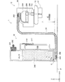
タンクユニット50の詳細構成を説明する前に、理解の容易のために、図2を用いてインクタンク30からサブタンク20にインクが供給される原理について説明する。図2は、インクタンク30からサブタンク20へのインク供給を説明するための図である。図2は、インクタンク30、ホース24、プリンター12の構成を模式的に示している。
Before explaining the detailed configuration of the
液体噴射システム1は、所定の水平面sf上に設置されている。液体噴射システム1の使用姿勢においては、Z軸負方向が鉛直下方向となる。インクタンク30は、液体導出部306と、液体収容室340と、空気収容室330と、液体注入口304と、栓部材302と、大気導入口317と、大気開放口318とを備える。
The
液体収容室340はインクを収容する。インクタンク30の液体導出部306と、サブタンク20の液体受入部202はホース24によって接続されている。これにより、液体収容室340のインクは、液体導出部306からホース24を介してサブタンク20に流通する。液体注入口304は、液体収容室340と連通している。液体注入口304には、栓部材302が脱着可能に取り付けられ、インクが液体注入口304から外部に漏れ出すことを防止している。
The
大気導入口317と大気開放口318は、外部からインクタンク30内部に大気を導入するための蛇行流路の両端部である。大気開放口318は、空気収容室330と連通している。空気収容室330は、狭小流路である連通部350によって液体収容室340と連通している。連通部350は、メニスカス(液面架橋)を形成可能な程度に流路断面積が小さい流路となっている。インクタンク30の使用状態においては、連通部350にメニスカスが形成される。
The
空気収容室330は所定容量の容積を有し、液体収容室340内の空気が温度変化等により膨張し、インクが連通部350を介して逆流した場合に、インクを貯留する。すなわち、インクタンク30は空気収容室330を備えることで、インクが逆流した場合でもインクが大気導入口317から外部に漏れ出す可能性を低減できる。
The
なお、インクタンク30にインクを注入する際の注入姿勢では、X軸負方向が鉛直下方向となるようにインクタンク30は所定の水平面sf上に設置される。すなわち、注入姿勢は、液体注入口304が鉛直上方向を向く姿勢である。なお、2以上のインクタンク30を配置(積層)したタンクユニット50の1つのインクタンク30にインクを注入する場合、タンクユニット50一体で姿勢を変化させるため、全てのインクタンク30が注入姿勢となる。注入姿勢で液体注入口304からインクを液体収容室340に注入した後に、液体注入口304を栓部材302で密封し使用姿勢にした場合、液体収容室340内の空気が膨張し、液体収容室340は負圧に維持される。また、空気収容室330は大気開放口318と連通することで大気圧に維持されている。
In addition, in the pouring posture when pouring ink into the
サブタンク20は、ポリスチレンやポリエチレン等の合成樹脂により成形されている。サブタンク20は、インク貯留室204と、インク流動路208と、フィルター206とを備える。インク流動路208には、キャリッジ16のインク供給針16aが挿入されている。フィルター206は、インクに異物等の不純物が混入していた場合に、その不純物を捕捉することで記録ヘッド17への不純物の流入を防止する。インク貯留室204のインクは、記録ヘッド17からの吸引によって、インク流動路208、インク供給針16aを流れて、記録ヘッド17に供給される。記録ヘッド17に供給されたインクは、ノズルを介して外部(印刷用紙)へ向かって噴射される。
The
使用姿勢において、メニスカスを形成する連通部350は、記録ヘッド17よりも低い位置になるように配置される。これにより、水頭差d1が発生する。なお、使用姿勢において、連通部350にメニスカスが形成された状態での水頭差d1を「定常時水頭差d1」とも呼ぶ。
In the use posture, the
インク貯留室204のインクが記録ヘッド17によって吸引されることで、インク貯留室204は所定の負圧以上となる。インク貯留室204が所定の負圧以上になると、液体収容室340のインクがホース24を介してインク貯留室204に供給される。すなわち、インク貯留室204には、記録ヘッド17に流出した量のインクが液体収容室340から自動的に補充されることになる。言い換えれば、インクタンク30内の空気収容室330と接するインク液面と、記録ヘッド(詳細にはノズル)との鉛直方向の高さの差によって発生する水頭差d1よりも、プリンター12側からの吸引力(負圧)がある程度大きくなることでインクが液体収容室340からインク貯留室204へ供給される。
As the ink in the
液体収容室340のインクが消費されると、空気収容室330の空気G(「気泡G」ともいう。)が連通部350を介して液体収容室340に導入される。これにより液体収容室340の液面は低下する。
When the ink in the
A−2.インクタンクの構成:
次に、図3及ぶ図4を用いてインクタンク30の構成を説明する。図3は、インクタンク30の第1の外観斜視図である。図4は、インクタンク30の第2の外観斜視図である。なお、図3及び図4には、栓部材302(図2)の図示は省略している。
A-2. Ink tank configuration:
Next, the configuration of the
図3に示すように、インクタンク30は、タンク本体32と、第1のフィルム34と、第2のフィルム322とを備える。タンク本体32は、ポリプロピレン等の合成樹脂により成形されている。また、タンク本体32は、半透明であり外部から内部のインクの量を確認できる。タンク本体32の形状は、一側面が開口した凹状形状である。タンク本体32の凹部には様々な形状のリブ362が形成されている。ここで、開口している一側面(開口を形成するタンク本体32の外枠を含む一側面)を開口側面370とも言う。また、図3及び図4に示すように、タンク本体32は、内部空間(例えば、液体収容室340)を挟んで開口側面370と対向する位置にある側面である対向壁面部372を備える。
As shown in FIG. 3, the
図3に示すように、第1のフィルム34は、ポリプロピレン等の合成樹脂により成形されており、透明状である。第1のフィルム34は熱溶着によって開口OPを覆うようにタンク本体32に貼り付けられる。具体的には、第1のフィルム34は、リブ362の端面、および、タンク本体32の外枠の端面に隙間が生じないように緻密に貼り付けられている。これにより複数の小部屋が形成されている。具体的には、主に、空気収容室330と液体収容室340と連通部350とが形成される。すなわち、タンク本体32と第1のフィルム34によって空気収容室330、液体収容室340、連通部350が形成されている。第1のフィルム34は、薄膜状であることから、硬質のタンク本体32よりも破損しやすい。なお、第1のフィルム34のタンク本体32への貼り付けは、熱溶着に限られず、例えば粘着剤を用いて貼り付けても良い。
As shown in FIG. 3, the
第2のフィルム322は、大気開放口318や大気開放口318と大気導入口317を含む蛇行流路の一部を覆うように、タンク本体32に貼り付けられている。
The
開口側面370近傍のタンク本体32には、開口側面370の外周を囲むように複数の突起部324が形成されている。突起部324は、タンク本体32から外側に向かって延びる突起形状である。本実施例では、突起部324は7つ(図3,4では3つのみ図示)形成されている。
A plurality of
図4に示すように、対向壁面部372は、開口OPの大きさよりも大きい壁面326と、壁面326の外周を取り囲み、壁面326の外周から立設された外周壁部325とを有する。なお、「外周を取り囲み」とは、壁面326の外周の半分以上を取り囲んでいることをいう。壁面326の外形形状と、開口側面370の外形形状と、開口OPの外形形状とは相似しており、壁面326の外周は、開口側面370の外周及び開口OPの外周よりも大きい。
As shown in FIG. 4, the opposing
対向壁面部372は、壁面326と外周壁部325によってインクタンク30の外側から見た場合に凹状形状をしている。詳細には、対向壁面部372は、対向壁面部372を挟んで液体収容室340とは反対の側(Y軸負方向側)から見た場合に凹状形状である。外周壁部325には複数の孔部325aが形成されている。本実施例では、孔部325aの個数は、突起部324の形成個数と対応している。すなわち、孔部325aは外周壁部325に7箇所形成されている。複数のインクタンク30を積層してタンクユニット50が形成される場合、1のインクタンク30の突起部324が、隣り合う他のインクタンク30の孔部325aに嵌め込まれることで、隣り合うインクタンク30同士が一体となる。タンク本体32は外力によって多少の弾性変形が可能であることから、突起部324と孔部325aの嵌合を解除し、組み立てられ一体となった2以上のインクタンク30を分解できる。ここで、突起部324と孔部325aによって、嵌合ユニット328(図4)を構成する。
The opposing
また、タンクユニット50が形成される場合、ある1つのインクタンク30の第1のフィルム34が、隣り合う他のインクタンク30の対向壁面部372の凹部327に入り込む。言い換えれば、ある1つのインクタンク30の第1のフィルム34の外周が外周壁部325によって取り囲まれる。ここで、「取り囲まれる」とは第1のフィルム34の外周の半分以上が取り囲まれていることをいう。これにより、第1のフィルム34が破損する可能性を低減し、液体収容室340のインクが外部へ漏れ出す可能性を低減できる。
When the
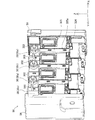
A−3.タンクユニットの構成:
図5は、タンクユニット50の分解斜視図である。なお、図5では、上面ケース54及び底面ケースの図示は省略している。また、インクタンク30について、各インクタンク30を区別して用いる場合は、符号30p,30q,30r,30sを用いる。
A-3. Tank unit configuration:
FIG. 5 is an exploded perspective view of the
複数のインクタンク30は、一列に配置される。具体的には、複数のインクタンク30は、開口側面370と対向壁面部372が対向する方向(Y軸方向)に一列に配置される。複数のインクタンク30を配置する際には、1のインクタンク30の突起部324が隣り合う他のインクタンク30の孔部325aに嵌め合わされる。また、1のインクタンク30の開口側面370側が隣り合う他のインクタンク30の対向壁面部372の凹部327に入り込むように配置され、1のインクタンク30の第1のフィルム34が他のインクタンク30の対向壁面部372によって保護される。
The plurality of
一列に配置されたインクタンク30の片側の端に位置するインクタンク30pの第1のフィルム34は、他のインクタンク30q,30r,30sにより覆われていない。しかしながら、インクタンク30pの開口側面370は第1の側面ケース56により覆わる。これにより、インクタンク30pの第1のフィルム34が保護される。ここで、インクタンク30pが課題を解決するための手段に記載の「露出液体収容容器」に相当する。
The
また、1のインクタンク30の液体注入口304を塞ぐ栓部材302と、隣り合う他のインクタンク30の液体注入口304を塞ぐ栓部材302とは連結部材303によって連結されている。すなわち、2つの栓部材302は連結部材303によって分離できないように一体に構成されている。あるインクタンク30にインクを注入(補充)する際に栓部材302(「対象栓部材302」ともいう。)を液体注入口304から取り外したとしても、対象栓部材302は隣り合う他のインクタンク30の栓部材302(「隣接栓部材302」ともいう。)に連結されている。ここで、隣接栓部材302は、他のインクタンク30の液体注入口304に取り付けられていることから、対象栓部材302は隣接栓部材302の近傍に位置することになる。よって、利用者は取り外した栓部材302を紛失する可能性を低減できる。
Further, the
図6は、タンクユニット50の外観斜視図である。なお、図6では上面ケース54及び底面ケースの図示は省略している。図6に示すように、1のインクタンク30の孔部325aに隣り合う他のインクタンク30の突起部324が嵌め合わされている。
FIG. 6 is an external perspective view of the
このように上記実施例では、各インクタンク30は、一側面が開口したタンク本体32の一側面に第1のフィルム34を貼り付けることで液体収容室340等の内部空間を形成している。よって、タンク本体32に硬質の蓋部材を振動溶着する場合に比べ、インクタンク30内部の気密性を確保しつつ内部空間を容易に形成することができる。また、インクタンク30の内部にタンク本体32の削りカス等の不純物が混入する可能性を低減できる。また、第1のフィルム34は、隣り合うインクタンク30のタンク本体32により覆われることで保護されているため、第1のフィルム34が破れて内部からインクが漏れ出す可能性を低減できる。また、硬質の部材同士を振動溶着し、インクタンクを形成する場合に比べ、インクタンクの積層方向(配列方向)の大きさをコンパクトにできる。これにより、複数のインクタンク30を積層したタンクユニット50を小型化できる。
Thus, in the above embodiment, each
また、突起部324と孔部325aとによって2以上のインクタンク30を容易に組み立てて一体とできると共に、一体としたインクタンク30がバラバラになる可能性を低減できる。また、一体とした2以上の液体収容容器を容易に分解できる。よって、プリンター12に用いられるインク色の数や仕様に応じて、タンクユニット50はインクタンク30の配置数を容易に変更できる。
In addition, the two or
B.変形例:
なお、上記実施例における構成要素の中の、特許請求の範囲の独立項に記載した要素以外の要素は、付加的な要素であり、適宜省略可能である。また、本発明の上記実施例や実施形態に限られるものではなく、その要旨を逸脱しない範囲において種々の形態において実施することが可能であり、例えば次のような変形も可能である。
B. Variations:
In addition, elements other than the elements described in the independent claims of the claims in the constituent elements in the above-described embodiments are additional elements and can be omitted as appropriate. Further, the present invention is not limited to the above-described examples and embodiments, and can be implemented in various forms without departing from the gist thereof. For example, the following modifications are possible.
B−1.第1変形例:
上記実施例では、対向壁面部372は外周壁部325を備えていたが(図4)、備えていなくても良い。すなわち、2以上のインクタンク30が配置された場合に、対向壁面部372は、隣り合うインクタンク30の第1のフィルム34の表面を覆うことが可能な形状であれば良い。このようにしても、上記実施例と同様に、1のインクタンク30の第1のフィルム34を隣り合う他のインクタンク30の対向壁面部372(詳細には壁面326)によって覆うことで保護できる。
B-1. First modification:
In the above-described embodiment, the opposing
B−2.第2変形例:
上記実施例では、インクタンク30は突起部324と孔部325aとを備える嵌合ユニット328を有していたが、省略可能である。このようにしても、上記実施例と同様に、1のインクタンク30の第1のフィルム34を隣り合う他のインクタンク30の対向壁面部372によって覆うことで保護できる。
B-2. Second modification:
In the above embodiment, the
B−3.第3変形例:
上記実施例では、液体収容容器としてプリンター12に用いられるインクタンク30及びタンクユニット50を例に説明を行ったが、これに限定されるものではなく、例えば液晶ディスプレー等の色材噴射ヘッドを備えた装置、有機ELディスプレー、面発光ディスプレー(FED)等の電極形成に用いられる電極材(導電ペースト)噴射ヘッドを備えた装置、バイオチップ製造に用いられる生体有機物噴射ヘッドを備えた装置、精密ピペットとしての試料噴射ヘッドを備えた装置、捺染装置やマイクロディスペンサ等の液体噴射装置の外部から液体を液体噴射装置に供給可能な液体収容容器及び2以上の液体収容容器を一列に配置したタンクユニットに本発明は適用できる。上記の各種の液体噴射装置に液体収容容器を使用する際には、各種の液体噴射装置が噴射する液体の種類に応じた液体(色材,導電ペースト,生体有機物等)を、液体収容容器内部に収容すれば良い。また、各種液体噴射装置と各種液体噴射装置に用いるタンクユニットを備える液体噴射システムとしても本発明は適用可能である。
B-3. Third modification:
In the above embodiment, the
1…液体噴射システム
10…ケース
12…プリンター
13…用紙給紙部
14…用紙排出部
16…キャリッジ
16a…インク供給針
17…記録ヘッド
20…サブタンク
20Bk…サブタンク
20Ma…サブタンク
20Cn…サブタンク
20Yw…サブタンク
24…ホース(チューブ)
30…液体収容容器(インクタンク)
32…タンク本体
34…第1のフィルム
50…タンクユニット
54…上面ケース
56…第1の側面ケース
58…第2の側面ケース
202…液体受入部
204…インク貯留室
206…フィルター
208…インク流動路
302…栓部材
303…連結部材
304…液体注入口
306…液体導出部
317…大気導入口
318…大気開放口
322…第2のフィルム
324…突起部
325…外周壁部
325a…孔部
326…壁面
327…凹部
328…嵌合ユニット
330…空気収容室
340…液体収容室
350…連通部
362…リブ
370…開口側面
372…対向壁面部
G…空気(気泡)
OP…開口
sf…水平面
DESCRIPTION OF
30 ... Liquid container (ink tank)
DESCRIPTION OF
OP ... Opening sf ... Horizontal plane
Claims (6)
1列に配置された2以上の液体収容容器を備え、
前記各液体収容容器は、
一側面が開口した凹状形状の容器本体と前記開口を塞ぐフィルムとによって形成された前記液体を収容するための液体収容室を、有し、
前記容器本体は、
前記液体収容室を挟んで前記フィルムと対向する対向壁面部であって、前記開口よりも大きい壁面を有する対向壁面部を有し、
1の前記液体収容容器の前記フィルムが、隣り合う他の前記液体収容容器の前記対向壁面部によって覆われるように、前記2以上の液体収容容器が配置され、
前記各液体収容容器は、さらに、
前記液体収容室に液体を注入するための液体注入口と、
前記液体注入口を塞ぐための栓部材であって、前記液体注入口に脱着可能に取り付けられる栓部材と、を有する、タンクユニット。 A tank unit for supplying liquid to the liquid ejecting apparatus from the outside of the liquid ejecting apparatus,
Comprising two or more liquid containers arranged in a row;
Each of the liquid containers is
A liquid storage chamber for storing the liquid formed by a concave container body having one side opened and a film closing the opening;
The container body is
An opposing wall surface portion facing the film across the liquid storage chamber, and having an opposing wall surface portion having a wall surface larger than the opening;
The two or more liquid storage containers are arranged so that the film of the one liquid storage container is covered by the opposing wall surface portion of the other adjacent liquid storage container ;
Each of the liquid storage containers further includes
A liquid inlet for injecting liquid into the liquid storage chamber;
A tank unit comprising: a plug member for closing the liquid inlet, the plug member being detachably attached to the liquid inlet .
1の前記液体収容容器の前記栓部材と、隣り合う他の前記液体収容容器の前記栓部材とは連結部材により連結されている、タンクユニット。 The tank unit, wherein the plug member of one of the liquid storage containers and the plug member of another adjacent liquid storage container are connected by a connection member.
前記各液体収容容器は、さらに、 Each of the liquid storage containers further includes
隣り合う前記液体収容容器との間で、取り付け、取り外しを行うための嵌合ユニットを有し、 A fitting unit for attaching and detaching between the adjacent liquid storage containers,
前記嵌合ユニットは、 The fitting unit is
突起部と、 A protrusion,
隣り合う前記液体収容容器の前記突起部が嵌め込まれる孔部と、を含む、タンクユニット。 A tank unit including the hole into which the protrusion of the adjacent liquid container is fitted.
上面ケースと、 A top case,
底面ケースと、 A bottom case,
前記2以上の液体収容容器を挟んで第1の側面ケースと、 A first side case sandwiching the two or more liquid storage containers;
前記第1の側面ケースとは反対の側に配置された第2の側面ケースと、をさらに備え、A second side case disposed on the opposite side of the first side case, and
前記上面ケースと、前記第1の側面ケースと、前記第2の側面ケースと、前記底面ケー The top case, the first side case, the second side case, and the bottom case
スとによって形成される内部空間に前記2以上の液体収容容器が配置されている、タンクA tank in which the two or more liquid storage containers are arranged in an internal space formed by
ユニット。unit.
請求項1乃至請求項4のいずれか1項に記載のタンクユニットと、 The tank unit according to any one of claims 1 to 4,
対象物に前記液体を噴射するためのヘッドを有する液体噴射装置と、 A liquid ejecting apparatus having a head for ejecting the liquid onto an object;
前記タンクユニットと前記液体噴射装置とを接続し、前記液体収容室に収容されている前記液体を前記液体噴射装置に流通させる流通管と、を備える、液体噴射システム。 A liquid ejecting system comprising: a circulation pipe that connects the tank unit and the liquid ejecting apparatus and causes the liquid ejecting apparatus to circulate the liquid stored in the liquid storage chamber.
前記液体噴射装置は、プリンターであり、 The liquid ejecting apparatus is a printer;
前記液体収容室に収容される前記液体はインクである、液体噴射システム。 The liquid ejecting system, wherein the liquid stored in the liquid storage chamber is ink.
Priority Applications (1)
| Application Number | Priority Date | Filing Date | Title |
|---|---|---|---|
| JP2013251942A JP5621902B2 (en) | 2013-12-05 | 2013-12-05 | Tank unit, liquid ejection system with tank unit |
Applications Claiming Priority (1)
| Application Number | Priority Date | Filing Date | Title |
|---|---|---|---|
| JP2013251942A JP5621902B2 (en) | 2013-12-05 | 2013-12-05 | Tank unit, liquid ejection system with tank unit |
Related Parent Applications (1)
| Application Number | Title | Priority Date | Filing Date |
|---|---|---|---|
| JP2013152189A Division JP5429425B2 (en) | 2013-07-23 | 2013-07-23 | Tank unit, liquid ejection system with tank unit |
Related Child Applications (1)
| Application Number | Title | Priority Date | Filing Date |
|---|---|---|---|
| JP2014194549A Division JP2015027807A (en) | 2014-09-25 | 2014-09-25 | Tank unit and liquid ejection system with the same |
Publications (3)
| Publication Number | Publication Date |
|---|---|
| JP2014040110A JP2014040110A (en) | 2014-03-06 |
| JP2014040110A5 JP2014040110A5 (en) | 2014-04-17 |
| JP5621902B2 true JP5621902B2 (en) | 2014-11-12 |
Family
ID=50392784
Family Applications (1)
| Application Number | Title | Priority Date | Filing Date |
|---|---|---|---|
| JP2013251942A Expired - Fee Related JP5621902B2 (en) | 2013-12-05 | 2013-12-05 | Tank unit, liquid ejection system with tank unit |
Country Status (1)
| Country | Link |
|---|---|
| JP (1) | JP5621902B2 (en) |
Cited By (4)
| Publication number | Priority date | Publication date | Assignee | Title |
|---|---|---|---|---|
| US10226932B2 (en) | 2017-01-31 | 2019-03-12 | Brother Kogyo Kabushiki Kaisha | Supply apparatus |
| US10583661B2 (en) | 2016-03-31 | 2020-03-10 | Brother Kogyo Kabushiki Kaisha | Tank and liquid consuming apparatus including the same |
| US10611163B2 (en) | 2016-03-31 | 2020-04-07 | Brother Kogyo Kabushiki Kaisha | Tank and liquid consuming apparatus including the same |
| US10618299B2 (en) | 2016-03-31 | 2020-04-14 | Brother Kogyo Kabushiki Kaisha | Tank set and liquid-consuming apparatus |
Families Citing this family (2)
| Publication number | Priority date | Publication date | Assignee | Title |
|---|---|---|---|---|
| JP6604021B2 (en) * | 2015-04-16 | 2019-11-13 | セイコーエプソン株式会社 | Ink supply system |
| JP7248165B2 (en) * | 2018-03-12 | 2023-03-29 | ブラザー工業株式会社 | system |
Family Cites Families (10)
| Publication number | Priority date | Publication date | Assignee | Title |
|---|---|---|---|---|
| JP2003231275A (en) * | 2002-02-07 | 2003-08-19 | Ricoh Co Ltd | Pressure adjusting mechanism of inkjet head section and inkjet printer using the same |
| CN2700105Y (en) * | 2003-10-14 | 2005-05-18 | 珠海天威飞马打印耗材有限公司 | Combinable continuous ink supply container |
| CN2744512Y (en) * | 2004-06-15 | 2005-12-07 | 珠海纳思达电子科技有限公司 | Self-contained integrated printer print cartridges with ink bag |
| US7810916B2 (en) * | 2005-09-29 | 2010-10-12 | Brother Kogyo Kabushiki Kaisha | Ink cartridges |
| JP4341688B2 (en) * | 2006-04-12 | 2009-10-07 | セイコーエプソン株式会社 | Liquid container |
| JP4389233B2 (en) * | 2007-04-09 | 2009-12-24 | セイコーエプソン株式会社 | Liquid container |
| US8192003B2 (en) * | 2007-12-28 | 2012-06-05 | Seiko Epson Corporation | Liquid container and liquid consuming apparatus |
| JPWO2009116298A1 (en) * | 2008-03-21 | 2011-07-21 | セイコーエプソン株式会社 | Liquid container |
| JP2010023247A (en) * | 2008-07-15 | 2010-02-04 | Seiko Epson Corp | Liquid supplying system and manufacturing method therefor |
| JP2010100009A (en) * | 2008-10-27 | 2010-05-06 | Canon Inc | Ink cartridge and sealing member |
-
2013
- 2013-12-05 JP JP2013251942A patent/JP5621902B2/en not_active Expired - Fee Related
Cited By (8)
| Publication number | Priority date | Publication date | Assignee | Title |
|---|---|---|---|---|
| US10583661B2 (en) | 2016-03-31 | 2020-03-10 | Brother Kogyo Kabushiki Kaisha | Tank and liquid consuming apparatus including the same |
| US10611163B2 (en) | 2016-03-31 | 2020-04-07 | Brother Kogyo Kabushiki Kaisha | Tank and liquid consuming apparatus including the same |
| US10618299B2 (en) | 2016-03-31 | 2020-04-14 | Brother Kogyo Kabushiki Kaisha | Tank set and liquid-consuming apparatus |
| US11040543B2 (en) | 2016-03-31 | 2021-06-22 | Brother Kogyo Kabushiki Kaisha | Tank and liquid consuming apparatus including the same |
| US11279140B2 (en) | 2016-03-31 | 2022-03-22 | Brother Kogyo Kabushiki Kaisha | Tank set and liquid-consuming apparatus |
| US11584136B2 (en) | 2016-03-31 | 2023-02-21 | Brother Kogyo Kabushiki Kaisha | Tank set and liquid-consuming apparatus |
| US10226932B2 (en) | 2017-01-31 | 2019-03-12 | Brother Kogyo Kabushiki Kaisha | Supply apparatus |
| US10710373B2 (en) | 2017-01-31 | 2020-07-14 | Brother Kogyo Kabushiki Kaisha | Supply apparatus |
Also Published As
| Publication number | Publication date |
|---|---|
| JP2014040110A (en) | 2014-03-06 |
Similar Documents
| Publication | Publication Date | Title |
|---|---|---|
| JP5327168B2 (en) | Tank unit, liquid ejection system with tank unit | |
| JP5429425B2 (en) | Tank unit, liquid ejection system with tank unit | |
| JP5691307B2 (en) | Liquid container and liquid ejection system | |
| JP5644279B2 (en) | Liquid container and liquid ejection system | |
| JP5454398B2 (en) | Liquid container, tank unit, and liquid ejection system | |
| JP5691308B2 (en) | Liquid container and liquid ejection system | |
| JP5621902B2 (en) | Tank unit, liquid ejection system with tank unit | |
| JP5862812B2 (en) | Liquid container and liquid ejection system | |
| JP5776242B2 (en) | Cap, liquid container, and liquid ejection system | |
| JP2015027807A (en) | Tank unit and liquid ejection system with the same | |
| US9636917B2 (en) | Liquid supply unit | |
| JP6311778B2 (en) | Liquid container and liquid ejection system | |
| JP6048518B2 (en) | Liquid container and liquid ejection system |
Legal Events
| Date | Code | Title | Description |
|---|---|---|---|
| A521 | Request for written amendment filed |
Free format text: JAPANESE INTERMEDIATE CODE: A523 Effective date: 20140106 |
|
| A621 | Written request for application examination |
Free format text: JAPANESE INTERMEDIATE CODE: A621 Effective date: 20140106 |
|
| A521 | Request for written amendment filed |
Free format text: JAPANESE INTERMEDIATE CODE: A523 Effective date: 20140212 |
|
| A871 | Explanation of circumstances concerning accelerated examination |
Free format text: JAPANESE INTERMEDIATE CODE: A871 Effective date: 20140212 |
|
| A975 | Report on accelerated examination |
Free format text: JAPANESE INTERMEDIATE CODE: A971005 Effective date: 20140403 |
|
| A131 | Notification of reasons for refusal |
Free format text: JAPANESE INTERMEDIATE CODE: A131 Effective date: 20140430 |
|
| TRDD | Decision of grant or rejection written | ||
| A01 | Written decision to grant a patent or to grant a registration (utility model) |
Free format text: JAPANESE INTERMEDIATE CODE: A01 Effective date: 20140826 |
|
| A61 | First payment of annual fees (during grant procedure) |
Free format text: JAPANESE INTERMEDIATE CODE: A61 Effective date: 20140908 |
|
| R150 | Certificate of patent or registration of utility model |
Ref document number: 5621902 Country of ref document: JP Free format text: JAPANESE INTERMEDIATE CODE: R150 |
|
| S531 | Written request for registration of change of domicile |
Free format text: JAPANESE INTERMEDIATE CODE: R313531 |
|
| R350 | Written notification of registration of transfer |
Free format text: JAPANESE INTERMEDIATE CODE: R350 |
|
| LAPS | Cancellation because of no payment of annual fees |