JP7183222B2 - Liquid storage container and recording device - Google Patents
Liquid storage container and recording device Download PDFInfo
- Publication number
- JP7183222B2 JP7183222B2 JP2020139534A JP2020139534A JP7183222B2 JP 7183222 B2 JP7183222 B2 JP 7183222B2 JP 2020139534 A JP2020139534 A JP 2020139534A JP 2020139534 A JP2020139534 A JP 2020139534A JP 7183222 B2 JP7183222 B2 JP 7183222B2
- Authority
- JP
- Japan
- Prior art keywords
- side wall
- liquid
- liquid storage
- ink
- storage chamber
- Prior art date
- Legal status (The legal status is an assumption and is not a legal conclusion. Google has not performed a legal analysis and makes no representation as to the accuracy of the status listed.)
- Active
Links
Images


Description
本発明は、液体収容容器及び記録装置に関する。 The present invention relates to a liquid container and a recording device.
従来、インクを吐出する記録ヘッドで消費されるインクを収容可能な液体収容容器(本明細書ではインクタンクとも言う)が知られている。インクタンクは一般に、インクを収容するためのインク収容室と、該収容室内から記録ヘッドにインクを供給するためのインク供給口とを備える。このような構成を有するインクタンクとして、例えば、特許文献1に記載のものが存在する。 2. Description of the Related Art Conventionally, a liquid storage container (also referred to as an ink tank in this specification) capable of storing ink consumed by a print head that ejects ink is known. An ink tank generally includes an ink containing chamber for containing ink and an ink supply port for supplying ink from the containing chamber to the print head. An ink tank having such a configuration is disclosed, for example, in Japanese Unexamined Patent Application Publication No. 2002-200010.
記録装置で使用されるインクには、例えば顔料インクのように凝集などによって色材が沈降し易いものが存在する。このようなインクを、特許文献1に記載のインクタンクに収容して用いる場合、インク収容室内において高濃度成分が沈降することで濃度に偏りが生じ、それによって、記録する画像に濃度むらが発生する恐れがある。 Among the inks used in the printing apparatus, there are inks, such as pigment inks, in which the colorant tends to settle due to aggregation or the like. When such ink is stored in the ink tank described in Patent Document 1 and used, the high-concentration component settles in the ink storage chamber, resulting in an uneven density, which causes density unevenness in the recorded image. there is a risk of
本発明の一実施形態は、液体を収容する液体収容室と、前記液体収容室へ液体を注入するための注入部と、前記液体収容室に収容される液体を記録ヘッドへ供給するための液体供給口と、前記液体収容室を仕分ける仕切り板と、を有し、前記液体収容室の第1の側壁および前記第1の側壁と対向する第2の側壁と交差する第1方向において前記注入部と前記液体供給口は離れて配置され、前記仕切り板は、前記第1の側壁と前記第2の側壁をつなぐ前記液体収容室の第3の側壁および前記第3の側壁と対向し、前記第1の側壁と前記第2の側壁をつなぐ前記液体収容室の第4の側壁と接触するように配置され、複数の前記仕切り板が各々前記第1方向に延在するように設けられ、かつ前記複数の仕切り板各々の前記第1方向における一方の端部が別の前記仕切り板と接触せず、かつ、前記第1の側壁と接触しないように配置され、前記複数の仕切り板のうち、少なくとも1つに切り欠きが形成されていることを特徴とする液体収容容器である。 An embodiment of the present invention includes a liquid storage chamber for storing liquid, an injection section for injecting liquid into the liquid storage chamber, and a liquid for supplying the liquid stored in the liquid storage chamber to a print head. The injection part has a supply port and a partition plate for dividing the liquid storage chamber, and is arranged in a first direction intersecting a first side wall of the liquid storage chamber and a second side wall facing the first side wall. and the liquid supply port are arranged apart from each other, and the partition plate faces the third side wall and the third side wall of the liquid storage chamber connecting the first side wall and the second side wall, A plurality of partition plates are arranged to contact a fourth side wall of the liquid storage chamber connecting one side wall and the second side wall, each extending in the first direction, and One end of each of the plurality of partition plates in the first direction is arranged so as not to contact another partition plate and not to contact the first side wall , and at least one of the plurality of partition plates The liquid storage container is characterized by having a notch formed on one side .
本発明により、供給する記録用液体(インク)の濃度をより均一にすることが可能となり、良好な画質の画像を印刷できる。 According to the present invention, it is possible to make the density of the supplied recording liquid (ink) more uniform, and to print an image of good image quality.
[実施例1]
以下、本発明の実施形態について、添付図面を参照して詳細に説明する。なお、各図面を通して、同一の要素には同一の符号を付与する。
[Example 1]
BEST MODE FOR CARRYING OUT THE INVENTION Hereinafter, embodiments of the present invention will be described in detail with reference to the accompanying drawings. In addition, the same code|symbol is provided to the same element through each drawing.
<記録装置の構成>
本実施例では、記録装置(プリンタ)として、シリアル型のインクジェット記録装置(以下「記録装置」と略記する)を例に挙げて説明する。
<Configuration of recording device>
In this embodiment, a serial type ink jet printing apparatus (hereinafter abbreviated as "printing apparatus") will be described as an example of a printing apparatus (printer).
図1は、実施例1における記録装置の要部の内部構成を示す斜視図である。なお、説明のために、図1に示すように、主走査方向がx軸方向、副走査方向がy軸方向、x軸およびy軸に直行する方向がz軸方向となるように座標軸を設定する。 FIG. 1 is a perspective view showing the internal configuration of the main part of the recording apparatus according to the first embodiment. For the sake of explanation, as shown in FIG. 1, the coordinate axes are set such that the main scanning direction is the x-axis direction, the sub-scanning direction is the y-axis direction, and the direction orthogonal to the x-axis and the y-axis is the z-axis direction. do.
図1に示すように、記録装置11は、記録部であるキャリッジ12に保持された記録ヘッド13と、インクタンク15から記録ヘッド13へ記録用液体(即ちインク)を供給するインク供給経路14とを備える。また、記録装置11は、シート(記録媒体)を給紙・搬送する構成要素として、給紙ローラと、搬送ローラ16と、排紙ローラと、メインシャーシと、タイミングベルトと、キャリッジモータ204とを備える。
As shown in FIG. 1, the
キャリッジ12はメインシャーシに支持されながら、タイミングベルトを介してキャリッジモータ204から駆動力を受け、記録媒体の搬送方向と直交する主走査方向に沿って移動する。これにより、記録ヘッド13がキャリッジ12と共に主走査方向に沿って往復移動することができる。
While being supported by the main chassis, the
キャリッジ12の位置を検出するためのコードストリップがタイミングベルトと平行に張設されている。コードストリップには、例えば1インチ当たり150~280本のピッチでマーキングが形成されている。一方、キャリッジ12には、コードストリップを読み取るためのエンコードセンサが搭載されている。
A code strip for detecting the position of the
記録ヘッド13は、画像データに基づいて記録媒体へインクを吐出して画像を記録する。なお、記録媒体としては、インク滴を着弾させて画像を形成できるものであれば任意のものを使用してよい。例えば、紙、布、光ディスクラベル面、プラスチックシート、OHPシート、封筒など、種々の材質および形態のものを記録媒体として使用することができる。 The recording head 13 records an image by ejecting ink onto a recording medium based on image data. Note that any recording medium may be used as long as an image can be formed by making ink droplets land thereon. For example, various materials and forms such as paper, cloth, optical disk label surface, plastic sheet, OHP sheet, and envelope can be used as the recording medium.
また、記録装置11は、キャリッジ12の主走査方向における移動範囲内に設けられるメンテナンス部を備える。メンテナンス部は、記録ヘッド13に対して回復処理を行う回復ユニットを備え、記録ヘッド吐出部と対面可能なように配置されている。
The
回復ユニットは、記録ヘッド吐出部をキャッピングするキャップ部と、記録ヘッド吐出部をキャッピングした状態で強制的にインクを吸引して記録ヘッド吐出部内の残留気泡や増粘したインクを除去する吸引機構とを備える。回復ユニットによる回復処理が行われると、記録ヘッド13の機能が回復する。これにより、記録ヘッド13の吐出特性が維持される。
The recovery unit includes a cap section that caps the print head ejection section, and a suction mechanism that forcibly sucks ink while the print head ejection section is capped to remove residual air bubbles and thickened ink in the print head ejection section. Prepare. When recovery processing is performed by the recovery unit, the function of the
<液体収容容器の構成>
図2は、実施例1における液体収容容器(即ち図1のインクタンク15)の内部構造を示す斜視図である。なお、図2に示すように、図1と同様に座標軸を設定する。
<Structure of Liquid Container>
FIG. 2 is a perspective view showing the internal structure of the liquid storage container (that is, the
図2に示すように、インクタンク15の上部にインク注入口21が設けられ、インク注入口21には、取り外し可能なタンクキャップ22が取り付けられている。また、インク注入口21の下部には、インクを収容可能な液体収容室(即ちインク収容室)33が設けられ、さらにインク収容室33の下部には、通常は空気を収容するための空間であるバッファ室34が設けられている。
As shown in FIG. 2, an
インク収容室33の底壁がバッファ室34の天井壁の一部となるように、バッファ室34は、インクタンク15内部を区画して形成されている。
The
インク収容室33の底壁面の端部には液体供給口(即ちインク供給口)24が設けられており、インク収容室33は、インク供給口24およびインク流通路26を通じて不図示のチューブに接続され、インク供給経路14と連結している。
A liquid supply port (that is, an ink supply port) 24 is provided at the end of the bottom wall surface of the
インク供給口24とは離れた位置の底壁面の端部にはインクタンク15の外部と連通させるための空気供給口23が設けられており、空気供給口23はバッファ室34と連通し、インク収容室33はバッファ室34を介してインクタンク15の外部と連通している。かかる構成により、インクで満たされたインク収容室33にタンクキャップ22を取り付けることで実現される密閉された状態において、インク収容室33内のインクが消費された場合、外部の空気をインク収容室33内に導入することができる。また、かかる構成により、インク収容室33のインク液面上部の空間の空気が気圧変動や温度変化が原因で膨張した場合に、バッファ室34に押し出されたインクを貯留することができるので、インクタンク15の外部にインクが漏れ出ることを防ぐことができる。
An
図3は、実施例1における液体収容容器(インクタンク15)の正面図である。なお、図3に示すように、図1と同様に座標軸を設定する。 FIG. 3 is a front view of the liquid storage container (ink tank 15) according to the first embodiment. Incidentally, as shown in FIG. 3, coordinate axes are set in the same manner as in FIG.
図3に示すように、インクタンク15の前面部となる正面にはインク収容室33内に残存するインク量を指し示す指標31が形成されている。インクの液面は外から見えるので、ユーザは、インクの液面および指標31を見て、インク収容室33内に収容されているインク残量を確認することができる。
As shown in FIG. 3, an
図4(a)は、実施例1における液体収容容器(インクタンク15)を側面から見たときの内部構造を示す断面図である。なお、図4(a)に示すように、図1と同様に座標軸を設定する。 FIG. 4A is a cross-sectional view showing the internal structure of the liquid storage container (ink tank 15) in Example 1 when viewed from the side. As shown in FIG. 4A, coordinate axes are set in the same manner as in FIG.
図4(a)に示すように、インクタンク15は、インク収容室33を構成する第1側壁27および第2側壁28を備える。第1側壁27は、zx平面に平行に形成され、第2側壁28は、第1側壁27と対向するように形成される。つまり、第1側壁27および第2側壁28は、平行に形成される。従ってこのとき、第1側壁27と第2側壁28とのy軸方向における位置は異なる。
As shown in FIG. 4A, the
また、インクタンク15は、第1側壁27からxy平面に沿って第2側壁28の方に向かって延在する仕切り板(リブ)25を備える。仕切り板25により、インク収容室33は上部と下部とに区分けされており、また、区分けされたインク収容室間で連通路が形成されている。
The
ここで、インク供給口24は、y軸方向において第1側壁27近傍の位置に形成される。また、空気供給口23は、y軸方向において第2側壁28近傍の位置に形成される。
Here, the
本実施例では記録装置11で使用されるインクは顔料インクであると仮定して説明する。顔料インクは、時間とともに重力方向に顔料成分が沈降する性質を持っている。この性質により、本実施例におけるインク収容室33内で沈降した顔料成分は仕切り板25上面に沈降し、その後、空気供給口23付近に沈降するので、インク収容室33の底壁面上において空気供給口23付近の顔料濃度が最も高くなることとなる。従って、インク供給口24付近の顔料濃度が高くなることを防止できる。
In this embodiment, the ink used in the
また、インク収容室33のインク液面上部の空間の空気が気圧変動や温度変化が原因で膨張、或いは、収縮することや、印刷によりインクが消費されること等により、バッファ室34にインクが流出し、或いは、バッファ室34からインクが流入する。このようなインクの流出入により、空気供給口23付近の濃度が高いインクが撹拌されることとなる。
Also, the air in the space above the ink level in the
さらに、バッファ室34内にインクが無い場合は、印刷等でインクを消費するとバッファ室34から、空気が空気供給口23を介して、気泡としてインク収容室33に流入する(図4(b)参照)。これにより、インク収容室33内のインクが流動し、空気供給口23付近に沈降した濃度の高いインクが攪拌されることとなる。
Furthermore, when there is no ink in the
なお、本実施例は顔料インクを使用するものに限定されない。つまり、時間の経過に伴ってインクタンク内のインクの濃度に偏りが生じる任意のインクを使用するものに対して、本実施例を適用することができる。 Note that this embodiment is not limited to using pigment ink. In other words, this embodiment can be applied to any type of ink that causes uneven concentration of ink in the ink tank over time.
<空気供給口、および、インク供給口の位置関係>
図5を用いて空気供給口23およびインク供給口24を設ける位置について説明する。なお、図5(a)および図5(b)では、図1と同様に座標軸を設定する。
<Positional relationship between air supply port and ink supply port>
The positions where the
図5(a)に、インク供給口24の一配置例を示す。図5(a)はインク収容室33を上面から見たときの内部構成を示す模式図であり、理解を容易にするために仕切り板25を省略してその先端251のみ表示し、インク供給口24の形成位置を模式的に図示している。実際には、インク供給口24は、仕切り板25で区分けされるインク収容室33の下部に設けられるため、インク収容室33を上から見たときには視認できない。
FIG. 5A shows an arrangement example of the
図5(a)に示すように、仕切り板25の先端251は、y軸方向において第1側壁27と第2側壁28との間に位置している。このとき、インク供給口24は、y軸方向に関して仕切り板25の先端251よりも第1側壁27側の任意の位置(即ち、図中にシングルハッチングで示す範囲内の任意の位置)に形成可能である。
As shown in FIG. 5A, the
また図5(b)に、インク供給口24および空気供給口23の一配置例を示す。図5(b)はインク収容室33を上面から見たときの内部構成を示す模式図であり、理解を容易にするために、仕切り板25を省略してインク供給口24と空気供給口23との位置関係を模式的に図示している。
FIG. 5B shows an arrangement example of the
図5(b)に示すように、空気供給口23は、y軸方向においてインク供給口24よりも第2側壁側に位置している。このように、空気供給口23は、y軸方向に関してインク供給口24よりも第2側壁28側の任意の位置(クロスハッチングで示す範囲内の任意の位置)に形成可能である。
As shown in FIG. 5B, the
以上説明したように、本実施例により、インク収容室33内に収容されたインクの濃度の偏りを容易に解消でき、印刷時により均一な濃度のインクを供給することができる。
As described above, according to this embodiment, it is possible to easily eliminate uneven density of the ink stored in the
[実施例2]
実施例1では、液体収容容器(インクタンク)が1つの仕切り板(リブ)を備える場合について説明した。本実施例では、液体収容容器が複数の仕切り板を備える場合について説明する。ただし以下の説明において、実施例1と共通する内容については、説明を簡略化または割愛する。
[Example 2]
In the first embodiment, the case where the liquid container (ink tank) has one partition plate (rib) has been described. In this embodiment, a case where the liquid container includes a plurality of partition plates will be described. However, in the following description, the description of the contents common to the first embodiment is simplified or omitted.
<液体収容容器の内部構成>
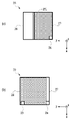
図6(a)は、実施例2における液体収容容器(インクタンク)の内部構造を示す斜視図である。なお、図6(a)に示すように、図1と同様に座標軸を設定する。
<Internal configuration of liquid storage container>
FIG. 6A is a perspective view showing the internal structure of the liquid storage container (ink tank) according to the second embodiment. Incidentally, as shown in FIG. 6A, coordinate axes are set in the same manner as in FIG.
図6(a)に示すように、本実施例におけるインクタンク15は、第1仕切り板(第1リブ)61と、第2仕切り板(第2リブ)62と、第3仕切り板(第3リブ)63とを備える。
As shown in FIG. 6A, the
第1仕切り板61は、第1側壁27からxy平面に沿って第2側壁28の方に向かって延在する。第2仕切り板62は、第1仕切り板61の上方に形成され、第2側壁28からxy平面に沿って第1側壁27の方に向かって延在する。第3仕切り板63は、第2仕切り板62の上方に形成され、第1側壁27からxy平面に沿って第2側壁28の方に向かって延在する。
The
上記の通り本実施例では、インク収容室内で、第1仕切り板61、第2仕切り板62、第3仕切り板63が鉛直方向(z軸方向)に重なるように配置される。このように複数の仕切り板を重なるように配置することで、仕切り板が1つのときよりも、インク収容室内におけるインク流路は長くなる。インク流路を長くすることで、高濃度のインクがインク収容室の底壁面に沈降することを抑制し、インク収容室の底壁面に高濃度のインクが集中することを防ぐことが可能となる。
As described above, in this embodiment, the
また、複数の仕切り板を鉛直方向(z軸方向)に重なるように配置することで、インク注入口21と、最上位に存在する仕切り板(図6(a)の例では第3仕切り板63)との間の距離が短くなる。これにより、インク注入時におけるインクの落下距離が短くなり、インク注入時における気泡の発生を抑制することが可能となる。
In addition, by arranging a plurality of partition plates so as to overlap in the vertical direction (z-axis direction), the
図6(b)に示すように、第1仕切り板61、第2仕切り板62、第3仕切り板63は夫々、切り欠きを備えていてもよい。第1仕切り板61の切り欠き64および第3仕切り板63の切り欠き66は、第1側壁27近傍に形成され、第2仕切り板62の切り欠き65は、第2側壁28近傍に形成される。このとき図6(b)に示すように、それぞれのxy座標における位置が異なるように、切り欠き64、切り欠き65、切り欠き66を形成することで、高濃度のインクがインク供給口24付近に沈降することを防いでいる。
As shown in FIG. 6B, each of the
切り欠き64によって第1側壁27近傍に発生する気泡を第1仕切り板61下面に滞留させずに上方に逃がすことができ、切り欠き65によって第2側壁28近傍に発生する気泡を第2仕切り板62下面に滞留させずに上方に逃がすことができる。このように、インク注入時やインク消費時などに生じる気泡を仕切り板下面に滞留させずに上部に逃がすことができる。従って、ユーザは、インクの液面および指標31を見て、正確なインク残量を確認することができる。
The
なお上述の例では、仕切り板が3つの場合について説明しているが、本実施例におけるインクタンク15は、複数の仕切り板を有していればよい。即ち、インク収容室の底壁面から上方(z軸正方向)に向かって、第1側壁27から第2側壁28の方に向かって延在する仕切り板と、第2側壁28から第1側壁27の方に向かって延在する仕切り板とが交互に出現するように形成されたインクタンクであればよい。
In the above example, the case where there are three partition plates is described, but the
15 インクタンク
24 インク供給口
25 仕切り板(リブ)
251 仕切り板(リブ)先端
27 第1側壁
28 第2側壁
33 インク収容室
15
251 partition plate (rib)
Claims (11)
前記液体収容室の第1の側壁および前記第1の側壁と対向する第2の側壁と交差する第1方向において前記注入部と前記液体供給口は離れて配置され、
前記仕切り板は、前記第1の側壁と前記第2の側壁をつなぐ前記液体収容室の第3の側壁および前記第3の側壁と対向し、前記第1の側壁と前記第2の側壁をつなぐ前記液体収容室の第4の側壁と接触するように配置され、
複数の前記仕切り板が各々前記第1方向に延在するように設けられ、かつ前記複数の仕切り板各々の前記第1方向における一方の端部が別の前記仕切り板と接触せず、かつ、前記第1の側壁と接触しないように配置され、
前記複数の仕切り板のうち、少なくとも1つに切り欠きが形成されていることを特徴とする液体収容容器。 a liquid storage chamber for storing liquid; an injection section for injecting liquid into the liquid storage chamber; a liquid supply port for supplying the liquid stored in the liquid storage chamber to a print head; and a partition plate for sorting the
the injection part and the liquid supply port are spaced apart in a first direction intersecting a first side wall of the liquid containing chamber and a second side wall facing the first side wall;
The partition plate faces a third side wall of the liquid storage chamber connecting the first side wall and the second side wall and the third side wall, and connects the first side wall and the second side wall. arranged to contact a fourth sidewall of the liquid storage chamber;
A plurality of partition plates are provided so as to extend in the first direction, and one end of each of the plurality of partition plates in the first direction does not contact another partition plate, and arranged so as not to contact the first sidewall ;
A liquid storage container , wherein a notch is formed in at least one of the plurality of partition plates .
前記液体収容室の第1の側壁および前記第1の側壁と対向する第2の側壁と交差する第1方向において前記注入部と前記液体供給口は離れて配置され、
前記仕切り板は、前記第1の側壁と前記第2の側壁をつなぐ前記液体収容室の第3の側壁および前記第3の側壁と対向し、前記第1の側壁と前記第2の側壁をつなぐ前記液体収容室の第4の側壁と接触するように配置され、
複数の前記仕切り板が各々前記第1方向に延在するように設けられ、かつ前記複数の仕切り板は、前記液体収容室から前記記録ヘッドへ液体を供給するときの重力方向の位置が異なるように配置され、
前記複数の仕切り板のうち、少なくとも1つに切り欠きが形成されていることを特徴とする液体収容容器。 a liquid storage chamber for storing liquid; an injection section for injecting liquid into the liquid storage chamber; a liquid supply port for supplying the liquid stored in the liquid storage chamber to a print head; and a partition plate for sorting the
the injection part and the liquid supply port are spaced apart in a first direction intersecting a first side wall of the liquid containing chamber and a second side wall facing the first side wall;
The partition plate faces a third side wall of the liquid storage chamber connecting the first side wall and the second side wall and the third side wall, and connects the first side wall and the second side wall. arranged to contact a fourth sidewall of the liquid storage chamber;
A plurality of partition plates are provided so as to extend in the first direction, and the plurality of partition plates have different positions in the gravitational direction when liquid is supplied from the liquid storage chamber to the recording head. is placed in
A liquid storage container , wherein a notch is formed in at least one of the plurality of partition plates .
液体を収容する液体収容室と、前記液体収容室へ液体を注入するための注入部と、前記液体収容室に収容される液体を前記記録ヘッドへ供給するための液体供給口と、前記液体収容室を仕分ける仕切り板と、を有する液体収容容器と、を有する記録装置であって、
前記液体収容室の第1の側壁および前記第1の側壁と対向する第2の側壁と交差する第1方向において前記注入部と前記液体供給口は離れて配置され、
前記仕切り板は、前記第1の側壁と前記第2の側壁をつなぐ前記液体収容室の第3の側壁および前記第3の側壁と対向し、前記第1の側壁と前記第2の側壁をつなぐ前記液体収容室の第4の側壁と接触するように配置され、
複数の前記仕切り板が各々前記第1方向に延在するように設けられ、かつ前記液体収容室から前記記録ヘッドへ液体を供給するときにおいて、前記複数の仕切り板の重力方向の位置が異なるように設けられ、
前記複数の仕切り板のうち、少なくとも1つに切り欠きが形成されていることを特徴とする記録装置。 a recording head for ejecting liquid onto a medium;
a liquid storage chamber for storing liquid; an injection section for injecting liquid into the liquid storage chamber; a liquid supply port for supplying the liquid stored in the liquid storage chamber to the recording head; A recording apparatus having a partition plate for sorting chambers and a liquid storage container having
the injection part and the liquid supply port are spaced apart in a first direction intersecting a first side wall of the liquid containing chamber and a second side wall facing the first side wall;
The partition plate faces a third side wall of the liquid storage chamber connecting the first side wall and the second side wall and the third side wall, and connects the first side wall and the second side wall. arranged to contact a fourth sidewall of the liquid storage chamber;
A plurality of partition plates are provided so as to extend in the first direction, and the positions of the plurality of partition plates in the gravitational direction are different when the liquid is supplied from the liquid storage chamber to the recording head. provided in
A recording apparatus , wherein a notch is formed in at least one of the plurality of partition plates .
Priority Applications (2)
| Application Number | Priority Date | Filing Date | Title |
|---|---|---|---|
| JP2020139534A JP7183222B2 (en) | 2020-08-20 | 2020-08-20 | Liquid storage container and recording device |
| JP2022136944A JP7414915B2 (en) | 2020-08-20 | 2022-08-30 | Liquid storage container and liquid discharge device |
Applications Claiming Priority (1)
| Application Number | Priority Date | Filing Date | Title |
|---|---|---|---|
| JP2020139534A JP7183222B2 (en) | 2020-08-20 | 2020-08-20 | Liquid storage container and recording device |
Related Parent Applications (1)
| Application Number | Title | Priority Date | Filing Date |
|---|---|---|---|
| JP2015213665A Division JP6752569B2 (en) | 2015-10-30 | 2015-10-30 | Recording device |
Related Child Applications (1)
| Application Number | Title | Priority Date | Filing Date |
|---|---|---|---|
| JP2022136944A Division JP7414915B2 (en) | 2020-08-20 | 2022-08-30 | Liquid storage container and liquid discharge device |
Publications (2)
| Publication Number | Publication Date |
|---|---|
| JP2020189496A JP2020189496A (en) | 2020-11-26 |
| JP7183222B2 true JP7183222B2 (en) | 2022-12-05 |
Family
ID=73454270
Family Applications (2)
| Application Number | Title | Priority Date | Filing Date |
|---|---|---|---|
| JP2020139534A Active JP7183222B2 (en) | 2020-08-20 | 2020-08-20 | Liquid storage container and recording device |
| JP2022136944A Active JP7414915B2 (en) | 2020-08-20 | 2022-08-30 | Liquid storage container and liquid discharge device |
Family Applications After (1)
| Application Number | Title | Priority Date | Filing Date |
|---|---|---|---|
| JP2022136944A Active JP7414915B2 (en) | 2020-08-20 | 2022-08-30 | Liquid storage container and liquid discharge device |
Country Status (1)
| Country | Link |
|---|---|
| JP (2) | JP7183222B2 (en) |
Cited By (1)
| Publication number | Priority date | Publication date | Assignee | Title |
|---|---|---|---|---|
| JP7347267B2 (en) | 2020-03-03 | 2023-09-20 | 三菱電機株式会社 | semiconductor manufacturing equipment |
Citations (9)
| Publication number | Priority date | Publication date | Assignee | Title |
|---|---|---|---|---|
| JP2005342992A (en) | 2004-06-02 | 2005-12-15 | Canon Inc | Ink tank for inkjet recording |
| CN201002392Y (en) | 2007-01-30 | 2008-01-09 | 孙荣华 | High capacity ink storing container |
| JP3155835U (en) | 2009-09-18 | 2009-12-03 | クオ−セン ワン アレックス | Refillable ink cartridge with side sealing |
| JP2010208264A (en) | 2009-03-12 | 2010-09-24 | Seiko Epson Corp | Liquid storing container |
| JP2011240705A (en) | 2011-07-28 | 2011-12-01 | Seiko Epson Corp | Liquid storage container, liquid jet system and liquid supply system |
| JP2014166710A (en) | 2013-02-28 | 2014-09-11 | Seiko Epson Corp | Liquid holding container |
| JP2015131434A (en) | 2014-01-14 | 2015-07-23 | セイコーエプソン株式会社 | Liquid storage container, liquid storage container unit, liquid injection system, and liquid injection device |
| JP2017030158A (en) | 2015-07-29 | 2017-02-09 | セイコーエプソン株式会社 | Liquid storage body, liquid jet system |
| JP2017071095A (en) | 2015-10-06 | 2017-04-13 | セイコーエプソン株式会社 | Liquid jet system, ventilation unit, and liquid supply device |
Family Cites Families (8)
| Publication number | Priority date | Publication date | Assignee | Title |
|---|---|---|---|---|
| JP3624948B2 (en) | 2001-04-03 | 2005-03-02 | セイコーエプソン株式会社 | ink cartridge |
| DE202005020053U1 (en) | 2005-07-04 | 2006-02-23 | Pelikan Hardcopy Production Ag | ink cartridge |
| JP2007044951A (en) | 2005-08-09 | 2007-02-22 | Canon Inc | Ink-jet recording head cartridge |
| CN2900170Y (en) | 2006-05-06 | 2007-05-16 | 珠海天威技术开发有限公司 | Ink box of ink jet printer |
| JP5966397B2 (en) | 2011-12-26 | 2016-08-10 | セイコーエプソン株式会社 | Program, storage medium, information processing apparatus, and printing system |
| JP6155556B2 (en) | 2012-05-31 | 2017-07-05 | セイコーエプソン株式会社 | Method for manufacturing liquid container |
| JP5958220B2 (en) * | 2012-09-14 | 2016-07-27 | セイコーエプソン株式会社 | Liquid container and liquid consumption apparatus |
| JP2015030234A (en) | 2013-08-06 | 2015-02-16 | セイコーエプソン株式会社 | Ink tank |
-
2020
- 2020-08-20 JP JP2020139534A patent/JP7183222B2/en active Active
-
2022
- 2022-08-30 JP JP2022136944A patent/JP7414915B2/en active Active
Patent Citations (9)
| Publication number | Priority date | Publication date | Assignee | Title |
|---|---|---|---|---|
| JP2005342992A (en) | 2004-06-02 | 2005-12-15 | Canon Inc | Ink tank for inkjet recording |
| CN201002392Y (en) | 2007-01-30 | 2008-01-09 | 孙荣华 | High capacity ink storing container |
| JP2010208264A (en) | 2009-03-12 | 2010-09-24 | Seiko Epson Corp | Liquid storing container |
| JP3155835U (en) | 2009-09-18 | 2009-12-03 | クオ−セン ワン アレックス | Refillable ink cartridge with side sealing |
| JP2011240705A (en) | 2011-07-28 | 2011-12-01 | Seiko Epson Corp | Liquid storage container, liquid jet system and liquid supply system |
| JP2014166710A (en) | 2013-02-28 | 2014-09-11 | Seiko Epson Corp | Liquid holding container |
| JP2015131434A (en) | 2014-01-14 | 2015-07-23 | セイコーエプソン株式会社 | Liquid storage container, liquid storage container unit, liquid injection system, and liquid injection device |
| JP2017030158A (en) | 2015-07-29 | 2017-02-09 | セイコーエプソン株式会社 | Liquid storage body, liquid jet system |
| JP2017071095A (en) | 2015-10-06 | 2017-04-13 | セイコーエプソン株式会社 | Liquid jet system, ventilation unit, and liquid supply device |
Cited By (1)
| Publication number | Priority date | Publication date | Assignee | Title |
|---|---|---|---|---|
| JP7347267B2 (en) | 2020-03-03 | 2023-09-20 | 三菱電機株式会社 | semiconductor manufacturing equipment |
Also Published As
| Publication number | Publication date |
|---|---|
| JP7414915B2 (en) | 2024-01-16 |
| JP2022169753A (en) | 2022-11-09 |
| JP2020189496A (en) | 2020-11-26 |
Similar Documents
| Publication | Publication Date | Title |
|---|---|---|
| CN109927414B (en) | Printing apparatus and liquid storage container | |
| JP5560673B2 (en) | Liquid storage tank, liquid discharge head unit, and image forming apparatus | |
| WO2016157901A1 (en) | Liquid supply device and liquid consuming device | |
| JP5176967B2 (en) | Ink cartridge and image forming apparatus | |
| JP7305404B2 (en) | Inkjet recording device and ink tank | |
| JP7414915B2 (en) | Liquid storage container and liquid discharge device | |
| JP6752569B2 (en) | Recording device | |
| JP2018039227A (en) | Inkjet printer | |
| JP6119338B2 (en) | Image recording device | |
| JPH08267775A (en) | Ink tank, ink jet unit and ink jet printer | |
| JP6961916B2 (en) | Inkjet printer | |
| US7396109B2 (en) | Inkjet printing system with high drop-weight yellow | |
| JP2000334975A (en) | Ink jet printer | |
| US20130127940A1 (en) | Liquid Ejecting Apparatus | |
| JP7225336B2 (en) | recording device | |
| JP7183240B2 (en) | recording device | |
| US11780236B2 (en) | Liquid ejecting apparatus and control method of liquid ejecting apparatus | |
| JP2019084694A (en) | cartridge | |
| JPH07125239A (en) | Ink tank unit, ink jet cartridge having the ink tank unit, and ink jet device having the ink jet cartridge | |
| JP6666052B2 (en) | Recording device | |
| JP7224945B2 (en) | inkjet printer | |
| JP6766222B2 (en) | Inkjet recording device | |
| JP2018094740A (en) | Recording head and head cleaning mechanism comprising the same as well as inkjet recording device | |
| JP2022184099A (en) | Recording device and recording head | |
| JP6296377B2 (en) | Liquid cartridge |
Legal Events
| Date | Code | Title | Description |
|---|---|---|---|
| A521 | Request for written amendment filed |
Free format text: JAPANESE INTERMEDIATE CODE: A523 Effective date: 20200918 |
|
| A621 | Written request for application examination |
Free format text: JAPANESE INTERMEDIATE CODE: A621 Effective date: 20200918 |
|
| A977 | Report on retrieval |
Free format text: JAPANESE INTERMEDIATE CODE: A971007 Effective date: 20210714 |
|
| A131 | Notification of reasons for refusal |
Free format text: JAPANESE INTERMEDIATE CODE: A131 Effective date: 20210720 |
|
| A521 | Request for written amendment filed |
Free format text: JAPANESE INTERMEDIATE CODE: A523 Effective date: 20210921 |
|
| A131 | Notification of reasons for refusal |
Free format text: JAPANESE INTERMEDIATE CODE: A131 Effective date: 20220111 |
|
| A521 | Request for written amendment filed |
Free format text: JAPANESE INTERMEDIATE CODE: A523 Effective date: 20220301 |
|
| A02 | Decision of refusal |
Free format text: JAPANESE INTERMEDIATE CODE: A02 Effective date: 20220531 |
|
| A521 | Request for written amendment filed |
Free format text: JAPANESE INTERMEDIATE CODE: A523 Effective date: 20220830 |
|
| C60 | Trial request (containing other claim documents, opposition documents) |
Free format text: JAPANESE INTERMEDIATE CODE: C60 Effective date: 20220830 |
|
| A911 | Transfer to examiner for re-examination before appeal (zenchi) |
Free format text: JAPANESE INTERMEDIATE CODE: A911 Effective date: 20220912 |
|
| C21 | Notice of transfer of a case for reconsideration by examiners before appeal proceedings |
Free format text: JAPANESE INTERMEDIATE CODE: C21 Effective date: 20220913 |
|
| TRDD | Decision of grant or rejection written | ||
| A01 | Written decision to grant a patent or to grant a registration (utility model) |
Free format text: JAPANESE INTERMEDIATE CODE: A01 Effective date: 20221025 |
|
| A61 | First payment of annual fees (during grant procedure) |
Free format text: JAPANESE INTERMEDIATE CODE: A61 Effective date: 20221122 |
|
| R151 | Written notification of patent or utility model registration |
Ref document number: 7183222 Country of ref document: JP Free format text: JAPANESE INTERMEDIATE CODE: R151 |