JP5836639B2 - Image forming apparatus - Google Patents
Image forming apparatus Download PDFInfo
- Publication number
- JP5836639B2 JP5836639B2 JP2011110619A JP2011110619A JP5836639B2 JP 5836639 B2 JP5836639 B2 JP 5836639B2 JP 2011110619 A JP2011110619 A JP 2011110619A JP 2011110619 A JP2011110619 A JP 2011110619A JP 5836639 B2 JP5836639 B2 JP 5836639B2
- Authority
- JP
- Japan
- Prior art keywords
- cartridge
- image forming
- forming apparatus
- mounting portion
- pull
- Prior art date
- Legal status (The legal status is an assumption and is not a legal conclusion. Google has not performed a legal analysis and makes no representation as to the accuracy of the status listed.)
- Expired - Fee Related
Links
Images


Classifications
-
- G—PHYSICS
- G03—PHOTOGRAPHY; CINEMATOGRAPHY; ANALOGOUS TECHNIQUES USING WAVES OTHER THAN OPTICAL WAVES; ELECTROGRAPHY; HOLOGRAPHY
- G03G—ELECTROGRAPHY; ELECTROPHOTOGRAPHY; MAGNETOGRAPHY
- G03G21/00—Arrangements not provided for by groups G03G13/00 - G03G19/00, e.g. cleaning, elimination of residual charge
- G03G21/16—Mechanical means for facilitating the maintenance of the apparatus, e.g. modular arrangements
- G03G21/18—Mechanical means for facilitating the maintenance of the apparatus, e.g. modular arrangements using a processing cartridge, whereby the process cartridge comprises at least two image processing means in a single unit
- G03G21/1839—Means for handling the process cartridge in the apparatus body
- G03G21/1842—Means for handling the process cartridge in the apparatus body for guiding and mounting the process cartridge, positioning, alignment, locks
- G03G21/1853—Means for handling the process cartridge in the apparatus body for guiding and mounting the process cartridge, positioning, alignment, locks the process cartridge being mounted perpendicular to the axis of the photosensitive member
-
- G—PHYSICS
- G03—PHOTOGRAPHY; CINEMATOGRAPHY; ANALOGOUS TECHNIQUES USING WAVES OTHER THAN OPTICAL WAVES; ELECTROGRAPHY; HOLOGRAPHY
- G03G—ELECTROGRAPHY; ELECTROPHOTOGRAPHY; MAGNETOGRAPHY
- G03G21/00—Arrangements not provided for by groups G03G13/00 - G03G19/00, e.g. cleaning, elimination of residual charge
- G03G21/16—Mechanical means for facilitating the maintenance of the apparatus, e.g. modular arrangements
- G03G21/1661—Mechanical means for facilitating the maintenance of the apparatus, e.g. modular arrangements means for handling parts of the apparatus in the apparatus
-
- G—PHYSICS
- G03—PHOTOGRAPHY; CINEMATOGRAPHY; ANALOGOUS TECHNIQUES USING WAVES OTHER THAN OPTICAL WAVES; ELECTROGRAPHY; HOLOGRAPHY
- G03G—ELECTROGRAPHY; ELECTROPHOTOGRAPHY; MAGNETOGRAPHY
- G03G21/00—Arrangements not provided for by groups G03G13/00 - G03G19/00, e.g. cleaning, elimination of residual charge
- G03G21/16—Mechanical means for facilitating the maintenance of the apparatus, e.g. modular arrangements
- G03G21/1604—Arrangement or disposition of the entire apparatus
- G03G21/1623—Means to access the interior of the apparatus
- G03G21/1633—Means to access the interior of the apparatus using doors or covers
-
- G—PHYSICS
- G03—PHOTOGRAPHY; CINEMATOGRAPHY; ANALOGOUS TECHNIQUES USING WAVES OTHER THAN OPTICAL WAVES; ELECTROGRAPHY; HOLOGRAPHY
- G03G—ELECTROGRAPHY; ELECTROPHOTOGRAPHY; MAGNETOGRAPHY
- G03G2215/00—Apparatus for electrophotographic processes
- G03G2215/01—Apparatus for electrophotographic processes for producing multicoloured copies
- G03G2215/0103—Plural electrographic recording members
- G03G2215/0119—Linear arrangement adjacent plural transfer points
- G03G2215/0122—Linear arrangement adjacent plural transfer points primary transfer to an intermediate transfer belt
- G03G2215/0125—Linear arrangement adjacent plural transfer points primary transfer to an intermediate transfer belt the linear arrangement being horizontal or slanted
- G03G2215/0132—Linear arrangement adjacent plural transfer points primary transfer to an intermediate transfer belt the linear arrangement being horizontal or slanted vertical medium transport path at the secondary transfer
-
- G—PHYSICS
- G03—PHOTOGRAPHY; CINEMATOGRAPHY; ANALOGOUS TECHNIQUES USING WAVES OTHER THAN OPTICAL WAVES; ELECTROGRAPHY; HOLOGRAPHY
- G03G—ELECTROGRAPHY; ELECTROPHOTOGRAPHY; MAGNETOGRAPHY
- G03G2221/00—Processes not provided for by group G03G2215/00, e.g. cleaning or residual charge elimination
- G03G2221/16—Mechanical means for facilitating the maintenance of the apparatus, e.g. modular arrangements and complete machine concepts
- G03G2221/1678—Frame structures
- G03G2221/1684—Frame structures using extractable subframes, e.g. on rails or hinges
-
- G—PHYSICS
- G03—PHOTOGRAPHY; CINEMATOGRAPHY; ANALOGOUS TECHNIQUES USING WAVES OTHER THAN OPTICAL WAVES; ELECTROGRAPHY; HOLOGRAPHY
- G03G—ELECTROGRAPHY; ELECTROPHOTOGRAPHY; MAGNETOGRAPHY
- G03G2221/00—Processes not provided for by group G03G2215/00, e.g. cleaning or residual charge elimination
- G03G2221/16—Mechanical means for facilitating the maintenance of the apparatus, e.g. modular arrangements and complete machine concepts
- G03G2221/18—Cartridge systems
- G03G2221/183—Process cartridge
Landscapes
- Physics & Mathematics (AREA)
- General Physics & Mathematics (AREA)
- Engineering & Computer Science (AREA)
- Computer Vision & Pattern Recognition (AREA)
- Electrophotography Configuration And Component (AREA)
Description
本発明は、複数のカートリッジを装置本体に取り外し可能に装着して、記録媒体に画像を形成する画像形成装置に関する。 The present invention is mounted removably a plurality of cartridges in the apparatus main body, to images forming apparatus that to form an image on a recording medium.
ここで、カラー電子写真画像形成装置とは、電子写真画像形成プロセスを用いて、記録媒体にカラー画像を形成するものである。そして、カラー電子写真画像形成装置の例としては、例えばカラー電子写真複写機、カラー電子写真プリンタ(例えばカラーレーザビームプリンタ、カラーLEDプリンタ等)、カラーファクシミリ装置及びカラーワードプロセッサ等が含まれる。 Here, the color electrophotographic image forming apparatus forms a color image on a recording medium using an electrophotographic image forming process. Examples of the color electrophotographic image forming apparatus include a color electrophotographic copying machine, a color electrophotographic printer (for example, a color laser beam printer, a color LED printer), a color facsimile apparatus, a color word processor, and the like.
また、記録媒体とは、電子写真画像形成装置によって画像が形成されるものであって、例えば、紙、OHPシート等が含まれる。 The recording medium is an image on which an image is formed by an electrophotographic image forming apparatus, and includes, for example, paper, an OHP sheet, and the like.
また、カートリッジとは、例えば、プロセスカートリッジ或いは現像カートリッジであって、電子写真画像形成装置の本体に取り外し可能に装着された状態で、記録媒体に画像を形成する画像形成プロセスに寄与するものである。ここで、前記プロセスカートリッジとは、プロセス手段としての、帯電手段、現像手段、クリーニング手段の少なくとも一つと電子写真感光体ドラムとを一体的にカートリッジ化して、前記本体に取り外し可能に装着されるものである。従って、プロセスカートリッジとは、プロセス手段としての現像手段と、前記電子写真感光体ドラムとを一体的にカートリッジ化して、電子写真画像形成装置の本体に取り外し可能に装着されるものも含まれる。また、プロセスカートリッジとは、プロセス手段としての、帯電手段、現像手段またはクリーニング手段と、前記電子写真感光体ドラムとを一体的にカートリッジ化して、前記本体に取り外し可能に装着されるものも含まれる。尚、電子写真感光体ドラムと現像手段とを一体的に有するプロセスカートリッジを所謂一体型と称する。また、電子写真感光体ドラムと現像手段以外のプロセス手段とを一体的に有するプロセスカートリッジを所謂分離型と称する。即ち、現像手段はプロセスカートリッジとは別の現像ユニットに設けて、この現像ユニットと対になって画像を形成するプロセスカートリッジを所謂分離型と称する。 The cartridge is, for example, a process cartridge or a developing cartridge, and contributes to an image forming process for forming an image on a recording medium in a state in which the cartridge is detachably attached to the main body of the electrophotographic image forming apparatus. . Here, the process cartridge is a cartridge in which at least one of charging means, developing means, and cleaning means as process means and an electrophotographic photosensitive drum are integrally formed, and is detachably mounted on the main body. It is. Therefore, the process cartridge includes a cartridge in which the developing means as the process means and the electrophotographic photosensitive drum are integrally formed and detachably attached to the main body of the electrophotographic image forming apparatus. In addition, the process cartridge includes a cartridge in which a charging unit, a developing unit or a cleaning unit as a process unit and the electrophotographic photosensitive drum are integrally formed and detachably mounted on the main body. . A process cartridge integrally including an electrophotographic photosensitive drum and developing means is referred to as a so-called integrated type. A process cartridge that integrally includes an electrophotographic photosensitive drum and process means other than the developing means is referred to as a so-called separation type. In other words, the developing unit is provided in a developing unit different from the process cartridge, and the process cartridge that forms an image with the developing unit is referred to as a so-called separation type.
ここで前記プロセスカートリッジは、使用者自身によって本体に対する着脱を行うことができる。そのため、装置本体のメンテナンスを容易に行うことができる。尚、前記プロセス手段は、前記電子写真感光体ドラムに作用するものである。 Here, the process cartridge can be attached to and detached from the main body by the user himself. Therefore, maintenance of the apparatus main body can be easily performed. The process means acts on the electrophotographic photosensitive drum.
また、現像カートリッジとは、現像ローラを有し、前記現像ローラによって、前記電子写真感光体ドラムに形成された静電潜像を現像するのに用いられる現像剤(トナー)を収容しており、前記本体に取り外し可能に装着されるものである。尚、前記現像カートリッジの場合には、前記電子写真感光体ドラムは前記装置本体或いは後述するカートリッジ支持部材に取り付けられている。或いは、前記電子写真感光体ドラムは、前記所謂分離型プロセスカートリッジに設けられている(この場合には、プロセスカートリッジは、現像手段を有してはいない)。尚、前記現像カートリッジも、使用者自身によって前記本体に対する着脱を行うことができる。そのため、装置本体のメンテナンスを容易に行うことができる。 The developing cartridge includes a developing roller, and contains a developer (toner) used to develop the electrostatic latent image formed on the electrophotographic photosensitive drum by the developing roller. It is detachably attached to the main body. In the case of the developing cartridge, the electrophotographic photosensitive drum is attached to the apparatus main body or a cartridge support member described later. Alternatively, the electrophotographic photosensitive drum is provided in the so-called separation type process cartridge (in this case, the process cartridge does not have developing means). The developing cartridge can also be attached to and detached from the main body by the user himself. Therefore, maintenance of the apparatus main body can be easily performed.
そこで、カートリッジとしては、前記所謂一体型又は所謂分離型のプロセスカートリッジが含まれる。また、カートリッジとしては、所謂分離型のプロセスカートリッジと前記現像カートリッジが対になって用いられる場合が含まれる。また、カートリッジとしては、前記電子写真感光体ドラムが前記装置本体或いは後述するカートリッジ支持部材に固定して取り付けられており、前記電子写真感光体ドラムに作用可能に前記現像カートリッジが着脱可能に用いられる場合が含まれる。また、カートリッジとしては、前記プロセスカートリッジ、或いは、前記現像カートリッジ等に補給する現像剤(トナー)を収容している現像剤カートリッジが含まれる。 Therefore, the cartridge includes the so-called integral type or the so-called separation type process cartridge. The cartridge includes a case where a so-called separation type process cartridge and the developing cartridge are used as a pair. Further, as the cartridge, the electrophotographic photosensitive drum is fixedly attached to the apparatus main body or a cartridge support member described later, and the developing cartridge is detachably used so as to be able to act on the electrophotographic photosensitive drum. Includes cases. The cartridge includes the process cartridge or a developer cartridge that stores a developer (toner) to be supplied to the developer cartridge or the like.
前述したとおり、従来、電子写真画像形成プロセスを用いて、記録媒体に画像を形成する電子写真画像形成装置が知られている。この電子写真画像形成装置においては、前述したプロセスカートリッジ方式が知られている。或いは、感光体ドラムとは別体で、前述した現像ユニットのみで構成される現像カートリッジ方式が知られている。また、前述した、現像剤を収容した現像剤カートリッジ方式などが知られている。前述した、プロセスカートリッジ方式、現像カートリッジ方式、及び、現像剤カートリッジを含めてカートリッジ方式とする。 As described above, conventionally, an electrophotographic image forming apparatus that forms an image on a recording medium using an electrophotographic image forming process is known. In this electrophotographic image forming apparatus, the process cartridge system described above is known. Alternatively, a developing cartridge system that is separate from the photosensitive drum and includes only the developing unit described above is known. Further, a developer cartridge system containing a developer as described above is known. The above-described process cartridge system, developer cartridge system, and developer cartridge are used as the cartridge system.
尚、前述したプロセスカートリッジ及び現像カートリッジは、前記静電潜像を現像するのに用いられる現像剤(トナー)を収容する現像剤収容部を有している。 The process cartridge and the developing cartridge described above have a developer accommodating portion that accommodates a developer (toner) used for developing the electrostatic latent image.
一方、使用者によるカートリッジの交換を容易にする目的で、複数のカートリッジを支持させた引き出し(カートリッジ支持部材)を設ける。そして、この引き出しを本体装置内から所定位置まで引き出すことで個々のカートリッジの交換を行うように構成したものが知られている(特許文献1)。 On the other hand, a drawer (cartridge support member) supporting a plurality of cartridges is provided for the purpose of facilitating replacement of the cartridge by the user. Further, there is known a configuration in which individual cartridges are exchanged by pulling out the drawer from the main body device to a predetermined position (Patent Document 1).
上記の従来技術の構成において、引き出し方向の最も上流側にあるカートリッジは、引き出し部材を所定位置まで引き出した状態においてカートリッジと装置本体とが近い位置にある。また、引き出し方向の下流側からカートリッジ着脱の操作を行うユーザにとって最も上流側のカートリッジはユーザから離れている。本発明の目的は、複数のカートリッジを支持する引き出し部材の引き出し方向における最も上流側に支持されたカートリッジを着脱する際の操作性を向上させる画像形成装置を提供することである。 In the above prior art configuration, the cartridge on the most upstream side in the pull-out direction is in a position where the cartridge and the apparatus main body are close to each other when the pull-out member is pulled to a predetermined position. In addition, the most upstream cartridge for the user who performs the cartridge attaching / detaching operation from the downstream side in the pulling direction is far from the user. SUMMARY OF THE INVENTION An object of the present invention is to provide an image forming apparatus that improves operability when a cartridge supported on the most upstream side in the pulling direction of a pulling member that supports a plurality of cartridges is attached and detached.
上記目的を達成するための本発明の構成は、
記録媒体に画像を形成する画像形成装置において、
第一のカートリッジ及び第二のカートリッジを支持した状態で、前記画像形成装置の装置本体の内側に位置する内側位置と、前記内側位置から引き出し方向に移動することで前記装置本体の外側へ引き出された引き出し位置と、の間を移動可能なカートリッジ支持部材と、
前記カートリッジ支持部材に設けられた、前記第一のカートリッジが装着される第一の装着部と、
前記カートリッジ支持部材に設けられ、前記引き出し方向に関して前記第一の装着部よりも上流側に配置された、前記第二のカートリッジが装着される第二の装着部と、
前記カートリッジ支持部材に設けられた、前記第一の装着部に対して前記第一のカートリッジを着脱可能に案内する第一のガイド部と、
前記カートリッジ支持部材に設けられた、前記第二の装着部に対して前記第二のカートリッジを着脱可能に案内する第二のガイド部と、を有し、
前記第一のカートリッジが前記第一の装着部に装着された状態で、前記第二のカートリッジは前記第二のガイド部で案内されながら前記引き出し方向の下流側へ移動することにより前記第二の装着部から取り外し可能であり、
前記第二のカートリッジを前記第二の装着部より取り外す際に、前記第二のカートリッジが前記第二のガイド部に案内されながら前記引き出し方向の下流側へ移動する移動量が、前記第一のカートリッジを前記第一の装着部より取り外す際に、前記第一のガイド部に案内されている前記第一のカートリッジの前記引き出し方向の下流側への移動量より大きいことを特徴とする。
The configuration of the present invention for achieving the above object is as follows.
In an image forming apparatus for forming an image on a recording medium,
With the first cartridge and the second cartridge supported, the inner position positioned inside the apparatus main body of the image forming apparatus, and the outer side of the apparatus main body is pulled out from the inner position by moving in the pulling direction. a position out can pull was a cartridge supporting member movable between,
A first mounting portion provided on the cartridge support member to which the first cartridge is mounted;
A second mounting portion provided on the cartridge support member and disposed on the upstream side of the first mounting portion with respect to the pulling direction;
A first guide portion provided on the cartridge support member for removably guiding the first cartridge with respect to the first mounting portion;
A second guide portion provided on the cartridge support member for removably guiding the second cartridge with respect to the second mounting portion ;
With the first cartridge mounted in the first mounting portion, the second cartridge moves to the downstream side in the pulling-out direction while being guided by the second guide portion. It can be removed from the mounting part,
When the second cartridge is removed from the second mounting portion, the movement amount of the second cartridge moving downstream in the pulling direction while being guided by the second guide portion is the first cartridge. the cartridge upon removal from the first mounting portion, characterized in that not larger than the movement amount to the drawing direction of the downstream side of the first cartridge being guided by the first guide portion.
本発明によれば、カートリッジを引き出し部材に着脱する操作性を向上させた画像形成装置を提供することができる。 According to the present invention, it is possible to provide an image forming apparatus with improved operability for attaching and detaching a cartridge to and from a drawer member.
以下に本発明に係る実施形態を図面に基づいて詳細に説明する。ただし、この実施の形態に記載されている構成部品の寸法、材質、形状、その相対配置などは、特定的な記載がないかぎりは、この発明の範囲をそれらのみに限定する趣旨のものではない。 Embodiments according to the present invention will be described below in detail with reference to the drawings. However, the dimensions, materials, shapes, relative arrangements, and the like of the components described in this embodiment are not intended to limit the scope of the present invention only to those unless otherwise specified. .
(実施例1)
(カラー電子写真画像形成装置の全体構成)
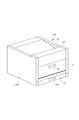
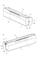
図1は本実施例におけるカラー電子写真画像形成装置(以下、画像形成装置と称する)100の外観斜視図、図2(a)は画像形成装置100の縦断右側面図、図2(b)は図2(a)の部分的な拡大図である。画像形成装置100は、電子写真プロセスを用いた、4色フルカラーのレーザープリンタである。即ち、画像形成装置100は、パソコン・イメージリーダ・相手方ファクシミリ装置等のホスト装置(不図示)から制御回路部199へ入力する電気的画像信号に基づいて、記録媒体Sにフルカラーの画像形成を行う。
Example 1
(Overall configuration of color electrophotographic image forming apparatus)
FIG. 1 is an external perspective view of a color electrophotographic image forming apparatus (hereinafter referred to as an image forming apparatus) 100 in this embodiment, FIG. 2A is a vertical right side view of the
以下の説明において、画像形成装置100に関して、前側又は正面側とは装置開閉用のドア10を配設した側である。後側とはそれとは反対側である。前後方向とは、画像形成装置の後側から前側に向かう方向(前方向)と、その逆の方向(後方向)である。左右とは画像形成装置を前側から見て左又は右である。左右方向とは、右から左に向かう方向(左方向)と、その逆の方向(右方向)である。また、装置本体100Aとは、カートリッジを除いた画像形成装置部分である。
In the following description, with respect to the
本実施例の画像形成装置100は、イエロー(y)、マゼンタ(m)、シアン(c)、ブラック(k)の各色の現像剤像(トナー像)を形成する4つのプロセスカートリッジP(Py・Pm・Pc・Pk)を横方向に配列した、所謂横タンデム型である。画像形成装置100は、複数のカートリッジPを装置本体100Aに着脱可能で、記録媒体Sにカラー画像を形成する。
The
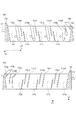
即ち、装置本体100Aの内部には、後側から前側にかけて順にほぼ水平方向に4個のプロセスカートリッジP(Py・Pm・Pc・Pk)が並設されている。各プロセスカートリッジ(以下、カートリッジと記す)Pは、それぞれ、静電潜像が形成される電子写真感光体ドラム1(以下、ドラムと記す)を備えている。ドラム1は、図2(b)に示すように反時計回り方向(矢印方向)に回転駆動される。このドラム1の周囲には、ドラム回転方向に従って順に、ドラムに作用するプロセス手段としての、帯電手段2、現像手段4(4y・4m・4c・4k)、ドラムクリーニング手段6が配置されている。
That is, four process cartridges P (Py, Pm, Pc, Pk) are arranged in parallel in the horizontal direction from the rear side to the front side in the apparatus
尚、本実施例では、カートリッジの一例として前述した所謂一体型のプロセスカートリッジを例に挙げて説明するが、本発明はこれに限定されるものではない。 In the present embodiment, the above-described so-called integrated process cartridge will be described as an example of the cartridge, but the present invention is not limited to this.
ドラム1は、例えばアルミシリンダの外周面に有機光導電体層(OPC感光体)を塗布したものである。 The drum 1 is obtained by, for example, applying an organic photoconductor layer (OPC photoconductor) to the outer peripheral surface of an aluminum cylinder.
帯電手段(プロセス手段)2は帯電部材として帯電ローラ(ローラ状に形成された導電性ローラ)を用いた接触帯電方式を用いている。帯電ローラ2はドラム1に対してほぼ並行にかつ当接して配設されており、ドラム1の回転に従動して回転する。そして、この帯電ローラ2に電源部(不図示)から所定の帯電バイアス電圧が印加されることで、ドラム1の表面が所定の極性・電位を一様に帯電される。
The charging means (process means) 2 uses a contact charging method using a charging roller (conductive roller formed in a roller shape) as a charging member. The charging
現像手段(プロセス手段)4は、ドラム1に形成された静電潜像を現像剤(トナー)を用いて現像する現像ユニットである。各カートリッジPの有する現像ユニット4(4y・4m・4c・4k)は、現像剤T(Ty・Tm・Tc・Tk)を収容した現像剤収容部41(41y・41m・41c・41k)と、ドラム1に対する現像部材としての現像ローラ40と、を有する。また、現像剤収容部41に収容された現像剤Tを搬送する現像剤搬送部材42、現像ローラ40に対する現像剤塗布部材としての現像剤供給ローラ43、現像ローラ40の外周に圧接された現像剤規制部材としての現像ブレード44を有する。
The developing means (process means) 4 is a developing unit that develops the electrostatic latent image formed on the drum 1 using a developer (toner). The developing unit 4 (4y, 4m, 4c, 4k) of each cartridge P includes a developer container 41 (41y, 41m, 41c, 41k) that houses a developer T (Ty, Tm, Tc, Tk), And a developing
ドラムクリーニング手段(プロセス手段)6は、ドラム1の周面に形成された現像剤像を転写ベルト50に一次転写した後、ドラム1の表面から転写残現像剤を除去する手段である。本実施例ではクリーニング部材としてクリーニングブレードを用いている。ドラム表面から除去された現像剤は除去現像剤収容部81に収容される。
The drum cleaning means (process means) 6 is a means for removing the transfer residual developer from the surface of the drum 1 after first transferring the developer image formed on the peripheral surface of the drum 1 to the
各カートリッジPは、上記のドラム1・帯電ローラ2・ドラムクリーニング手段6を有する感光体ユニット8と、現像ユニット4(4y・4m・4c・4k)とが結合されて構成されている。そして、各カートリッジPは、装置本体100Aに対して引き出し方式にて着脱交換可能である。カートリッジPの更なる詳細な構成及び引き出し方式については後述する。
Each cartridge P is configured by combining the
カートリッジPy(第二のカートリッジ)は、現像ユニット4yの有する現像剤収容部41yにイエロー色(y色)の現像剤Tyを収容したものであり、ドラム1の面にイエロー色の現像剤像を形成する。カートリッジPm(第一のカートリッジ)は、現像ユニット4mの有する現像剤収容部41mにマゼンタ色(m色)の現像剤Tmを収容したものであり、ドラム1の面にマゼンタ色の現像剤像を形成する。カートリッジPc(第一のカートリッジ)は、現像ユニット4cの有する現像剤収容部41cにシアン色(c色)の現像剤Tcを収容したものであり、ドラム1の面にシアン色の現像剤像を形成する。カートリッジPk(第一のカートリッジ)は、現像ユニット4kの有する現像剤収容部41kにブラック色(k色)の現像剤Tkを収容したものであり、ドラム1の面にブラック色の現像剤像を形成する。
Cartridges Py (second cartridge) is obtained by accommodating the developer Ty of yellow (y color) in the
装置本体100Aの内部に装着されたカートリッジP(Py・Pm・Pc・Pk)の下側には、画像露光手段としてのレーザースキャナユニット3が配置されている。また、上側には、転写ユニット5が配置されている。
A
スキャナユニット3は、レーザーダイオード、ポリゴンミラー、Fθレンズ、反射ミラー等を有し、ホスト装置から制御回路部199へ入力する各色の画像情報に対応して変調したレーザービームLを出力してドラム1の帯電処理面を走査露光する。これによって、ドラム1面に走査露光パターンに対応した静電潜像が形成される。
The
転写ユニット5は、誘電体性で可撓性を有するエンドレスの中間転写ベルト(無端状ベルト)50を有する。また、転写ベルト50を懸回張設する第1と第2のベルト懸架ローラ51a・51bを有する。また、転写ベルト50の内側で、ベルト懸架ローラ51a・51bの間に配置されていて、転写ベルト50を挟んで各カートリッジPのドラム1に圧接している4本の一次転写ローラ52(52y、52m、52c、52k)を有する。各カートリッジ50のドラム1とベルト50の接触部がそれぞれ一次転写ニップ部T1である。また、ベルト懸架ローラ51bにはベルト50を介して二次転写ローラ53が接触している。ベルト懸架ローラ51aとベルト50との接触部が二次転写ニップ部T2である。
The
フルカラー画像を形成するための動作は次の通りである。各カートリッジPが所定の制御タイミングにて順次に駆動される。即ち、各ドラム1が反時計方向(図2の矢印方向)に回転駆動する。ベルトユニット5の転写ベルト50も回転駆動される。スキャナユニット3も駆動される。この駆動に同期して各カートリッジPにおいて帯電ローラ2がドラム1の表面を所定の極性・電位に一様に帯電する。スキャナユニット3は各ドラム1の表面に対応の画像信号に応じたレーザービーム走査露光を行なう。これによって各ドラム1の表面に対応の画像信号に応じた静電潜像が形成される。形成された静電潜像を現像ユニット4(4y・4m・4c・4k)(現像ローラ40)によって現像する。即ち、現像剤像を形成する。
The operation for forming a full-color image is as follows. Each cartridge P is sequentially driven at a predetermined control timing. That is, each drum 1 is rotationally driven in the counterclockwise direction (the arrow direction in FIG. 2). The
上記のような電子写真プロセス動作により、カートリッジPyのドラム1には、フルカラー画像のイエロー成分像に対応するy色の現像剤像が形成される。カートリッジPmのドラム1には、フルカラー画像のm成分像に対応するマゼンタ色の現像剤像が形成される。カートリッジPcのドラム1には、フルカラー画像のシアン成分像に対応するc色の現像剤像が形成される。カートリッジPkのドラム1には、フルカラー画像のブラック成分像に対応するk色の現像剤像が形成される。それらの各現像剤像が、各一次転写ニップ部T1において、循環移動するベルト50上に順次に所定に重畳されて静電的に一次転写される。かくして、転写ベルト50上にy色+m色+c色+k色の4色重畳の未定着フルカラー現像剤像が形成される。
By the electrophotographic process operation as described above, a y-color developer image corresponding to the yellow component image of the full-color image is formed on the drum 1 of the cartridge Py. A magenta developer image corresponding to the m component image of the full-color image is formed on the drum 1 of the cartridge Pm. A c-color developer image corresponding to the cyan component image of the full-color image is formed on the drum 1 of the cartridge Pc. A k-color developer image corresponding to the black component image of the full-color image is formed on the drum 1 of the cartridge Pk. Each of these developer images is electrostatically primary-transferred in a predetermined manner sequentially superimposed on the
一方、所定の制御タイミングで給送部16の給送ローラ18が回転して、記録媒体Sが収容されている給送カセット17から記録媒体Sが1枚分離されて給送される。カセット17は装置本体100Aの前側から出し入れ自由である(フロントローデング)。17aは給送カセット17の前面に設けられた指掛け部である。給送された記録媒体Sは、レジストローラ対19によって所定の制御タイミングにて、二次転写ニップ部T2に導入される。転写ローラ53には電源部(不図示)から現像剤の帯電極性(トナーの帯電極性)とは逆極性で且つ所定電位の転写バイアスが印加される。これにより、記録媒体S上にy色+m色+c色+k色の4色の現像剤像が重畳して二次転写される。すなわち、記録媒体S上に未定着のフルカラー現像剤像が形成される。
On the other hand, the feeding
次に、記録媒体Sは二次転写ニップ部T2から分離されて定着部20へ導入される。定着部20は、記録媒体Sに転写された複数色の現像剤像を定着させるものである。定着部20は、回転する加熱ローラ20aと、これに圧接して記録媒体Sに熱及び圧力を与える加圧ローラ20bを有する。現像剤像が形成された記録媒体Sは、定着部20を通過する際に、定着ローラ対20a・20bで挟持搬送される。そして、定着ローラ対20a・20bによって熱及び圧力を与えられる。これによって複数色の現像剤像が記録媒体Sの表面に定着される。そして、記録媒体Sは定着部20を出て、フルカラー画像形成物として排出ローラ対23を含む搬送路を通って排出部24から装置本体外の排出トレイ25に排出される。記録材分離後のベルト50の表面に残留したトナーは、本例においては、例えばカートリッジ50yの一次転写ニップ部T1においてドラム1の表面に静電的に付着し、装置6にて除去される。
尚、モノクロ画像形成モードの場合は、カートリッジPkを用いた画像形成だけが行われる。
Next, the recording medium S is separated from the secondary transfer nip T <b> 2 and introduced into the fixing
In the monochrome image formation mode, only image formation using the cartridge Pk is performed.
(カートリッジ交換方式)
各カートリッジPは、現像剤が消費され寿命となった際には、使用者が交換することができるようになっている。本実施例の画像形成装置において、カートリッジの交換は、カートリッジを引き出し式の枠型部材であるカートリッジ支持部材としての引き出し部材70に乗せて、フロントアクセスにより交換することができる。カートリッジPを装置本体100Aに対して着脱するに当たって、装置本体100Aの外側に引き出した状態の引き出し部材70に対してカートリッジPを着脱する。そして、カートリッジPを支持した引き出し部材70を、装置本体100A内に押し込む。これによって、カートリッジPを装置本体100A内の所定の位置に装着することができる。
(Cartridge replacement method)
Each cartridge P can be replaced by the user when the developer is consumed and its life is reached. In the image forming apparatus of the present embodiment, the cartridge can be replaced by front access by placing the cartridge on a
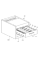
装置本体100Aの前側には前面開口部100aが設けられている。この開口部100aは、装置本体100Aの内側へカートリッジを押し込む、又は、装置本体100Aからカートリッジを引き出す際に、カートリッジを支持させた引き出し部材(カートリッジ支持部材)70が通過する開口部である。装置本体100Aの前側には、回動可能なドア10が配設されている。ドア10は、開口部100aを閉じる閉鎖位置と開口部100aを開放する開放位置とを取り得る開閉部材である。本実施例においては、ドア(開閉部材)10は、ドアの下側に位置するヒンジ部10bを中心に装置本体100Aに対して開閉回動可能である。即ち、ドア10は、ヒンジ部10bを中心に立て起こすように回動して開口部100aを図1・図2(a)に示すように閉じ状態にすることができる。また、ヒンジ部10bを中心に装置本体100Aの前側に倒すように回動して開口部100aを図3・図4に示すように開き状態にすることができる。10aはドア10の前面に設けられた指掛け部である。
A
引き出し部材70は、ドア10が開かれた図3・図4に示す状態において、開口部100aを通過して前後方向に、ガイド手段14にガイドされて移動する。即ち、引き出し部材70は、装置本体100Aに対して、実質的に水平方向である矢印D1方向(押し込み方向:後方向)とその逆のD2方向(引き出し方向:前方向)とに移動可能に設けられている。そして、各カートリッジPは、その長手方向(ドラム1の軸線方向、現像ローラ40の軸線方向)が引き出し部材70の移動方向(矢印D1,D2と同方向)に隣接した状態で配列されて、引き出し部材70に支持されている。即ち、引き出し部材70は、複数のカートリッジP(Py・Pm・Pc・Pk)を一方向に隣接して配列した状態で支持している。そして、引き出し部材70は、ドア10が開かれている状態において、カートリッジPを装置本体100Aの内側に位置させるための内側位置Aと、内側位置Aから引き出されて各カートリッジを着脱できる引き出し位置(外側位置)Bと、の間を移動可能である。内側位置Aは例えば図2に示す状態である。引き出し位置Bは、例えば図3・図4に示す状態である。
In the state shown in FIGS. 3 and 4 in which the
ドア10が閉じられている状態(図1・図2)において、引き出し部材70は内側位置Aに位置している。内側位置Aは、引き出し部材70が各カートリッジPを支持し、装置本体100Aの内側において、ドラム1に静電潜像を形成できる潜像形成位置(画像形成位置)である。即ち、各カートリッジPが装置本体100Aに対する装着位置に位置している。そして、各カートリッジPの各ドラム1が転写ベルト50に接触しており、ドラム1から、転写ベルト50へ現像剤像の一次転写が可能な状態である。内側位置Aにおいて、各カートリッジPは、押圧部材に押されて所定の位置決め部(不図示)に固定された状態にされている。この状態で、各カートリッジの有する駆動入力部(カップリング部材47、48:図8)に対して装置本体100Aに設けられた駆動出力部(不図示)が結合している。各カートリッジの電気接点(不図示)に対して装置本体側の給電系統(不図示)が導通している。引き出し部材70は、装置本体100Aに対して位置決め固定手段(不図示)により位置決め固定されている。この状態において、画像形成装置100は画像形成動作が可能である。
In the state where the
ドア10が図3・図4に示すように開かれると、装置本体100Aの開口部100aが開放される。そして、開口部100aに引き出し部材70の前枠の前面に配設された把手部71が露呈する。また、ドア10の開き回動動作に連動する連動機構(不図示)により、ベルトユニット5が所定の位置まで上昇する。これにより、各カートリッジPのドラム1から転写ベルト11が離隔する。即ち、ドラム1に対するベルト11の接触が解除される。また、各カートリッジPの駆動入力部に対する装置本体側の駆動出力部の結合が解除される(駆動解除)。また、各カートリッジPを位置決め固定している押圧部材の押圧が解除される(押圧解除)。また、各カートリッジPの電気接点に対する装置本体側の給電系統の導通が解除される(給電解除)。また、引き出し部材70の装置本体100Aに対する位置決め固定手段による位置決め固定が解除される。
When the
そこで、使用者は、把手部71をつかんで引き出し部材70を引き出し方向D2である前方向に水平にスライド移動させる。そして、引き出し部材70を開口部100aから装置本体100Aの外側の所定の引出し位置Bまで十分に引き出す。引き出し部材70は所定の引出し位置Bまで十分に引き出されると、ストッパ部材(不図示)によりそれ以上の引き出し移動が阻止される。この引き出し部材70の引出し移動時には、各カートリッジPのドラム1と転写ベルト50とが離隔している。したがって、両者間での擦れは生じない。
Therefore, the user grasps the
引き出し部材70は個々のカートリッジP(Py・Pm・Pc・Pk)をそれぞれ上方に取り出し可能であり、及び、それぞれ下方に向かって移動させることによって支持する構成である。そこで、使用者が、交換すべき使用済みのカートリッジを引き出し部材70から持ち上げて外す(図4の上向き矢印C1)。そして、新しいカートリッジを、引き出し部材70に対して、その上方から実質的に重力方向である下向きに落とし込む(下向き矢印C2)。これによって、カートリッジPは引き出し部材70に支持される。
The
引き出し部材70に対するカートリッジの交換作業を終えたら、使用者は引き出し部材70を装置本体100Aに対して引き出し方向D2とは逆の押し込み方向D1である後方向に水平にスライド移動させる。そして、引き出し位置Bから内側へ十分に押し込み移動させる。引き出し部材70は内側へ十分に押し込まれると、ストッパ部材(不図示)によりそれ以上の押し込み移動が阻止される。この引き出し部材70の押し込み移動時には、各カートリッジPのドラム1と転写ベルト50とは離隔しているので両者間での擦れは生じない。
When the replacement operation of the cartridge with respect to the
引き出し部材70を内側へ十分に押し込んだら、ドア10を閉じる。ドア10の閉じ動作により、装置本体100Aの開口部100aが閉鎖される。また、ドア10の閉じ動作に連動する連動機構により、引き出し部材70が装置本体100Aに対して位置決め固定手段にて位置決め固定される。また、各カートリッジPは、押圧部材(不図示)に押されて所定の位置決め部に固定された状態になる。また、各カートリッジPの駆動入力部に対して装置本体側の駆動出力部が結合する。また、各カートリッジPの電気接点に対して装置本体側の給電系統が導通する。そして、転写ユニット5が所定の位置まで下降する。これにより、各カートリッジPのドラム1の上面に対して転写ベルト50が接触した状態になる。本実施例によれば、この状態において、画像形成装置100は画像形成動作が可能な状態となる。
When the
上記のように、複数のカートリッジPは引き出し部材70に支持された状態で、引き出し部材70と共に装置本体100内へ進入する。従って、使用者は、引き出し部材70を装置本体100A内の内側に進入させ、ドア10を閉じる。これにより、複数のカートリッジPを装置本体100Aに対して確実に装着できる。このため、各カートリッジPを個別に使用者が装置本体100A内へ装着する構成と比較して、着脱操作性が向上する。
As described above, the plurality of cartridges P enter the apparatus
(引き出し部材)
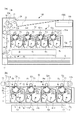
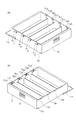
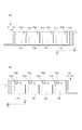
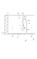
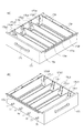
引き出し部材(カートリッジ支持部材)70について図5乃至図7を用いて説明する。図5(a)は引き出し部材70を左斜め上方より見た斜視図、図5(b)は右斜め上方より見た斜視図である。図6(a)は引き出し部材70の縦断左側面図、(b)は同じく縦断右断面図である。図7は図6(a)の一部を拡大してカートリッジ装着部70a付近を示した図である。
(Drawer member)
The drawer member (cartridge support member) 70 will be described with reference to FIGS. FIG. 5A is a perspective view of the
引き出し部材70の外壁の四隅部には、装置本体100Aの左右のガイド手段14に係合してガイドされる被ガイド部72a〜72dが設けられている。被ガイド部72aと72cは装置本体100Aの右側に設けられたガイド手段14に係合してガイドされる。また、被ガイド部72bと72dは装置本体100Aの左側のガイド手段14に係合してガイドされる。
At the four corners of the outer wall of the
引き出し方向D2において上流側に設けられた被ガイド部72aと72bは、引き出し部材70が引き出し位置Bにおいて装置本体100Aに対して傾かないようにしている。即ち、図5に示すとおり、引き出し方向D2に対して最上流側に位置する装着部(支持部)70aからさらに上流側に突出して設けられている。また、引き出し方向D2における下流側には、被ガイド部72cと72dが円柱形状の突出部として設けられている。
また、引き出し部材70の前枠の前面部には、引き出し部材70を使用者が操作する為の把手部71が設けられている。
Guided
Further, a
引き出し部材70には、後述するカートリッジPを装着するための4つの装着部70a〜70dが前後方向に一列に設けられている。引き出し方向D2の上流側から順に、カートリッジPyを装着するための装着部70a、カートリッジPmを装着するための装着部70b、カートリッジPcを装着するための装着部70c、カートリッジPkを装着するための装着部70dが設けられる。装着部70aは第二の装着部であり、装着部70b、70c、70dは第一の装着部である。各装着部70a〜dの間には仕切り板70eが設けられていて、カートリッジPを装着する際の目安(目印)になっている。各装着部70a〜70dの下部には、開口部70fがそれぞれ設けられている。レーザースキャナユニット3のレーザーLが開口部70fを通過してドラム1を走査露光する。
The
各装着部70a〜70dの左右両側面には、カートリッジPを引き出し部材70内に装着するためのガイド手段75が設けられている。装着部70aの右側(非駆動側)側端部には、カートリッジPkを引き出し部材70内に装着するためのガイド部75a1とガイド部75a3が設けられている。また、カートリッジ装着部70aの左側(駆動側)側端部には、ガイド部75a2と75a4が設けられている。同様に、カートリッジ装着部70bの左右側端部にはガイド部75b1〜75b4が、カートリッジ装着部70cの左右側端部にはガイド部75c1〜75c4が、カートリッジ装着部70dの左右側端部にはガイド部75d〜75c4が、それぞれ設けられる。
Guide means 75 for mounting the cartridge P in the
本実施例において、ガイド部75b・75c・75dは共通の形状としている。ガイド部75bを例に説明する。図6(a)に示すように、装着部70bの右側端部では、引き出し方向D2の上流側にガイド部75b1、下流側にガイド部75b3が、どちらも同じ幅で、略鉛直方向に一直線状のガイド部として設けられている。また、図6(b)に示すように、装着部70bの左側端部では、引き出し方向の上流側にガイド部75b2、下流側に75b4が、右側端部のガイド部75b1・75b3と対向して、略鉛直方向に延在して設けられている。ガイド部75b2と係合するカートリッジの被ガイド部63qは、後述するように、カップリング部材47を囲む円筒状のリブとして形成されるため、ガイド部75b2は他のガイド部と異なる幅としている。ガイド部75bにおいては、ガイド部75b1・75b2と比較してより下方へ延在するガイド部75b3・75b4が、主としてカートリッジをガイド(案内)する機能を果たす。
In the present embodiment, the guide portions 75b, 75c, and 75d have a common shape. The guide portion 75b will be described as an example. As shown in FIG. 6A, at the right end portion of the mounting
一方、引き出し方向D2における最も上流側の装着部70aのガイド部75aは、下流側の3つのガイド部75b・75c・75dと異なる構成としている。ガイド部75a1・75a2は、前述したガイド部75b1・75b2と共通の形状である。第二のガイドであるガイド部75a3・75a4は、上下2つの部位により構成される。下部はガイド部75b3・75b4と同様に略鉛直方向であるが、傾斜部である上部は前側(引き出し方向D2)に向かうよう傾斜させている。図7に示すように、引き出し部材の引き出し方向D2と、カートリッジPm・Pc・Pkの取り出し方向でありガイド部75a3下部と略平行であるC1と、がなす角度θ1とする。そして角度θ1は、引き出し方向D2と、ガイド部75a3上部のカートリッジ取り外し方向C2と、がなす角度θ2が小さくなるよう構成する。
On the other hand, the guide portion 75a of the most upstream mounting
また、引き出し部材70の駆動側(左側)には、画像形成装置本体に設けられたドラムカップリング部材(不図示)が進入するための開口部77、および現像カップリング部材(不図示)が進入する為の開口部78が設けられている。各カップリング部材は、ドア10を閉める動作に連動して開口部77及び開口部78に進入する。その後、後述するカートリッジPのカップリング部材と係合してカートリッジPに駆動力を伝達する。
Further, an
(カートリッジ)
引き出し部材70に装着される(支持される)カートリッジについて図2(b)、図8(a)(b)、図9(a)(b)を用いて説明する。図2(b)は画像形成装置100の縦断右断面図のうち、引き出し部材70およびカートリッジPの付近を拡大した図である。ここでは代表としてカートリッジPkを例にとって説明する。他の色のカートリッジPy・Pm・Pcに関しては、収容している現像剤の色が異なる以外の構成は一緒である。ただし、カートリッジPyに関しては、把持部の形状を他のカートリッジPm・Pc・Pkと異なる形状(把持部66)としている(後述)。
(cartridge)
The cartridge mounted (supported) on the
カートリッジPkは、感光体ユニット8と現像ユニット4kとが一体化されて構成される。ユニット8は、ドラム1と、帯電ローラ2と、クリーニング手段6及び、クリーニング手段6により除去された現像剤を収容する除去現像剤収容部81を有する。また、現像ユニット4kは、現像ローラ40と、現像剤供給ローラ43と、現像ブレード44、及び、画像形成に使用される現像剤Tkを収容する現像剤収容部41kと、を有する。
The cartridge Pk is configured by integrating the
ドラム1、現像ローラ40、現像剤供給ローラ43は矢印の方向に回転駆動される。帯電ローラ2はドラム1の回転に従動して回転する。帯電ローラ2には、所定の帯電バイアスが印加される。現像ローラ40には、所定の現像バイアスが印加される。
The drum 1, the developing
現像剤収容部41k内の現像剤Tkは、回転中心軸にシート状の部材を取り付けた現像剤搬送部材42によって上方へ搬送され、現像剤供給ローラ43へ送り込まれる。そして、供給ローラ43と、現像ローラ40の外周に圧接された現像ブレード44とによって、現像剤Tkが現像ローラ40の外周に塗布される。かつ現像剤Tkには、ブレード44によって所定の極性の電荷が付与される。そして、装置本体100A側から所定の現像バイアスが現像ローラ40に印加される。これにより、ドラム1に形成された静電潜像が現像剤像として現像される。ドラム1上に形成された現像剤像が、記録媒体Sに転写された後、ドラム表面に残った現像剤はクリーニング手段6によって除去され、除去現像剤収容部81内に収容される。
The developer Tk in the developer accommodating portion 41k is conveyed upward by a developer conveying member 42 having a sheet-like member attached to the rotation center axis, and is sent to the
図8(a)(b)はカートリッジPkを右斜め上方および左斜め上方よりそれぞれ見た斜視図である。カートリッジPkの駆動側端部には、装置本体側のドラムカップリング部材(不図示)より駆動力を受ける為のカップリング部材47が回転可能に設けられている。また現像カップリング部材(不図示)から駆動力を受ける為のカップリング部材48が回転可能に設けられている。
FIGS. 8A and 8B are perspective views of the cartridge Pk as viewed from the upper right and the upper left. A
カップリング部材47は、ドラム1の駆動側(左側)端部に設けられている。そして、装置本体100Aからカップリング部材47が受けた駆動力はドラム1を回転させる。また、カップリング部材48が受けた駆動力は現像ローラ40に、また、中間ギア(不図示)を介して現像剤搬送部材42や現像剤供給ローラ43に伝達される。
The
カートリッジPの左右両側面には、カートリッジPを引き出し部材70に装着する際にガイド部75と係合してガイドされるための被ガイド部63が設けられている。カートリッジPkの右側面には、図8(a)に示すように、被ガイド部63pおよびその下方に被ガイド部63rが、それぞれ外側に突出した円柱形状の突起として設けられている。カートリッジPkの左側面には、図8(b)に示すように、カップリング部材47を囲んでいる円筒状のリブとして形成された被ガイド部63q、およびその下方に、突出した円柱形状である被ガイド部63sが設けられている。
On both left and right side surfaces of the cartridge P, there are provided guided
感光体ユニット8には穴部82R・82Lが設けられている。現像ユニット4kには突出部49R・49Lが設けられている。穴部82Rが突出部49Rと、穴部82Lが突出部49Lと、それぞれ係合することで、感光体ユニット8と現像ユニット4とが結合されている。
The
図9(a)(b)はカートリッジPyを右斜め上方および左斜め上方よりそれぞれ見た斜視図である。カートリッジPyは、把持部66のみ、カートリッジPm・Pc・Pkの把持部65と異なる形状としている。それ以外は前述したカートリッジPkと同じ構成である。図8(a)(b)に示すように、カートリッジPm・Pc・Pkの把持部65は略鉛直方向に設けられている。一方、カートリッジPyの把持部66は、その根元(下部)から先端(上部)へ向かって、前側に傾斜した形状である。
FIGS. 9A and 9B are perspective views of the cartridge Py as viewed obliquely from the upper right and from the upper left. The cartridge Py has a shape different from the gripping
(引き出し部材へのカートリッジの装着(支持))
引き出し部材70への各カートリッジP(Py・Pm・Pc・Pk)の装着(支持)について、図6乃至図10を用いて説明する。図10は、カートリッジPyおよびカートリッジPcを引き出し部材70から取り出す途中の状態での画像形成装置100の縦断右側面図である。
(Mounting the cartridge to the drawer member (support))
Mounting (supporting) of each cartridge P (Py, Pm, Pc, Pk) to the
各カートリッジPy・Pm・Pc・Pkは、引き出し部材70に設けられた対応の装着部70a・70b・70c・70dに各々装着される。使用者は、引き出し部材70における対応の装着部に対してカートリッジPを実質的に重力方向である矢印C2方向に下して装着を行う。ここでは代表してカートリッジPcを例にとって説明する。カートリッジPm・Pc・Pkに関しては、カートリッジPを装着する装着部がそれぞれ装着部70b・70c・70dと異なる以外の装着操作は同様である。カートリッジPyの装着については後述する。
The cartridges Py, Pm, Pc, and Pk are mounted on corresponding mounting
ユーザがカートリッジPcを引き出し部材70の装着部70cに装着するには、把持部65をつかみ、カートリッジPcの左右両端部に設けられた被ガイド部63rと被ガイド部63sを、装着部70dのガイド部75c3と75c4にそれぞれ係合させる。被ガイド部63r・63sと係合したガイド部75c3・75c4にガイドされながら、カートリッジPcはC2方向(下方)へ下りていく。次に、カートリッジPcの被ガイド部63pと63qを、ガイド部75c1と75c2にそれぞれ係合させる。カートリッジPcをさらにC2方向に下ろしていけば、被ガイド部63がガイド部75の下端部に突き当たり、引き出し部材70へのカートリッジPcの装着が完了する。
In order for the user to mount the cartridge Pc on the mounting
次に、引き出し部材70に対するカートリッジPyの装着について説明する。ユーザはカートリッジPyの把持部66をつかみ、カートリッジPyの左右両端部に設けられた被ガイド部63r・63sを、装着部70aの両端のガイド部75a3・75a4に係合させる。次に、重力に従いながらC2方向に下ろしていくが、前述の通りガイド部75a3・75a4はC3方向(前側)に傾斜した形状としているため、カートリッジPyは斜めに移動する、すなわち後側に移動しながら下方へ下りていく、動作となる。最後に、被ガイド部63p・63qを、ガイド部75a1・75a2と係合させ、さらに下方へ下ろしていけば、被ガイド部63がガイド部75の下端部に突き当たり、引き出し部材70へのカートリッジPyの装着が完了する。
Next, attachment of the cartridge Py to the
引き出し部材70に装着されたカートリッジPを取り出すときには、上記と逆の操作を行う。カートリッジPcを取り出すには、ユーザが把持部65をつかみ、鉛直上方であるC2方向に引き上げる。それによって、被ガイド部63p・63qとガイド部75c1・75c2との係合がはずれ、続いて、被ガイド部63r・63sとガイド部75c3・75c4との係合がはずれて、カートリッジPcを装着部70cより取り出すことができる。カートリッジPm・Pkの取り出し操作も同様である。
When the cartridge P mounted on the
カートリッジPyを引き出し部材70から取り出すためには、ユーザが把持部66をつかみ、まずはカートリッジPcの取り出し操作と同様に、カートリッジPyを鉛直上方であるC2方向へ引き上げる。すると、被ガイド部63p・63qとガイド部75a1・75a2との係合がはずれる。カートリッジPyをさらに引き上げていくと、ガイド部75a3・75a4がC3方向に傾斜して設けられているため、ガイド部75a3・75a4と係合している被ガイド部63r・63s、および被ガイド部を有するカートリッジPyがC3方向に斜めに移動する。すなわちカートリッジPyは前方向へ移動しながら上方へ引き上げられていく。最後に被ガイド部63r・63sとガイド部75a3・75a4との係合がはずると、カートリッジPyを装着部70aより取り出すことができる。ガイド部75a3・75a4は、カートリッジPyを装着部70aより取り外す際に、カートリッジPyの引き出し方向D2への移動量がそれ以外のカートリッジPk、Pc、Pmの引き出し方向への移動量より大きくなるよう構成されることになる。
In order to take out the cartridge Py from the
ユーザは上記のカートリッジPの着脱操作を、画像形成装置の前側に正対して前側から実行する(フロントアクセス)。引き出し部材70を所定位置まで前側に引き出してカートリッジPyを装着または取り出すとき、カートリッジPyの装着部70aはユーザから最も離れた位置にある。そこで、ガイド部75aによれば、装着部70aのガイド部をガイド部75b〜75dと同様とした場合と比べて、ユーザは、引き出し部材のガイド部75aとカートリッジPyの被ガイド部63との係合および係合解除を、より前側でおこなうことができる。つまり、カートリッジPyを装着するときは、よりユーザに近い位置からカートリッジPyがガイドされて装着位置へ導かれる。また、カートリッジPyを取り出すときは、よりユーザに近い位置までカートリッジPyがガイドされる。これよって、引き出し部材70の引き出し方向D2における最も上流側に支持されたカートリッジPyを着脱する際の操作性が向上する。
The user executes the above-described attachment / detachment operation of the cartridge P from the front side facing the front side of the image forming apparatus (front access). When the
本実施例のガイド部75aによってカートリッジPyを前側へ移動させると、すなわち、カートリッジPyと装置本体100Aとの距離が大きくなる。カートリッジPyが装置本体100Aから離れる方向にガイドされることで、カートリッジPyの着脱時に、カートリッジPyが装置本体100Aと接触しにくくなる。よって、カートリッジPyの有するプロセス部材であるドラム1や、あるいはカートリッジPyの表面や装置本体100Aの表面を損傷しにくくすることができる。
When the cartridge Py is moved forward by the guide portion 75a of the present embodiment, that is, the distance between the cartridge Py and the apparatus
本実施例のカートリッジPについては、ドラム1を含む感光体ユニット8が前側、現像ユニット4が後側の姿勢で引き出し部材70に装着される。ドラム1を有する感光体ユニットを装置本体から離れた前側とすることで、ドラム1をより損傷しにくくすることができる。
With respect to the cartridge P of this embodiment, the
また、ユーザがカートリッジPを把持する際にドラム1に触れるおそれがあるため、ドラム1より前側に第一の把持部である把持部65を設けている。これにより、カートリッジPの着脱時にユーザがドラム1に触りにくく、ドラム1が損傷しにくくすることができる。
Further, since the user may touch the drum 1 when gripping the cartridge P , a
カートリッジPyの把持部66は、前述のように、Pm・Pc・Pkの把持部65と異なる形状であって、下部から上部へ向かって前側に傾斜している。第二の把持部である把持部66の形状を第一の把持部である把持部65の形状に対して変えることで、着脱経路が異なることをユーザに報知でき、また、操作を行うユーザの方向へ把持部を傾けることで、着脱時のカートリッジPyの操作性を向上させることができる。
As described above, the
なお、本実施例において、ガイド部75a3・75a4は、下部をガイド部75b〜75dの相当部と同様の形状とし、上部を前側へ傾斜させガイド部75b〜75dと異ならせた形状としている。しかし、全体が一直線状で手前に傾斜したガイド部、あるいは、下部が手前に傾斜していて上部は鉛直方向としたガイド部、とした変形例も考えられる。ただし、このような構成とすると、カートリッジPyとPmとが接触干渉することを防ぐために、カートリッジ間の距離をあけたり、カートリッジに凹部を設けたりする必要がある。そのため、画像形成装置の大型化やカートリッジの容量低下につながるおそれがあるため望ましくない。 In the present embodiment, the guide portions 75a3 and 75a4 have the same shape as the corresponding portions of the guide portions 75b to 75d, and the upper portions are inclined to the front side and different from the guide portions 75b to 75d. However, a modified example in which the entire guide is straight and inclined forward, or the lower part is inclined forward and the upper part is vertically oriented is also conceivable. However, with such a configuration, in order to prevent contact interference between the cartridges Py and Pm, it is necessary to increase the distance between the cartridges or to provide a recess in the cartridge. This is undesirable because it may lead to an increase in the size of the image forming apparatus and a reduction in the capacity of the cartridge.
また、本実施例において、ガイド部75a3・75a4は2つの直線形状の部位の組み合わせにより構成されるが、一直線状、あるいは3つ以上の直線部の組み合わせによって構成されていてもよい。また、円弧などの曲線部を有していてもよい。 Further, in the present embodiment, the guide portions 75a3 and 75a4 are configured by a combination of two linear portions, but may be configured by a linear configuration or a combination of three or more linear portions. Moreover, you may have curved parts, such as a circular arc.
また、ガイド部75b〜75dは略鉛直方向に直線状に形成されているが、これに限定されるものでなく、傾斜していてもよい。前側のガイド部75b〜75dが傾斜している場合においても、θ1に対してθ2の角度を小さく設定したガイド部75aとすることで、本実施例同様の効果を得ることができる。 Moreover, although the guide parts 75b-75d are linearly formed in the substantially perpendicular direction, it is not limited to this, You may incline. Even when the front guide portions 75b to 75d are inclined, the same effect as in the present embodiment can be obtained by setting the guide portion 75a to have an angle θ2 smaller than θ1.
(実施例2)
次に、第2の実施例について説明する。尚、本実施例では、前述した実施例1と異なる構成、動作について説明し、同様の構成、機能を有する部材については同一の参照番号を付して先の実施例1の説明を援用する。
(Example 2)
Next, a second embodiment will be described. In the present embodiment, configurations and operations different from those of the first embodiment will be described, and members having similar configurations and functions are denoted by the same reference numerals, and the description of the first embodiment is used.
(カラー電子写真画像形成装置の全体構成)
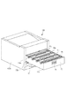
図11は本実施例におけるカラー電子写真画像形成装置(以下、画像形成装置と称する)200の外観斜視図、図12(a)は画像形成装置200の縦断右側面図、図12(b)は(a)の部分的な拡大図である。画像形成装置200は、電子写真プロセスを用いた、4色フルカラーのレーザープリンタである。
(Overall configuration of color electrophotographic image forming apparatus)
FIG. 11 is an external perspective view of a color electrophotographic image forming apparatus (hereinafter referred to as an image forming apparatus) 200 in this embodiment, FIG. 12A is a vertical right side view of the
以下の説明において、画像形成装置200に関して、前側又は正面側とは装置開閉用のドア10を配設した側である。後側とはそれとは反対側である。前後方向とは、画像形成装置の後側から前側に向かう方向(前方向)と、その逆の方向(後方向)である。左右とは画像形成装置を前側から見て左又は右である。左右方向とは、右から左に向かう方向(左方向)と、その逆の方向(右方向)である。また、装置本体200Aとは、カートリッジを除いた画像形成装置部分である。
In the following description, with respect to the
本実施例の画像形成装置200は、イエロー(y)、マゼンタ(m)、シアン(c)、ブラック(k)の各色の現像剤像(トナー像)を形成する4つのプロセスカートリッジQ(Qy・Qm・Qc・Qk)を横方向に配列した、所謂横タンデム型である。画像形成装置200は、複数のカートリッジQを装置本体200Aに取り外し可能に装着して、記録媒体Sにカラー画像を形成する。
The
即ち、装置本体200Aの内部には、前側から後側にかけて順にほぼ水平方向に4個のプロセスカートリッジQ(Qy・Qm・Qc・Qk)が並設されている。各プロセスカートリッジ(以下、カートリッジと記す)Qは、それぞれ、静電潜像が形成される電子写真感光体ドラム1(以下、ドラムと記す)を備えている。ドラム1は、図12において時計回り方向に回転駆動される。このドラム1の周囲には、ドラム回転方向に従って順に、ドラムに作用するプロセス手段としての、帯電手段2、現像手段4(4y・4m・4c・4k)、ドラムクリーニング手段6が配置されている。
That is, in the apparatus
装置本体200Aの内部に装着されたカートリッジQ(Qy・Qm・Qc・Qk)の上側には、画像露光手段としてのレーザースキャナユニット3が配置されている。また、下側には、転写手段としての転写ユニット5が配置されている。
On the upper side of the cartridge Q (Qy / Qm / Qc / Qk) mounted inside the apparatus
転写ユニット5は、誘電体製で可撓性を有するエンドレスの静電転写ベルト(以下、転写ベルト)150を有する。また、転写ベルト150を懸回張設している、前側の第1ローラ151a及び後側の第2ローラ151bを有する。また、転写ベルト150の内側で、第1ローラ151aと第2ローラ151bの間に配置されていて、転写ベルト150を挟んで各カートリッジQのドラム1に圧接している4つの転写ローラ152を有する。各カートリッジQにおいてドラム1と転写ベルト150の接触部が転写ニップ部である。転写ベルト150は第2ローラ151bが駆動されると、時計方向(図の矢印方向)にドラム1の回転速度に対応した速度で回転する。転写ベルト150の下面側にはベルトの汚れを除去するベルトクリーニング手段153が配設されている。
The
フルカラー画像を形成するための動作は次の通りである。各カートリッジQが所定の制御タイミングにて順次に駆動される。すなわち、各ドラム1が反時計方向(図12の矢印方向)に回転駆動される。以下、実施例1と同様の電子写真プロセス動作によって、各カートリッジQのドラム1上に現像剤像が形成される。 The operation for forming a full-color image is as follows. Each cartridge Q is sequentially driven at a predetermined control timing. That is, each drum 1 is driven to rotate counterclockwise (the arrow direction in FIG. 12). Thereafter, a developer image is formed on the drum 1 of each cartridge Q by the same electrophotographic process operation as in the first embodiment.
一方、所定のタイミングで給送部16の給送ローラ18によって分離給送された記録媒体Sは、レジストローラ対19によって所定のタイミングにて、転写ベルト150上に前側から供給される。転写ベルト150上に供給された記録媒体Sは、転写ベルト150に静電吸着される。そして、転写ベルト150の回転に伴い、カートリッジQy・Qm・Qc・Qkの各転写ニップ部に順次送られる。転写ローラ152には電源部(不図示)から所定の転写バイアスが印加される。これにより、記録媒体S上に、y色+m色+c色+k色の4つの現像剤像が重畳して転写される。これによって、記録媒体S上に未定着のフルカラー現像剤像が形成される。
On the other hand, the recording medium S separated and fed by the feeding
記録媒体Sはベルト11の面から分離されて定着部20へ導入される。定着ローラ対20a・20bによって熱および圧力を与えられることで、複数色の現像剤像が記録媒体Sの表面に定着される。そして、記録媒体Sは排出ローラ対23を含む搬送路を通って排出部24から装置本体外の排出トレイ25に排出される。
The recording medium S is separated from the surface of the belt 11 and introduced into the fixing
(カートリッジ交換方式)
本実施例の画像形成装置において、カートリッジの交換は、実施例1と同様、カートリッジを引き出し式の枠型部材であるカートリッジ支持部材としての引き出し部材170に載せて、フロントアクセスにより交換することができる。
(Cartridge replacement method)
In the image forming apparatus of the present embodiment, the cartridge can be replaced by a front access by placing the cartridge on a pull-out
(引き出し部材)
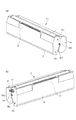
引き出し部材170について、図15乃至図17を用いて説明する。
図15(a)は引き出し部材170を右斜め上方より見た斜視図、図15(b)は同じく左斜めより見た斜視図である。図16(a)は引き出し部材170の縦断右側面図、図16(b)は同じく縦断左断面図である。
(Drawer member)
The
FIG. 15A is a perspective view of the
引き出し部材170の外側面には、装置本体200Aの左右のガイド溝部14に係合してガイドされる被ガイド部172R・172Lが設けられている。被ガイド部172R・172Lがガイド溝部14と係合して、引き出し部材170は略水平に前後方向に移動可能に支持される。
Guided
引き出し部材170は、カートリッジQを装着するための4つの装着部170a〜170dが前後方向に並んで設けられている。引き出し部材の装着方向D1の上流側から順に、第二の装着部である装着部170aと、第一の装着部である装着部170b、装着部170c、装着部170dが設けられる。装着部170aはカートリッジQyを装着するためのもの、装着部170bはカートリッジQmを装着するためのもの、装着部170cはカートリッジQcを装着するためのもの、装着部170dはカートリッジQkを装着するためのものである。装着部170a〜170dの間には、仕切り板170eが設けられている。装着部170a〜170dの下部には、開口部170fが設けられている。カートリッジQのドラム1が、開口部170fを通じて転写ベルト150および記録媒体Sと接触する。
The
各装着部170a〜170dの左右両側面には、カートリッジQを引き出し部材170内に装着するためのガイド手段175が設けられている。装着部170aの右側面にはガイド部175a1・175a3が、左側面にはガイド部175a2・175a4がそれぞれ設けられる。175a1は175a3と、175a2は175a4と、それぞれ対向している。以下同様に、装着部170bの両端にはガイド部175b1〜175b4が、装着部170cの両端にはガイド部175c1〜175c4が、装着部170dの両端にはガイド部175d1〜175d4が、それぞれ設けられる。
Guide means 175 for mounting the cartridge Q in the
本実施例では、前側の3つの装着部170a〜170cのガイド部175a〜175cについては、それぞれ共通の形状としている。一方、最も後側、引き出し方向D2における最も上流側、に位置する装着部170dのガイド部175dについては、ガイド部175a〜175cと異なる形状としている。ガイド部175d1・175d2は、上下2つの直線状の部位の組み合わせにより構成され、下部はガイド部175d1・175d2の下端から斜め後ろ方向(E3方向)に延びており、上部は斜め前方向(E4方向)へ延びた形状としている。また、ガイド部175d3・175d4は、上下2つの直線形状の組み合わせによって構成される。ガイド部175d3・175d4の下部はガイド部175d1・175d2の下部と平行である。
In this embodiment, the guide portions 175a to 175c of the three front mounting
図17において、L1およびL2は、ガイド部175c1および175d1について、ガイド部上端と下端との水平寸法をあらわす。ガイド部175d1は、L2がL1より大きくなるよう構成されている。 In FIG. 17, L1 and L2 indicate the horizontal dimensions of the upper end and the lower end of the guide portion with respect to the guide portions 175c1 and 175d1. The guide portion 175d1 is configured such that L2 is larger than L1.
引き出し部材170の装着部170dのさらに後側には、凹部170gが設けられる。本実施例においては、引き出し部材170dの後端面に、断面が三角形の凹部170gとして形成される。
A
引き出し部材170の後端面の上部に、規制部170hを設ける。凹部170gおよび装着部170dの上部の空間に延在し、画像形成装置の開口部100aを通過可能な高さで、2つの規制部170hが形成される。
A restricting
(カートリッジ)
引き出し部材170に装着される(支持される)カートリッジQについて図12(b)および図18を用いて説明する。代表してカートリッジQyの外観斜視図を図18にしめす。4つのカートリッジQy・Qm・Qc・Qkは、収容している現像剤の色が異なる以外の構成は同じである。カートリッジQを構成する各部材については、実施例1に記載のカートリッジPと同様である。
(cartridge)
The cartridge Q mounted (supported) on the
(引き出し部材へのカートリッジの装着)
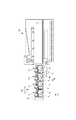
引き出し部材170へのカートリッジQ(Qy・Qm・Qc・Qk)の装着について、図14および図19(a)〜(c)を用いて説明する。図14は、引き出し部材170を装置本体200Aから所定位置まで引き出して、カートリッジQmを取り出す途中の状態の画像形成装置200の縦断右断面図である。図19(a)(b)(c)は、装置本体200Aから引き出し部材170の最も後側に装着されたカートリッジQkを取り出す過程を示した画像形成装置200の縦断右断面図である。
(Mounting the cartridge to the drawer member)
Mounting of the cartridge Q (Qy, Qm, Qc, Qk) on the
図14および図19はすべて、引き出し部材170を所定位置まで引き出した状態を示す。引き出し部材170が所定位置まで引き出したとき、引き出し方向D2において最も上流側に支持されたカートリッジQkは、カートリッジQkの一部(感光体ユニット8の一部)が装置本体200Aの内側に位置している。この状態で、カートリッジQkをカートリッジQy・Qm・Qcと同様にE2方向へ移動させると、装置本体200Aと干渉しカートリッジQkを取り出すことができない。
14 and 19 all show a state in which the
本実施例のガイド部175dによれば、カートリッジQkは以下の動作によって引き出し部材170から取り出される。引き出し部材170を所定位置まで引き出した図19(a)の状態から、ユーザはカートリッジQkの把持部65をつかみ上方へ引き上げる。すると、被ガイド部63p〜63sが係合するガイド部175d1〜175d4にガイドされて、カートリッジQkは後方向にずれながら上方へ移動する(E3方向)。このとき、引き出し部材170に設けた凹部170gに、カートリッジQkの一部(感光体ユニット8の一部)が進入する。
According to the guide portion 175d of this embodiment, the cartridge Qk is taken out from the
次に、被ガイド部63r・63sが係合するガイド部175d3・175d4の向きが変わるため、カートリッジQkは図19(b)に示すように反時計方向に回動しながら上方へ移動する。このとき、カートリッジQkが凹部170gに進入している。凹部170gは、カートリッジQkが回動するためのスペースを有するよう構成される。図19(b)は、カートリッジQkがガイド部175d1〜175d4にガイドされて回動し終えた状態である。この時点で、被ガイド部63r・63sとガイド部175d3・175d4との係合が解除される。この状態において、規制部材170hがカートリッジQk(感光体ユニット8の後端面)に平行かつ近接するよう規制部材170hが構成される。即ち、ガイド部175d3・175d4は、カートリッジQkを装着部170dより取り外す際に、カートリッジQkの引き出し方向D2への移動量がそれ以外のカートリッジQy、Qc、Qmの引き出し方向への移動量より大きくなるよう構成されることになる。
Next, since the directions of the guide portions 175d3 and 175d4 with which the guided
続いて、カートリッジQkは、被ガイド部63p・63qがガイド部175d1・175d2に係合してガイドされ、かつ、感光体ユニット8の後端面が規制部材170hに近接されることで、カートリッジQkの回動をおさえながら斜め上方へ引き上げられる。前述の通り、被ガイド部63p・63qとガイド部175d1・175d2との係合が解除される位置は、ガイド部175dをガイド部175a〜175cと共通の形状とした場合の係合解除位置より前側となる。
Subsequently, the cartridge Qk is guided by engaging the guided
引き出し部材の引き出し量が大きいと、画像形成装置の重量バランスが不安定になり、装置が傾くなどのおそれがある。そこで、本実施例の構成によれば、引き出し部材の引き出し量を少なくした装置本体においても、実施例1同様に、引き出し方向の上流側に支持されたカートリッジを、より前側で引き出し部材と係合させることができる。 If the pull-out amount of the pull-out member is large, the weight balance of the image forming apparatus becomes unstable and the apparatus may be inclined. Therefore, according to the configuration of the present embodiment, even in the apparatus main body in which the pull-out amount of the pull-out member is reduced, the cartridge supported on the upstream side in the pull-out direction is engaged with the pull-out member on the front side as in the first embodiment. Can be made.
カートリッジQkのように、カートリッジQを回動させて方向転換したうえでより前方へ引き上げるには、装着部の後側にスペースが必要となる。ガイド部175dの構成を4つの装着部170a〜dすべてで実施すると、引き出し部材が大型化、ひいては画像形成装置が大型化するおそれがある。ただし、引き出し部材170の後端部、すなわち引き出し方向の最も上流側の装着部170dの後側は、引き出し部材170が移動するスペースであり、引き出し部材170を所定位置まで引き出した状態では、デッドスペースとなる。そのため、このスペースを利用して最も後側のカートリッジQkを回動させたとしても、引き出し部材170や画像形成装置200の大型化にはつながらない。引き出し部材170を小型化して、たとえば板金によって引き出し部材170を形成した場合、後端面の所定位置に開口部を設けることで、本実施例の凹部170gの機能を果たすことが可能である。よって、引き出し方向の最も上流側の装着部170dおよびガイド部175dのみを本実施例に示す構成とすることが望ましい。
Like the cartridge Qk, in order to rotate the cartridge Q to change its direction and then pull it forward, a space is required on the rear side of the mounting portion. If the configuration of the guide portion 175d is implemented by all the four mounting
(まとめ)
引き出し方向における最も上流側のガイド部を実施例1および実施例2で述べたような構成とすることで、カートリッジ装着時にカートリッジをより前側からガイドすること、および、カートリッジ取り出し時にカートリッジをより前側までガイドすることができる。これによって、引き出し方向最上流側に支持されたカートリッジ着脱の際の操作性向上、およびカートリッジの有するプロセス部材をカートリッジ着脱の際に損傷しにくくすることができる。
(Summary)
By configuring the most upstream guide portion in the pull-out direction as described in the first and second embodiments, the cartridge is guided from the front side when the cartridge is mounted, and the cartridge is moved to the front side when the cartridge is taken out. Can guide. As a result, it is possible to improve the operability when attaching / detaching the cartridge supported on the most upstream side in the pulling direction, and to prevent the process member of the cartridge from being damaged when attaching / detaching the cartridge.
100 カラー電子写真画像形成装置
70 引き出し部材
70a/70b/70c/70d 装着部
75a1〜a4/75b1〜b4/75c1〜c4/75d1〜d4 ガイド部
P(Py/Pm/Pc/Pk) カートリッジ
DESCRIPTION OF
Claims (17)
第一のカートリッジ及び第二のカートリッジを支持した状態で、前記画像形成装置の装置本体の内側に位置する内側位置と、前記内側位置から引き出し方向に移動することで前記装置本体の外側へ引き出された引き出し位置と、の間を移動可能なカートリッジ支持部材と、
前記カートリッジ支持部材に設けられた、前記第一のカートリッジが装着される第一の装着部と、
前記カートリッジ支持部材に設けられ、前記引き出し方向に関して前記第一の装着部よりも上流側に配置された、前記第二のカートリッジが装着される第二の装着部と、
前記カートリッジ支持部材に設けられた、前記第一の装着部に対して前記第一のカートリッジを着脱可能に案内する第一のガイド部と、
前記カートリッジ支持部材に設けられた、前記第二の装着部に対して前記第二のカートリッジを着脱可能に案内する第二のガイド部と、を有し、
前記第一のカートリッジが前記第一の装着部に装着された状態で、前記第二のカートリッジは前記第二のガイド部で案内されながら前記引き出し方向の下流側へ移動することにより前記第二の装着部から取り外し可能であり、
前記第二のカートリッジを前記第二の装着部より取り外す際に、前記第二のカートリッジが前記第二のガイド部に案内されながら前記引き出し方向の下流側へ移動する移動量が、前記第一のカートリッジを前記第一の装着部より取り外す際に、前記第一のガイド部に案内されている前記第一のカートリッジの前記引き出し方向の下流側への移動量より大きいことを特徴とする画像形成装置。 In an image forming apparatus for forming an image on a recording medium,
With the first cartridge and the second cartridge supported, the inner position positioned inside the apparatus main body of the image forming apparatus, and the outer side of the apparatus main body is pulled out from the inner position by moving in the pulling direction. a position out can pull was a cartridge supporting member movable between,
A first mounting portion provided on the cartridge support member to which the first cartridge is mounted;
A second mounting portion provided on the cartridge support member and disposed on the upstream side of the first mounting portion with respect to the pulling direction;
A first guide portion provided on the cartridge support member for removably guiding the first cartridge with respect to the first mounting portion;
A second guide portion provided on the cartridge support member for removably guiding the second cartridge with respect to the second mounting portion ;
With the first cartridge mounted in the first mounting portion, the second cartridge moves to the downstream side in the pulling-out direction while being guided by the second guide portion. It can be removed from the mounting part,
When the second cartridge is removed from the second mounting portion, the movement amount of the second cartridge moving downstream in the pulling direction while being guided by the second guide portion is the first cartridge. the cartridge upon removal from the first mounting portion, the image forming characterized by the us go magnitude than the movement amount to the drawing direction of the downstream side of the first cartridge being guided by the first guide portion apparatus.
前記第二の装着部に装着された前記第二のカートリッジに設けられた、前記第二のカートリッジを前記装着部より取り外す際に把持する第二の把持部は、前記第一の装着部に装着された前記第一のカートリッジに設けられた、前記第一のカートリッジを前記第一の装着部より取り外す際に把持する第一の把持部よりも前記引き出し方向において下流側へ大きく傾斜していることを特徴とする請求項1乃至11のいずれか1項に記載の画像形成装置。 The cartridge support member includes the first cartridge and the second cartridge,
A second grip portion provided on the second cartridge mounted on the second mounting portion for gripping the second cartridge from the mounting portion is mounted on the first mounting portion. The first cartridge, which is provided in the first cartridge, is inclined more to the downstream side in the pull-out direction than the first holding portion that holds the first cartridge when it is removed from the first mounting portion. the image forming apparatus according to any one of claims 1 to 11, wherein the.
前記カートリッジ支持部材が前記内側位置にあるときに、前記カートリッジ支持部材に設けられた複数の感光体からトナー像が転写される転写手段を有することを特徴とする請求項1乃至14のいずれか1項に記載の画像形成装置。 The image forming apparatus includes:
When said cartridge supporting member is in the inside position, any one of claims 1 to 14 the toner images of a plurality of photosensitive body provided in the cartridge support member and having a transfer means to be transferred 1 The image forming apparatus described in the item.
前記カートリッジ支持部材が前記内側位置にあるときに、前記カートリッジ支持部材に設けられた複数の感光体からトナー像が転写される記録媒体を搬送する搬送手段を有することを特徴とする請求項1乃至14のいずれか1項に記載の画像形成装置。 The image forming apparatus includes:
2. A conveying unit configured to convey a recording medium onto which a toner image is transferred from a plurality of photosensitive members provided on the cartridge supporting member when the cartridge supporting member is in the inner position. The image forming apparatus according to any one of 14 .
Priority Applications (3)
| Application Number | Priority Date | Filing Date | Title |
|---|---|---|---|
| JP2011110619A JP5836639B2 (en) | 2011-05-17 | 2011-05-17 | Image forming apparatus |
| US13/472,808 US8855531B2 (en) | 2011-05-17 | 2012-05-16 | Image forming apparatus with removable cartridge supporting member |
| US14/474,628 US9429900B2 (en) | 2011-05-17 | 2014-09-02 | Cartridge supporting member having different moving direction guide portions |
Applications Claiming Priority (1)
| Application Number | Priority Date | Filing Date | Title |
|---|---|---|---|
| JP2011110619A JP5836639B2 (en) | 2011-05-17 | 2011-05-17 | Image forming apparatus |
Publications (3)
| Publication Number | Publication Date |
|---|---|
| JP2012242501A JP2012242501A (en) | 2012-12-10 |
| JP2012242501A5 JP2012242501A5 (en) | 2014-07-03 |
| JP5836639B2 true JP5836639B2 (en) | 2015-12-24 |
Family
ID=47175009
Family Applications (1)
| Application Number | Title | Priority Date | Filing Date |
|---|---|---|---|
| JP2011110619A Expired - Fee Related JP5836639B2 (en) | 2011-05-17 | 2011-05-17 | Image forming apparatus |
Country Status (2)
| Country | Link |
|---|---|
| US (2) | US8855531B2 (en) |
| JP (1) | JP5836639B2 (en) |
Cited By (1)
| Publication number | Priority date | Publication date | Assignee | Title |
|---|---|---|---|---|
| JP2883462B2 (en) | 1991-04-01 | 1999-04-19 | 株式会社東芝 | Purification system |
Families Citing this family (18)
| Publication number | Priority date | Publication date | Assignee | Title |
|---|---|---|---|---|
| JP5653127B2 (en) | 2010-08-19 | 2015-01-14 | キヤノン株式会社 | Image forming apparatus |
| JP5896963B2 (en) * | 2013-08-20 | 2016-03-30 | キヤノン株式会社 | Image forming apparatus and process cartridge |
| JP5805155B2 (en) * | 2013-08-20 | 2015-11-04 | キヤノン株式会社 | Image forming apparatus |
| JP5805156B2 (en) | 2013-08-20 | 2015-11-04 | キヤノン株式会社 | Image forming apparatus |
| JP6373078B2 (en) * | 2014-06-13 | 2018-08-15 | キヤノン株式会社 | Image forming apparatus |
| JP6643052B2 (en) * | 2014-11-28 | 2020-02-12 | キヤノン株式会社 | Image forming device |
| JP6481395B2 (en) | 2015-02-06 | 2019-03-13 | ブラザー工業株式会社 | Image forming apparatus |
| JP6409603B2 (en) | 2015-02-06 | 2018-10-24 | ブラザー工業株式会社 | Image forming apparatus |
| JP6645683B2 (en) | 2015-05-21 | 2020-02-14 | キヤノン株式会社 | Image forming apparatus and cartridge used therein |
| JP7187166B2 (en) * | 2017-05-18 | 2022-12-12 | キヤノン株式会社 | image forming device |
| JP7006150B2 (en) * | 2017-11-10 | 2022-01-24 | ブラザー工業株式会社 | Image forming device |
| JP7081325B2 (en) | 2018-06-19 | 2022-06-07 | ブラザー工業株式会社 | Image forming device |
| JP2020046513A (en) * | 2018-09-18 | 2020-03-26 | ブラザー工業株式会社 | Image forming device |
| JP2020046644A (en) | 2018-09-21 | 2020-03-26 | ブラザー工業株式会社 | Image forming apparatus |
| JP6992720B2 (en) * | 2018-09-27 | 2022-01-13 | 沖電気工業株式会社 | Image forming device |
| JP7347150B2 (en) * | 2019-11-18 | 2023-09-20 | ブラザー工業株式会社 | Image forming device |
| JP7651257B2 (en) * | 2019-12-27 | 2025-03-26 | キヤノン株式会社 | Image forming device |
| JP7596772B2 (en) * | 2020-12-18 | 2024-12-10 | ブラザー工業株式会社 | Image forming device |
Family Cites Families (25)
| Publication number | Priority date | Publication date | Assignee | Title |
|---|---|---|---|---|
| JPH1026863A (en) | 1996-07-10 | 1998-01-27 | Canon Inc | Image forming device |
| JP2001066968A (en) | 1999-08-31 | 2001-03-16 | Canon Inc | Image forming device |
| JP3981518B2 (en) | 2000-08-25 | 2007-09-26 | 株式会社リコー | Image forming apparatus |
| JP2002207408A (en) | 2001-01-10 | 2002-07-26 | Canon Inc | Electrophotographic image forming apparatus and process cartridge |
| US7778567B2 (en) | 2004-09-29 | 2010-08-17 | Brother Kogyo Kabushiki Kaisha | Image forming apparatus and image forming unit |
| JP4161952B2 (en) | 2004-09-29 | 2008-10-08 | ブラザー工業株式会社 | Image forming apparatus |
| JP4655924B2 (en) * | 2005-12-27 | 2011-03-23 | ブラザー工業株式会社 | Developing unit and image forming apparatus having the same |
| JP4769699B2 (en) | 2006-01-11 | 2011-09-07 | キヤノン株式会社 | Electrophotographic image forming apparatus |
| JP4760395B2 (en) | 2006-01-19 | 2011-08-31 | ブラザー工業株式会社 | Cartridge and image forming apparatus |
| JP4928839B2 (en) | 2006-06-12 | 2012-05-09 | 株式会社リコー | Image forming apparatus |
| JP4882593B2 (en) * | 2006-08-17 | 2012-02-22 | 富士ゼロックス株式会社 | Image forming apparatus |
| JP4356035B2 (en) * | 2008-11-04 | 2009-11-04 | ブラザー工業株式会社 | Image forming apparatus |
| JP4334014B1 (en) * | 2008-12-18 | 2009-09-16 | キヤノン株式会社 | Color electrophotographic image forming apparatus |
| JP4384251B1 (en) | 2009-03-11 | 2009-12-16 | キヤノン株式会社 | Developing cartridge, process cartridge, and electrophotographic image forming apparatus |
| JP4562208B1 (en) | 2009-03-23 | 2010-10-13 | キヤノン株式会社 | Color electrophotographic image forming apparatus |
| JP4605821B2 (en) | 2009-03-23 | 2011-01-05 | キヤノン株式会社 | Electrophotographic image forming apparatus |
| JP4721471B2 (en) | 2009-03-23 | 2011-07-13 | キヤノン株式会社 | Electrophotographic image forming apparatus |
| JP4569977B1 (en) | 2009-03-23 | 2010-10-27 | キヤノン株式会社 | Electrophotographic image forming apparatus |
| JP4569978B1 (en) | 2009-03-23 | 2010-10-27 | キヤノン株式会社 | Color electrophotographic image forming apparatus |
| JP4846033B2 (en) | 2009-03-26 | 2011-12-28 | キヤノン株式会社 | Electrophotographic image forming apparatus |
| JP5220084B2 (en) | 2009-12-11 | 2013-06-26 | キヤノン株式会社 | Electrophotographic image forming apparatus |
| JP4678891B1 (en) | 2010-07-05 | 2011-04-27 | キヤノン株式会社 | Electrophotographic image forming apparatus |
| JP5653127B2 (en) | 2010-08-19 | 2015-01-14 | キヤノン株式会社 | Image forming apparatus |
| JP5350455B2 (en) | 2010-12-16 | 2013-11-27 | キヤノン株式会社 | Electrophotographic image forming apparatus |
| JP5805155B2 (en) * | 2013-08-20 | 2015-11-04 | キヤノン株式会社 | Image forming apparatus |
-
2011
- 2011-05-17 JP JP2011110619A patent/JP5836639B2/en not_active Expired - Fee Related
-
2012
- 2012-05-16 US US13/472,808 patent/US8855531B2/en active Active
-
2014
- 2014-09-02 US US14/474,628 patent/US9429900B2/en active Active
Cited By (1)
| Publication number | Priority date | Publication date | Assignee | Title |
|---|---|---|---|---|
| JP2883462B2 (en) | 1991-04-01 | 1999-04-19 | 株式会社東芝 | Purification system |
Also Published As
| Publication number | Publication date |
|---|---|
| US9429900B2 (en) | 2016-08-30 |
| US8855531B2 (en) | 2014-10-07 |
| US20120294646A1 (en) | 2012-11-22 |
| US20140369714A1 (en) | 2014-12-18 |
| JP2012242501A (en) | 2012-12-10 |
Similar Documents
| Publication | Publication Date | Title |
|---|---|---|
| JP5836639B2 (en) | Image forming apparatus | |
| JP4709133B2 (en) | Electrophotographic image forming apparatus | |
| JP4334014B1 (en) | Color electrophotographic image forming apparatus | |
| JP4592113B2 (en) | Color electrophotographic image forming apparatus | |
| JP5220084B2 (en) | Electrophotographic image forming apparatus | |
| JP4818461B2 (en) | Electrophotographic image forming apparatus | |
| JP5414171B2 (en) | Image forming apparatus | |
| CN106909044B (en) | Image forming apparatus with a plurality of image forming units | |
| JP6128754B2 (en) | Image forming apparatus | |
| JP6112839B2 (en) | Image forming apparatus | |
| JP5627317B2 (en) | Color electrophotographic image forming apparatus and photosensitive member cartridge | |
| US7983597B2 (en) | Color electrophotographic image forming apparatus with gripping portions for cartridges | |
| US20130243470A1 (en) | Color electrophotographic image forming apparatus | |
| JP2014106392A (en) | Image forming apparatus | |
| JP5241138B2 (en) | Electrophotographic image forming apparatus | |
| JP2018081194A (en) | Image forming apparatus | |
| JP2010122661A (en) | Image forming apparatus | |
| JP5627309B2 (en) | Color electrophotographic image forming apparatus, cartridge, developing cartridge | |
| JP2010224117A (en) | Color electrophotographic image forming apparatus | |
| JP6602051B2 (en) | Image forming apparatus | |
| JP2017167523A (en) | Image forming apparatus | |
| JP2011033924A (en) | Cartridge and electrophotographic image forming apparatus | |
| JP4769699B2 (en) | Electrophotographic image forming apparatus | |
| JP5430784B2 (en) | Electrophotographic image forming apparatus | |
| JP2014102522A (en) | Image forming apparatus |
Legal Events
| Date | Code | Title | Description |
|---|---|---|---|
| A521 | Request for written amendment filed |
Free format text: JAPANESE INTERMEDIATE CODE: A523 Effective date: 20140516 |
|
| A621 | Written request for application examination |
Free format text: JAPANESE INTERMEDIATE CODE: A621 Effective date: 20140516 |
|
| A977 | Report on retrieval |
Free format text: JAPANESE INTERMEDIATE CODE: A971007 Effective date: 20150320 |
|
| A131 | Notification of reasons for refusal |
Free format text: JAPANESE INTERMEDIATE CODE: A131 Effective date: 20150324 |
|
| A521 | Request for written amendment filed |
Free format text: JAPANESE INTERMEDIATE CODE: A523 Effective date: 20150525 |
|
| TRDD | Decision of grant or rejection written | ||
| A01 | Written decision to grant a patent or to grant a registration (utility model) |
Free format text: JAPANESE INTERMEDIATE CODE: A01 Effective date: 20151006 |
|
| A61 | First payment of annual fees (during grant procedure) |
Free format text: JAPANESE INTERMEDIATE CODE: A61 Effective date: 20151104 |
|
| R151 | Written notification of patent or utility model registration |
Ref document number: 5836639 Country of ref document: JP Free format text: JAPANESE INTERMEDIATE CODE: R151 |
|
| LAPS | Cancellation because of no payment of annual fees |