JP5824699B2 - Game machine - Google Patents

Game machine Download PDF

Info

Publication number
JP5824699B2
JP5824699B2 JP2013186385A JP2013186385A JP5824699B2 JP 5824699 B2 JP5824699 B2 JP 5824699B2 JP 2013186385 A JP2013186385 A JP 2013186385A JP 2013186385 A JP2013186385 A JP 2013186385A JP 5824699 B2 JP5824699 B2 JP 5824699B2
Authority
JP
Japan
Prior art keywords
decorative body
effect
element member
move
decoration
Prior art date
Legal status (The legal status is an assumption and is not a legal conclusion. Google has not performed a legal analysis and makes no representation as to the accuracy of the status listed.)
Active
Application number
JP2013186385A
Other languages
Japanese (ja)
Other versions
JP2014061336A (en
JP2014061336A5 (en
Inventor
平野 泰弘
泰弘 平野
Original Assignee
株式会社サンセイアールアンドディ
Priority date (The priority date is an assumption and is not a legal conclusion. Google has not performed a legal analysis and makes no representation as to the accuracy of the date listed.)
Filing date
Publication date
Application filed by 株式会社サンセイアールアンドディ filed Critical 株式会社サンセイアールアンドディ
Priority to JP2013186385A priority Critical patent/JP5824699B2/en
Publication of JP2014061336A publication Critical patent/JP2014061336A/en
Publication of JP2014061336A5 publication Critical patent/JP2014061336A5/ja
Application granted granted Critical
Publication of JP5824699B2 publication Critical patent/JP5824699B2/en
Active legal-status Critical Current
Anticipated expiration legal-status Critical

Links

Images

Description

本発明は、所定の動作を行う演出用の部材を備えたパチンコ遊技機に関する。   The present invention relates to a pachinko gaming machine provided with a staging member that performs a predetermined operation.

例えば特許文献1には、遊技を演出する目的で、センター役物の周囲に可動演出装置を設けたものが記載されている。可動演出装置としては、電気的駆動源により可動部材が基準位置から落下したり上昇したりして遊技を演出するものが例示できる。   For example, Patent Document 1 describes a device in which a movable effect device is provided around a center accessory for the purpose of producing a game. Examples of the movable effect device include a device that produces a game by moving or dropping a movable member from a reference position by an electric drive source.

特開2007−244666号公報JP 2007-244666 A

ところで、このような遊技機の中に、複数の可動演出装置を備えるものがある。このような複数の可動演出装置を備えるものには、複数の可動演出装置がそれぞれ独立した動きをするものや、複数の可動部材が合体して一つの形態を構成するものなどがある。しかし、複数の可動部材等の組み合わせによって構成される演出形態が、少なくとも一つの部材の位置を変えることで複数の演出形態を構成できるものがなく、演出効果が単調なものになっていた。   By the way, some of such gaming machines include a plurality of movable effect devices. Examples of the apparatus including a plurality of movable effect devices include a device in which the plurality of movable effect devices move independently, and a device in which a plurality of movable members are combined to form one form. However, there is no effect form constituted by a combination of a plurality of movable members or the like that can form a plurality of effect forms by changing the position of at least one member, and the effect is monotonous.

上記実情に鑑み、本発明が解決しようとする課題は、複数の可動部材等の組み合わせによって演出を行う際に、少なくとも一つの部材の位置を変えて複数の演出形態を構成することで、複数の演出形態による優れた演出効果を発現する遊技機を提供することである。   In view of the above situation, the problem to be solved by the present invention is to produce a plurality of presentation forms by changing the position of at least one member when performing a presentation by a combination of a plurality of movable members and the like. It is to provide a gaming machine that exhibits an excellent production effect by a production form.

上記課題を解決するためになされた請求項1の発明にかかる遊技機は、遊技状態に応じた装飾を行う第一装飾体及び第二装飾体と、遊技領域に遊技者にとって視認可能に配置され、第一演出位置と第二演出位置との間を移動可能な演出体と、を備え、前記第一装飾体は前記第一演出位置や前記第二演出位置とは異なる第一位置と第二位置との間を移動可能であり、前記第二装飾体は前記第一演出位置や前記第二演出位置とは異なる第三位置と第四位置との間を移動可能であり、前記第一演出位置に位置する前記演出体と前記第二位置に位置する前記第一装飾体との組み合わせで第一演出状態が構成され、前記第二演出位置に位置する前記演出体と前記第四位置に位置する前記第二装飾体との組み合わせで前記第一演出状態と異なる第二演出状態が構成され、前記第一装飾体が前記第一位置から前記第二位置に移動することで、前記第一装飾体によって前記第一演出位置に位置する前記演出体の少なくとも一部を収納可能な第一収納部を形成する一方、前記第二装飾体が前記第三位置から前記第四位置に移動すると共に前記第一装飾体が前記第一位置から前記第二位置に移動することで、前記第二装飾体と前記第一装飾体によって前記第二演出位置に位置する前記演出体の少なくとも一部を収納可能な第二収納部を形成することを特徴とする。 A gaming machine according to the invention of claim 1, which has been made to solve the above-mentioned problems, is arranged so that a player can visually recognize a first decorative body and a second decorative body that perform decoration according to a gaming state, and a game area. An effector movable between the first effect position and the second effect position, wherein the first decorative body is different from the first effect position and the second effect position in the first position and the second effect position. The second decoration body is movable between a third position and a fourth position different from the first effect position and the second effect position, and the first effect The first effect state is configured by a combination of the effect body located at the position and the first decorative body located at the second position, and is located at the effect position located at the second effect position and the fourth position. A second performance form that is different from the first performance state in combination with the second decorative body There is constructed, the by first decorative body is moved to said second position from said first position, capable of housing at least part of the presentation member positioned in the first effect position by said first decorative body While forming the first storage portion, the second decorative body moves from the third position to the fourth position and the first decorative body moves from the first position to the second position. The second decorative body and the first decorative body form a second storage portion that can store at least a part of the effect body located at the second effect position .

請求項の発明は、請求項に記載の遊技機において、前記第二位置に位置する前記第一装飾体と前記第四位置に位置する前記第二装飾体との組み合わせで第三演出状態が構成されるところに特徴を有する。 According to a second aspect of the invention, in the gaming machine according to claim 1, in combination with the third effect state between the second decorative body located in said second position to a position wherein the first decoration member and the fourth position It is characterized in that is constructed.

請求項の発明は、請求項または請求項に記載の遊技機において、前記第一装飾体が前記第一位置に位置すると共に前記第二装飾体が前記第三位置に位置している状態においては、前記第一演出位置と前記第二演出位置の間の前記演出体の移動が可能である一方、前記第一装飾体が前記第二位置に位置するか、または、前記第二装飾体が前記第四位置に位置することで、前記第一演出位置と前記第二演出位置の間の前記演出体の移動を規制する移動規制部が構成されるところに特徴を有する。 According to a third aspect of the present invention, in the gaming machine according to the first or second aspect , the first decorative body is located at the first position and the second decorative body is located at the third position. In the state, the effect body can be moved between the first effect position and the second effect position, while the first ornament is located at the second position or the second ornament. It is characterized in that a movement restricting unit that restricts movement of the effector between the first effect position and the second effect position is configured by the body being located at the fourth position.

請求項の発明は、請求項に記載の遊技機において、前記第一装飾体を前記第一位置から前記第二位置へ移動させようとする際に、前記演出体が前記第一演出位置に位置するときには、前記演出体を前記第一演出位置から前記第二演出位置へと移動させてから前記第一装飾体を前記第一位置から前記第二位置へ移動させるか、または、前記演出体を前記第一演出位置に位置させたまま前記第一装飾体のみを前記第一位置から前記第二位置へ移動させ、前記第一装飾体を前記第二位置から前記第一位置へ移動させようとする際に、前記演出体が前記第二演出位置に位置するときには、前記第一装飾体を前記第二位置から前記第一位置へと移動させてから前記演出体を前記第二演出位置から前記第一演出位置へ移動させるか、または、前記演出体を前記第二演出位置に位置させたまま前記第一装飾体のみを前記第二位置から前記第一位置へ移動させるように制御する制御手段を備えるところに特徴を有する。 The invention according to claim 4 is the gaming machine according to claim 3 , wherein when the first decorative body is moved from the first position to the second position, the effect body is the first effect position. When the position is located, the effect body is moved from the first effect position to the second effect position and then the first decorative body is moved from the first position to the second position, or the effect is Only the first decorative body is moved from the first position to the second position while the body is positioned at the first performance position, and the first decorative body is moved from the second position to the first position. When trying, when the said effect body is located in said 2nd effect position, after moving said 1st decoration body from said 2nd position to said 1st position, said effect body is made into said 2nd effect position. Move to the first production position or the production The has a feature where the control means for controlling so as to move only the first decorative body while keeping the position in the second presentation position to said first position from said second position.

請求項の発明は、請求項から請求項のいずれか一項に記載の遊技機において、前記第一装飾体は、同一の駆動源で動作する複数の要素部材から構成されるとともに、前記第二装飾体は、同一の駆動源で動作する前記第一装飾体を構成する要素部材と同数の要素部材から構成され、前記第一装飾体を構成する各要素部材は、予め定められた対応する前記第二装飾体を構成する一の要素部材と一体的な状態を構成するところに特徴を有する。 A fifth aspect of the present invention, in the gaming machine according to any one of claims 1 to 4, wherein the first decoration member, along which a plurality of element members operating at the same driving source, The second decorative body is composed of the same number of element members as the constituent elements of the first decorative body that operate with the same drive source, and each element member that configures the first decorative body is predetermined. It is characterized in that it constitutes an integral state with one element member constituting the corresponding second decorative body.

請求項に記載の発明は、請求項に記載の発明において、前記第一装飾体を構成する各要素部材は、前記第一装飾体が第一位置から第二位置に移動しようとする際には、予め定められた移動順通りに、ある要素部材が第一位置から第二位置まで移動し終えてから、次の要素部材の第一位置から第二位置までの移動が行われるように構成される一方、前記第一装飾体が第二位置から第一位置に移動しようとする際には、前記移動順とは逆の順で、ある要素部材が第二位置から第一位置まで移動し終えてから、次の要素部材の第二位置から第一位置までの移動が行われるように構成されるところに特徴を有する。 The invention according to claim 6 is the invention according to claim 5 , wherein each element member constituting the first decorative body is configured such that the first decorative body is about to move from the first position to the second position. In order that the movement from the first position to the second position of the next element member is performed after a certain element member has finished moving from the first position to the second position in accordance with a predetermined movement order. On the other hand, when the first decorative body tries to move from the second position to the first position, an element member moves from the second position to the first position in the reverse order of the movement order. It is characterized in that it is configured to move the next element member from the second position to the first position after finishing.

請求項の発明は、請求項または請求項に記載の遊技機において、前記第二装飾体を構成する各要素部材は、前記第二装飾体が第三位置から第四位置に移動しようとする際には、予め定められた移動順通りに、ある要素部材が第三位置から第四位置まで移動し終えてから、次の要素部材の第三位置から第四位置までの移動が行われるように構成される一方、前記第二装飾体が第四位置から第三位置に移動しようとする際には、前記移動順とは逆の順で、ある要素部材が第四位置から第三位置まで移動し終えてから、次の要素部材の第四位置から第三位置までの移動が行われるように構成されるところに特徴を有する。 According to a seventh aspect of the present invention, in the gaming machine according to the fifth or sixth aspect , each element member constituting the second decorative body is such that the second decorative body moves from the third position to the fourth position. When a certain element member has finished moving from the third position to the fourth position according to a predetermined movement order, the next element member moves from the third position to the fourth position. On the other hand, when the second decorative body tries to move from the fourth position to the third position, an element member moves from the fourth position to the third position in the reverse order of the movement order. It is characterized in that the movement from the fourth position to the third position of the next element member is performed after the movement to the position is completed.

請求項の発明は、請求項に記載の遊技機において、前記第一装飾体を構成する各要素部材は、前記第一装飾体が第一位置から第二位置に移動しようとする際には、予め定められた移動順通りに、ある要素部材が第一位置から第二位置まで移動し終えてから、次の要素部材の第一位置から第二位置までの移動が行われるように構成される一方、前記第一装飾体が第二位置から第一位置に移動しようとする際には、前記移動順とは逆の順で、ある要素部材が第二位置から第一位置まで移動し終えてから、次の要素部材の第二位置から第一位置までの移動が行われるように構成され、前記第二装飾体を構成する各要素部材は、前記第二装飾体が第三位置から第四位置に移動しようとする際には、予め定められた移動順通りに、ある要素部材が第三位置から第四位置まで移動し終えてから、次の要素部材の第三位置から第四位置までの移動が行われるように構成される一方、前記第二装飾体が第四位置から第三位置に移動しようとする際には、前記移動順とは逆の順で、ある要素部材が第四位置から第三位置まで移動し終えてから、次の要素部材の第四位置から第三位置までの移動が行われるように構成され、前記第一装飾体を構成するある要素部材は、その要素部材の移動順と同じ移動順で動作する前記第二装飾体を構成する要素部材と一体的な形態を構成するところに特徴を有する。 The invention according to claim 8 is the gaming machine according to claim 5 , wherein each element member constituting the first decorative body is moved when the first decorative body is about to move from the first position to the second position. Is configured such that the movement of the next element member from the first position to the second position is performed after the movement of the certain element member from the first position to the second position in accordance with a predetermined movement order. On the other hand, when the first decorative body tries to move from the second position to the first position, an element member moves from the second position to the first position in the reverse order of the movement order. After completion, the second element member is configured to move from the second position to the first position, and each element member constituting the second decorative body has the second decorative body from the third position. When attempting to move to the fourth position, an element member is moved in the predetermined order of movement. The second element is configured to move from the third position to the fourth position of the next element member after the movement from the position to the fourth position, while the second decorative body is moved from the fourth position to the third position. When an element member is moved from the fourth position to the third position in the order opposite to the movement order, the fourth element position of the next element member is shifted from the fourth position to the third position. The element member constituting the first decorative body is integrated with the element member constituting the second decorative body that operates in the same movement order as the movement order of the element member. It has the feature in the form.

請求項の発明によれば、第一装飾体は、第一演出位置に位置する演出体(独立して動作する可動部材)と第一演出状態を構成し、第二装飾体は、第二演出位置に位置する演出体と第二演出状態を構成する。つまり、独立して動作する演出体が第一演出位置にあるか第二演出位置にあるかによって、異なる可動部材との組み合わせにより別の演出状態を構成することが可能であるから、幅広い演出効果を発現する遊技機となる。 According to invention of Claim 1, a 1st decoration body comprises the production body (movable member which operate | moves independently) located in a 1st production position, and a 1st production state, and a 2nd decoration body is 2nd. The effect body located in the effect position and the second effect state are configured. In other words, it is possible to configure different production states by combining different movable members depending on whether the production body that operates independently is in the first production position or the second production position, so a wide range of production effects It becomes a gaming machine that expresses.

また、第一装飾体が第一位置と第二位置の間を移動可能、第二装飾体が第三位置と第四位置の間を移動可能とした上で、第一演出位置に位置する演出体と第二位置に位置する第一装飾体との組み合わせで第一演出状態が構成され、第二演出位置に位置する演出体と第四位置に位置する第二装飾体との組み合わせで第二演出状態が構成されるようにすれば、第一装飾体、第二装飾体、および演出体によってより幅広い演出効果を発現することが可能となる。
また、第一装飾体によって第一演出位置に位置する演出体を収容することができる第一収納部、第一装飾体および第二装飾体によって第二演出位置に位置する演出体を収容することができる第二収納部が構成される構造、すなわち、遊技領域において第一装飾体や第二装飾体によって区画される領域(第一収納部および第二収納部)に演出体が入り込んだ状態とすることができる構造とすれば、限られた遊技領域を有効に活用して効果的な演出を行うことが可能となる。具体的には、第一装飾体および第二装飾体の少なくともいずれか一方と、演出体との合体動作による優れた演出効果が発現される。
In addition, the first decorative body is movable between the first position and the second position, and the second decorative body is movable between the third position and the fourth position, and the effect is located at the first effect position. The first effect state is configured by the combination of the body and the first decorative body located at the second position, and the combination of the effector positioned at the second effect position and the second decorative body positioned at the fourth position is the second. If the production state is configured, a wider production effect can be expressed by the first decoration body, the second decoration body, and the production body.
Moreover, accommodating the effect body located in the 2nd effect position by the 1st storage part which can accommodate the effect body located in the 1st effect position by the 1st decoration body, the 1st decoration body, and the 2nd decoration body. A structure in which the second storage unit is configured, that is, a state in which the production body enters the region (first storage unit and second storage unit) partitioned by the first decorative body and the second decorative body in the game area If the structure can be made, it is possible to effectively utilize a limited game area and perform an effective presentation. Specifically, an excellent performance effect is achieved by the combined operation of at least one of the first decorative body and the second decorative body and the rendering body.

請求項に記載の発明のように、第二位置に位置する第一装飾体と第四位置に位置する第二装飾体によって第三演出状態を構成するようにした場合には、第一装飾体と第二装飾体によってさらに幅広い演出効果を発現することが可能となる。 When the third effect state is constituted by the first decorative body positioned at the second position and the second decorative body positioned at the fourth position as in the invention described in claim 2 , A wider production effect can be expressed by the body and the second decorative body.

請求項の発明によれば、第一装飾体が第二位置に位置するか、または、第二装飾体が第四位置に位置している状態においては、第一演出位置と第二演出位置の間の演出体の移動を規制する移動規制部が構成されるため(各装飾体と演出体の動作が規制されるため)、第一装飾体および第二装飾体と演出体が干渉することを防止しつつ、種々の演出を行うことが可能となる。 According to the invention of claim 3 , in the state where the first decorative body is located at the second position or the second decorative body is located at the fourth position, the first effect position and the second effect position Because the movement restricting section that restricts the movement of the effector between the two is configured (because the operation of each ornamental body and the effector is restricted), the first ornamental body and the second ornamental body interfere with the effector. It is possible to perform various effects while preventing the problem.

請求項の発明によれば、上記制御手段を備えることにより(上記のように第一装飾体と演出体の動作を制御することにより)、第一装飾体と演出体が干渉することを防止しつつ、種々の演出を行うことが可能となる。 According to invention of Claim 4 , by providing the said control means (by controlling operation | movement of a 1st decoration body and a production body as mentioned above), it prevents that a 1st decoration body and a production body interfere. However, various effects can be performed.

請求項の発明によれば、第一装飾体および第二装飾体が、ともに、複数の要素部材から構成され、第一装飾体の要素部材と第二装飾体の要素部材が組み合わされて一体的な状態を構成する構造であるため、第一装飾体と第二装飾体によってなされる合体動作に様々な変化をもたらすことができる。換言すれば、複数種類の合体動作による演出を提供することが可能となる。 According to the invention of claim 5 , the first decorative body and the second decorative body are both composed of a plurality of element members, and the element members of the first decorative body and the element members of the second decorative body are combined and integrated. Therefore, various changes can be brought about in the combined operation performed by the first decorative body and the second decorative body. In other words, it is possible to provide effects by a plurality of types of coalescing operations.

請求項および請求項の発明によれば、第一装飾体または第二装飾体を構成するある要素部材が第一位置または第三位置から第二位置または第四位置に移動し終えてから次の要素部材の第一位置または第三位置から第二位置または第四位置までの移動が行われるように構成されるため、一の要素部材のみで状態を構成したり、複数の要素部材で状態を構成したりすることが可能となり、幅広い演出を提供することが可能となる。 According to invention of Claim 6 and Claim 7 , after a certain element member which comprises a 1st decoration body or a 2nd decoration body has finished moving from a 1st position or a 3rd position to a 2nd position or a 4th position. Since the next element member is configured to move from the first position or the third position to the second position or the fourth position, the state can be constituted by only one element member, or by a plurality of element members. The state can be configured, and a wide range of effects can be provided.

請求項の発明によれば、第一装飾体および第二装飾体を構成する複数の要素部材(第一要素部材〜第三要素部材)が、予め定められた移動順通りに移動し、同じ移動順の要素部材同士が一体的な状態を構成するため、ある一つの要素部材同士だけで一体的な状態を構成したり、複数の要素部材同士で一体的な状態を構成したりするなど、幅広い演出を提供することが可能となる。 According to the invention of claim 8 , the plurality of element members (first element member to third element member) constituting the first decorative body and the second decorative body move in a predetermined movement order and are the same. Since the element members in the movement order constitute an integral state, the integral state is constituted by only one element member, the integral state is constituted by a plurality of element members, etc. A wide range of performances can be provided.

本発明の一実施形態にかかる遊技機の正面図であり、第一装飾体が第二位置、第二装飾体が第四位置、演出体が第二演出位置に位置している状態を示したものである。It is a front view of the gaming machine concerning one embodiment of the present invention, and the state where the 1st decoration body is located in the 2nd position, the 2nd decoration body is located in the 4th position, and the production body is located in the 2nd production position. Is. 図1に示した遊技機が備える遊技盤の正面図であり、第一装飾体が第二位置、第二装飾体が第四位置、演出体が第二演出位置に位置している状態を示したものである。It is a front view of the game board with which the gaming machine shown in FIG. 1 is provided, and shows a state where the first decorative body is located at the second position, the second decorative body is located at the fourth position, and the effector is located at the second effect position. It is a thing. 第一装飾体(第一位置)、第二装飾体(第三位置)、および演出体(第一演出位置)が取り付けられた装置枠体の正面図である。It is a front view of the device frame to which the first decorative body (first position), the second decorative body (third position), and the effect body (first effect position) are attached. 装飾部材(第一装飾体および第二装飾体(これらの駆動源等を含む))の外観斜視図である。It is an external appearance perspective view of a decoration member (a 1st decoration body and a 2nd decoration body (these drive sources are included)). 図4におけるA部拡大図である。It is the A section enlarged view in FIG. 第一装飾体が第二位置、第二装飾体が第四位置に位置している状態における第一装飾体および第二装飾体(これらの駆動源等を含む)を前方から見た分解斜視図である。The exploded perspective view which looked at the 1st decoration body and the 2nd decoration body (including these drive sources etc.) from the front in the state where the 1st decoration body is located in the 2nd position and the 2nd decoration body is in the 4th position It is. 第一装飾体が第二位置、第二装飾体が第四位置に位置している状態における第一装飾体および第二装飾体(これらの駆動源等を含む)を後方から見た分解斜視図である。The exploded perspective view which looked at the 1st decoration body and the 2nd decoration body (including these drive sources etc.) from the back in the state where the 1st decoration body is located in the 2nd position and the 2nd decoration body is in the 4th position It is. 第一装飾体が第一位置、第二装飾体が第三位置に位置している状態における第一装飾体および第二装飾体(これらの駆動源等を含む)を前方から見た分解斜視図である。The exploded perspective view which looked at the 1st decoration body and the 2nd decoration body (including these drive sources etc.) from the front in the state where the 1st decoration body is located in the 1st position and the 2nd decoration body is located in the 3rd position It is. 第一装飾体が第一位置、第二装飾体が第三位置に位置している状態における第一装飾体および第二装飾体(これらの駆動源等を含む)を後方から見た分解斜視図である。The exploded perspective view which looked at the 1st decoration body and the 2nd decoration body (including these drive sources etc.) from the back in the state where the 1st decoration body is located in the 1st position and the 2nd decoration body is located in the 3rd position. It is. 第一装飾体が有する板状体(第一〜第三板状体)および第二装飾体が有する板状体(第一〜第三板状体)の拡大図である。It is an enlarged view of the plate-shaped body (first to third plate-shaped body) included in the first decorative body and the plate-shaped body (first to third plate-shaped body) included in the second decorative body. 第一装飾体の全ての要素部材が第二位置に位置している状態を示した図である。It is the figure which showed the state in which all the element members of a 1st decoration body are located in a 2nd position. 第一装飾体の第一要素部材および第二要素部材が第二位置に位置し、第一装飾体の第三要素部材が第一位置に位置している状態を示した図である。It is the figure which showed the state in which the 1st element member and 2nd element member of a 1st decoration body are located in a 2nd position, and the 3rd element member of a 1st decoration body is located in a 1st position. 第一装飾体の第一要素部材が第二位置に位置し、第一装飾体の第二要素部材および第三要素部材が第一位置に位置している状態を示した図である。It is the figure which showed the state in which the 1st element member of a 1st decoration body is located in a 2nd position, and the 2nd element member and 3rd element member of a 1st decoration body are located in a 1st position. 第一装飾体の全ての要素部材が第一位置に位置し、第二装飾体の全ての要素部材が第三位置に位置している状態を示した図である。It is the figure which showed the state in which all the element members of a 1st decoration body are located in a 1st position, and all the element members of a 2nd decoration body are located in a 3rd position. 第二装飾体の第一要素部材が第四位置に位置し、第二装飾体の第二要素部材および第三要素部材が第三位置に位置している状態を示した図である。It is the figure which showed the state in which the 1st element member of a 2nd decoration body is located in a 4th position, and the 2nd element member and 3rd element member of a 2nd decoration body are located in a 3rd position. 第二装飾体の第一要素部材および第二要素部材が第四位置に位置し、第二装飾体の第三要素部材が第三位置に位置している状態を示した図である。It is the figure which showed the state in which the 1st element member and 2nd element member of a 2nd decoration body are located in a 4th position, and the 3rd element member of a 2nd decoration body is located in a 3rd position. 第二装飾体の全ての要素部材が第四位置に位置している状態を示した図である。It is the figure which showed the state in which all the element members of the 2nd decoration body are located in the 4th position. 図16(a)は第一演出位置に位置している演出体(その駆動源等を含む)の外観斜視図であり、図16(b)は第二演出位置に位置している演出体(その駆動源等を含む)の外観斜視図である。FIG. 16A is an external perspective view of an effector (including its drive source and the like) located at the first effect position, and FIG. 16B is an effector (at the second effect position). FIG. 演出体が第一演出位置に位置している状態を示した図である。It is the figure which showed the state in which the production body is located in the 1st production position. 演出体が第二演出位置に位置している状態を示した図である。It is the figure which showed the state in which the production body is located in the 2nd production position. 第一装飾体の第一要素部材と第二装飾体の第一要素部材によって円環形状の構造物(小円)が構成された状態を示した図である。It is the figure which showed the state by which the annular structure (small circle) was comprised by the 1st element member of the 1st decoration body, and the 1st element member of the 2nd decoration body. 第一装飾体の第一要素部材および第二要素部材と第二装飾体の第一要素部材および第二要素部材によって円環形状の構造物(小円および中円)が構成された状態を示した図である。An annular structure (small circle and middle circle) is formed by the first and second element members of the first decorative body and the first and second element members of the second decorative body. It is a figure. 第一装飾体の全ての要素部材と第二装飾体の全ての要素部材によって円環形状の構造物(小円、中円、および大円)が構成された状態を示した図である。It is the figure which showed the state by which the annular structure (small circle, middle circle, and great circle) was comprised by all the element members of the 1st decoration body, and all the element members of the 2nd decoration body. 第一演出形態の一つを示した図である。It is the figure which showed one of the 1st production forms. 第二演出形態の一つを示した図である。It is the figure which showed one of the 2nd production forms. 第一演出状態を示した図である。It is the figure which showed the 1st effect state. 第二演出位置に位置する演出体と第四位置に位置する第一装飾体によって構成された演出状態を示した図である。It is the figure which showed the production state comprised by the production body located in the 2nd production position, and the 1st decoration body located in the 4th position. 第二演出状態を示した図である。It is the figure which showed the 2nd effect state.

以下、本発明にかかる実施形態について図面を参照して詳細に説明する。なお、以下の説明において単に前側(前方)とは遊技機1正面側のことであり、単に後側(後方)とは遊技機1の背面側のことである。また、単に左側、右側、上側、下側とは、遊技機1を正面から見た場合の左側、右側、上側、下側のことであり、図1における左側、右側、上側、下側を指す。また、単に幅方向とは、遊技機1の幅方向のことであり、図1における左右方向を指し、単に平面方向とは遊技盤90の平面方向を指す。   Hereinafter, embodiments according to the present invention will be described in detail with reference to the drawings. In the following description, the front side (front) simply refers to the front side of the gaming machine 1 and the rear side (rear) simply refers to the back side of the gaming machine 1. Further, the left side, the right side, the upper side, and the lower side are simply the left side, the right side, the upper side, and the lower side when the gaming machine 1 is viewed from the front, and the left side, the right side, the upper side, and the lower side in FIG. . Further, simply the width direction refers to the width direction of the gaming machine 1, refers to the left-right direction in FIG. 1, and the plane direction simply refers to the plane direction of the game board 90.

(遊技機の全体構成)
まず、遊技機1の全体構成について簡単に説明する。図1に示されるように、遊技機1は、所定の奥行きを有する額縁形状の機枠80を備える。この機枠80には前面枠81が取り付けられている。前面枠81は、その左側縁が機枠80に回動自在に支持され、前側に開閉可能である。また、前面枠81には、ガラス枠82が取り付けられている。ガラス枠82は、その左側縁が前面枠81に回動自在に支持され、前側に開閉可能である。
(Overall configuration of gaming machine)
First, the overall configuration of the gaming machine 1 will be briefly described. As shown in FIG. 1, the gaming machine 1 includes a frame-shaped machine frame 80 having a predetermined depth. A front frame 81 is attached to the machine frame 80. The front frame 81 has a left edge supported rotatably on the machine frame 80 and can be opened and closed on the front side. A glass frame 82 is attached to the front frame 81. The left edge of the glass frame 82 is rotatably supported by the front frame 81 and can be opened and closed on the front side.

ガラス枠82の中央の開口部にはガラス板またはプラスチック板等の透明な板が設けられており、遊技者はこの透明な板を通して前側から遊技盤90を視認できる。また、ガラス枠82の下部には、払い出された遊技球を発射装置に送るまで貯めておく上皿ユニット83が設けられている。上皿ユニット83には、貯留されている遊技球を下皿ユニット85に流下させる上皿スイッチや、貸し出し可能な貸し球を払い出す球貸しスイッチ等が設けられている。また、ガラス枠82の上部左右両側には、スピーカ84が設けられている。   A transparent plate such as a glass plate or a plastic plate is provided in the central opening of the glass frame 82, and the player can visually recognize the game board 90 from the front side through the transparent plate. In addition, an upper plate unit 83 is provided below the glass frame 82 for storing the paid-out game balls until they are sent to the launching device. The upper plate unit 83 is provided with an upper plate switch for causing the stored game balls to flow down to the lower plate unit 85, a ball lending switch for paying out lending balls that can be lent. Speakers 84 are provided on the left and right sides of the upper part of the glass frame 82.

前面枠81の下部には、払い出された遊技球が上皿ユニット83に入りきらない場合等に遊技球を貯めることができる下皿ユニット85や、遊技球を発射操作するためのタッチスイッチを備える発射ハンドル86等が設けられている。下皿ユニット85の左側には、表示装置92に表示される演出に応じて遊技者が操作を行う遊技スイッチ87が設けられている。   At the bottom of the front frame 81, there is a lower plate unit 85 that can store game balls when the paid-out game balls cannot enter the upper plate unit 83, and a touch switch for launching the game balls. A firing handle 86 and the like are provided. On the left side of the lower plate unit 85, a game switch 87 that is operated by the player in accordance with the effects displayed on the display device 92 is provided.

図2に示す遊技盤90は、ほぼ正方形の合板により成形されており、前面枠81に着脱可能に取り付けられている。この遊技盤90には、発射装置から発射された遊技球をガイドする金属製の薄板からなる帯状のガイドレール11が略円弧形状となるように設けられており、このガイドレール11によって遊技領域の外郭の一部が形成されている。   A game board 90 shown in FIG. 2 is formed of a substantially square plywood and is detachably attached to the front frame 81. This game board 90 is provided with a strip-shaped guide rail 11 made of a thin metal plate for guiding a game ball launched from the launching device so as to have a substantially arc shape. A part of the outer shell is formed.

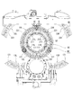
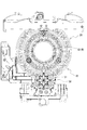
遊技盤90の遊技領域には、表示装置92、始動入賞口931、大入賞口932、アウト口933などが設けられている。表示装置92は、例えば液晶表示装置が用いられ、表示装置92の表示画面(表示部)において特別図柄や普通図柄等が表示される。かかる表示装置92の表示画面は、遊技盤90に形成された開口を通じて視認可能である。なお、図1および図2に示すように、可動演出装置2が所定の演出形態を構成した際には、表示装置92は可動演出装置2の役物に覆われた状態となる。   In the game area of the game board 90, a display device 92, a start winning port 931, a big winning port 932, an out port 933, and the like are provided. As the display device 92, for example, a liquid crystal display device is used, and special symbols, normal symbols, and the like are displayed on the display screen (display unit) of the display device 92. The display screen of the display device 92 is visible through an opening formed in the game board 90. As shown in FIGS. 1 and 2, when the movable effect device 2 configures a predetermined effect form, the display device 92 is covered with the accessory of the movable effect device 2.

また、遊技盤90の遊技領域には、流下する遊技球が衝突することにより遊技球の流下態様に変化を与える障害物としての図示しない遊技釘が複数設けられている。遊技領域を流下する遊技球は、遊技釘に衝突したときの条件に応じて様々な態様に変化する。   The game area of the game board 90 is provided with a plurality of game nails (not shown) as obstacles that change the flow-down mode of the game balls when the flow-down game balls collide with each other. The game ball flowing down the game area changes into various modes depending on the condition when it collides with the game nail.

さらに、表示装置92の周辺には、遊技の装飾効果(演出効果)を高めるための可動演出装置2が設けられている。可動演出装置2は、表示装置92と連動して演出動作を行う。かかる可動演出装置2の構成の詳細については後述する。   Furthermore, a movable effect device 2 is provided around the display device 92 to enhance the decoration effect (effect effect) of the game. The movable effect device 2 performs an effect operation in conjunction with the display device 92. Details of the configuration of the movable effect device 2 will be described later.

なお、図示しないが、遊技機1の背面側には、枠用外部端子基板、表示制御基板、主制御基板、音声制御基板、ランプ制御基板、払出制御基板、発射制御基板、電源基板等の各種基板、カードインターフェース接続部、球寄せ、球タンク、タンクレール、払出装置、発射装置等の各種の遊技機構成部材が設けられている。なお、以下の説明では、主制御基板等の遊技機1の制御を行う構成を一括りに制御手段と称する。   Although not shown, on the back side of the gaming machine 1, there are various types of external terminal board for frame, display control board, main control board, voice control board, lamp control board, payout control board, launch control board, power supply board, etc. Various game machine components, such as a board | substrate, a card interface connection part, a ball holder, a ball tank, a tank rail, a payout apparatus, a launching apparatus, are provided. In the following description, a configuration for controlling the gaming machine 1 such as a main control board is collectively referred to as control means.

このような遊技機1では、発射ハンドル86の操作により、発射装置から遊技領域に遊技球を発射し、遊技領域を流下する遊技球が、始動入賞口931や大入賞口932等の入賞口に入賞すると、所定の数の賞球が払出装置により払い出される。その他、大当たりの抽選方法等は、公知の遊技機の制御方法が適用できるため、説明は省略する。   In such a gaming machine 1, by operating the launch handle 86, a game ball is launched from the launching device to the game area, and the game ball flowing down the game area is used as a prize opening such as the start prize opening 931 and the grand prize winning opening 932. When winning, a predetermined number of prize balls are paid out by the payout device. In addition, since a known game machine control method can be applied to the jackpot lottery method and the like, description thereof is omitted.

(可動演出装置の構成)
以下、遊技機1が備える可動演出装置2の構成について図3〜図26を参照して説明する。可動演出装置2は、遊技機1の制御手段によって制御される遊技演出用の役物(可動部材)である、第一装飾体10および第二装飾体20を有する装飾部材5と、演出体30と、を備える。これらは、遊技盤90の後側に、表示装置92(表示画面)の周囲を囲むように設けられる装置枠体2a(図3参照)に取り付けられ、同一平面上に位置する(これら全てが交差する上下左右方向に広がるある一つの平面が存在する)。以下、各構成について詳細に説明する。
(Configuration of movable production device)
Hereinafter, the configuration of the movable effect device 2 included in the gaming machine 1 will be described with reference to FIGS. The movable effect device 2 includes a decorative member 5 having a first decorative body 10 and a second decorative body 20, which is a game effect accessory (movable member) controlled by the control means of the gaming machine 1, and an effect body 30. And comprising. These are attached to a device frame 2a (see FIG. 3) provided on the rear side of the game board 90 so as to surround the display device 92 (display screen), and are located on the same plane (all of them intersect). There is one plane that spreads in the vertical and horizontal directions). Hereinafter, each configuration will be described in detail.

1)第一装飾体の構成・基本動作
装飾部材5が有する第一装飾体10の構成について説明する。第一装飾体10は、装置枠体2aの下部(表示装置92の表示画面の下側)に取り付けられた役物であり、後述する第二装飾体20とともに遊技状態に応じた装飾を行う部材である。第一装飾体10は、第一装飾体用駆動源14によって第一位置と第二位置の間を移動可能であり、第一要素部材11と、第二要素部材12と、第三要素部材13と、を備える。本実施形態では、各要素部材11,12,13は、遊技機1を上下方向に二分する中央線に関し左右対称に位置する二つの部材から構成される(以下、左側に位置する要素部材を左(第一〜第三)要素部材11L,12L,13L、右側に位置する要素部材を右(第一〜第三)要素部材11R,12R,13Rと区別することもある)。
1) Configuration / Basic Operation of First Decoration Body The configuration of the first decoration body 10 included in the decoration member 5 will be described. The first decorative body 10 is an accessory attached to the lower part of the device frame 2a (the lower side of the display screen of the display device 92), and is a member that performs decoration according to the gaming state together with the second decorative body 20 described later. It is. The first decorative body 10 is movable between a first position and a second position by a first decorative body drive source 14, and includes a first element member 11, a second element member 12, and a third element member 13. And comprising. In the present embodiment, each of the element members 11, 12, and 13 is composed of two members positioned symmetrically with respect to a center line that bisects the gaming machine 1 in the vertical direction (hereinafter, the element member positioned on the left side is the left side). (First to third) element members 11L, 12L, and 13L, and element members located on the right side may be distinguished from right (first to third) element members 11R, 12R, and 13R).

各要素部材11,12,13は、円弧状に形成された環状部111,121,131と、環状部111,121,131の下方に形成される接続部112,912,132を有する。環状部111,121,131は遊技を演出する部分である。この環状部111,121,131の円弧の径が小さい方から順に(曲率が大きい方から順に)第一要素部材11、第二要素部材12、第三要素部材13となる。第一装飾体10における第一要素部材11、第二要素部材12、第三要素部材13の環状部111,121,131の曲率は、それぞれ、後述する第二装飾体20における第一要素部材11、第二要素部材22、第三要素部材23の曲率と略一致する。これら各要素部材11,12,13の環状部111,121,131がならんで遊技者に視認可能となる上方に位置(表示装置92の表示画面の前面側に重なる位置)した状態が、「第一装飾体10が第二位置に位置した状態」である(図11に示した状態)。この第二位置において、各要素部材11,12,13の環状部111,121,131の円弧は同心円状に位置する。また、左要素部材11L,12L,13Lと右要素部材11R,12R,13Rの環状部111,121,131は、同じ径の円弧を描くように一体的な形状を構成する。   Each element member 11, 12, 13 has annular portions 111, 121, 131 formed in an arc shape, and connecting portions 112, 912, 132 formed below the annular portions 111, 121, 131. The annular portions 111, 121, and 131 are portions that produce a game. The first element member 11, the second element member 12, and the third element member 13 are formed in order from the smallest arc diameter of the annular portions 111, 121, and 131 (in descending order of curvature). The curvatures of the annular portions 111, 121, 131 of the first element member 11, the second element member 12, and the third element member 13 in the first decorative body 10 are respectively the first element member 11 in the second decorative body 20 described later. The curvatures of the second element member 22 and the third element member 23 are substantially the same. The state in which the annular portions 111, 121, 131 of these element members 11, 12, 13 are aligned and positioned so as to be visible to the player (position overlapping the front side of the display screen of the display device 92) is “ This is a state in which one decorative body 10 is located at the second position (the state shown in FIG. 11). In this second position, the circular arcs 111, 121, 131 of the element members 11, 12, 13 are located concentrically. The left element members 11L, 12L, and 13L and the annular portions 111, 121, and 131 of the right element members 11R, 12R, and 13R form an integral shape so as to draw an arc having the same diameter.

一方、「第一装飾体10が第一位置に位置した状態」とは、詳細を後述するように、各要素部材11,12,13の環状部111,121,131同士が離れる方向に移動し、表示領域に全ての要素部材11,12,13の環状部111,121,131が重なっていない状態である(図14に示した状態)。第一位置において、第一装飾体10は、装置枠体2aの下部の前側に位置する。   On the other hand, “the state where the first decorative body 10 is located at the first position” means that the annular portions 111, 121, 131 of the element members 11, 12, 13 move away from each other as will be described in detail later. In this state, the annular portions 111, 121, 131 of all the element members 11, 12, 13 do not overlap the display area (the state shown in FIG. 14). In the first position, the first decorative body 10 is located on the lower front side of the device frame 2a.

一方、接続部112,122,132は、環状部111,121,131よりも曲率が大きい円弧状の部分である。第一装飾体10が第二位置に位置する場合において、所定の大きさの円形空間(第一収納部S1)を構成する。この円形空間は、詳細を後述する演出体30が収容可能な大きさである。また、接続部112,122,132の先端(下端)は、略円形に形成されている。各要素部材11,12,13は、接続部112,122,132の略円形部分の中心で装置枠体2aに回転自在に支持されている。平面方向における各要素部材11,12,13の回転中心は同じであり、各接続部112,122,132の円形部分同士は、同一の支持軸16に回転自在に支持されている。この各要素部材11,12,13における接続部112,122,132の円形部分の外周における中央側の一部には、互いに噛合する歯車112a,122a,132aが形成されている。この歯車112a,122a,132aの噛合位置を変化させることによって、要素部材11,12,13が上記略円形部分の中心を回転中心として回転する。すなわち、歯車112a,122a,132aの噛合位置を変化させることによって、第一装飾体10が第一位置から第二位置まで移動する。また、第一左要素部材11L、第二左要素部材12L、第三左要素部材13Lには、下方に向かって突出する被押圧突起112b,122b,132bが形成されている。この各要素部材11,12,13に形成された被押圧突起112b,122b,132bは前後方向に重なるように(平面方向における位置が略同じとなるように)形成されている。この被押圧突起112b,122b,132bは、後述する連繋部材15に形成された押圧突起151b,152b,153bに係合する部分である。   On the other hand, the connecting portions 112, 122, 132 are arc-shaped portions having a larger curvature than the annular portions 111, 121, 131. When the 1st decoration body 10 is located in a 2nd position, the circular space (1st accommodating part S1) of a predetermined | prescribed magnitude | size is comprised. This circular space is large enough to accommodate the effect body 30 described later in detail. Moreover, the front-end | tip (lower end) of the connection parts 112,122,132 is formed in substantially circle shape. Each element member 11, 12, 13 is rotatably supported by the apparatus frame 2 a at the center of the substantially circular portion of the connecting portions 112, 122, 132. The rotation centers of the element members 11, 12, 13 in the plane direction are the same, and the circular portions of the connection portions 112, 122, 132 are rotatably supported by the same support shaft 16. Gears 112 a, 122 a, and 132 a that mesh with each other are formed on a part of the center side of the outer periphery of the circular portions of the connection portions 112, 122, and 132 in the element members 11, 12, and 13. By changing the meshing positions of the gears 112a, 122a, and 132a, the element members 11, 12, and 13 are rotated about the center of the substantially circular portion. That is, the first decorative body 10 moves from the first position to the second position by changing the meshing positions of the gears 112a, 122a, and 132a. The first left element member 11L, the second left element member 12L, and the third left element member 13L are formed with pressed protrusions 112b, 122b, and 132b that protrude downward. The pressed protrusions 112b, 122b, and 132b formed on the element members 11, 12, and 13 are formed so as to overlap in the front-rear direction (the positions in the plane direction are substantially the same). The pressed protrusions 112b, 122b, and 132b are portions that engage with pressing protrusions 151b, 152b, and 153b formed on the connecting member 15 described later.

このような構成の第一装飾体10(各要素部材11,12,13)は、装置枠体2aに固定された第一装飾体用駆動源14と次のように連繋されている。本実施形態では、第一装飾体用駆動源14はモータである。この第一装飾体用駆動源14の出力軸(回転軸)には、出力歯車141が固定されている。一方、装置枠体2aには、幅方向にスライド自在に固定された連繋部材15が設けられている。連繋部材15は、三枚の板状体が前後方向に重なるように組み合わされてなる部材であり、三つの板状体は、それぞれ、第一要素部材11、第二要素部材12、および第三要素部材13に係合する(以下、第一要素部材11に係合する板状体を第一板状体151、第二要素部材12に係合する板状体を第二板状体152、第三要素部材13に係合する板状体を第三板状体153と区別して称することもある)。このうち、少なくともいずれか一つの板状体(本実施形態では第三板状体153)には、ラック15a(歯竿)が形成されており、出力歯車141と噛合している。つまり、出力歯車141が回転することにより、三つの板状体が組み合わされてなる連繋部材15は幅方向にスライドする。   The 1st decoration body 10 (each element member 11, 12, 13) of such a structure is connected with the drive source 14 for the 1st decoration body fixed to the apparatus frame 2a as follows. In the present embodiment, the first decorative body drive source 14 is a motor. An output gear 141 is fixed to the output shaft (rotary shaft) of the first decorative body drive source 14. On the other hand, the device frame 2a is provided with a connecting member 15 that is slidably fixed in the width direction. The connecting member 15 is a member formed by combining three plate-like bodies so as to overlap in the front-rear direction, and the three plate-like bodies are respectively a first element member 11, a second element member 12, and a third element. The plate member that engages with the element member 13 (hereinafter, the plate member that engages with the first element member 11 is the first plate member 151, the plate member that engages with the second element member 12 is the second plate member 152, A plate-like body that engages with the third element member 13 may be referred to as a third plate-like body 153). Among these, at least any one plate-like body (the third plate-like body 153 in the present embodiment) is formed with a rack 15a (tooth ridge) and meshes with the output gear 141. That is, when the output gear 141 rotates, the connecting member 15 formed by combining three plate-like bodies slides in the width direction.

一方、各連繋部材15の板状体151,152,153には、幅方向に長い長孔である貫通孔151a,152a,153aが形成されている。この貫通孔151a,152a,153aには、各接続部112,122,132の円形部分同士を接続し、各要素部材11,12,13を回転自在に支持する支持軸16が挿通されている。そして、各左要素部材11L,12L,13Lの接続部112,122,132に形成された被押圧突起112b,122b,132bは、対応する板状体に形成された貫通孔151a,152a,153aの内側に位置する(被押圧突起112b,122b,132bと貫通孔151a,152a,153aが同一平面上に位置する)。   On the other hand, the plate-like bodies 151, 152, 153 of the connecting members 15 are formed with through holes 151a, 152a, 153a which are long holes in the width direction. A support shaft 16 that connects the circular portions of the connection portions 112, 122, and 132 and rotatably supports the element members 11, 12, and 13 is inserted into the through holes 151a, 152a, and 153a. The pressed projections 112b, 122b, and 132b formed on the connecting portions 112, 122, and 132 of the left element members 11L, 12L, and 13L are formed through the through holes 151a, 152a, and 153a formed in the corresponding plate-like bodies. It is located inside (the pressed projections 112b, 122b, 132b and the through holes 151a, 152a, 153a are located on the same plane).

また、貫通孔151a,152a,153aの下壁の右側には、押圧突起151b,152b,153bが形成されている。この押圧突起151b,152b,153bの存在により、貫通孔151a,152a,153aには上下方向における大きさが相対的に大きい部分(相対的に幅広の部分)と相対的に小さい部分(相対的に幅狭の部分)が形成される。押圧突起151b,152b,153bは、板状体によって幅方向の長さが異なる。具体的には、第一板状体151に形成された押圧突起151bが一番長く、この第一板状体151に形成された押圧突起151bよりも第二板状体152に形成された押圧突起152bは短い。さらに、第二板状体152に形成された押圧突起152bよりも第三板状体153に形成された押圧突起153bは短い。これら三つの板状体は前後方向に重ねられているため、連繋部材15全体として前方から見ると、第一板状体151における押圧突起151bの左端が最も左寄りに位置し、第三板状体153における押圧突起153bの左端が最も右寄りに位置する構造となる。なお、各押圧突起151b,152b,153bの左端は、緩やかに傾斜した傾斜面となっている。   Further, pressing protrusions 151b, 152b, and 153b are formed on the right side of the lower walls of the through holes 151a, 152a, and 153a. Due to the presence of the pressing protrusions 151b, 152b, and 153b, the through holes 151a, 152a, and 153a have a relatively large portion (relatively wide portion) and a relatively small portion (relatively large portion) in the vertical direction. A narrow portion) is formed. The pressing protrusions 151b, 152b, and 153b have different lengths in the width direction depending on the plate-like body. Specifically, the pressing protrusion 151b formed on the first plate-shaped body 151 is the longest, and the pressing formed on the second plate-shaped body 152 is longer than the pressing protrusion 151b formed on the first plate-shaped body 151. The protrusion 152b is short. Further, the pressing protrusion 153 b formed on the third plate-like body 153 is shorter than the pressing protrusion 152 b formed on the second plate-like body 152. Since these three plate-like bodies are overlapped in the front-rear direction, the left end of the pressing protrusion 151b in the first plate-like body 151 is located on the leftmost side when viewed from the front as the whole connecting member 15, and the third plate-like body The left end of the pressing protrusion 153b at 153 is the most right-sided structure. In addition, the left end of each pressing protrusion 151b, 152b, 153b is an inclined surface that is gently inclined.

以上の構成を備える第一装飾体10は、次のように動作する。第一装飾体用駆動源14に固定された出力歯車141が、連繋部材15のラック15aにおける左端部近傍に噛合した状態であるとき、各左要素部材11L,12L,13Lの接続部112,122,132に形成された被押圧突起112b,122b,132bは、各板状体の貫通孔151a,152a,153aにおける相対的に幅広の部分に位置する。つまり、押圧突起151b,152b,153bが形成されていない部分に位置するため、被押圧突起112b,122b,132bは押圧突起151b,152b,153bに接触しない。したがって、各要素部材11,12,13に作用する部材は何も存在しないため、環状部111,121,131の自重によって環状部111,121,131が下方に位置する。具体的には、全ての要素部材11,12,13の環状部111,121,131が表示装置92の表示画面の前面側に重ならない位置、すなわち、第一装飾体10(第一装飾体10を構成する全ての要素部材11,12,13)は第一位置に位置する(図14参照)。   The first decorative body 10 having the above configuration operates as follows. When the output gear 141 fixed to the first decorative body drive source 14 is engaged with the vicinity of the left end of the rack 15a of the connecting member 15, the connecting portions 112, 122 of the left element members 11L, 12L, 13L. , 132 are located at relatively wide portions of the through holes 151a, 152a, 153a of the plate-like bodies. That is, since the pressing protrusions 151b, 152b, and 153b are located at portions where the pressing protrusions 151b, 152b, and 153b are not formed, the pressed protrusions 112b, 122b, and 132b do not contact the pressing protrusions 151b, 152b, and 153b. Accordingly, there is no member that acts on each of the element members 11, 12, and 13, and the annular portions 111, 121, and 131 are positioned below due to the weight of the annular portions 111, 121, and 131. Specifically, the positions where the annular portions 111, 121, 131 of all the element members 11, 12, 13 do not overlap the front side of the display screen of the display device 92, that is, the first decorative body 10 (first decorative body 10 Are all located at the first position (see FIG. 14).

この状態から、第一装飾体用駆動源14を駆動し出力歯車141を一方向に回転させると、連繋部材15が左方向にスライドする。すると、まず、左端が最も左寄りに位置する第一板状体151の押圧突起151bに、第一左要素部材11Lの接続部112に形成された被押圧突起112bが接触する。具体的には、被押圧突起112bが押圧突起151bによって押し上げられる方向に移動する。このように被押圧突起112bが押し上げられると、第一左要素部材11Lは、環状部111が右に移動する方向(時計回り)に回転する。このように第一左要素部材11Lが回転すると、第一左要素部材11Lの歯車112aに噛合する歯車112aを有する第一右要素部材11Rは、環状部111が左に移動する方向(反計回り)に回転する。このように、第一左要素部材11Lと第一右要素部材11Rは、各々の環状部111が互いに近づく方向に回転し、環状部111が表示装置92の表示画面の前面側に重なる位置まで移動する(図13参照)。   From this state, when the first decorative body drive source 14 is driven to rotate the output gear 141 in one direction, the connecting member 15 slides to the left. Then, first, the pressed protrusion 112b formed on the connection portion 112 of the first left element member 11L comes into contact with the pressing protrusion 151b of the first plate-like body 151 whose left end is located on the leftmost side. Specifically, the pressed protrusion 112b moves in a direction in which it is pushed up by the pressing protrusion 151b. When the pressed protrusion 112b is pushed up in this way, the first left element member 11L rotates in the direction in which the annular portion 111 moves to the right (clockwise). When the first left element member 11L rotates in this way, the first right element member 11R having the gear 112a meshing with the gear 112a of the first left element member 11L has a direction in which the annular portion 111 moves to the left (counterclockwise). ). Thus, the first left element member 11L and the first right element member 11R rotate in a direction in which the respective annular portions 111 approach each other, and move to a position where the annular portion 111 overlaps the front side of the display screen of the display device 92. (See FIG. 13).

さらに出力歯車141を一方向に回転させると、第二板状体152の押圧突起152bに、第二左要素部材12Lの接続部122に形成された被押圧突起122bが接触する。これにより、上記第一要素部材11と同様に、第二左要素部材12Lと第二右要素部材12Rは、各々の環状部121が互いに近づく方向に回転し、環状部121が表示装置92の表示画面の前面側に重なる位置まで移動する(図12参照)。そして、さらに出力歯車141を一方向に回転させると、第三板状体153の押圧突起153bに、第三左要素部材13Lの接続部132に形成された被押圧突起132bが接触する。これにより、上記第一要素部材11、第二要素部材12と同様に、第三左要素部材13Lと第三右要素部材13Rは、各々の環状部131が互いに近づく方向に回転し、環状部131が表示装置92の表示画面の前面側に重なる位置まで移動する(図11参照)。   When the output gear 141 is further rotated in one direction, the pressed protrusion 122b formed on the connection portion 122 of the second left element member 12L contacts the pressing protrusion 152b of the second plate-like body 152. Accordingly, like the first element member 11, the second left element member 12 </ b> L and the second right element member 12 </ b> R rotate in a direction in which the respective annular portions 121 approach each other, and the annular portion 121 is displayed on the display device 92. Move to a position overlapping the front side of the screen (see FIG. 12). When the output gear 141 is further rotated in one direction, the pressed protrusion 132b formed on the connecting portion 132 of the third left element member 13L comes into contact with the pressing protrusion 153b of the third plate-like body 153. Thereby, similarly to the said 1st element member 11 and the 2nd element member 12, the 3rd left element member 13L and the 3rd right element member 13R rotate in the direction in which each annular part 131 approaches mutually, and the annular part 131 Moves to a position overlapping the front side of the display screen of the display device 92 (see FIG. 11).

このように、第一装飾体10が第一位置に位置する状態から、出力歯車141を一方向に回転させれば第一要素部材11、第二要素部材12、第三要素部材13、の順で、環状部111,121,131が表示装置92の表示画面の前面側に重なる第二位置まで移動する。具体的には、第一要素部材11が第二位置まで移動し終えてから押圧突起152bに被押圧突起122bが接触することで第二要素部材12の移動が開始され、第二要素部材12が第二位置まで移動し終えてから押圧突起153bに被押圧突起132bが接触することで三要素部材13の移動が開始される。第三要素部材13が第二位置まで移動し終えると、図11に示すような第一装飾体10全体が第二位置に位置した状態となる。このとき、左要素部材11L,12L,13Lと右要素部材11R,12R,13Rの接続部112,122,132同士の間には、所定の大きさの空間(第一収納部S1)が形成される。   Thus, if the output gear 141 is rotated in one direction from the state in which the first decorative body 10 is located at the first position, the first element member 11, the second element member 12, and the third element member 13 in this order. Thus, the annular portions 111, 121, 131 move to the second position overlapping the front side of the display screen of the display device 92. Specifically, after the first element member 11 finishes moving to the second position, the pressed protrusion 122b comes into contact with the pressed protrusion 152b, and the movement of the second element member 12 is started. The movement of the three-element member 13 is started when the pressed protrusion 132b comes into contact with the pressing protrusion 153b after the movement to the second position. When the third element member 13 finishes moving to the second position, the entire first decorative body 10 as shown in FIG. 11 is in the second position. At this time, a space (first storage portion S1) having a predetermined size is formed between the connection portions 112, 122, and 132 of the left element members 11L, 12L, and 13L and the right element members 11R, 12R, and 13R. The

一方、第一装飾体10を第二位置から第一位置に移動させる際には、第一装飾体用駆動源14を駆動し出力歯車141を他方向に回転させ、連繋部材15を右方向にスライドさせる。すると、まず、左端が最も右寄りに位置する第三板状体153の押圧突起153bに、第三左要素部材13Lの接続部132に形成された被押圧突起132bが接触した状態が解消される。具体的には、被押圧突起132bが押圧突起153bによって押し上げられた状態が解消される。このように被押圧突起132bが押し上げられた状態が解消されると、第三左要素部材13Lは、環状部131がその重さにより(重力の作用により)左に移動する方向(反時計回り)に回転する。このように第三左要素部材13Lが回転すると、第三左要素部材13Lの歯車132aに噛合する歯車132aを有する第三右要素部材13Rは、環状部131が右に移動する方向(時計回り)に回転する。このように、第三左要素部材13Lと第三右要素部材13Rは、各々の環状部131が互いに離れる方向に回転し、環状部131が表示装置92の表示画面の前面側に重ならない位置まで移動する(図12参照)。   On the other hand, when the first decorative body 10 is moved from the second position to the first position, the first decorative body drive source 14 is driven, the output gear 141 is rotated in the other direction, and the connecting member 15 is moved rightward. Slide. Then, first, the state in which the pressed protrusion 132b formed in the connection portion 132 of the third left element member 13L is in contact with the pressing protrusion 153b of the third plate-like body 153 whose left end is located closest to the right side. Specifically, the state where the pressed protrusion 132b is pushed up by the pressing protrusion 153b is eliminated. When the pushed-up protrusion 132b is thus lifted, the third left element member 13L is moved in the direction in which the annular portion 131 moves to the left (by the action of gravity) (counterclockwise). Rotate to. When the third left element member 13L rotates in this way, the third right element member 13R having the gear 132a meshing with the gear 132a of the third left element member 13L is in the direction in which the annular portion 131 moves to the right (clockwise). Rotate to. In this way, the third left element member 13L and the third right element member 13R rotate in a direction in which the respective annular portions 131 are separated from each other until the annular portion 131 does not overlap the front side of the display screen of the display device 92. Move (see FIG. 12).

さらに出力歯車141を一方向に回転させると、第二板状体152の押圧突起152bに、第二左要素部材12Lの接続部122に形成された被押圧突起122bが接触した状態が解消される。これにより、上記第三要素部材13と同様に、第二左要素部材12Lと第二右要素部材12Rは、各々の環状部121が互いに離れる方向に回転し、環状部121が表示装置92の表示画面の前面側に重ならない位置まで移動する(図13参照)。そして、さらに出力歯車141を一方向に回転させると、第一板状体151の押圧突起151bに、第一左要素部材11Lの接続部112に形成された被押圧突起112bが接触した状態が解消される。これにより、上記第三要素部材13、第二要素部材12と同様に、第一左要素部材11Lと第一右要素部材11Rは、各々の環状部111が互いに離れる方向に回転し、環状部111が表示装置92の表示画面の前面側に重ならない位置まで移動する(図14参照)。   Further, when the output gear 141 is rotated in one direction, the pressed protrusion 122b formed on the connection portion 122 of the second left element member 12L is brought into contact with the pressing protrusion 152b of the second plate-like body 152. . Accordingly, similarly to the third element member 13, the second left element member 12 </ b> L and the second right element member 12 </ b> R rotate in a direction in which the respective annular portions 121 are separated from each other, and the annular portion 121 is displayed on the display device 92. Move to a position that does not overlap the front side of the screen (see FIG. 13). Further, when the output gear 141 is further rotated in one direction, the state where the pressed protrusion 112b formed on the connecting portion 112 of the first left element member 11L is in contact with the pressing protrusion 151b of the first plate-like body 151 is eliminated. Is done. Thereby, similarly to the said 3rd element member 13 and the 2nd element member 12, the 1st left element member 11L and the 1st right element member 11R rotate in the direction in which each annular part 111 leaves | separates from each other, and the annular part 111 Moves to a position that does not overlap the front side of the display screen of the display device 92 (see FIG. 14).

このように、第一装飾体10が第二位置に位置する状態から、出力歯車141を他方向に回転させれば第三要素部材13、第二要素部材12、第一要素部材11、の順で、環状部111,121,131が表示装置92の表示画面の前面側に重ならない位置まで移動する。具体的には、第三要素部材13が第一位置まで移動し終えてから押圧突起152bと被押圧突起122bとの接触状態が解消されることで第二要素部材12の移動が開始され、第二要素部材12が第一位置まで移動し終えてから押圧突起151bと被押圧突起112bとの接触状態が解消されることで第一要素部材11の移動が開始される。第一要素部材11が第一位置まで移動し終えると、図14に示すような第一装飾体10全体が第一位置に位置した状態となる。
2)第二装飾体の構成・基本動作
装飾部材5が有する第二装飾体20の構成について説明する。第二装飾体20は、装置枠体2aの上部(表示装置92の表示画面の上側)に取り付けられた役物であり、第二装飾体用駆動源24によって第三位置と第四位置の間を移動可能である。この第二装飾体20は、第一要素部材21と、第二要素部材22と、第三要素部材23と、を備える。本実施形態では、各要素部材21,22,23は、遊技機1を上下方向に二分する中央線に関し左右対称に位置する二つの部材から構成される(以下、左側に位置する要素部材を左(第一〜第三)要素部材21L,22L,23L、右側に位置する要素部材を右(第一〜第三)要素部材21R,22R,23Rと区別することもある)。
Thus, if the output gear 141 is rotated in the other direction from the state in which the first decorative body 10 is located at the second position, the third element member 13, the second element member 12, and the first element member 11 are in this order. Thus, the annular portions 111, 121, 131 move to positions where they do not overlap the front side of the display screen of the display device 92. Specifically, the movement of the second element member 12 is started when the contact state between the pressing protrusion 152b and the pressed protrusion 122b is canceled after the third element member 13 has finished moving to the first position, The movement of the first element member 11 is started by eliminating the contact state between the pressing protrusion 151b and the pressed protrusion 112b after the two-element member 12 has moved to the first position. When the first element member 11 finishes moving to the first position, the entire first decorative body 10 as shown in FIG. 14 is located at the first position.
2) Configuration / Basic Operation of Second Decoration Body A configuration of the second decoration body 20 included in the decoration member 5 will be described. The second decorative body 20 is an accessory attached to the upper part of the device frame 2a (upper side of the display screen of the display device 92). The second decorative body drive source 24 causes the second decorative body 20 to be positioned between the third position and the fourth position. Is movable. The second decorative body 20 includes a first element member 21, a second element member 22, and a third element member 23. In the present embodiment, each of the element members 21, 22, and 23 is composed of two members that are positioned symmetrically with respect to the center line that bisects the gaming machine 1 in the vertical direction (hereinafter, the element member that is positioned on the left side is the left side). (First to third) element members 21L, 22L, and 23L, and element members located on the right side may be distinguished from right (first to third) element members 21R, 22R, and 23R).

各要素部材21,22,23は、円弧状に形成された環状部211,221,231と、環状部211,221,231の上方に形成される接続部212,222,232を有する。環状部211,221,231は、遊技を演出する部分である。この環状部211,221,231の円弧の径が小さい方から順に(曲率が大きい方から順に)第一要素部材21、第二要素部材22、第三要素部材23となる。全ての要素部材21,22,23の環状部211,221,231が遊技者に視認可能となる下方に位置(表示装置92の表示画面の前面側に重なる位置)した状態が、「第二装飾体20が第四位置に位置した状態」である(図17に示した状態)。この第四位置において、各要素部材21,22,23の環状部211,221,231の円弧は同心円状に位置する。また、左要素部材21L,22L,23Lと右要素部材21R,22R,23Rの環状部211,221,231は、同じ径の円弧を描くように一体的な形状を構成する。   Each element member 21, 22, 23 has annular portions 211, 221, 231 formed in an arc shape and connection portions 212, 222, 232 formed above the annular portions 211, 221, 231. The annular portions 211, 211, and 231 are portions that produce a game. The first element member 21, the second element member 22, and the third element member 23 are formed in order from the smaller arc diameter of the annular portions 211, 211, and 231 (in order from the larger curvature). The state where the annular portions 211, 221, and 231 of all the element members 21, 22, and 23 are positioned downward (positions that overlap the front side of the display screen of the display device 92) that can be visually recognized by the player is “second decoration. The state where the body 20 is positioned at the fourth position "(the state shown in FIG. 17). In the fourth position, the arcs of the annular portions 211, 221, 231 of the element members 21, 22, 23 are positioned concentrically. The left element members 21L, 22L, and 23L and the annular portions 211, 221, and 231 of the right element members 21R, 22R, and 23R form an integral shape so as to draw an arc having the same diameter.

一方、「第二装飾体20が第三位置に位置した状態」とは、詳細を後述するように、各要素部材21,22,23の環状部211,221,231同士が離れる方向に移動し、表示装置92の表示画面の前面側に全ての要素部材21,22,23の環状部211,221,231が重なっていない状態である(図14に示した状態)。第三位置において、第二装飾体20は、その大部分が装置枠体2aの上部の後側に位置する。   On the other hand, "the state in which the second decorative body 20 is located at the third position" means that the annular portions 211, 221, 231 of the element members 21, 22, 23 move away from each other, as will be described in detail later. In this state, the annular portions 211, 221, 231 of all the element members 21, 22, 23 do not overlap the front side of the display screen of the display device 92 (the state shown in FIG. 14). In the third position, most of the second decorative body 20 is located on the rear side of the upper portion of the device frame 2a.

一方、接続部212,222,232は、先端(上端)が略円形に形成された部分である。各要素部材21,22,23は、接続部212,222,232の略円形部分の中心で装置枠体2aに回転自在に支持されている。平面方向における各要素部材21,22,23の回転中心は同じであり、各接続部212,222,232の円形部分同士は、同一の支持軸26に回転自在に支持されている。この各要素部材21,22,23における接続部212,222,232の円形部分における中央側の一部には、互いに噛合する歯車212a,222a,232aが形成されている。この歯車212a,222a,232aの噛合位置を変化させることによって、要素部材21,22,23が上記略円形部分の中心を回転中心として回転する。すなわち、歯車212a,222a,232aの噛合位置を変化させることによって、第二装飾体20が第三位置から第四位置まで移動する。また、第一右要素部材21R、第二右要素部材22R、第三右要素部材23Rには、上方に向かって突出する被押圧突起212b,222b,232bが形成されている。この各要素部材21,22,23に形成された被押圧突起212b,222b,232bは前後方向に重なるように(平面方向における位置が略同じとなるように)形成されている。この被押圧突起212b,222b,232bは、後述する連繋部材25に形成された押圧突起251b,252b,253bに係合する部分である。   On the other hand, the connecting portions 212, 222, 232 are portions where the tips (upper ends) are formed in a substantially circular shape. Each element member 21, 22, 23 is rotatably supported by the device frame 2 a at the center of the substantially circular portion of the connection portions 212, 222, 232. The rotation centers of the element members 21, 22, and 23 in the planar direction are the same, and the circular portions of the connection portions 212, 222, and 232 are rotatably supported by the same support shaft 26. Gears 212 a, 222 a, and 232 a that mesh with each other are formed on part of the center side of the circular portions of the connecting portions 212, 222, and 232 in the element members 21, 22, and 23. By changing the meshing positions of the gears 212a, 222a, and 232a, the element members 21, 22, and 23 rotate about the center of the substantially circular portion. That is, the second decorative body 20 moves from the third position to the fourth position by changing the meshing positions of the gears 212a, 222a, and 232a. The first right element member 21R, the second right element member 22R, and the third right element member 23R are formed with pressed protrusions 212b, 222b, and 232b that protrude upward. The pressed projections 212b, 222b, and 232b formed on the element members 21, 22, and 23 are formed so as to overlap in the front-rear direction (the positions in the plane direction are substantially the same). The pressed protrusions 212b, 222b, and 232b are portions that engage with pressing protrusions 251b, 252b, and 253b formed on the connecting member 25 described later.

このような構成の第二装飾体20(各要素部材21,22,23)は、装置枠体2aに固定された第二装飾体用駆動源24と次のように連繋されている。本実施形態では、第二装飾体用駆動源24はモータである。この第二装飾体用駆動源24の出力軸(回転軸)には、出力歯車241が固定されている。一方、装置枠体2aには、幅方向にスライド自在に固定された連繋部材25が設けられている。連繋部材25は、三枚の板状体が前後方向に重なるように組み合わされてなる部材であり、三つの板状体は、それぞれ、第一要素部材21、第二要素部材22、および第三要素部材23に係合する(以下、第一要素部材21に係合する板状体を第一板状体251、第二要素部材22に係合する板状体を第二板状体252、第三要素部材23に係合する板状体を第三板状体253と区別して称することもある)。このうち、少なくともいずれか一つの板状体(本実施形態では第三板状体253)には、ラック25a(歯竿)が形成されており、出力歯車241と噛合している。つまり、出力歯車241が回転することにより、三つの板状体が組み合わされてなる連繋部材25は幅方向にスライドする。   The second decorative body 20 (each element member 21, 22, 23) having such a configuration is connected to the second decorative body drive source 24 fixed to the apparatus frame 2a as follows. In the present embodiment, the second decorative body drive source 24 is a motor. An output gear 241 is fixed to the output shaft (rotary shaft) of the second decorative body drive source 24. On the other hand, the device frame 2a is provided with a connecting member 25 that is slidably fixed in the width direction. The connecting member 25 is a member formed by combining three plate-like bodies so as to overlap in the front-rear direction, and the three plate-like bodies are respectively a first element member 21, a second element member 22, and a third element. The plate member that engages with the element member 23 (hereinafter, the plate member that engages with the first element member 21 is the first plate member 251, and the plate member that engages with the second element member 22 is the second plate member 252, A plate-like body that engages with the third element member 23 may be referred to as a third plate-like body 253). Among these, at least any one plate-like body (third plate-like body 253 in the present embodiment) is formed with a rack 25a (toothed tooth) and meshes with the output gear 241. That is, when the output gear 241 rotates, the connecting member 25 formed by combining three plate-like bodies slides in the width direction.

一方、各連繋部材25の板状体には、幅方向に長い長孔である貫通孔251a,252a,253aが形成されている。この貫通孔251a,252a,253aには、各接続部212,222,232の円形部分同士を接続し、各要素部材21,22,23を回転自在に支持する支持軸26が挿通されている。そして、各右要素部材21R,22R,23Rの接続部212,222,232に形成された被押圧突起212b,222b,232bは、対応する板状体に形成された貫通孔251a,252a,253aの内側に位置する(被押圧突起212b,222b,232bと貫通孔251a,252a,253aが同一平面上に位置する)。   On the other hand, through holes 251a, 252a, and 253a, which are long holes in the width direction, are formed in the plate-like body of each linking member 25. A support shaft 26 is inserted through the through holes 251a, 252a, and 253a to connect the circular portions of the connecting portions 212, 222, and 232 and rotatably support the element members 21, 22, and 23. The pressed projections 212b, 222b, and 232b formed on the connection portions 212, 222, and 232 of the right element members 21R, 22R, and 23R are formed through the through holes 251a, 252a, and 253a formed in the corresponding plate-like bodies. It is located inside (the pressed projections 212b, 222b, 232b and the through holes 251a, 252a, 253a are located on the same plane).

また、貫通孔251a,252a,253aの上壁の右側には、押圧突起251b,252b,253bが形成されている。この押圧突起251b,252b,253bの存在により、貫通孔251a,252a,253aには上下方向における大きさが相対的に大きい部分(相対的に幅広の部分)と相対的に小さい部分(相対的に幅狭の部分)が形成される。押圧突起251b,252b,253bは、板状体によって幅方向の長さが異なる。具体的には、第一板状体251に形成された押圧突起251bが一番短く、この第一板状体251に形成された押圧突起251bよりも第二板状体252に形成された押圧突起252bは長い。さらに、第二板状体252に形成された押圧突起252bよりも第三板状体253に形成された押圧突起253bは長い。これら三つの板状体は前後方向に重ねられているため、連繋部材25全体として前方から見ると、第一板状体251における押圧突起251bの左端が最も右寄りに位置し、第三板状体253における押圧突起253bの左端が最も左寄りに位置する構造となる。なお、各押圧突起251b,252b,253bの左端は、緩やかに傾斜した傾斜面となっている。   Further, pressing protrusions 251b, 252b, and 253b are formed on the right side of the upper wall of the through holes 251a, 252a, and 253a. Due to the presence of the pressing protrusions 251b, 252b, 253b, the through holes 251a, 252a, 253a have a relatively large portion (relatively wide portion) and a relatively small portion (relatively large portion) in the vertical direction. A narrow portion) is formed. The pressing protrusions 251b, 252b, and 253b have different lengths in the width direction depending on the plate-like body. Specifically, the pressing protrusion 251b formed on the first plate 251 is the shortest, and the pressing formed on the second plate 252 is shorter than the pressing protrusion 251b formed on the first plate 251. The protrusion 252b is long. Furthermore, the pressing protrusion 253b formed on the third plate-like body 253 is longer than the pressing protrusion 252b formed on the second plate-like body 252. Since these three plate-like bodies are overlapped in the front-rear direction, the left end of the pressing protrusion 251b in the first plate-like body 251 is located on the most right side when viewed from the front as the whole connecting member 25, and the third plate-like body. The left end of the pressing protrusion 253b at 253 is the leftmost position. In addition, the left end of each pressing protrusion 251b, 252b, 253b is an inclined surface that is gently inclined.

以上の構成を備える第二装飾体20は、次のように動作する。第二装飾体用駆動源24に固定された出力歯車241が、連繋部材25のラック25aにおける左端部近傍に噛合した状態であるとき、各右要素部材21R,22R,23Rの接続部212,222,232に形成された被押圧突起212b,222b,232bは、各板状体の貫通孔251a,252a,253aにおける相対的に幅広の部分に位置する。つまり、押圧突起251b,252b,253bが形成されていない部分に位置するため、被押圧突起212b,222b,232bは押圧突起251b,252b,253bに接触しない。したがって、各要素部材21,22,23に作用する部材は何も存在しないため、環状部211,221,231の自重によって環状部211,221,231が下方に位置する。具体的には、全ての要素部材21,22,23の環状部211,221,231が表示装置92の表示画面の前面側に重なる位置、すなわち、第二装飾体20(第二装飾体20を構成する全ての要素部材21,22,23)は第四位置に位置する(図17参照)。   The second decorative body 20 having the above configuration operates as follows. When the output gear 241 fixed to the second decorative body drive source 24 is engaged with the vicinity of the left end of the rack 25a of the connecting member 25, the connecting portions 212, 222 of the right element members 21R, 22R, 23R. , 232, the pressed projections 212b, 222b, 232b are positioned in relatively wide portions of the through holes 251a, 252a, 253a of the respective plate-like bodies. That is, since the pressing protrusions 251b, 252b, and 253b are located at portions where the pressing protrusions 251b, 252b, and 253b are not formed, the pressed protrusions 212b, 222b, and 232b do not contact the pressing protrusions 251b, 252b, and 253b. Accordingly, there is no member that acts on each of the element members 21, 22, 23, and the annular portions 211, 221, 231 are positioned below due to the weight of the annular portions 211, 221, 231. Specifically, the positions where the annular portions 211, 221, 231 of all the element members 21, 22, 23 overlap the front side of the display screen of the display device 92, that is, the second decorative body 20 (the second decorative body 20 All the constituent elements 21, 22, 23) constituting are located at the fourth position (see FIG. 17).

この状態から、第二装飾体用駆動源24を駆動し出力歯車241を一方向に回転させると、連繋部材25が左方向にスライドする。すると、まず、左端が最も左寄りに位置する第三板状体253の押圧突起253bに、第三右要素部材23Rの接続部232に形成された被押圧突起232bが接触する。具体的には、被押圧突起232bが押圧突起253bによって押し下げられる方向に移動する。このように被押圧突起232bが押し下げられると、第三右要素部材23Rは、環状部231が右に移動する方向(反時計回り)に回転する。このように第三右要素部材23Rが回転すると、第三右要素部材23Rの歯車232aに噛合する歯車232aを有する第三左要素部材23Lは、環状部231が左に移動する方向(時計回り)に回転する。このように、第三左要素部材23Lと第三右要素部材23Rは、各々の環状部231が互いに離れる方向に回転し、環状部231が表示装置92の表示画面の前面側に重ならない位置まで移動する(図16参照)。   From this state, when the second decorative body drive source 24 is driven and the output gear 241 is rotated in one direction, the connecting member 25 slides to the left. Then, first, the pressed protrusion 232b formed on the connection portion 232 of the third right element member 23R comes into contact with the pressing protrusion 253b of the third plate-like body 253 whose left end is located closest to the left. Specifically, the pressed protrusion 232b moves in a direction in which it is pushed down by the pressing protrusion 253b. When the pressed protrusion 232b is pushed down in this way, the third right element member 23R rotates in the direction in which the annular portion 231 moves to the right (counterclockwise). When the third right element member 23R rotates in this way, the third left element member 23L having the gear 232a meshing with the gear 232a of the third right element member 23R has a direction in which the annular portion 231 moves to the left (clockwise). Rotate to. In this way, the third left element member 23L and the third right element member 23R rotate in a direction in which the respective annular portions 231 are separated from each other until the annular portion 231 does not overlap the front side of the display screen of the display device 92. Move (see FIG. 16).

さらに出力歯車241を一方向に回転させると、第二板状体252の押圧突起252bに、第二右要素部材22Rの接続部222に形成された被押圧突起222bが接触する。これにより、上記第三要素部材23と同様に、第二左要素部材22Lと第二右要素部材22Rは、各々の環状部221が互いに離れる方向に回転し、環状部221が表示装置92の表示画面の前面側に重ならない位置まで移動する(図15参照)。そして、さらに出力歯車241を一方向に回転させると、第一板状体251の押圧突起251bに、第一右要素部材21Rの接続部212に形成された被押圧突起212bが接触する。これにより、上記第三要素部材23、第二要素部材22と同様に、第一左要素部材21Lと第一右要素部材21Rは、各々の環状部211が互いに離れる方向に回転し、環状部211が表示装置92の表示画面の前面側に重ならない位置まで移動する(図14参照)。   When the output gear 241 is further rotated in one direction, the pressed protrusion 222b formed on the connection portion 222 of the second right element member 22R comes into contact with the pressing protrusion 252b of the second plate-like body 252. Accordingly, similarly to the third element member 23, the second left element member 22L and the second right element member 22R rotate in a direction in which the respective annular portions 221 are separated from each other, and the annular portion 221 is displayed on the display device 92. Move to a position that does not overlap the front side of the screen (see FIG. 15). When the output gear 241 is further rotated in one direction, the pressed protrusion 212b formed on the connecting portion 212 of the first right element member 21R comes into contact with the pressing protrusion 251b of the first plate-like body 251. Thereby, like the said 3rd element member 23 and the 2nd element member 22, the 1st left element member 21L and the 1st right element member 21R rotate in the direction in which each annular part 211 leaves | separates each other, and the annular part 211 Moves to a position that does not overlap the front side of the display screen of the display device 92 (see FIG. 14).

このように、第二装飾体20が第四位置に位置する状態から、出力歯車241を一方向に回転させれば第三要素部材23、第二要素部材22、第一要素部材21、の順で、環状部211,221,231が表示装置92の表示画面の前面側に重ならない第三位置まで移動する。具体的には、第三要素部材23が第三位置まで移動し終えてから押圧突起252bに被押圧突起222bが接触することで第二要素部材22の移動が開始され、第二要素部材22が第三位置まで移動し終えてから押圧突起251bに被押圧突起212bが接触することで第一要素部材21の移動が開始される。第一要素部材21が第三位置まで移動し終えると、図14に示すような第二装飾体20全体が第三位置に位置した状態となる。   As described above, when the output gear 241 is rotated in one direction from the state where the second decorative body 20 is located at the fourth position, the third element member 23, the second element member 22, and the first element member 21 are arranged in this order. Thus, the annular portions 211, 221, and 231 move to a third position that does not overlap the front side of the display screen of the display device 92. Specifically, the movement of the second element member 22 is started when the pressed protrusion 222b comes into contact with the pressing protrusion 252b after the third element member 23 has moved to the third position, and the second element member 22 The movement of the first element member 21 is started when the pressed protrusion 212b comes into contact with the pressing protrusion 251b after the movement to the third position. When the first element member 21 finishes moving to the third position, the entire second decorative body 20 as shown in FIG. 14 is in the third position.

一方、第二装飾体20を第三位置から第四位置に移動させる際には、第二装飾体用駆動源24を駆動し出力歯車241を他方向に回転させ、連繋部材25を右方向にスライドさせる。すると、まず、左端が最も右寄りに位置する第一板状体251の押圧突起251bに、第一右要素部材21Rの接続部212に形成された被押圧突起212bが接触した状態が解消される。具体的には、被押圧突起212bが押圧突起251bによって押し下げられた状態が解消される。このように被押圧突起212bが押し下げられた状態が解消されると、第一右要素部材21Rは、環状部211がその重さにより(重力の作用により)左に移動する方向(時計回り)に回転する。このように第一右要素部材21Rが回転すると、第一右要素部材21Rの歯車212aに噛合する歯車212aを有する第一左要素部材21Lは、環状部211が右に移動する方向(反時計回り)に回転する。このように、第一左要素部材21Lと第一右要素部材21Rは、各々の環状部211が互いに近づく方向に回転し、環状部211が表示装置92の表示画面の前面側に重なる位置まで移動する(図15参照)。   On the other hand, when the second decorative body 20 is moved from the third position to the fourth position, the second decorative body drive source 24 is driven to rotate the output gear 241 in the other direction, and the connecting member 25 is moved to the right. Slide. Then, first, the state in which the pressed protrusion 212b formed on the connection portion 212 of the first right element member 21R is in contact with the pressing protrusion 251b of the first plate-like body 251 whose left end is located closest to the right. Specifically, the state where the pressed protrusion 212b is pushed down by the pressing protrusion 251b is eliminated. When the pressed-down protrusion 212b is thus released, the first right element member 21R moves in the direction in which the annular portion 211 moves to the left (by the action of gravity) (clockwise) due to its weight. Rotate. When the first right element member 21R rotates in this way, the first left element member 21L having the gear 212a meshing with the gear 212a of the first right element member 21R has a direction in which the annular portion 211 moves to the right (counterclockwise). ). Thus, the first left element member 21L and the first right element member 21R rotate in a direction in which the respective annular portions 211 approach each other, and move to a position where the annular portion 211 overlaps the front side of the display screen of the display device 92. (See FIG. 15).

さらに出力歯車241を一方向に回転させると、第二板状体252の押圧突起252bに、第二右要素部材22Rの接続部222に形成された被押圧突起222bが接触した状態が解消される。これにより、上記第一要素部材21と同様に、第二左要素部材22Lと第二右要素部材22Rは、各々の環状部221が互いに近づく方向に回転し、環状部221が表示装置92の表示画面の前面側に重なる位置まで移動する(図16参照)。そして、さらに出力歯車241を一方向に回転させると、第三板状体253の押圧突起253bに、第三右要素部材23Rの接続部232に形成された被押圧突起232bが接触した状態が解消される。これにより、上記第一要素部材21、第二要素部材22と同様に、第三左要素部材23Lと第三右要素部材23Rは、各々の環状部231が互いに近づく方向に回転し、環状部231が表示装置92の表示画面の前面側に重なる位置まで移動する(図17参照)。   When the output gear 241 is further rotated in one direction, the state where the pressed protrusion 222b formed on the connection portion 222 of the second right element member 22R contacts the pressing protrusion 252b of the second plate-like body 252 is eliminated. . Accordingly, like the first element member 21, the second left element member 22 </ b> L and the second right element member 22 </ b> R rotate in a direction in which the respective annular portions 221 approach each other, and the annular portion 221 is displayed on the display device 92. It moves to a position that overlaps the front side of the screen (see FIG. 16). When the output gear 241 is further rotated in one direction, the pressed protrusion 232b formed on the connection portion 232 of the third right element member 23R is brought into contact with the pressing protrusion 253b of the third plate-like body 253. Is done. Thereby, similarly to the said 1st element member 21 and the 2nd element member 22, the 3rd left element member 23L and the 3rd right element member 23R rotate in the direction in which each annular part 231 approaches mutually, and the annular part 231 Moves to a position overlapping the front side of the display screen of the display device 92 (see FIG. 17).

このように、第二装飾体20が第三位置に位置する状態から、出力歯車241を他方向に回転させれば第一要素部材21、第二要素部材22、第三要素部材23、の順で、環状部211,221,231が表示装置92の表示画面の前面側に重なる第四位置)まで移動する。具体的には、第一要素部材21が第四位置まで移動し終えてから押圧突起252bと被押圧突起222bとの接触状態が解消されることで第二要素部材22の移動が開始され、第二要素部材22が第四位置まで移動し終えてから押圧突起253bと被押圧突起232bとの接触状態が解消されることで第三要素部材23の移動が開始される。第三要素部材23が第四位置まで移動し終えると、図17に示すような第二装飾体20全体が第四位置に位置した状態となる。   Thus, if the output gear 241 is rotated in the other direction from the state in which the second decorative body 20 is located at the third position, the first element member 21, the second element member 22, and the third element member 23 in this order. Thus, the annular portions 211, 221, 231 move to the fourth position where they overlap the front side of the display screen of the display device 92. Specifically, the movement of the second element member 22 is started by eliminating the contact state between the pressing protrusion 252b and the pressed protrusion 222b after the first element member 21 has finished moving to the fourth position. The movement of the third element member 23 is started by eliminating the contact state between the pressing protrusion 253b and the pressed protrusion 232b after the two-element member 22 has moved to the fourth position. When the third element member 23 finishes moving to the fourth position, the entire second decorative body 20 as shown in FIG. 17 is located at the fourth position.

3)演出体の構成・基本動作
演出体30の構成について説明する。演出体30は、装置枠体2aの左部(表示装置92の表示画面の左側)において連結部材を介して演出体用駆動源に接続された独立して動作する役物であり、第一演出位置と第二演出位置の間を移動可能である。本実施形態における演出体30は、正面視円形(三次元的に見れば円柱状)の遊技を演出する部分である。この演出体30が表示装置92の表示画面の下側に位置した状態が、「演出体30が第一演出位置に位置した状態」である(図18(a)、図19に示した状態)。また、演出体30が表示装置92の表示画面の前面側略中央に重なって位置した状態が、「演出体30が第二演出位置に位置した状態」である(図18(b)、図20に示した状態)。なお、演出体30の前面には、図示されない駆動手段により回転する星状の演出要素31が設けられている。この演出体30の形状などは例示であり適宜変更可能である。
3) Configuration / Basic Operation of Production Body The configuration of the production body 30 will be described. The effect body 30 is an accessory that operates independently and is connected to the drive source for the effect body via a connecting member in the left part of the device frame 2a (the left side of the display screen of the display device 92). It is possible to move between the position and the second performance position. The effect body 30 in the present embodiment is a part that produces a game in a circular shape when viewed from the front (a cylindrical shape when viewed three-dimensionally). The state in which the effect body 30 is located on the lower side of the display screen of the display device 92 is the “state in which the effect body 30 is located at the first effect position” (the state shown in FIGS. 18A and 19). . Further, the state in which the effect body 30 is positioned so as to overlap the front center of the display screen of the display device 92 is the “state in which the effect body 30 is positioned at the second effect position” (FIG. 18B, FIG. 20). As shown in the figure). A star-shaped effect element 31 that is rotated by a driving means (not shown) is provided on the front surface of the effect body 30. The shape of the effect body 30 is an example and can be changed as appropriate.

図18等に示すように、連結部材は、主軸32、従動軸33、連結アーム34、および補助アーム35を有する。主軸32および従動軸33の先端部に演出体30が固定されている。また、主軸32および従動軸33の基端部は、装置枠体2aの左部に回動自在に支持されている。同様に連結アーム34も、その基端部が装置枠体2aの左部に回動自在に支持されている。この連結アーム34の回動中心軸は、主軸32の回動中心軸と同一であり、連結アーム34と主軸32は一体的に回転する。連結アーム34の先端側には、連結アーム34の長手方向に延びる長孔が形成されている。この長孔には、補助アーム35の先端部が係合されている。この補助アーム35の基端部は図示されない演出体用駆動源に接続されている。演出体用駆動源は、出力軸(回転軸)が偏心位置(モータの中央軸線からずれた位置)に設けられた偏心モータである。   As shown in FIG. 18 and the like, the connecting member has a main shaft 32, a driven shaft 33, a connecting arm 34, and an auxiliary arm 35. The effect body 30 is fixed to the tip ends of the main shaft 32 and the driven shaft 33. Further, the base end portions of the main shaft 32 and the driven shaft 33 are rotatably supported on the left portion of the device frame 2a. Similarly, the base end portion of the connecting arm 34 is also rotatably supported on the left portion of the apparatus frame 2a. The rotation center axis of the connection arm 34 is the same as the rotation center axis of the main shaft 32, and the connection arm 34 and the main shaft 32 rotate integrally. A long hole extending in the longitudinal direction of the connecting arm 34 is formed on the distal end side of the connecting arm 34. The tip of the auxiliary arm 35 is engaged with the long hole. A base end portion of the auxiliary arm 35 is connected to a drive source for a staging body (not shown). The drive source for the director is an eccentric motor in which the output shaft (rotating shaft) is provided at an eccentric position (a position shifted from the central axis of the motor).

以上の構成を備える演出体30は、次のように動作する。図19に示す演出体30が第一演出位置に位置している状態から、演出体用駆動源の出力軸を一方向に回転させると、補助アーム35の先端部が左方向に移動するように回転する。すると、補助アーム35の先端部が係合している連結アーム34も基端部を中心として左方向(反時計回り)に回転する。連結アーム34が左方向に回転すると、それと一体的に回転する主軸32も左方向(反時計回り)に回転する。すなわち、主軸32の先端部が起き上がる方向に回転する。主軸32の先端部には演出体30が固定されているから、主軸32の左方向への回転によって演出体30は表示装置92の表示画面の前面側略中央に重なる位置まで移動する(図20参照)。なお、この主軸32の移動に伴って主軸32とともに演出体30に固定されている従動軸33も左方向(反時計回り)に回転する。このようにして、演出体30が表示装置92の表示画面の前面側略中央に重なる位置、すなわち第二演出位置に位置した状態となる。なお、演出体30が第二演出位置に位置した状態となったとき、従動軸33が図示されないフォトセンサの検出範囲に入り込む。これにより、演出体30が第二演出位置に位置したことが検出される。   The rendering body 30 having the above configuration operates as follows. From the state where the effect body 30 shown in FIG. 19 is located at the first effect position, when the output shaft of the effector drive source is rotated in one direction, the tip of the auxiliary arm 35 moves to the left. Rotate. Then, the connecting arm 34 with which the distal end portion of the auxiliary arm 35 is engaged also rotates leftward (counterclockwise) around the proximal end portion. When the connecting arm 34 rotates in the left direction, the main shaft 32 that rotates integrally therewith also rotates in the left direction (counterclockwise). That is, the tip end portion of the main shaft 32 rotates in the direction in which it rises. Since the effect body 30 is fixed to the front end portion of the main shaft 32, the effect body 30 moves to a position overlapping the approximate center of the front surface of the display screen of the display device 92 by rotating the main shaft 32 in the left direction (FIG. 20). reference). As the main shaft 32 moves, the driven shaft 33 fixed to the effect body 30 together with the main shaft 32 also rotates in the left direction (counterclockwise). In this manner, the effect body 30 is located at the position where it substantially overlaps the front center of the display screen of the display device 92, that is, the second effect position. When the effect body 30 is in the second effect position, the driven shaft 33 enters a detection range of a photo sensor (not shown). Thereby, it is detected that the production body 30 is located at the second production position.

図20に示す第二演出位置に位置した演出体30を第一演出位置に移動させる際には、演出体用駆動源を他方向に回転させる。これにより、補助アーム35の先端部が右方向に移動するように回転する。すると、補助アーム35の先端部が係合している連結アーム34も基端部を中心として右方向(時計回り)に回転する。連結アーム34が右方向に回転すると、それと一体的に回転する主軸32も右方向(時計回り)に回転する。連結アーム34の先端部には演出体30が固定されているから主軸32の右方向への回転によって演出体30は表示装置92の表示画面の下側に位置するまで移動する。なお、この主軸32の移動に伴って主軸32とともに演出体30に固定されている従動軸33も右方向(時計回り)に回転する。このようにして、演出体30が表示装置92の表示画面の下側に位置する状態、すなわち第一演出位置に位置した状態となる(図19参照)。   When the effector 30 located at the second effect position shown in FIG. 20 is moved to the first effect position, the effector drive source is rotated in the other direction. As a result, the tip of the auxiliary arm 35 rotates so as to move in the right direction. Then, the connecting arm 34 with which the distal end portion of the auxiliary arm 35 is engaged also rotates rightward (clockwise) around the base end portion. When the connecting arm 34 rotates in the right direction, the main shaft 32 that rotates integrally therewith also rotates in the right direction (clockwise). Since the effect body 30 is fixed to the distal end portion of the connecting arm 34, the effect body 30 moves to the lower side of the display screen of the display device 92 by the rotation of the main shaft 32 in the right direction. As the main shaft 32 moves, the driven shaft 33 fixed to the effect body 30 together with the main shaft 32 also rotates in the right direction (clockwise). In this way, the effect body 30 is in a state of being positioned on the lower side of the display screen of the display device 92, that is, in a state of being positioned at the first effect position (see FIG. 19).

(第一装飾体および第二装飾体が有する各要素部材の対応した動作)
上記のように、本実施形態における装飾部材5を構成する第一装飾体10および第二装飾体20は、それぞれ、三つの要素部材21,22,23、11,12,13を有する(図4参照)。第一装飾体10の各要素部材は、第二装飾体20の一の要素部材と対応する。具体的には、第一装飾体10の第一要素部材11と第二装飾体20の第一要素部材21が対応し、第一装飾体10の第二要素部材12と第二装飾体20の第二要素部材22が対応し、第一装飾体10の第三要素部材13と第二装飾体20の第三要素部材23が対応する。すなわち、環状部の曲率が略一致するもの同士が対応した関係である。
(Corresponding operation of each element member of the first decorative body and the second decorative body)
As described above, the first decorative body 10 and the second decorative body 20 constituting the decorative member 5 in the present embodiment each have three element members 21, 22, 23, 11, 12, and 13 (FIG. 4). reference). Each element member of the first decorative body 10 corresponds to one element member of the second decorative body 20. Specifically, the first element member 11 of the first decorative body 10 and the first element member 21 of the second decorative body 20 correspond, and the second element member 12 of the first decorative body 10 and the second decorative body 20 The second element member 22 corresponds to the third element member 13 of the first decorative body 10 and the third element member 23 of the second decorative body 20. That is, a relationship in which the curvatures of the annular portions substantially match each other corresponds.

第一装飾体10の各要素部材と、それに対応した第二装飾体20の一の要素部材は、一体的な形態を構成する。すなわち、第二位置に位置する第一装飾体10の第一要素部材11と第四位置に位置する第二装飾体20の第一要素部材21とは一つの円環形状の構造物(以下、単に小円SCと称することもある)を構成する。同様に、第二位置に位置する第一装飾体10の第二要素部材12と第四位置に位置する第二装飾体20の第二要素部材22とが一つの円環形状の構造物(以下、単に中円MCと称することもある)を構成し、第二位置に位置する第一装飾体10の第三要素部材13と第四位置に位置する第二装飾体20の第三要素部材23とが一つの円環形状の構造物(以下、単に大円LCと称することもある)を構成する。   Each element member of the first decorative body 10 and one element member of the second decorative body 20 corresponding thereto constitute an integral form. That is, the first element member 11 of the first decorative body 10 located at the second position and the first element member 21 of the second decorative body 20 located at the fourth position are one annular structure (hereinafter, (It may be simply referred to as a small circle SC). Similarly, the second element member 12 of the first decorative body 10 positioned at the second position and the second element member 22 of the second decorative body 20 positioned at the fourth position are one annular structure (hereinafter, referred to as “ring element”). The third element member 13 of the first decorative body 10 located at the second position and the third element member 23 of the second decorative body 20 located at the fourth position. Constitute a single ring-shaped structure (hereinafter sometimes simply referred to as a great circle LC).

各要素部材が動作する順は、上述した通りである。本実施形態では、第一装飾体10および第二装飾体20の両方において、遊技盤の中央(上記円環形状の構造物を構成する位置)に移動する場合には、第一要素部材11,21、第二要素部材12,22、第三要素部材13,23の順で、遊技盤の中央から離れる方向に移動する場合には、第三要素部材13,23、第二要素部材22,12、第一要素部材11,21の順で移動する。このような順で要素部材を動作させる連繋部材15(25)の板状体に形成された押圧突起151b,152b,153b(251b,252b,253b)の位置は、各要素部材が前の要素部材が移動し終えてから移動を開始するように設定されている。   The order in which each element member operates is as described above. In the present embodiment, in both the first decorative body 10 and the second decorative body 20, when moving to the center of the game board (the position constituting the annular structure), the first element member 11, 21, second element members 12, 22, third element members 13, 23, when moving in a direction away from the center of the game board, the third element members 13, 23, second element members 22, 12 The first element members 11 and 21 are moved in this order. The positions of the pressing protrusions 151b, 152b, and 153b (251b, 252b, and 253b) formed on the plate-like body of the connecting member 15 (25) that operates the element members in this order are as follows. Is set to start moving after it has moved.

このような構成を有するため、本実施形態にかかる遊技機1の制御手段は、小円SCのみを構成した形態(図21参照)、小円SCと中円MCを構成した形態(図22参照)、小円SCと中円MCと大円LCを構成した形態(図23参照)のいずれかを用いた演出を行うことが可能である。   Since it has such a configuration, the control means of the gaming machine 1 according to the present embodiment has a configuration in which only the small circle SC is configured (see FIG. 21), and a configuration in which the small circle SC and the middle circle MC are configured (see FIG. 22). ), It is possible to produce an effect using any one of the forms (see FIG. 23) configured of the small circle SC, the middle circle MC, and the great circle LC.

このように、第二装飾体20と第一装飾体10は円環形状の構造物を構築する合体動作を行う。なお、第一装飾体10および第二装飾体20が有する要素部材の数(三つ)は例示である。第一装飾体10および第二装飾体20が有する要素部材が同数であれば、その数は適宜変更可能である。   In this way, the second decorative body 20 and the first decorative body 10 perform a uniting operation for constructing an annular structure. In addition, the number (three) of the element members which the 1st decoration body 10 and the 2nd decoration body 20 have is an illustration. If the number of element members included in the first decorative body 10 and the second decorative body 20 is the same, the number can be changed as appropriate.

(装飾部材(第一装飾体および第二装飾体)と演出体を組み合わせた(合体、並設させた)演出)
以下、上記構成を備える可動演出装置2の装飾部材5(第一装飾体10および第二装飾体29)と演出体30を組み合わせた演出(動作)について説明する。なお、可動演出装置2の演出は、第一装飾体10、第二装飾体20、および演出体30がそれぞれ単独で動作する演出を行うことが可能である(図11〜図20で示した通り。説明は省略する)。なお、以下の説明では、(第一装飾体10と第二装飾体20を一つの部材として考えた)装飾部材5全体と演出体30を組み合わせた演出を「演出形態」と称し、(装飾部材5を第一装飾体10と第二装飾体20に分けて考えた)第一装飾体10、第二装飾体20、および演出体30の少なくとも二以上を組み合わせた演出を「演出状態」と称する。なお、本実施形態では、組み合わせとは複数の部材(装飾部材5、演出体30等)が合体、並設などすることで一つの装飾形態を表せばよい。
(A combination of decorative members (first decorative body and second decorative body) and a production body (combining and juxtaposed))
Hereinafter, an effect (operation) in which the decorative member 5 (the first decorative body 10 and the second decorative body 29) of the movable effect device 2 having the above-described configuration and the effect body 30 are combined will be described. In addition, the effect of the movable effect device 2 can be an effect in which the first decorative body 10, the second decorative body 20, and the effect body 30 each operate independently (as shown in FIGS. 11 to 20). (Description is omitted). In the following description, an effect in which the decoration member 5 as a whole (the first decorative body 10 and the second decorative body 20 are considered as one member) and the effect body 30 is referred to as an “effect form”, and (decoration member) 5) is divided into the first decorative body 10 and the second decorative body 20), and the effect of combining at least two of the first decorative body 10, the second decorative body 20, and the effector 30 is referred to as an “effect state”. . In the present embodiment, the combination means that a plurality of members (decorative member 5, effect body 30, etc.) are combined and arranged side by side to represent one decoration form.

1−1)装飾部材と演出体による第一演出形態
装飾部材5と演出体30とを組み合わせた第一演出形態について説明する。第一演出形態は、第一演出位置に位置する演出体30と装飾部材5との組み合わせで構成される演出形態である。第一演出形態における装飾部材5の位置は、どのような位置であってもよいが、好ましい位置としては第一装飾位置が挙げられる。装飾部材5が「第一装飾位置」に位置した状態とは、第一装飾体10が第二位置に位置し、第二装飾体20が第四位置に位置した状態である。この場合、第一装飾体10の左要素部材11L,12L,13Lの接続部112,122,132と右要素部材11R,12R,13Rの接続部112,122,132の間には、所定の大きさの円形空間(第一収納部S1)が形成されるため、この円形空間内に第一演出位置にある演出体30が位置する(収容される)。このように、第一演出位置に位置する演出体30と第一装飾位置に位置する装飾部材5によって、図24に示すような演出形態(第一演出形態の一つ)が構成される。
1-1) 1st effect form by decoration member and effect body The 1st effect form which combined the decoration member 5 and the effect body 30 is demonstrated. The first effect form is an effect form constituted by a combination of the effect body 30 and the decorative member 5 located at the first effect position. The position of the decoration member 5 in the first effect form may be any position, but a preferred position is the first decoration position. The state where the decorative member 5 is positioned at the “first decorative position” is a state where the first decorative body 10 is positioned at the second position and the second decorative body 20 is positioned at the fourth position. In this case, there is a predetermined size between the connection parts 112, 122, 132 of the left element members 11L, 12L, 13L of the first decorative body 10 and the connection parts 112, 122, 132 of the right element members 11R, 12R, 13R. Since the circular space (first storage portion S1) is formed, the effect body 30 at the first effect position is located (accommodated) in the circular space. In this way, the effect form (one of the first effect forms) as shown in FIG. 24 is configured by the effect body 30 located at the first effect position and the decoration member 5 located at the first decoration position.

ここで、装飾部材5が第一装飾位置に位置している上記第一演出形態においては、演出体30は第一演出位置と第二演出位置の間を移動することができない。第二位置に位置する装飾体10の左要素部材11L,12L,13Lと右要素部材11R,12R,13Rによって、演出体30の第一演出位置と第二演出位置との間の移動経路が遮られるからである。これに対し、装飾部材5が第二装飾位置に位置している状態(第一装飾体10が第一位置に位置し、第二装飾体20が第三位置に位置している状態)においては、演出体30の第一演出位置と第二演出位置との間の移動経路が遮られた状態にないから、演出体30の第一演出位置と第二演出位置の間の移動が可能である。つまり、第一装飾位置に位置する装飾部材5は、演出体30の第一演出位置と第二演出位置との間の移動を規制する移動規制部を構成する。   Here, in the first effect form in which the decoration member 5 is located at the first decoration position, the effect body 30 cannot move between the first effect position and the second effect position. The movement path between the first effect position and the second effect position of the effect body 30 is blocked by the left element members 11L, 12L, and 13L and the right element members 11R, 12R, and 13R of the decorative body 10 located at the second position. Because it is. On the other hand, in the state where the decorative member 5 is located at the second decorative position (the state where the first decorative body 10 is located at the first position and the second decorative body 20 is located at the third position). Since the movement path between the first effect position and the second effect position of the effector 30 is not blocked, the movement between the first effect position and the second effect position of the effector 30 is possible. . That is, the decoration member 5 located at the first decoration position constitutes a movement restricting unit that restricts movement of the effect body 30 between the first effect position and the second effect position.

また、上記第一演出形態の一つである図24に示した形態では、第一装飾体10における左要素部材11L,12L,13Lの環状部111,121,131と右要素部材11R,12R,13Rの環状部111,121,131、および、第二装飾体20における左要素部材21L,22L,23Lの環状部211,221,231と右要素部材21R,22R,23Rの環状部211,221,231によって所定の大きさの円形空間(第二収納部S2)が形成される。この第二収納部S2内には演出体30が位置していないため、第二収納部S2から装飾部材5の後側に位置する表示装置92の表示部(表示画面の一部)が視認可能である。つまり、かかる形態において、演出体30が位置していない第二収納部S2は、表示装置92の表示部が視認可能な視認窓Wとして機能する。   Moreover, in the form shown in FIG. 24 which is one of the first effects, the annular parts 111, 121, 131 of the left element members 11L, 12L, 13L in the first decorative body 10 and the right element members 11R, 12R, 13R annular portions 111, 121, 131, and annular elements 211, 221, 231, left element members 21L, 22L, 23L of second decorative body 20 and annular portions 211, 221 of right element members 21R, 22R, 23R, A circular space (second storage portion S2) having a predetermined size is formed by 231. Since the effect body 30 is not located in the second storage part S2, the display part (part of the display screen) of the display device 92 located on the rear side of the decorative member 5 from the second storage part S2 is visible. It is. That is, in such a form, the second storage unit S <b> 2 in which the effect body 30 is not located functions as a viewing window W through which the display unit of the display device 92 can be viewed.

1−2)装飾部材と演出体による第二演出形態
装飾部材5と演出体30とを組み合わせた第二演出形態について説明する。第二演出形態は、第二演出位置に位置する演出体30と装飾部材5との組み合わせで構成される演出形態である。第二演出形態における装飾部材5の位置は、どのような位置であってもよいが、好ましい位置としては上記第一装飾位置が挙げられる。この場合、第一装飾体10における左要素部材11L,12L,13Lの環状部111,121,131と右要素部材11R,12R,13Rの環状部111,121,131、および、第二装飾体20における左要素部材21L,22L,23Lの環状部211,221,231と右要素部材21R,22R,23Rの環状部211,221,231によって第二収納部S2が形成されるため、この円形空間内に第二演出位置にある演出体30が位置する(収容される)。このように、第二演出位置に位置する演出体30と第一装飾位置に位置する装飾部材5によって、図25に示すような演出形態(第二演出形態の一つ)が構成される。
1-2) Second effect form by decoration member and effect body A second effect form in which the decoration member 5 and the effect body 30 are combined will be described. The second effect form is an effect form constituted by a combination of the effect body 30 and the decorative member 5 located at the second effect position. The position of the decorative member 5 in the second effect form may be any position, but a preferable position is the first decorative position. In this case, the annular portions 111, 121, 131 of the left element members 11L, 12L, 13L and the annular portions 111, 121, 131 of the right element members 11R, 12R, 13R in the first decorative body 10 and the second decorative body 20 In this circular space, the second storage portion S2 is formed by the annular portions 211, 221, 231 of the left element members 21L, 22L, 23L and the annular portions 211, 221, 231, of the right element members 21R, 22R, 23R. The production body 30 in the second production position is located (accommodated). In this way, the effect form (one of the second effect forms) as shown in FIG. 25 is configured by the effect body 30 located at the second effect position and the decoration member 5 located at the first decoration position.

ここで、上記第二演出形態においても、装飾部材5が第一装飾位置に位置しているから、演出体30は第一演出位置と第二演出位置の間を移動することができない。つまり、第一装飾位置に位置する装飾部材5は、演出体30の第一演出位置と第二演出位置との間の移動を規制する移動規制部を構成する。演出体30を移動させる際には、装飾部材5を第二装飾位置に位置させればよい。   Here, also in the said 2nd production form, since the decoration member 5 is located in the 1st decoration position, the production body 30 cannot move between the 1st production position and the 2nd production position. That is, the decoration member 5 located at the first decoration position constitutes a movement restricting unit that restricts movement of the effect body 30 between the first effect position and the second effect position. What is necessary is just to position the decoration member 5 in a 2nd decoration position when moving the production body 30. FIG.

また、上記第二演出形態の一つである図25に示した形態では、第一装飾体10の左要素部材11L,12L,13Lの接続部112,122,132と右要素部材11R,12R,13Rの接続部112,122,132の間には、第一収納部S1が形成される。この第一収納部S1内には演出体30が位置していないため、第一収納部S1から装飾部材5の後側に位置する表示装置92の表示部(表示画面の一部)が視認可能である。つまり、かかる形態において、演出体30が位置していない第一収納部S2は、表示装置92の表示部が視認可能な視認窓Wとして機能する。   Moreover, in the form shown in FIG. 25 which is one of the second effect forms, the connection parts 112, 122, 132 of the left element members 11L, 12L, 13L of the first decorative body 10 and the right element members 11R, 12R, A first storage portion S1 is formed between the connection portions 112, 122, and 132 of 13R. Since the effect body 30 is not located in the first storage part S1, the display part (part of the display screen) of the display device 92 located on the rear side of the decorative member 5 from the first storage part S1 is visible. It is. That is, in such a form, the first storage unit S2 in which the effect body 30 is not located functions as a visual recognition window W through which the display unit of the display device 92 is visible.

2−1)第一装飾体と演出体による第一演出状態
第一装飾体10と演出体30とを組み合わせた第一演出状態について説明する。第一装飾体10が第二位置に位置する場合、左要素部材11L,12L,13Lの接続部112,122,132と右要素部材11R,12R,13Rの接続部112,122,132の間には、所定の大きさの円形空間(第一収納部S1)が形成される。この円形空間内に第一演出位置にある演出体30が位置する(収容される)ことにより、図26に示す第一演出状態が構成される。このように、第一演出位置に位置する演出体30と第一装飾体10の組み合わせによって第一演出状態が構成される。
2-1) First production state by first decoration body and production body A first production state in which the first decoration body 10 and the production body 30 are combined will be described. When the first decorative body 10 is located at the second position, it is between the connection portions 112, 122, 132 of the left element members 11L, 12L, 13L and the connection portions 112, 122, 132 of the right element members 11R, 12R, 13R. A circular space (first storage part S1) having a predetermined size is formed. When the effect body 30 at the first effect position is located (accommodated) in this circular space, the first effect state shown in FIG. 26 is configured. Thus, the first effect state is configured by the combination of the effector 30 and the first decorative body 10 located at the first effect position.

さらに、第一装飾体10と演出体30とによって構成することのできる別の演出状態として、第二位置にある第一装飾体10と第二演出位置にある演出体30とによって構成される図27に示す演出状態が例示できる。なお、このとき、演出体30が位置していない第一収納部S1は、表示装置92の表示部が視認可能な視認窓Wとして機能する。   Furthermore, the figure comprised by the 1st decoration body 10 in a 2nd position and the production body 30 in a 2nd production position as another production state which can be comprised with the 1st decoration body 10 and the production body 30. FIG. The effect state shown in 27 can be illustrated. At this time, the first storage unit S1 in which the effect body 30 is not located functions as a viewing window W through which the display unit of the display device 92 is visible.

また、このように第一演出状態を構成する第一装飾体10および演出体30には、次のような関係性がある。演出体30が第一演出位置および第二演出位置のいずれに位置する場合であっても、第一装飾体10は第一位置と第二位置の間を自由に移動することができる(演出体30に干渉しない)。一方、第一装飾体10が第二位置に位置する場合には、演出体30が第一演出位置および第二演出位置のいずれに位置する場合であっても、移動することはできない(第一装飾体10が演出体30の第一演出位置と第二演出位置との間の移動を規制する移動規制部を構成する)。これに対し、第一装飾体10が第一位置に位置する場合には、演出体30は第一演出位置と第二演出位置の間を自由に移動することができる(第一位置に位置する第一装飾体10に干渉しない)。   In addition, the first decorative body 10 and the rendering body 30 constituting the first rendering state have the following relationship. The first decorative body 10 can freely move between the first position and the second position regardless of whether the effect body 30 is located at the first effect position or the second effect position (effect object). 30). On the other hand, when the first decorative body 10 is located at the second position, it cannot move regardless of whether the effect body 30 is located at either the first effect position or the second effect position (the first effect position). The decorative body 10 constitutes a movement restricting unit that restricts movement of the effect body 30 between the first effect position and the second effect position). On the other hand, when the first decorative body 10 is located at the first position, the effect body 30 can freely move between the first effect position and the second effect position (positioned at the first position). It does not interfere with the first decorative body 10).

したがって、遊技機1の制御手段は、第一装飾体10と演出体30を次のように制御する。「1.第一装飾体10を第一位置から第二位置に移動させ、かつ、演出体30を第一演出位置から第二演出位置へと移動させようとする際」には、演出体30を第一演出位置から第二演出位置へと移動させてから、第一装飾体10を第一位置から第二位置に移動させる。最初に第一装飾体10を第二位置に移動させてしまうと演出体30が円形空間(第一収納部S1)に収納された状態となり、全く移動することができなくなってしまうからである。「2.第一装飾体10を第一位置から第二位置に移動させ、かつ、演出体30を第一演出位置に位置させたままとする」際には、そのまま第一装飾体10のみを第一位置から第二位置へ移動させればよい。「3.第一装飾体10を第二位置から第一位置に移動させ、かつ、演出体30を第二演出位置から第一演出位置に移動させようとする際」には、第一装飾体10を第二位置から第一位置に移動させてから、演出体30を第二演出位置から第一演出位置に移動させる。第二位置に位置する第一装飾体10によって表示装置92の表示画面の下側に円形空間が形成されているからである。「4.第一装飾体10を第二位置から第一位置に移動させ、かつ、演出体30を第二演出位置に位置させたままとする際」には、そのまま第一装飾体10のみを第二位置から第一位置へ移動させればよい。   Therefore, the control means of the gaming machine 1 controls the first decorative body 10 and the effect body 30 as follows. “1. When the first decorative body 10 is moved from the first position to the second position and the effect body 30 is to be moved from the first effect position to the second effect position”, the effect body 30 Is moved from the first effect position to the second effect position, and then the first decorative body 10 is moved from the first position to the second position. This is because if the first decorative body 10 is first moved to the second position, the effect body 30 is stored in the circular space (first storage portion S1) and cannot be moved at all. When “2. Move the first decorative body 10 from the first position to the second position and keep the rendering body 30 in the first rendering position”, only the first decorative body 10 is left as it is. What is necessary is just to move to a 2nd position from a 1st position. “3. When the first decorative body 10 is moved from the second position to the first position and the effect body 30 is to be moved from the second effect position to the first effect position” After moving 10 from the second position to the first position, the effector 30 is moved from the second effect position to the first effect position. This is because a circular space is formed below the display screen of the display device 92 by the first decorative body 10 located at the second position. “4. When moving the first decorative body 10 from the second position to the first position and keeping the rendering body 30 in the second rendering position”, only the first decorative body 10 is used as it is. What is necessary is just to move to a 1st position from a 2nd position.

なお、演出体30の第一演出位置と第二演出位置との間の移動を規制する移動規制部として、第二装飾体20を用いることもできる。具体的には、第二装飾体20における左要素部材21L,22L,23Lの環状部211,221,231と右要素部材21R,22R,23Rの環状部211,221,231の円弧の長さを大きくする(円弧を下方に延ばす)ことにより、第二装飾体20が第四位置に位置しているときには、演出体30の第一演出位置と第二演出位置との間の移動を第二装飾体20の環状部211,221,231、211,221,231により規制することができる。この場合に演出体30を移動させるときには、第二装飾体20を第三位置に位置させればよい。   In addition, the 2nd decoration body 20 can also be used as a movement control part which controls the movement between the 1st production position and the 2nd production position of the production body 30. FIG. Specifically, the arc lengths of the annular portions 211, 221, 231 of the left element members 21L, 22L, 23L and the annular portions 211, 221, 231 of the right element members 21R, 22R, 23R in the second decorative body 20 are set. By enlarging (extending the arc downward), when the second decorative body 20 is located at the fourth position, the movement of the effect body 30 between the first effect position and the second effect position is changed to the second decoration. It can be regulated by the annular portions 211, 221, 231, 211, 221, 231 of the body 20. In this case, when the effect body 30 is moved, the second decorative body 20 may be positioned at the third position.

2−2)第二装飾体と演出体による第二演出状態
第二装飾体20と演出体30とを組み合わせた第二演出状態について説明する。上述したように、第二装飾体20は第四位置において各要素部材21,22,23の環状部211,221,231が表示装置92の表示画面の前面側に重なるように位置する。このとき、左要素部材21L,22L,23Lの環状部221,221,231と右要素部材21R,22R,23Rの環状部211,221,231は、下方が破断した円環形状の構造物を構築する。この円環形状の構造物の内側の空間(下方が開口した円形空間)には、第二演出位置に位置する演出体30が入り込むことが可能である。つまり、第四位置に位置する第二装飾体20および第二演出位置に位置する演出体30によって、図28に示す第二演出状態が構成される。
2-2) Second effect state by second decorative body and effect body A second effect state in which the second decorative body 20 and the effect body 30 are combined will be described. As described above, the second decorative body 20 is positioned so that the annular portions 211, 221, 231 of the element members 21, 22, 23 overlap the front side of the display screen of the display device 92 in the fourth position. At this time, the annular portions 221, 221, 231 of the left element members 21L, 22L, and 23L and the annular portions 211, 221, and 231 of the right element members 21R, 22R, and 23R construct a ring-shaped structure whose bottom is broken. To do. The rendering body 30 located at the second rendering position can enter the space inside the annular structure (a circular space having an opening at the bottom). That is, the second effect state shown in FIG. 28 is configured by the second decorative body 20 located at the fourth position and the effect body 30 located at the second effect position.

上記演出体30および第二装飾体20は、一方がどの位置に位置していても、他方が自由に移動することが可能である。詳しくは、演出体30は装置枠体2aで囲まれた領域の上下方向における略中央から下の領域で移動するのに対し、第二装飾体20は装置枠体2aで囲まれた領域の上下方向における略中央から上の領域で移動するから、両者は干渉せず、自由に移動することが可能である。ただし、上述したように、第二装飾体20における左要素部材21L,22L,23Lの環状部211,221,231と右要素部材21R,22R,23Rの環状部211,221,231の円弧の長さを大きくする(円弧を下方に延ばす)ことにより、第二装飾体20を演出体30の移動を規制する移動規制部として機能させることも可能である。   The production body 30 and the second decorative body 20 can move freely regardless of the position where one is located. Specifically, the effect body 30 moves in a region below from the approximate center in the vertical direction of the region surrounded by the device frame 2a, while the second decorative body 20 moves above and below the region surrounded by the device frame 2a. Since they move in the upper region from the approximate center in the direction, they can move freely without interference. However, as described above, the arc lengths of the annular portions 211, 221, 231 of the left element members 21L, 22L, 23L and the annular portions 211, 221, 231 of the right element members 21R, 22R, 23R in the second decorative body 20 By increasing the length (extending the arc downward), it is possible to cause the second decorative body 20 to function as a movement restricting portion that restricts the movement of the effect body 30.

2−3)第一装飾体と第二装飾体による第三演出状態
第一装飾体10と第二装飾体20を組み合わせた第三演出状態について説明する。上述したように、第一装飾体10は第二位置において各要素部材11,12,13の環状部111,121,131が表示装置92の表示画面の前面側に重なるように位置する。このとき、左要素部材11L,12L,13Lの環状部111,121,131と右要素部材11R,12R,13Rの環状部111,121,131は、上方が破断した円環形状の構造物を構築する。一方、第二装飾体20は第四位置において各要素部材21,22,23の環状部211,221,231が表示装置92の表示画面の前面側に重なるように位置し、左要素部材21L,22L,23Lの環状部211,221,231と右要素部材21R,22R,23Rの環状部211,221,231が下方が破断した円環形状の構造物を構築する。第一装飾体10が構築する円環形状の構造物の破断した部分には、第二装飾体20が構築する円環形状の構造物が位置する。つまり、第二位置に位置する第一装飾体10の環状部111,121,131と第四位置に位置する第二装飾体20の環状部211,221,231によって、図21から図23で示したような連続する(破断した部分の無い)円環形状の構造物が構成される。
2-3) Third effect state by first decorative body and second decorative body A third effect state in which the first decorative body 10 and the second decorative body 20 are combined will be described. As described above, the first decorative body 10 is positioned such that the annular portions 111, 121, 131 of the element members 11, 12, 13 overlap the front side of the display screen of the display device 92 at the second position. At this time, the annular portions 111, 121, and 131 of the left element members 11L, 12L, and 13L and the annular portions 111, 121, and 131 of the right element members 11R, 12R, and 13R construct an annular structure that is broken upward. To do. On the other hand, the second decorative body 20 is positioned such that the annular portions 211, 221, 231 of the element members 21, 22, 23 overlap the front side of the display screen of the display device 92 at the fourth position, and the left element member 21L, The annular portions 211, 221, and 231 of 22L and 23L and the annular portions 211, 221, and 231 of the right element members 21R, 22R, and 23R form an annular structure in which the lower part is broken. The ring-shaped structure constructed by the second decorative body 20 is located at a broken portion of the ring-shaped structure constructed by the first decorative body 10. That is, the annular portions 111, 121, 131 of the first decorative body 10 located at the second position and the annular portions 211, 211, 231 of the second decorative body 20 located at the fourth position are shown in FIGS. Such a continuous ring-shaped structure (without a broken portion) is formed.

上記第一装飾体10および第二装飾体20は、一方がどの位置に位置していても、他方が自由に移動することが可能である。詳しくは、第一装飾体10は装置枠体2aで囲まれた領域の上下方向における略中央から下の領域で移動するのに対し、第二装飾体20は装置枠体2aで囲まれた領域の上下方向における略中央から上の領域で移動するから、両者は干渉せず、自由に移動することが可能である。   The first decorative body 10 and the second decorative body 20 can move freely regardless of where one is located. Specifically, the first decorative body 10 moves in a region below the center in the vertical direction of the region surrounded by the device frame 2a, whereas the second decorative body 20 is a region surrounded by the device frame 2a. Since they move in the upper region from the approximate center in the vertical direction, they do not interfere with each other and can move freely.

この第一装飾体10と第二装飾体20によってこの円環形状の構造物を構成する際、演出体30は第一演出位置および第二演出位置のいずれに位置していてもよい。具体的には、第一装飾体10によって構成される上記第一収納部S1に第一演出位置にある演出体30が位置する場合、図24に示す演出状態(上記第一演出形態の一つ)が構成される。また、円環形状の構造物の内側に形成される円形空間(第二収納部S2)に第二演出位置にある演出体30が位置する場合、図25に示す演出状態(上記第二演出形態の一つ)が構成される。このように、第三演出状態は、第一装飾体10と第二装飾体20によって円環形状の構造物が構成される演出状態であるが、別の見方をすれば、第一装飾体10、第二装飾体20、および演出体30によって構成される演出状態(上記第一演出形態や第二演出形態に含まれる演出形態)とも捉えられる。   When the ring-shaped structure is configured by the first decorative body 10 and the second decorative body 20, the effect body 30 may be located at either the first effect position or the second effect position. Specifically, when the effect body 30 at the first effect position is located in the first storage portion S1 configured by the first decorative body 10, the effect state shown in FIG. ) Is configured. Further, when the effect body 30 at the second effect position is located in the circular space (second storage part S2) formed inside the annular structure, the effect state (the second effect form described above) shown in FIG. One). As described above, the third performance state is a production state in which an annular structure is configured by the first decorative body 10 and the second decorative body 20, but if viewed from another perspective, the first decorative body 10 Also, it can be regarded as an effect state (effect form included in the first effect form and the second effect form) constituted by the second decorative body 20 and the effect body 30.

また、上記第三演出状態において、第一収納部S1や第二収納部S2に演出体30が位置していない場合、これら第一収納部S1および第二収納部S2から装飾部材5(第一装飾体10および第二装飾体20)の後側に位置する表示装置92の表示部(表示画面の一部)が視認可能である。つまり、演出体30が位置していない収納部は、表示装置の表示部が視認可能な視認窓Wとして機能する。   Moreover, in the said 3rd production state, when the production body 30 is not located in 1st storage part S1 or 2nd storage part S2, the decoration member 5 (1st from these 1st storage part S1 and 2nd storage part S2). The display part (part of the display screen) of the display device 92 located on the rear side of the decorative body 10 and the second decorative body 20) is visible. That is, the storage unit in which the effect body 30 is not located functions as a viewing window W that can be viewed by the display unit of the display device.

なお、上記第一演出形態と第二演出形態、および、第一演出状態から第三演出状態の説明において、第二装飾体20を第四位置に位置させると説明したケースでは、第二装飾体20の第一要素部材21のみを第四位置に位置させてもよいし、第一要素部材21と第二要素部材22を第四位置に位置させてもよいし、第一要素部材21から第三要素部材23の全てを第四位置に位置させてもよい。同様に、第一装飾体10を第二位置に位置させると説明したケースでは、第一装飾体10の第一要素部材11のみを第二位置に位置させてもよいし、第一要素部材11と第二要素部材12を第二位置に位置させてもよいし、第一要素部材11から第三要素部材13の全てを第二位置に位置させてもよい。   In the description of the first effect form, the second effect form, and the first effect state to the third effect state, in the case where the second decorative body 20 is positioned at the fourth position, the second decorative body is used. Only the 20 first element members 21 may be positioned in the fourth position, the first element member 21 and the second element member 22 may be positioned in the fourth position, All of the three element members 23 may be positioned at the fourth position. Similarly, in the case where the first decorative body 10 is described as being positioned at the second position, only the first element member 11 of the first decorative body 10 may be positioned at the second position, or the first element member 11 may be positioned. The second element member 12 may be positioned at the second position, or all of the first element member 11 to the third element member 13 may be positioned at the second position.

(本実施形態の主な作用効果)
以上説明した本発明にかかる遊技機1によれば、次のような作用効果が奏される。
(Main effects of this embodiment)
According to the gaming machine 1 according to the present invention described above, the following operational effects are achieved.

本実施形態にかかる遊技機1において、第一装飾位置と第二装飾位置との間を移動可能である装飾部材5は、第一演出位置に位置する演出体30と第一演出形態を構成すると共に、第二演出位置に位置する演出体30と第二演出形態を構成する。つまり、独立して動作する演出体30が第一演出位置にあるか第二演出位置にあるかにより別の演出形態を構成することが可能であるから、幅広い演出効果を発現する遊技機1となる。   In the gaming machine 1 according to the present embodiment, the decoration member 5 that is movable between the first decoration position and the second decoration position constitutes the first effect form with the effect body 30 located at the first effect position. At the same time, the effect body 30 located at the second effect position and the second effect form are configured. That is, since it is possible to configure another production form depending on whether the production body 30 that operates independently is in the first production position or the second production position, the gaming machine 1 that exhibits a wide variety of production effects and Become.

また、装飾部材5によって形成される第一収納部S1および第二収納部S2に演出体30が入り込んだ状態とすることができるため、限られた遊技領域を有効に活用して効果的な演出を行うことが可能となる。具体的には、装飾部材5と演出体30との合体動作による優れた演出効果が発現される。   In addition, since the effect body 30 can enter the first storage portion S1 and the second storage portion S2 formed by the decorative member 5, it is possible to effectively utilize the limited game area and effectively produce the effect. Can be performed. Specifically, an excellent performance effect by the combined operation of the decorative member 5 and the performance body 30 is expressed.

また、第一装飾位置に位置している装飾部材5によって、第一演出位置と第二演出位置の間の演出体30の移動を規制する移動規制部が構成されるため(装飾部材5と演出体30の動作が規制されるため)、装飾部材5と演出体30が干渉することを防止しつつ、種々の演出を行うことが可能となる。   In addition, since the decoration member 5 located at the first decoration position constitutes a movement restricting unit that restricts the movement of the effect body 30 between the first effect position and the second effect position (the decoration member 5 and the effect). Since the operation of the body 30 is restricted), various effects can be performed while preventing the decorative member 5 and the effect body 30 from interfering with each other.

また、遊技者は、演出体30が位置していない収容部(視認窓W)から表示装置92の表示部の画像を視認することができる。この表示装置92の表示部における視認窓Wから視認できる部分に種々の画像を映し出すことにより、装飾部材5と表示装置92が一体となった種々の演出を行うことが可能となる。   Further, the player can visually recognize the image on the display unit of the display device 92 from the housing unit (viewing window W) where the effect body 30 is not located. By displaying various images on the display portion of the display device 92 that is visible from the viewing window W, various effects in which the decorative member 5 and the display device 92 are integrated can be performed.

一方、本実施形態にかかる遊技機1において、第一装飾体10は、第一演出位置に位置する演出体30と第一演出状態を構成し、第一装飾体10とともに合体動作を行う第二装飾体20は、第二演出位置に位置する演出体30と第二演出状態を構成する。つまり、独立して動作する演出体30が第一演出位置にあるか第二演出位置にあるかによって、合体動作を行う第一装飾体10および第二装飾体20との組み合わせによって異なる演出状態を構成することが可能であるから、幅広い演出効果を発現する遊技機1となる。   On the other hand, in the gaming machine 1 according to the present embodiment, the first decorative body 10 constitutes the first effect state with the effect body 30 located at the first effect position, and the second decoration body 10 performs a combined operation with the first ornament body 10. The decorative body 20 constitutes the second effect state with the effector 30 located at the second effect position. In other words, depending on whether the effect body 30 that operates independently is in the first effect position or the second effect position, the effect state varies depending on the combination of the first decorative body 10 and the second decorative body 20 that perform the combined operation. Since it can be configured, the gaming machine 1 exhibits a wide range of effects.

また、第一装飾体10は第一位置と第二位置の間を移動可能であり、第二位置に位置する第一装飾体10と第四位置に位置する第二装飾体20によって第三演出状態を構成することができるため、第一装飾体10と第二装飾体20によってより幅広い演出効果を発現することが可能となる。   Further, the first decorative body 10 is movable between the first position and the second position, and the third effect is provided by the first decorative body 10 located at the second position and the second decorative body 20 located at the fourth position. Since the state can be configured, a wider range of effects can be expressed by the first decorative body 10 and the second decorative body 20.

また、第一装飾体10によって第一演出位置に位置する演出体30を収容することができる第一収納部S1、第一装飾体10および第二装飾体20によって第二演出位置に位置する演出体30を収容することができる第二収納部S2が構成される構造であるから、限られた遊技領域を有効に活用して効果的な演出を行うことが可能となる。具体的には、第一装飾体10および第二装飾体20の少なくともいずれか一方と、演出体30との合体動作による優れた演出効果が発現される。   In addition, the first decorative unit 10 can accommodate the effector 30 located at the first effect position, and the first storage part S1, the first ornamental body 10, and the second ornamental body 20 can accommodate the effector 30 positioned at the first effect position. Since the second storage unit S2 that can store the body 30 is configured, it is possible to effectively utilize the limited game area and perform an effective presentation. Specifically, an excellent performance effect by the combined operation of at least one of the first decorative body 10 and the second decorative body 20 and the rendering body 30 is exhibited.

また、遊技機1が備える制御手段により、第一装飾体10と演出体30の干渉を防止しつつ種々の演出を行うことが可能である。   Further, various effects can be performed while preventing interference between the first decorative body 10 and the effect body 30 by the control means provided in the gaming machine 1.

また、第一装飾体10および第二装飾体20が、ともに、複数の要素部材(第一要素部材21,11〜第三要素部材23,13)から構成され、第二装飾体20の要素部材21,22,23と第一装飾体10の要素部材11,12,13が組み合わされて一体的な形態(円環形状の構造物)を構成する構造であるから、第二装飾体20と第一装飾体10によってなされる合体動作に様々な変化をもたらすことができる。換言すれば、複数種類の合体動作による演出を提供することが可能となる。   The first decorative body 10 and the second decorative body 20 are both composed of a plurality of element members (first element members 21, 11 to third element members 23, 13). Since 21, 22, 23 and the element members 11, 12, 13 of the first decorative body 10 are combined to form an integral form (annular structure), the second decorative body 20 and the first decorative body 20 Various changes can be brought about in the merging operation performed by one decorative body 10. In other words, it is possible to provide effects by a plurality of types of coalescing operations.

また、第一装飾体10または第二装飾体20を構成するある要素部材が第一位置または第三位置から第二位置または第四位置に移動し終えてから次の要素部材の第一位置または第三位置から第二位置または第四位置までの移動が行われるように構成されるため、一の要素部材のみで形態を構成したり、複数の要素部材で形態を構成したりすることが可能となり、幅広い演出を提供することが可能となる。   Further, after a certain element member constituting the first decorative body 10 or the second decorative body 20 has moved from the first position or the third position to the second position or the fourth position, the first position of the next element member or Since it is configured to move from the third position to the second position or the fourth position, it is possible to configure the form with only one element member, or to configure the form with multiple element members It becomes possible to provide a wide range of effects.

また、第一装飾体10および第二装飾体20を構成する複数の要素部材(第一要素部材11,21〜第三要素部材13,23)が、予め定められた移動順通りに移動し、同じ移動順の要素部材同士が一体的な形態を構成するから、ある一つの要素部材同士だけで一体的な形態を構成したり、複数の要素部材同士で一体的な形態を構成したりするなど、幅広い演出を提供することができる。   Further, the plurality of element members (first element members 11, 21 to third element members 13, 23) constituting the first decorative body 10 and the second decorative body 20 move in a predetermined movement order, Since the element members in the same movement order form an integral form, an integral form is formed by only one element member, or an integral form is formed by a plurality of element members. , Can provide a wide range of production.

以上、本発明の実施の形態について詳細に説明したが、本発明は上記実施の形態に何ら限定されるものではなく、本発明の要旨を逸脱しない範囲で種々の改変が可能である。   Although the embodiments of the present invention have been described in detail above, the present invention is not limited to the above-described embodiments, and various modifications can be made without departing from the gist of the present invention.

例えば、上記実施形態における、第一装飾体10、第二装飾体20、および演出体30の駆動方法は一例である。上記と同様の動作を行うことができる構成であれば、これら可動部材の駆動方法は適宜変更可能である。   For example, the driving method of the first decorative body 10, the second decorative body 20, and the effect body 30 in the above embodiment is an example. If it is the structure which can perform the operation | movement similar to the above, the drive method of these movable members can be changed suitably.

また、上記実施形態では、第一装飾体10と第二装飾体20の両方において、複数の要素部材が予め定められた動作順で動作することを説明したが、第一装飾体10および第二装飾体20のいずれか一方のみが予め定められた動作順で動作するようにしてもよい。   Moreover, although the said embodiment demonstrated that a several element member operate | moves in the predetermined operation | movement order in both the 1st decorative body 10 and the 2nd decorative body 20, the 1st decorative body 10 and the 2nd Only one of the decorative bodies 20 may be operated in a predetermined operation order.

また、収納部S1,S2の大きさは、演出体30よりも大きければよく、収納部S1,S2に演出体30を収納した際に装飾部材5と演出体30が一体的に見えていれば、演出体30と装飾部材5との間に隙間が生じる構成であってもよいし、演出体30と装飾部材5が接触している構成であってもよい。さらに本実施形態では、装飾部材5および演出体30は少なくとも一部が同一平面上に位置する構成であればよく、全てが同一平面上に位置していなくともよい。   Moreover, the size of storage part S1, S2 should just be larger than the production | presentation body 30, and if the decoration member 5 and the production | presentation body 30 are seen integrally, when the production body 30 is accommodated in storage part S1, S2. The structure in which a gap is generated between the effect body 30 and the decoration member 5 may be used, or the structure in which the effect body 30 and the decoration member 5 are in contact with each other. Furthermore, in this embodiment, the decoration member 5 and the effect body 30 should just be a structure located at least partially on the same plane, and all do not need to be located on the same plane.

1 遊技機
5 装飾部材
10 第一装飾体
11(11L,11R) 第一要素部材
12(12L,12R) 第二要素部材
13(13L,13R) 第三要素部材
20 第二装飾体
21(21L,21R) 第一要素部材
22(22L,22R) 第二要素部材
23(23L,23R) 第三要素部材
S1 第一収納部
S2 第二収納部
W 視認窓
30 演出体
1 gaming machine 5 decorative member 10 first decorative body 11 (11L, 11R) first element member 12 (12L, 12R) second element member 13 (13L, 13R) third element member 20 second decorative body 21 (21L, 21R) First element member 22 (22L, 22R) Second element member 23 (23L, 23R) Third element member S1 First storage part S2 Second storage part W Viewing window 30 Production body

Claims (8)

遊技状態に応じた装飾を行う第一装飾体及び第二装飾体と、
遊技領域に遊技者にとって視認可能に配置され、第一演出位置と第二演出位置との間を移動可能な演出体と、を備え、
前記第一装飾体は前記第一演出位置や前記第二演出位置とは異なる第一位置と第二位置との間を移動可能であり、
前記第二装飾体は前記第一演出位置や前記第二演出位置とは異なる第三位置と第四位置との間を移動可能であり、
前記第一演出位置に位置する前記演出体と前記第二位置に位置する前記第一装飾体との組み合わせで第一演出状態が構成され、
前記第二演出位置に位置する前記演出体と前記第四位置に位置する前記第二装飾体との組み合わせで前記第一演出状態と異なる第二演出状態が構成され、
前記第一装飾体が前記第一位置から前記第二位置に移動することで、前記第一装飾体によって前記第一演出位置に位置する前記演出体の少なくとも一部を収納可能な第一収納部を形成する一方、
前記第二装飾体が前記第三位置から前記第四位置に移動すると共に前記第一装飾体が前記第一位置から前記第二位置に移動することで、前記第二装飾体と前記第一装飾体によって前記第二演出位置に位置する前記演出体の少なくとも一部を収納可能な第二収納部を形成することを特徴とする遊技機。
A first decorative body and a second decorative body that perform decoration according to the gaming state;
The game area is arranged so as to be visible to the player, and is capable of moving between the first effect position and the second effect position,
The first decorative body is movable between a first position and a second position different from the first effect position and the second effect position,
The second decorative body is movable between a third position and a fourth position different from the first effect position and the second effect position,
A first effect state is constituted by a combination of the effect body located at the first effect position and the first decorative body located at the second position,
A second production state different from the first production state is configured by a combination of the production body located at the second production position and the second decorative body located at the fourth position,
A first storage part capable of storing at least a part of the effect body located at the first effect position by the first ornament as the first ornament moves from the first position to the second position. While forming
The second decorative body moves from the third position to the fourth position and the first decorative body moves from the first position to the second position, whereby the second decorative body and the first decorative body are moved. A gaming machine, characterized in that a second storage part capable of storing at least a part of the effect body located at the second effect position is formed by a body .
前記第二位置に位置する前記第一装飾体と前記第四位置に位置する前記第二装飾体との組み合わせで第三演出状態が構成されることを特徴とする請求項1に記載の遊技機。   The gaming machine according to claim 1, wherein a third effect state is configured by a combination of the first decorative body located at the second position and the second decorative body located at the fourth position. . 前記第一装飾体が前記第一位置に位置すると共に前記第二装飾体が前記第三位置に位置している状態においては、前記第一演出位置と前記第二演出位置の間の前記演出体の移動が可能である一方、
前記第一装飾体が前記第二位置に位置するか、または、前記第二装飾体が前記第四位置に位置することで、前記第一演出位置と前記第二演出位置の間の前記演出体の移動を規制する移動規制部が構成されることを特徴とする請求項または請求項のいずれか一項に記載の遊技機。
In the state where the first decorative body is located at the first position and the second decorative body is located at the third position, the effect body between the first effect position and the second effect position. Is possible, while
The first decoration body is located at the second position, or the second decoration body is located at the fourth position, so that the presentation body between the first presentation position and the second presentation position. the gaming machine according to any one of claims 1 or claim 2 movement restricting portion for restricting the movement of is characterized in that it is configured.
前記第一装飾体を前記第一位置から前記第二位置へ移動させようとする際に、前記演出体が前記第一演出位置に位置するときには、前記演出体を前記第一演出位置から前記第二演出位置へと移動させてから前記第一装飾体を前記第一位置から前記第二位置へ移動させるか、または、前記演出体を前記第一演出位置に位置させたまま前記第一装飾体のみを前記第一位置から前記第二位置へ移動させ、
前記第一装飾体を前記第二位置から前記第一位置へ移動させようとする際に、前記演出体が前記第二演出位置に位置するときには、前記第一装飾体を前記第二位置から前記第一位置へと移動させてから前記演出体を前記第二演出位置から前記第一演出位置へ移動させるか、または、前記演出体を前記第二演出位置に位置させたまま前記第一装飾体のみを前記第二位置から前記第一位置へ移動させるように制御する制御手段を備えることを特徴とする請求項に記載の遊技機。
When trying to move the first decorative body from the first position to the second position, when the effect body is located at the first effect position, the effect body is moved from the first effect position to the second position. The first decorative body is moved from the first position to the second position after being moved to the second performance position, or the first decorative body is left in the first performance position. Only from the first position to the second position,
When trying to move the first decorative body from the second position to the first position, when the rendering body is located at the second rendering position, the first decorative body is moved from the second position to the first position. The effector is moved from the second effect position to the first effect position after being moved to the first position, or the effector is kept in the second effect position while the first decorative body is moved. 4. The gaming machine according to claim 3 , further comprising a control means for controlling only the second position from the second position to the first position.
前記第一装飾体は、同一の駆動源で動作する複数の要素部材から構成されるとともに、前記第二装飾体は、同一の駆動源で動作する前記第一装飾体を構成する要素部材と同数の要素部材から構成され、
前記第一装飾体を構成する各要素部材は、予め定められた対応する前記第二装飾体を構成する一の要素部材と一体的な状態を構成することを特徴とする請求項から請求項のいずれか一項に記載の遊技機。
The first decorative body is composed of a plurality of element members that operate with the same drive source, and the second decorative body has the same number as the element members that constitute the first decorative body that operates with the same drive source. Composed of the elements of
Each element member which comprises said 1st decoration body comprises the state integrated with one element member which comprises said predetermined 2nd decoration body corresponding, The Claim 1 to Claim 2 characterized by the above-mentioned. 5. The gaming machine according to any one of 4 .
前記第一装飾体を構成する各要素部材は、前記第一装飾体が第一位置から第二位置に移動しようとする際には、予め定められた移動順通りに、ある要素部材が第一位置から第二位置まで移動し終えてから、次の要素部材の第一位置から第二位置までの移動が行われるように構成される一方、
前記第一装飾体が第二位置から第一位置に移動しようとする際には、前記移動順とは逆の順で、ある要素部材が第二位置から第一位置まで移動し終えてから、次の要素部材の第二位置から第一位置までの移動が行われるように構成されることを特徴とする請求項に記載の遊技機。
Each element member constituting the first decorative body has a certain element member in a predetermined movement order when the first decorative body is about to move from the first position to the second position. While being configured to move from the first position to the second position of the next element member after moving from the position to the second position,
When the first decorative body is about to move from the second position to the first position, after an element member has moved from the second position to the first position in the reverse order of the movement order, 6. The gaming machine according to claim 5 , wherein the next element member is configured to move from a second position to a first position.
前記第二装飾体を構成する各要素部材は、前記第二装飾体が第三位置から第四位置に移動しようとする際には、予め定められた移動順通りに、ある要素部材が第三位置から第四位置まで移動し終えてから、次の要素部材の第三位置から第四位置までの移動が行われるように構成される一方、
前記第二装飾体が第四位置から第三位置に移動しようとする際には、前記移動順とは逆の順で、ある要素部材が第四位置から第三位置まで移動し終えてから、次の要素部材の第四位置から第三位置までの移動が行われるように構成されることを特徴とする請求項または請求項に記載の遊技機。
Each element member constituting the second decorative body has a certain element member arranged in a predetermined order of movement when the second decorative body is about to move from the third position to the fourth position. While configured to move from the third position to the fourth position of the next element member after moving from the position to the fourth position,
When the second decorative body tries to move from the fourth position to the third position, after an element member has moved from the fourth position to the third position in the reverse order of the movement order, The gaming machine according to claim 5 or 6 , wherein the next element member is configured to be moved from a fourth position to a third position.
前記第一装飾体を構成する各要素部材は、前記第一装飾体が第一位置から第二位置に移動しようとする際には、予め定められた移動順通りに、ある要素部材が第一位置から第二位置まで移動し終えてから、次の要素部材の第一位置から第二位置までの移動が行われるように構成される一方、
前記第一装飾体が第二位置から第一位置に移動しようとする際には、前記移動順とは逆の順で、ある要素部材が第二位置から第一位置まで移動し終えてから、次の要素部材の第二位置から第一位置までの移動が行われるように構成され、
前記第二装飾体を構成する各要素部材は、前記第二装飾体が第三位置から第四位置に移動しようとする際には、予め定められた移動順通りに、ある要素部材が第三位置から第四位置まで移動し終えてから、次の要素部材の第三位置から第四位置までの移動が行われるように構成される一方、
前記第二装飾体が第四位置から第三位置に移動しようとする際には、前記移動順とは逆の順で、ある要素部材が第四位置から第三位置まで移動し終えてから、次の要素部材の第四位置から第三位置までの移動が行われるように構成され、
前記第一装飾体を構成するある要素部材は、その要素部材の移動順と同じ移動順で動作する前記第二装飾体を構成する要素部材と一体的な形態を構成することを特徴とする請求項に記載の遊技機。
Each element member constituting the first decorative body has a certain element member in a predetermined movement order when the first decorative body is about to move from the first position to the second position. While being configured to move from the first position to the second position of the next element member after moving from the position to the second position,
When the first decorative body is about to move from the second position to the first position, after an element member has moved from the second position to the first position in the reverse order of the movement order, The movement from the second position to the first position of the next element member is performed,
Each element member constituting the second decorative body has a certain element member arranged in a predetermined order of movement when the second decorative body is about to move from the third position to the fourth position. While configured to move from the third position to the fourth position of the next element member after moving from the position to the fourth position,
When the second decorative body tries to move from the fourth position to the third position, after an element member has moved from the fourth position to the third position in the reverse order of the movement order, The movement of the next element member from the fourth position to the third position is performed,
An element member constituting the first decorative body constitutes an integral form with an element member constituting the second decorative body that operates in the same movement order as the movement order of the element member. Item 6. The gaming machine according to Item 5 .
JP2013186385A 2013-09-09 2013-09-09 Game machine Active JP5824699B2 (en)

Priority Applications (1)

Application Number Priority Date Filing Date Title
JP2013186385A JP5824699B2 (en) 2013-09-09 2013-09-09 Game machine

Applications Claiming Priority (1)

Application Number Priority Date Filing Date Title
JP2013186385A JP5824699B2 (en) 2013-09-09 2013-09-09 Game machine

Related Parent Applications (1)

Application Number Title Priority Date Filing Date
JP2011116260A Division JP5426606B2 (en) 2011-05-24 2011-05-24 Game machine

Related Child Applications (2)

Application Number Title Priority Date Filing Date
JP2015143551A Division JP6021085B2 (en) 2015-07-21 2015-07-21 Game machine
JP2015171726A Division JP6153038B2 (en) 2015-09-01 2015-09-01 Game machine

Publications (3)

Publication Number Publication Date
JP2014061336A JP2014061336A (en) 2014-04-10
JP2014061336A5 JP2014061336A5 (en) 2014-06-19
JP5824699B2 true JP5824699B2 (en) 2015-11-25

Family

ID=50617179

Family Applications (1)

Application Number Title Priority Date Filing Date
JP2013186385A Active JP5824699B2 (en) 2013-09-09 2013-09-09 Game machine

Country Status (1)

Country Link
JP (1) JP5824699B2 (en)

Families Citing this family (2)

* Cited by examiner, † Cited by third party
Publication number Priority date Publication date Assignee Title
JP5990692B2 (en) * 2013-09-30 2016-09-14 株式会社ソフイア Game machine
JP6072118B2 (en) * 2015-03-31 2017-02-01 京楽産業.株式会社 Game machine

Family Cites Families (7)

* Cited by examiner, † Cited by third party
Publication number Priority date Publication date Assignee Title
JP5130554B2 (en) * 2006-01-31 2013-01-30 株式会社大一商会 Game machine
JP5096021B2 (en) * 2007-03-13 2012-12-12 日本ぱちんこ部品株式会社 Rendering device for gaming machine and gaming machine using the same
JP2009261420A (en) * 2008-04-21 2009-11-12 Sammy Corp Game machine
JP2010011899A (en) * 2008-07-01 2010-01-21 Daiichi Shokai Co Ltd Game machine
JP2010063785A (en) * 2008-09-12 2010-03-25 Kyoraku Sangyo Kk Game machine
JP5357699B2 (en) * 2009-11-02 2013-12-04 株式会社ニューギン Game machine
JP2011087992A (en) * 2011-02-07 2011-05-06 Daito Giken:Kk Game machine

Also Published As

Publication number Publication date
JP2014061336A (en) 2014-04-10

Similar Documents

Publication Publication Date Title
JP5426606B2 (en) Game machine
JP5396229B2 (en) Movable device for gaming machine and gaming machine having the same
JP5966235B2 (en) Pachinko machine
JP2011083477A (en) Movable performance device for game machine and game machine provided with the same
JP2010029471A (en) Image display, game board and game machine
JP5824699B2 (en) Game machine
JP2015043845A (en) Game machine
JP6153038B2 (en) Game machine
JP4906090B2 (en) Game machine
JP2011147724A (en) Light emitting presentation device for game machine and game machine including the same
JP2015126834A (en) Game machine
JP6021085B2 (en) Game machine
JP5292455B2 (en) Game machine
JP5800615B2 (en) Game machine
JP6744660B2 (en) Amusement machine
JP2015131051A (en) Accessory device and game machine
JP6152564B2 (en) Game machine
JP5967624B2 (en) Game machine
JP6430418B2 (en) Game machine
JP5611899B2 (en) Game machine
JP5903693B2 (en) Game machine
JP5611898B2 (en) Game machine
JP6311101B2 (en) Game machine
JP7141676B2 (en) game machine
JP6004238B2 (en) Pachinko machine

Legal Events

Date Code Title Description
A521 Request for written amendment filed

Free format text: JAPANESE INTERMEDIATE CODE: A523

Effective date: 20140502

A621 Written request for application examination

Free format text: JAPANESE INTERMEDIATE CODE: A621

Effective date: 20140502

A977 Report on retrieval

Free format text: JAPANESE INTERMEDIATE CODE: A971007

Effective date: 20150521

A131 Notification of reasons for refusal

Free format text: JAPANESE INTERMEDIATE CODE: A131

Effective date: 20150526

A521 Request for written amendment filed

Free format text: JAPANESE INTERMEDIATE CODE: A523

Effective date: 20150721

TRDD Decision of grant or rejection written
A01 Written decision to grant a patent or to grant a registration (utility model)

Free format text: JAPANESE INTERMEDIATE CODE: A01

Effective date: 20150818

A61 First payment of annual fees (during grant procedure)

Free format text: JAPANESE INTERMEDIATE CODE: A61

Effective date: 20150904

R150 Certificate of patent or registration of utility model

Ref document number: 5824699

Country of ref document: JP

Free format text: JAPANESE INTERMEDIATE CODE: R150

R250 Receipt of annual fees

Free format text: JAPANESE INTERMEDIATE CODE: R250

R250 Receipt of annual fees

Free format text: JAPANESE INTERMEDIATE CODE: R250

R250 Receipt of annual fees

Free format text: JAPANESE INTERMEDIATE CODE: R250

R250 Receipt of annual fees

Free format text: JAPANESE INTERMEDIATE CODE: R250

R250 Receipt of annual fees

Free format text: JAPANESE INTERMEDIATE CODE: R250