JP5818866B2 - Imaging lens - Google Patents
Imaging lens Download PDFInfo
- Publication number
- JP5818866B2 JP5818866B2 JP2013245869A JP2013245869A JP5818866B2 JP 5818866 B2 JP5818866 B2 JP 5818866B2 JP 2013245869 A JP2013245869 A JP 2013245869A JP 2013245869 A JP2013245869 A JP 2013245869A JP 5818866 B2 JP5818866 B2 JP 5818866B2
- Authority
- JP
- Japan
- Prior art keywords
- lens
- imaging lens
- image
- imaging
- focal length
- Prior art date
- Legal status (The legal status is an assumption and is not a legal conclusion. Google has not performed a legal analysis and makes no representation as to the accuracy of the status listed.)
- Active
Links
- 238000003384 imaging method Methods 0.000 title claims description 107
- 230000014509 gene expression Effects 0.000 claims description 42
- 230000003287 optical effect Effects 0.000 claims description 34
- 230000005499 meniscus Effects 0.000 claims description 13
- 230000004075 alteration Effects 0.000 description 50
- 201000009310 astigmatism Diseases 0.000 description 19
- 238000010586 diagram Methods 0.000 description 14
- 239000000463 material Substances 0.000 description 6
- 206010010071 Coma Diseases 0.000 description 4
- 239000006185 dispersion Substances 0.000 description 3
- 230000002093 peripheral effect Effects 0.000 description 2
- 210000001747 pupil Anatomy 0.000 description 2
- 238000012356 Product development Methods 0.000 description 1
- 238000007796 conventional method Methods 0.000 description 1
- 230000006866 deterioration Effects 0.000 description 1
- 230000000694 effects Effects 0.000 description 1
Images


Classifications
-
- G—PHYSICS
- G02—OPTICS
- G02B—OPTICAL ELEMENTS, SYSTEMS OR APPARATUS
- G02B13/00—Optical objectives specially designed for the purposes specified below
- G02B13/001—Miniaturised objectives for electronic devices, e.g. portable telephones, webcams, PDAs, small digital cameras
- G02B13/0015—Miniaturised objectives for electronic devices, e.g. portable telephones, webcams, PDAs, small digital cameras characterised by the lens design
- G02B13/002—Miniaturised objectives for electronic devices, e.g. portable telephones, webcams, PDAs, small digital cameras characterised by the lens design having at least one aspherical surface
- G02B13/0045—Miniaturised objectives for electronic devices, e.g. portable telephones, webcams, PDAs, small digital cameras characterised by the lens design having at least one aspherical surface having five or more lenses
Landscapes
- Physics & Mathematics (AREA)
- General Physics & Mathematics (AREA)
- Optics & Photonics (AREA)
- Lenses (AREA)
Description
本発明は、小型の撮像装置に使用されるCCDセンサやC-MOSセンサの固体撮像素子上に被写体の像を結像させる撮像レンズに関し、特に、小型化、薄型化が進むスマートフォンや携帯電話機およびPDA(Personal Digital Assistant)やゲーム機、PCなどの情報端末機器、更にはカメラ機能が付加された家電製品等に搭載される撮像装置に内蔵する撮像レンズに関するものである。 The present invention relates to an imaging lens for forming an image of a subject on a solid-state imaging device of a CCD sensor or a C-MOS sensor used in a small imaging device, and in particular, a smartphone and a mobile phone that are becoming smaller and thinner. The present invention relates to an imaging lens incorporated in an imaging device mounted on a PDA (Personal Digital Assistant), an information terminal device such as a game machine, a PC, or a home appliance with a camera function added.
近年、多くの情報端末機器にカメラ機能が搭載されることが一般的になった。また、カメラ付きの家電製品も登場するようになり、例えばスマートフォンと家電製品とを通信させることで、外出先からでも製品に搭載したカメラを通して自宅の様子をタイムリーに見ることも可能になった。このような、情報端末機器や家電製品にカメラ機能を融合させ、消費者の利便性を高めた商品開発は今後も益々発展していくものと考えられる。また、搭載するカメラの性能は、高画素化に対応した高い解像力を備えることはもちろんのこと、小型で、低背であり、明るいレンズ系であることに加えて、広い画角に対応することも求められる。なかでも、携帯端末機器への搭載に対しては、機器の薄型化への移行に対して十分に適用可能なレベルに低背化され、且つ高い解像性能を備えた撮像レンズの要求が強い。 In recent years, it has become common for many information terminal devices to be equipped with a camera function. In addition, home appliances with cameras have also appeared, for example, by making smartphones communicate with home appliances, it became possible to see the state of the home in a timely manner from the outside through the camera mounted on the product. . Such product development that enhances convenience for consumers by integrating camera functions with information terminal devices and home appliances is expected to continue to develop. In addition to being equipped with a high resolution for high pixel count, the installed camera has a small lens, low profile, and a bright lens system, as well as a wide angle of view. Is also required. In particular, for mounting on mobile terminal devices, there is a strong demand for an imaging lens that has a low profile and a high resolution performance that is sufficiently applicable to the shift to thinner devices. .
しかしながら、低背、広画角、さらに明るい撮像レンズを得るには、画面周辺部における収差補正が困難であり、画面全体にわたって良好な結像性能を確保することには課題があった。 However, in order to obtain a low-profile, wide-field-angle, and brighter imaging lens, it is difficult to correct aberrations at the periphery of the screen, and there is a problem in ensuring good imaging performance over the entire screen.
従来、小型で高解像力を備えた撮像レンズとして、例えば、以下の特許文献1、2のような撮像レンズが知られている。 Conventionally, as imaging lenses having a small size and high resolution, for example, imaging lenses as described in Patent Documents 1 and 2 below are known.
特許文献1には、物体側より順に、正の第1レンズと、正の第2レンズと、負の第3レンズ、正の第4レンズ、負の第5レンズからなり、小型でF2程度の明るさを有し、諸収差が良好に補正された5枚構成の撮像レンズが開示されている。 Patent Document 1 includes a positive first lens, a positive second lens, a negative third lens, a positive fourth lens, and a negative fifth lens in order from the object side. A five-lens imaging lens having brightness and various aberrations corrected well is disclosed.
特許文献2には、物体側に凸状の第1レンズを含む第1レンズ群、結像側に凹状の第2レンズを含む第2レンズ群、物体側に凹状のメニスカス形状の第3レンズを含む第3レンズ群、物体側に凹状のメニスカス形状の第4レンズを含む第4レンズ群、及び物体側に変曲点を有する非球面が配されたメニスカス形状の第5レンズを含む第5レンズ群を備え、撮像レンズ系の大型化を抑制する態様にて撮像レンズ系に対して高解像力を具備させることを目的とした撮像レンズが開示されている。 In Patent Document 2, a first lens group including a convex first lens on the object side, a second lens group including a concave second lens on the imaging side, and a concave meniscus third lens on the object side are disclosed. A third lens group including a fourth lens group including a concave meniscus fourth lens on the object side, and a fifth lens including a fifth meniscus lens having an aspheric surface having an inflection point on the object side. There is disclosed an imaging lens that includes a group and has a high resolution with respect to the imaging lens system in a manner that suppresses an increase in size of the imaging lens system.
上記特許文献1に記載の撮像レンズは、5枚構成として諸収差を良好に補正しつつ、F値は2.0から2.5程度の明るいレンズ系を実現しているが、撮像素子の有効撮像面の対角線の長さよりも光学全長の方が長く、低背化に不利な構成になっている。また、この構成で広角化に対応するには周辺部の収差補正に課題がある。 The imaging lens described in Patent Document 1 has a five-lens structure that corrects various aberrations and achieves a bright lens system with an F value of about 2.0 to 2.5. The total optical length is longer than the diagonal length of the imaging surface, which is disadvantageous in reducing the height. In addition, there is a problem in aberration correction in the peripheral part in order to cope with widening of the angle with this configuration.
上記特許文献2に記載の撮像レンズは、比較的低背で良好に収差が補正されたレンズ系が開示されている。しかし、F2.8以下の明るさと、65°以上の画角に適応させるためには、やはり周辺部の収差補正に課題が残る。 The imaging lens described in Patent Document 2 discloses a lens system in which aberrations are corrected with a relatively low profile. However, in order to adapt to a brightness of F2.8 or less and an angle of view of 65 ° or more, there still remains a problem in correcting aberrations in the peripheral portion.
このように、従来の技術においては、低背化と広角化に対応し、且つ明るく、高解像度の撮像レンズを得ることは困難であった。 As described above, in the conventional technique, it has been difficult to obtain a bright and high-resolution imaging lens that can cope with a low profile and a wide angle.
本発明は、上述した課題に鑑みてなされたものであり、その目的は、低背化の要求に十分応え、F2.5以下の明るさと、広い画角に対応しながらも、諸収差が良好に補正された小型の撮像レンズを低コストで提供することにある。 The present invention has been made in view of the above-described problems, and its purpose is to fully meet the demand for a low profile and to provide various aberrations while maintaining a brightness of F2.5 or less and a wide angle of view. The objective is to provide a small imaging lens corrected to a low cost.
なお、ここでいう低背とは、光学全長が撮像素子の有効撮像面の対角線の長さよりも短いレベルを指しており、広角とは全画角で70°以上のレベルを指している。 Note that the low profile here refers to a level where the optical total length is shorter than the length of the diagonal line of the effective imaging surface of the image sensor, and the wide angle refers to a level of 70 ° or more in the total angle of view.
本発明の撮像レンズは、固体撮像素子上に被写体の像を結像する撮像レンズであって、物体側から像面側に向かって順に、開口絞りと、物体側と像面側に凸面を向けた正の屈折力を有する第1レンズと、像面側に凹面を向けた負の屈折力を有するメニスカス形状の第2レンズと、正の屈折力を有する少なくとも1面が非球面の第3レンズと、正の屈折力を有する両面が非球面で光軸近傍で像面側に凸面を向けたメニスカス形状の第4レンズと、光軸近傍で物体側と像面側に凹面を向けた負の屈折力を有する両面が非球面の第5レンズとから成り、前記第5レンズの像面側の面には、光軸上以外の位置に変極点が形成されており、以下の条件式(1)から(3)及び(6)から(8)を満足するよう構成されている。
(1)0.5<f1/f<1.0
(2)10.0<f3/f
(3)0.8<(r3+r4)/(r3−r4)≦1.67
(6)20<νd1−νd2
(7)50<νd3,νd4,νd5<80
(8)ih/f>0.7
ただし、
f:撮像レンズ全系の焦点距離
f1:第1レンズの焦点距離
f3:第3レンズの焦点距離
r3:第2レンズの物体側の面の曲率半径
r4:第2レンズの像面側の面の曲率半径
νd1:第1レンズのd線に対するアッベ数
νd2:第2レンズのd線に対するアッベ数
νd3:第3レンズのd線に対するアッベ数
νd4:第4レンズのd線に対するアッベ数
νd5:第5レンズのd線に対するアッベ数
ih:最大像高
The imaging lens of the present invention is an imaging lens that forms an image of a subject on a solid-state imaging device, and in order from the object side to the image plane side, the aperture stop and the convex surface are directed to the object side and the image plane side. A first lens having a positive refractive power, a second lens having a negative refractive power with a concave surface facing the image plane side, and a third lens having at least one aspheric surface having a positive refractive power A fourth lens having a meniscus shape in which both surfaces having a positive refractive power are aspheric surfaces and have a convex surface facing the image plane near the optical axis, and a negative lens having a concave surface facing the object side and the image plane near the optical axis. The inflection point is formed at a position other than on the optical axis on the image plane side surface of the fifth lens. The inflection point is formed on the image plane side surface of the fifth lens. ) To (3) and (6) to (8).
(1) 0.5 <f1 / f <1.0
(2) 10.0 <f3 / f
(3) 0.8 <(r3 + r4) / (r3-r4) ≦ 1.67
(6) 20 <νd1-νd2
(7) 50 <νd3, νd4, νd5 <80
(8) ih / f> 0.7
However,
f: focal length of the entire imaging lens f1: focal length of the first lens f3: focal length of the third lens r3: radius of curvature of the object side surface of the second lens r4: surface of the image surface side of the second lens Curvature radius νd1: Abbe number νd2 for the d-line of the first lens: Abbe number νd3 for the d-line of the second lens νd4: Abbe number νd4 for the d-line of the third lens νd5: Fifth Abbe number ih for lens d-line: maximum image height
上記構成の撮像レンズは、物体側から順に、正、負、正、正、負の屈折力で配列した、いわゆるテレフォトタイプに近い構成になっており、それぞれのレンズに最適な屈折力を配分することで、低背化の実現を可能にしている。第1レンズを両凸形状にすることで球面収差の発生を抑えながら、撮像レンズ全系に必要な正の屈折力を得、第5レンズを光軸近傍で両凹形状にすることでテレフォトの傾向を強めている。また、第2レンズを像面側に凹面を向けたメニスカス形状とすることで、主に球面収差およびコマ収差の補正を効果的に行い、第3レンズ、及び第4レンズに適切な正の屈折力を配分することで低背化を維持しながら、レンズ面に形成した非球面によって、特に軸外の諸収差の補正を可能にする。さらに、第5レンズの像面側の面に、光軸上以外の位置に変極点を有する非球面を形成することで、軸外における像面湾曲及び非点収差の補正を良好に行うとともに、撮像面へ入射する主光線角度の制御を容易にする。なお、ここで言う変極点とは、接平面が光軸と垂直に交わる非球面上の点を意味する。また、開口絞りを第1レンズの物体側に配置していることで射出瞳位置が像面から遠ざかるため、像面側に近いレンズに担わせるテレセントリック性確保の負担を軽減することが可能な構成となっている。 The imaging lens with the above configuration is arranged in the order of positive, negative, positive, positive, and negative refractive power in order from the object side, so that it is close to the so-called telephoto type, and the optimal refractive power is distributed to each lens. This makes it possible to realize a low profile. By making the first lens biconvex, the positive refractive power necessary for the entire imaging lens system is obtained while suppressing the occurrence of spherical aberration, and by making the fifth lens biconcave in the vicinity of the optical axis. The trend is getting stronger. Also, by making the second lens a meniscus shape with the concave surface facing the image surface side, correction of mainly spherical aberration and coma aberration is effectively performed, and positive refraction appropriate for the third lens and the fourth lens is achieved. The off-axis aberrations can be corrected especially by the aspherical surface formed on the lens surface while maintaining a low profile by distributing the force. Furthermore, by forming an aspheric surface having an inflection point at a position other than on the optical axis on the image surface side surface of the fifth lens, it is possible to satisfactorily correct off-axis field curvature and astigmatism, Control of the chief ray angle incident on the imaging surface is facilitated. The inflection point referred to here means a point on the aspheric surface where the tangent plane intersects the optical axis perpendicularly. In addition, since the exit pupil position moves away from the image plane by arranging the aperture stop on the object side of the first lens, it is possible to reduce the burden of ensuring telecentricity that is carried by the lens close to the image plane side. It has become.
条件式(1)は、第1レンズの焦点距離と撮像レンズ全系の焦点距離との関係を適切な範囲に規定するものである。第1レンズは、撮像レンズ全系の屈折力の大部分を担っており、条件式(1)の範囲に規定することで、低背化と結像性能を両立させることができる。 Conditional expression (1) defines the relationship between the focal length of the first lens and the focal length of the entire imaging lens system within an appropriate range. The first lens is responsible for most of the refractive power of the entire imaging lens system, and by defining it within the range of conditional expression (1), it is possible to achieve both low profile and imaging performance.
条件式(1)については、以下の条件式(1a)がより好ましい範囲である。
(1a)0.5<f1/f<0.85
Regarding conditional expression (1), the following conditional expression (1a) is a more preferable range.
(1a) 0.5 <f1 / f <0.85
条件式(2)は、第3レンズの焦点距離と撮像レンズ全系の焦点距離との関係を適切な範囲に規定するものである。第3レンズは、比較的弱い正の屈折力として条件式(2)の範囲に規定することで、撮像レンズ全系における正の屈折力を補いつつ、収差の発生を抑制することが可能になる。 Conditional expression (2) defines the relationship between the focal length of the third lens and the focal length of the entire imaging lens system within an appropriate range. By defining the third lens as a relatively weak positive refractive power in the range of conditional expression (2), it becomes possible to suppress the occurrence of aberrations while compensating for the positive refractive power in the entire imaging lens system. .
条件式(2)については、以下の条件式(2a)がより好ましい範囲である。
(2a)12.0<f3/f
Regarding conditional expression (2), the following conditional expression (2a) is a more preferable range.
(2a) 12.0 <f3 / f
条件式(3)は、第2レンズの物体側の面、および像面側の面の曲率半径の関係(いわゆる、シェイプ・ファクター)を適切な範囲に規定するものである。条件式(3)の範囲に規定することで、第2レンズの負の屈折力と、第5レンズで発生させる負の屈折力とを適切にバランスさせ、かつ第2レンズの片側の面に強い収差補正能力を発揮させることが可能になる。 Conditional expression (3) defines the relationship between the radius of curvature of the object-side surface and the image-side surface of the second lens (so-called shape factor) within an appropriate range. By defining it in the range of conditional expression (3), the negative refractive power of the second lens and the negative refractive power generated by the fifth lens are appropriately balanced and strong against one surface of the second lens. Aberration correction capability can be exhibited.
条件式(3)については、以下の条件式(3a)がより好ましい範囲である。
(3a)1.0<(r3+r4)/(r3−r4)<1.70
Regarding conditional expression (3), the following conditional expression (3a) is a more preferable range.
(3a) 1.0 <(r3 + r4) / (r3-r4) <1.70
また、本発明の撮像レンズにおいて、第3レンズは正の屈折力を備え、少なくとも1面に非球面形状が形成されたレンズであり、第4レンズは光軸近傍で像面側に凸面を向けたメニスカス形状であることが望ましい。
In the imaging lens of the present invention, the third lens has a positive refractive power and has an aspheric shape formed on at least one surface , and the fourth lens has a convex surface facing the image surface near the optical axis. A meniscus shape is desirable.
第3レンズを正の屈折力とし、少なくとも1面に非球面形状を形成することで、球面収差およびコマ収差の補正を好適に行える。また、第4レンズを光軸近傍で像面側に凸面を向けたメニスカス形状にすることで、非点収差と像面湾曲の補正を好適に行える。
By making the third lens have a positive refractive power and forming an aspherical shape on at least one surface, it is possible to suitably correct spherical aberration and coma aberration. Further, the astigmatism and the curvature of field can be suitably corrected by forming the fourth lens in a meniscus shape with the convex surface facing the image surface side in the vicinity of the optical axis.
また、本発明の撮像レンズは以下の条件式(4)を満足することが望ましい。
(4)0.4<f4/f<1.2
ただし、
f:撮像レンズ全系の焦点距離
f4:第4レンズの焦点距離
Moreover, it is desirable that the imaging lens of the present invention satisfies the following conditional expression (4).
(4) 0.4 <f4 / f <1.2
However,
f: Focal length of the entire imaging lens system f4: Focal length of the fourth lens
第4レンズは、第1レンズとともに比較的強い屈折力を持たせることで、より撮像レンズの低背化を図ることが可能になる。第4レンズの焦点距離を条件式(4)の範囲に規定することによって、テレフォト性を維持し、かつ非点収差及び像面湾曲を補正する機能を持たせることが容易になる。また、条件式(4)の範囲にすることは、第2レンズおよび第5レンズの負の屈折力と、第4レンズの正の屈折力とのバランスを良好に保つための条件でもある。 Since the fourth lens has a relatively strong refractive power together with the first lens, it is possible to further reduce the height of the imaging lens. By defining the focal length of the fourth lens within the range of the conditional expression (4), it becomes easy to maintain the telephoto property and to have a function of correcting astigmatism and field curvature. The range of conditional expression (4) is also a condition for maintaining a good balance between the negative refractive power of the second lens and the fifth lens and the positive refractive power of the fourth lens.
条件式(4)については以下の条件式(4a)がより好ましい範囲である。
(4a)0.5<f4/f<1.0
Regarding conditional expression (4), the following conditional expression (4a) is a more preferable range.
(4a) 0.5 <f4 / f <1.0
また、本発明の撮像レンズは以下の条件式(5)を満足することが望ましい。
(5)−1.0<f5/f<−0.4
ただし、
f:撮像レンズ全系の焦点距離
f5:第5レンズの焦点距離
Moreover, it is desirable that the imaging lens of the present invention satisfies the following conditional expression (5).
(5) -1.0 <f5 / f <-0.4
However,
f: focal length of the entire imaging lens system f5: focal length of the fifth lens
第5レンズの焦点距離を、条件式(5)の範囲に規定することで、撮像レンズ全系のテレフォト性を確保し、かつ軸上から軸外まで像面全域にわたって良好な画質を実現することを容易にする。 By defining the focal length of the fifth lens within the range of conditional expression (5), the telephoto property of the entire imaging lens system is ensured and good image quality is realized over the entire image plane from on-axis to off-axis. To make it easier.
条件式(5)については、以下の条件式(5a)がより好ましい範囲である。
(5a)−0.85<f5/f<−0.4
Regarding conditional expression (5), the following conditional expression (5a) is a more preferable range.
(5a) -0.85 <f5 / f <-0.4
絞りの近傍に、低分散材料からなる第1レンズと、高分散材料からなる第2レンズをペアで配置し、条件式(6)を満足することにより、色収差を効果的に補正することが可能になる。また、第3レンズから第5レンズは、条件式(7)を満足するよう、低分散材料からなるレンズを配置することで特に倍率色収差の悪化を抑制することが可能になる。 It is possible to effectively correct chromatic aberration by arranging a first lens made of a low dispersion material and a second lens made of a high dispersion material in pairs near the stop and satisfying conditional expression (6). become. In addition, in the third lens to the fifth lens, it is possible to suppress deterioration of chromatic aberration of magnification in particular by disposing a lens made of a low dispersion material so as to satisfy the conditional expression (7).
条件式(8)は撮像レンズの画角を規定するものである。既に知られているように、ih=f・tanω(但しωは半画角)の関係から、条件式(8)の下限値を下回らない様設定することで、半画角が35°以上の比較的広角な撮像レンズが得られる。 Conditional expression (8) defines the angle of view of the imaging lens. As already known, from the relationship of ih = f · tan ω (where ω is a half angle of view), by setting so as not to fall below the lower limit of conditional expression (8), the half angle of view is 35 ° or more. A relatively wide-angle imaging lens can be obtained.
さらに、本発明の撮像レンズは、すべてのレンズをプラスチック材料で構成することで、低コストでの提供が可能である。 Furthermore, the imaging lens of the present invention can be provided at a low cost by constituting all the lenses with a plastic material.
本発明により、低背化の要求に十分応え、F2.5以下の明るさと、広い画角に対応しながらも、諸収差が良好に補正された小型の撮像レンズを低コストで得ることが出来る。 According to the present invention, a small imaging lens in which various aberrations are favorably corrected can be obtained at low cost while sufficiently satisfying the demand for a low profile and corresponding to a brightness of F2.5 or less and a wide angle of view. .
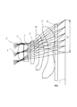
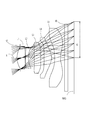
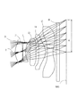
以下、本発明に係る実施形態について、図面を参照しながら詳細に説明する。図1、図3、図5、図7、図9、及び図11はそれぞれ、本実施形態の実施例1から6に係る撮像レンズの概略構成図を示している。いずれも基本的なレンズ構成は同様であるため、ここでは実施例1の概略構成図を参照しながら、本実施形態の撮像レンズ構成について説明する。 Hereinafter, embodiments according to the present invention will be described in detail with reference to the drawings. 1, FIG. 3, FIG. 5, FIG. 7, FIG. 9, and FIG. 11 show schematic configuration diagrams of imaging lenses according to Examples 1 to 6 of the present embodiment, respectively. Since the basic lens configuration is the same in all cases, the imaging lens configuration of the present embodiment will be described with reference to the schematic configuration diagram of Example 1.
図1に示すように、本発明に係る実施形態の撮像レンズは、固体撮像素子上に被写体の像を結像する撮像レンズであって、物体側から像面IMG側に向かって順に、開口絞りSTと、物体側と像面側に凸面を向けた正の屈折力を有する第1レンズL1と、像面側に凹面を向けた負の屈折力を有するメニスカス形状の第2レンズL2と、正の屈折力を有する少なくとも1面が非球面の第3レンズL3と、正の屈折力を有する両面が非球面の第4レンズL4と、光軸近傍で物体側と像面側に凹面を向けた負の屈折力を有する両面が非球面の第5レンズL5とから成り、第5レンズL5の像面側の面には、光軸X上以外の位置に変極点が形成されている。第5レンズL5と像面IMGとの間には、赤外線カットフィルタ等のフィルタIRが配置されている。なお、このフィルタIRは省略することも可能である。本実施形態における光学全長やバックフォーカスの値は、このフィルタIRを空気換算した値として定義している。 As shown in FIG. 1, the imaging lens according to the embodiment of the present invention is an imaging lens that forms an image of a subject on a solid-state imaging device, and the aperture stop in order from the object side to the image plane IMG side. ST, a first lens L1 having a positive refractive power with the convex surface facing the object side and the image surface side, a meniscus second lens L2 having a negative refractive power with the concave surface facing the image surface side, and a positive A third lens L3 having at least one aspherical surface and a fourth lens L4 having both aspherical surfaces having positive refractive power, and a concave surface facing the object side and the image plane side in the vicinity of the optical axis. Both surfaces having negative refractive power are composed of an aspherical fifth lens L5, and an inflection point is formed at a position other than on the optical axis X on the image side surface of the fifth lens L5. A filter IR such as an infrared cut filter is disposed between the fifth lens L5 and the image plane IMG. The filter IR can be omitted. The optical total length and the back focus value in this embodiment are defined as values obtained by converting the filter IR into air.
上記構成の撮像レンズは、物体側から順に、正、負、正、正、負で配列した、いわゆるテレフォトタイプに近い構成になっており、それぞれのレンズに最適な屈折力を配分することで低背化を実現している。第1レンズL1を両凸形状にすることで球面収差の発生を抑えながら、撮像レンズ全系に必要な正の屈折力を得、また、第5レンズL5の物体側の面と像面側の面を光軸Xの近傍で凹面にすることでテレフォトの傾向を強めている。また、第2レンズL2を像面側に凹面を向けたメニスカス形状とすることで、主に球面収差およびコマ収差の補正を効果的に行い、第3レンズL3、及び第4レンズL4に適切な正の屈折力を配分して低背化を維持しながら、レンズ面に形成した非球面によって、特に軸外の諸収差を補正する。また、第5レンズL5の像面側の面は、光軸X上以外の位置に変極点を有する非球面を形成しており、軸外における像面湾曲及び非点収差の補正を良好に行うとともに、撮像面IMGへ入射する主光線角度の制御を容易にしている。開口絞りは、第1レンズL1の物体側に配置しているため、射出瞳位置が像面から遠ざかり、撮像面IMGに近い第5レンズL5によるテレセントリック性確保の負担が軽減されている。なお、ここで言う変極点とは、接平面が光軸Xと垂直に交わる非球面上の点を意味する。 The imaging lens with the above configuration is arranged in order from the object side in the positive, negative, positive, positive, negative, so-called telephoto type configuration, and by distributing the optimum refractive power to each lens Low profile is realized. By making the first lens L1 a biconvex shape, the positive refractive power necessary for the entire imaging lens system is obtained while suppressing the occurrence of spherical aberration, and the object side surface and the image surface side of the fifth lens L5 are obtained. By making the surface concave in the vicinity of the optical axis X, the tendency of telephoto is strengthened. Further, by making the second lens L2 into a meniscus shape with the concave surface facing the image surface side, mainly correction of spherical aberration and coma aberration is effectively performed, which is suitable for the third lens L3 and the fourth lens L4. While distributing the positive refractive power and maintaining a low profile, various off-axis aberrations are corrected in particular by the aspherical surface formed on the lens surface. Further, the surface on the image plane side of the fifth lens L5 forms an aspheric surface having an inflection point at a position other than on the optical axis X, and corrects the field curvature and astigmatism off the axis well. At the same time, the control of the chief ray angle incident on the imaging surface IMG is facilitated. Since the aperture stop is disposed on the object side of the first lens L1, the exit pupil position is far from the image plane, and the burden of ensuring telecentricity by the fifth lens L5 close to the imaging plane IMG is reduced. The inflection point referred to here means a point on the aspheric surface where the tangent plane intersects the optical axis X perpendicularly.
また、本実施形態に係る撮像レンズにおいて、第3レンズL3は正の屈折力を備え、少なくとも1面に非球面形状が形成されたレンズであり、第4レンズL4は光軸Xの近傍で像面側に凸面を向けたメニスカス形状になっている。
In the imaging lens according to the present embodiment, the third lens L3 is a lens having a positive refractive power and an aspheric shape formed on at least one surface , and the fourth lens L4 is an image near the optical axis X. It has a meniscus shape with a convex surface facing the surface.
第3レンズL3を正の屈折力とし、少なくとも1面に非球面形状を形成することで、球面収差およびコマ収差の補正を好適に行っている。また、第4レンズL4を光軸Xの近傍で像面側に凸面を向けたメニスカス形状にすることによって、非点収差と像面湾曲の補正を好適に行っている。
By making the third lens L3 have a positive refractive power and forming an aspherical shape on at least one surface , spherical aberration and coma are corrected appropriately. Further, the astigmatism and the curvature of field are suitably corrected by forming the fourth lens L4 in the meniscus shape with the convex surface facing the image plane side in the vicinity of the optical axis X.
本実施形態の撮像レンズは、以下の条件式(1)から(8)を満足する。
(1)0.5<f1/f<1.0
(2)10.0<f3/f
(3)0.8<(r3+r4)/(r3−r4)<2.0
(4)0.4<f4/f<1.2
(5)−1.0<f5/f<−0.4
(6)20<νd1−νd2
(7)50<νd3,νd4,νd5<80
(8)ih/f>0.7
ただし、
f:撮像レンズ全系の焦点距離
f1:第1レンズL1の焦点距離
f3:第3レンズL3の焦点距離
f4:第4レンズL4の焦点距離
f5:第5レンズL5の焦点距離
r3:第2レンズL2の物体側の面の曲率半径
r4:第2レンズL2の像面側の面の曲率半径
νd1:第1レンズL1のd線に対するアッベ数
νd2:第2レンズL2のd線に対するアッベ数
νd3:第3レンズL3のd線に対するアッベ数
νd4:第4レンズL4のd線に対するアッベ数
νd5:第5レンズL5のd線に対するアッベ数
ih:最大像高
The imaging lens of the present embodiment satisfies the following conditional expressions (1) to (8).
(1) 0.5 <f1 / f <1.0
(2) 10.0 <f3 / f
(3) 0.8 <(r3 + r4) / (r3-r4) <2.0
(4) 0.4 <f4 / f <1.2
(5) -1.0 <f5 / f <-0.4
(6) 20 <νd1-νd2
(7) 50 <νd3, νd4, νd5 <80
(8) ih / f> 0.7
However,
f: focal length of the entire imaging lens f1: focal length of the first lens L1 f3: focal length of the third lens L3 f4: focal length of the fourth lens L4 f5: focal length of the fifth lens L5 r3: second lens The radius of curvature r4 of the object side surface of L2: The radius of curvature νd1: The Abbe number νd2 of the first lens L1 with respect to the d line νd2: The Abbe number νd3 of the second lens L2 with respect to the d line: Abbe number νd4 with respect to d line of third lens L3: Abbe number νd5 with respect to d line of fourth lens L4: Abbe number ih with respect to d line of fifth lens L5: maximum image height
条件式(1)を満足することにより、撮像レンズ全系の正の屈折力の大部分を第1レンズL1に担わせ、低背化と結像性能の両立が図られている。 By satisfying conditional expression (1), most of the positive refractive power of the entire imaging lens system is borne by the first lens L1, and both low profile and imaging performance are achieved.
条件式(2)を満足することで、撮像レンズ全系における第3レンズL3が補うべき正の屈折力を適切な範囲として、第3レンズL3で発生する収差を抑制している。 By satisfying conditional expression (2), the positive refractive power that should be compensated for by the third lens L3 in the entire imaging lens system is set within an appropriate range, and aberrations that occur in the third lens L3 are suppressed.
条件式(3)を満足することで、第2レンズL2の負の屈折力を第5レンズL5の負の屈折力と適切にバランスさせるとともに、第2レンズL2の片側の面に強い収差補正能力を発揮させることにより、第2レンズL2による収差補正機能を高めている。 By satisfying conditional expression (3), the negative refracting power of the second lens L2 is appropriately balanced with the negative refracting power of the fifth lens L5, and a strong aberration correction capability is provided on one surface of the second lens L2. As a result, the aberration correction function of the second lens L2 is enhanced.
条件式(4)を満足することで、撮像レンズ全系における第4レンズL4の正の屈折力が適切な範囲となり、第2レンズL2、及び第5レンズL5の負の屈折力とのバランスが良好な範囲に保たれている。その結果、テレフォト性を維持しながら、非点収差及び像面湾曲の補正効果を得ている。 By satisfying conditional expression (4), the positive refractive power of the fourth lens L4 in the entire imaging lens system is in an appropriate range, and the balance with the negative refractive power of the second lens L2 and the fifth lens L5 is balanced. It is kept in a good range. As a result, astigmatism and field curvature correction effects are obtained while maintaining telephoto properties.
条件式(5)を満足することで、撮像レンズ全系における第5レンズL5の負の屈折力が適切な範囲となり、撮像レンズ全系のテレフォト性を確保し、かつ軸上から軸外まで像面全域にわたって良好な画質を実現することを容易にしている。 By satisfying conditional expression (5), the negative refracting power of the fifth lens L5 in the entire imaging lens system is in an appropriate range, the telephoto property of the entire imaging lens system is ensured, and the image from on-axis to off-axis is obtained. It is easy to achieve good image quality over the entire surface.
また、アッベ数に関して、条件式(6)および(7)を満足することで、軸上色収差、及び倍率色収差が良好に補正されている。なお、条件式(6)、及び(7)の範囲の材料を選択することで、大量生産に向いたプラスチック材料の選択が可能となり、低コストの撮像レンズを得ることが可能となる。 Further, with respect to the Abbe number, the conditional chromatic aberration and the lateral chromatic aberration are satisfactorily corrected by satisfying conditional expressions (6) and (7). In addition, by selecting a material in the range of conditional expressions (6) and (7), it is possible to select a plastic material suitable for mass production, and it is possible to obtain a low-cost imaging lens.
また、条件式(8)を満足することで、撮像レンズの半画角が35°以上の比較的広角な撮像レンズを得ている。 Moreover, by satisfying conditional expression (8), a relatively wide-angle imaging lens having a half angle of view of 35 ° or more is obtained.
本実施形態では、すべてのレンズ面を非球面で形成している。これらのレンズ面に採用する非球面形状は光軸方向の軸をZ、光軸に直交する方向の高さをH、円錐係数をk、非球面係数をA4、A6、A8、A10、A12、A14、A16としたとき数式1により表わされる。 In the present embodiment, all lens surfaces are aspherical. The aspherical shape adopted for these lens surfaces is Z in the optical axis direction, H in the direction perpendicular to the optical axis, k in the conical coefficient, A4, A6, A8, A10, A12, When A14 and A16 are set, they are expressed by Equation 1.

次に本実施形態に係る撮像レンズの実施例を示す。各実施例において、fは撮像レンズ全系の焦点距離を、FnoはFナンバーを、ωは半画角を、ihは最大像高を、TLA、及びbfはフィルタIRを空気換算した際の光学全長、バックフォーカスをそれぞれ示す。また、iは物体側から数えた面番号、rは曲率半径、dは光軸上のレンズ面間の距離(面間隔)、Ndはd線(基準波長)の屈折率、νdはd線に対するアッベ数をそれぞれ示す。なお、非球面に関しては、面番号iの後に*(アスタリスク)の符号を付加して示す。 Next, examples of the imaging lens according to this embodiment will be described. In each embodiment, f is the focal length of the entire imaging lens system, Fno is the F number, ω is the half field angle, ih is the maximum image height, TLA, and bf are optical values when the filter IR is converted to air. Full length and back focus are shown respectively. Further, i is a surface number counted from the object side, r is a radius of curvature, d is a distance (surface interval) between lens surfaces on the optical axis, Nd is a refractive index of d-line (reference wavelength), and νd is relative to d-line. The Abbe numbers are shown. As for the aspherical surface, a surface number i is added after the symbol * (asterisk).
基本的なレンズデータを以下の表1に示す。 Basic lens data is shown in Table 1 below.
実施例1の撮像レンズは、以下の表2に示すように条件式(1)から(8)の全てを満たしている。 The imaging lens of Example 1 satisfies all conditional expressions (1) to (8) as shown in Table 2 below.
図2は実施例1の撮像レンズについて、球面収差(mm)、非点収差(mm)、歪曲収差(%)を示したものである。球面収差図は、F線(486nm)、d線(588nm)、C線(656nm)の各波長に対する収差量を示している。また、非点収差図にはサジタル像面S、タンジェンシャル像面Tにおけるd線の収差量をそれぞれ示している(図4、図6、図8、図10、図12においても同じ)。図2に示すように、各収差は良好に補正されていることが分かる。 FIG. 2 shows spherical aberration (mm), astigmatism (mm), and distortion (%) for the imaging lens of Example 1. The spherical aberration diagram shows the amount of aberration with respect to each wavelength of the F line (486 nm), the d line (588 nm), and the C line (656 nm). The astigmatism diagrams show the d-line aberration amounts on the sagittal image plane S and the tangential image plane T (the same applies to FIGS. 4, 6, 8, 10, and 12). As shown in FIG. 2, it can be seen that each aberration is well corrected.
また、光学全長TLAは3.28mmであり、5枚構成でありながら低背化が図られている。さらに、全画角で75°程度の広い画角とF2.5以下の明るさを達成している。 Further, the optical total length TLA is 3.28 mm, and the height is reduced despite the configuration of five sheets. Furthermore, a wide field angle of about 75 ° and a brightness of F2.5 or less are achieved in all the field angles.
基本的なレンズデータを以下の表3に示す。 Basic lens data is shown in Table 3 below.
実施例2の撮像レンズは、以下の表4に示すように条件式(1)から(8)の全てを満たしている。 The imaging lens of Example 2 satisfies all of the conditional expressions (1) to (8) as shown in Table 4 below.
図4は実施例2の撮像レンズについて、球面収差(mm)、非点収差(mm)、歪曲収差(%)を示したものである。図4に示すように、各収差は良好に補正されていることが分かる。 FIG. 4 shows spherical aberration (mm), astigmatism (mm), and distortion (%) for the imaging lens of Example 2. As shown in FIG. 4, it can be seen that each aberration is well corrected.
また、光学全長TLAは3.27mmであり、5枚構成でありながら低背化が図られている。さらに、全画角で75°程度の広い画角とF2.5以下の明るさを達成している。 Further, the optical total length TLA is 3.27 mm, and the height is reduced despite the configuration of five sheets. Furthermore, a wide field angle of about 75 ° and a brightness of F2.5 or less are achieved in all the field angles.
基本的なレンズデータを以下の表5に示す。 Basic lens data is shown in Table 5 below.
実施例3の撮像レンズは、以下の表6に示すように条件式(1)から(8)の全てを満たしている。 The imaging lens of Example 3 satisfies all conditional expressions (1) to (8) as shown in Table 6 below.
図6は実施例3の撮像レンズについて、球面収差(mm)、非点収差(mm)、歪曲収差(%)を示したものである。図6に示すように、各収差は良好に補正されていることが分かる。 FIG. 6 shows spherical aberration (mm), astigmatism (mm), and distortion (%) for the imaging lens of Example 3. As shown in FIG. 6, it can be seen that each aberration is corrected satisfactorily.
また、光学全長TLAは3.28mmであり、5枚構成でありながら低背化が図られている。さらに、全画角で75°程度の広い画角とF2.5以下の明るさを達成している。 Further, the optical total length TLA is 3.28 mm, and the height is reduced despite the configuration of five sheets. Furthermore, a wide field angle of about 75 ° and a brightness of F2.5 or less are achieved in all the field angles.
基本的なレンズデータを以下の表7に示す。 Basic lens data is shown in Table 7 below.
実施例4の撮像レンズは、以下の表8に示すように条件式(1)から(8)の全てを満たしている。 The imaging lens of Example 4 satisfies all conditional expressions (1) to (8) as shown in Table 8 below.
図8は実施例4の撮像レンズについて、球面収差(mm)、非点収差(mm)、歪曲収差(%)を示したものである。図8に示すように、各収差は良好に補正されていることが分かる。 FIG. 8 shows spherical aberration (mm), astigmatism (mm), and distortion (%) for the imaging lens of Example 4. As shown in FIG. 8, it can be seen that each aberration is corrected satisfactorily.
また、光学全長TLAは3.30mmであり、5枚構成でありながら低背化が図られている。さらに、全画角で75°程度の広い画角とF2.5以下の明るさを達成している。 Further, the optical total length TLA is 3.30 mm, and the height is reduced while the configuration is five sheets. Furthermore, a wide field angle of about 75 ° and a brightness of F2.5 or less are achieved in all the field angles.
基本的なレンズデータを以下の表9に示す。
Basic lens data is shown in Table 9 below.
実施例5の撮像レンズは、以下の表10に示すように条件式(1)から(8)の全てを満たしている。
The imaging lens of Example 5 satisfies all of the conditional expressions (1) to (8) as shown in Table 10 below.
図10は実施例5の撮像レンズについて、球面収差(mm)、非点収差(mm)、歪曲収差(%)を示したものである。図10に示すように、各収差は良好に補正されていることが分かる。 FIG. 10 shows spherical aberration (mm), astigmatism (mm), and distortion (%) for the imaging lens of Example 5. As shown in FIG. 10, it can be seen that each aberration is corrected satisfactorily.
また、光学全長TLAは3.55mmであり、5枚構成でありながら低背化が図られている。さらに、全画角で75°程度の広い画角とF2.0の明るさを達成している。 Further, the optical total length TLA is 3.55 mm, and a low profile is achieved though it is a five-sheet configuration. Furthermore, a wide field angle of about 75 ° and a brightness of F2.0 are achieved at all angles.
基本的なレンズデータを以下の表11に示す。
Basic lens data is shown in Table 11 below.
実施例6の撮像レンズは、以下の表12に示すように条件式(1)から(8)の全てを満たしている。
The imaging lens of Embodiment 6, meets all Table 1 2 shows as conditional formulas (1) to (8) below.
図12は実施例6の撮像レンズについて、球面収差(mm)、非点収差(mm)、歪曲収差(%)を示したものである。図12に示すように、各収差は良好に補正されていることが分かる。
FIG. 12 shows spherical aberration (mm), astigmatism (mm), and distortion (%) for the imaging lens of Example 6 . As shown in FIG. 12, it can be seen that each aberration is corrected satisfactorily.
また、光学全長TLAは3.55mmであり、5枚構成でありながら低背化が図られている。さらに、全画角で75°程度の広い画角とF2.0の明るさを達成している。 Further, the optical total length TLA is 3.55 mm, and a low profile is achieved though it is a five-sheet configuration. Furthermore, a wide field angle of about 75 ° and a brightness of F2.0 are achieved at all angles.
以上、説明したように、本発明の実施形態に係る撮像レンズは、近年益々要求が強まる低背化に対して、5枚という構成枚数を採りながらも、光学全長TLAは4mm以下、光学全長TLAと最大像高ihとの比(TLA/2ih)で表せば0.8以下のレベルにまで低背化された撮像レンズを実現するとともに、全画角で75°程度の広い画角とF2.5以下の明るさに対応しながらも諸収差が良好に補正され、且つ低コストの撮像レンズを可能にする。 As described above, the imaging lens according to the embodiment of the present invention has an optical total length TLA of 4 mm or less and an optical total length TLA, while adopting the number of components of five in response to the low profile that has been increasingly demanded in recent years. And the maximum image height ih (TLA / 2ih), an imaging lens that is reduced in height to a level of 0.8 or less is realized, and a wide field angle of about 75 ° in all angles of view is obtained. Various aberrations are satisfactorily corrected while corresponding to a brightness of 5 or less, and a low-cost imaging lens is enabled.
本発明の各実施の形態に係る5枚構成の撮像レンズは、小型化、薄型化が進むスマートフォンや携帯電話機およびPDA(Personal Digital Assistant)などの携帯端末機器等、ゲーム機やPCなどの情報端末機器等、更にはカメラ機能が付加された家電製品等に搭載される撮像装置に内蔵する光学系に適用した場合、高性能なカメラ機能を維持しながら、当該装置の低背化の実現を図ることができる。 An imaging lens having a five-lens configuration according to each embodiment of the present invention is an information terminal such as a game machine or a PC, such as a mobile terminal device such as a smart phone, a mobile phone, and a PDA (Personal Digital Assistant) that is becoming smaller and thinner. When applied to an optical system built into an imaging device mounted on a device or the like, or a household electrical appliance with a camera function, etc., the height of the device is reduced while maintaining a high-performance camera function. be able to.
ST 開口絞り
L1 第1レンズ
L2 第2レンズ
L3 第3レンズ
L4 第4レンズ
L5 第5レンズ
IR フィルタ
IMG 撮像面
ih 撮像素子の有効撮像面の対角線の半分の長さ(最大像高)
ST Aperture stop L1 First lens L2 Second lens L3 Third lens L4 Fourth lens L5 Fifth lens IR filter IMG Imaging surface ih Half length of diagonal of effective imaging surface of imaging device (maximum image height)
Claims (3)
(1)0.5<f1/f<1.0
(2)10.0<f3/f
(3)0.8<(r3+r4)/(r3−r4)≦1.67
(6)20<νd1−νd2
(7)50<νd3,νd4,νd5<80
(8)ih/f>0.7
ただし、
f:撮像レンズ全系の焦点距離
f1:第1レンズの焦点距離
f3:第3レンズの焦点距離
r3:第2レンズの物体側の面の曲率半径
r4:第2レンズの像面側の面の曲率半径
νd1:第1レンズのd線に対するアッベ数
νd2:第2レンズのd線に対するアッベ数
νd3:第3レンズのd線に対するアッベ数
νd4:第4レンズのd線に対するアッベ数
νd5:第5レンズのd線に対するアッベ数
ih:最大像高
An imaging lens that forms an image of a subject on a solid-state imaging device, and has an aperture stop and a positive refractive power with convex surfaces facing the object side and the image plane side in order from the object side to the image plane side A first lens, a second meniscus lens having negative refractive power with a concave surface facing the image surface side, a third lens having at least one aspheric surface having positive refractive power, and positive refractive power sided non sided with having a fourth lens of a meniscus shape with a convex surface directed toward the image side near the optical axis aspherical, the negative refractive power with a concave surface facing the object side and the image side near the optical axis The inflection point is formed at a position other than on the optical axis on the surface on the image plane side of the fifth lens. The following conditional expressions (1) to (3) and (3) 6. An imaging lens characterized by satisfying (8) to (8).
(1) 0.5 <f1 / f <1.0
(2) 10.0 <f3 / f
(3) 0.8 <(r3 + r4) / (r3-r4) ≦ 1.67
(6) 20 <νd1-νd2
(7) 50 <νd3, νd4, νd5 <80
(8) ih / f> 0.7
However,
f: focal length of the entire imaging lens f1: focal length of the first lens f3: focal length of the third lens r3: radius of curvature of the object side surface of the second lens r4: surface of the image surface side of the second lens Radius of curvature νd1: Abbe number νd2 for d-line of first lens: Abbe number νd3 for d-line of second lens: Abbe number νd4 for d-line of third lens: Abbe number νd5 for d-line of fourth lens: fifth Abbe number ih for lens d-line: maximum image height
(4) 0.4<f4/f<1.2(4) 0.4 <f4 / f <1.2
ただし、However,
f:撮像レンズ全系の焦点距離f: Focal length of the entire imaging lens system
f4:第4レンズの焦点距離f4: focal length of the fourth lens
(5)−1.0<f5/f<−0.4
ただし、
f:撮像レンズ全系の焦点距離
f5:第5レンズの焦点距離
And satisfies the following conditional expression (5), the imaging lens according to claim 1 or 2.
(5) -1.0 <f5 / f <-0.4
However,
f: Focal length of the entire imaging lens system
f5: focal length of the fifth lens
Priority Applications (3)
| Application Number | Priority Date | Filing Date | Title |
|---|---|---|---|
| JP2013245869A JP5818866B2 (en) | 2013-11-28 | 2013-11-28 | Imaging lens |
| CN201420375551.1U CN204086668U (en) | 2013-11-28 | 2014-07-08 | Pick-up lens |
| US14/474,527 US9575288B2 (en) | 2013-11-28 | 2014-09-02 | Imaging lens |
Applications Claiming Priority (1)
| Application Number | Priority Date | Filing Date | Title |
|---|---|---|---|
| JP2013245869A JP5818866B2 (en) | 2013-11-28 | 2013-11-28 | Imaging lens |
Publications (3)
| Publication Number | Publication Date |
|---|---|
| JP2015102850A JP2015102850A (en) | 2015-06-04 |
| JP2015102850A5 JP2015102850A5 (en) | 2015-07-23 |
| JP5818866B2 true JP5818866B2 (en) | 2015-11-18 |
Family
ID=52179368
Family Applications (1)
| Application Number | Title | Priority Date | Filing Date |
|---|---|---|---|
| JP2013245869A Active JP5818866B2 (en) | 2013-11-28 | 2013-11-28 | Imaging lens |
Country Status (3)
| Country | Link |
|---|---|
| US (1) | US9575288B2 (en) |
| JP (1) | JP5818866B2 (en) |
| CN (1) | CN204086668U (en) |
Families Citing this family (11)
| Publication number | Priority date | Publication date | Assignee | Title |
|---|---|---|---|---|
| TWI545365B (en) | 2015-02-17 | 2016-08-11 | 大立光電股份有限公司 | Image capturing lens assembly, image capturing device and electronic device |
| JP5807137B1 (en) * | 2015-07-24 | 2015-11-10 | エーエーシーアコースティックテクノロジーズ(シンセン)カンパニーリミテッドAAC Acoustic Technologies(Shenzhen)Co.,Ltd | Imaging lens |
| CN109856781B (en) * | 2016-01-13 | 2020-12-29 | 大立光电股份有限公司 | Optical lens group for imaging |
| JP5986696B1 (en) * | 2016-06-16 | 2016-09-06 | エーエーシー テクノロジーズ ピーティーイー リミテッドAac Technologies Pte.Ltd. | Imaging lens |
| CN106802470B (en) * | 2016-12-14 | 2019-07-05 | 瑞声科技(新加坡)有限公司 | Camera optical camera lens |
| CN107193108B (en) * | 2017-03-24 | 2019-10-15 | 玉晶光电(厦门)有限公司 | Optical imaging lens |
| US11493734B2 (en) * | 2017-06-13 | 2022-11-08 | Zhejiang Sunny Optical Co., Ltd | Camera lens assembly including five lenses of +−++− or +−−+− refractive powers |
| US10209492B1 (en) * | 2017-12-29 | 2019-02-19 | AAC Technologies Pte. Ltd. | Camera optical lens |
| CN108572432B (en) | 2018-05-03 | 2023-06-06 | 浙江舜宇光学有限公司 | Optical imaging system |
| JP6551873B1 (en) * | 2018-08-14 | 2019-07-31 | エーエーシー テクノロジーズ ピーティーイー リミテッド | Imaging optical lens |
| CN113376816B (en) * | 2021-06-18 | 2022-05-27 | 青岛理工大学 | Aspheric surface short wave infrared lens |
Family Cites Families (26)
| Publication number | Priority date | Publication date | Assignee | Title |
|---|---|---|---|---|
| JP5298682B2 (en) | 2008-07-24 | 2013-09-25 | コニカミノルタ株式会社 | Imaging lens |
| CN103033911A (en) * | 2008-08-25 | 2013-04-10 | 柯尼卡美能达精密光学株式会社 | Imaging lens, imaging device and portable terminal |
| KR101081187B1 (en) * | 2008-10-20 | 2011-11-07 | 엘지이노텍 주식회사 | Imaging Lens |
| JP5607398B2 (en) * | 2009-04-07 | 2014-10-15 | 富士フイルム株式会社 | IMAGING LENS, IMAGING DEVICE, AND PORTABLE TERMINAL DEVICE |
| JP5371148B2 (en) * | 2009-06-04 | 2013-12-18 | 株式会社オプトロジック | Imaging lens |
| WO2011021271A1 (en) * | 2009-08-18 | 2011-02-24 | コニカミノルタオプト株式会社 | Imaging lens, imaging device, and portable terminal |
| JP5426313B2 (en) | 2009-10-15 | 2014-02-26 | 日立マクセル株式会社 | Imaging lens system |
| TWI422900B (en) * | 2010-12-23 | 2014-01-11 | Largan Precision Co Ltd | Photographing optical lens assembly |
| KR101276534B1 (en) * | 2011-02-17 | 2013-06-24 | 주식회사 코렌 | Photographic lens optical system |
| TWI407183B (en) * | 2011-02-22 | 2013-09-01 | Largan Precision Co Ltd | Image capturing lens assembly |
| WO2012176379A1 (en) * | 2011-06-24 | 2012-12-27 | コニカミノルタアドバンストレイヤー株式会社 | Image pickup optical system, image pickup device, and digital apparatus |
| TWI437257B (en) * | 2011-08-04 | 2014-05-11 | Largan Precision Co | Optical lens assembly for imaging pickup |
| KR101321276B1 (en) * | 2011-10-21 | 2013-10-28 | 삼성전기주식회사 | Imaging lens |
| WO2013172164A1 (en) * | 2012-05-14 | 2013-11-21 | コニカミノルタ株式会社 | Image-capturing lens |
| US8913332B2 (en) | 2012-09-05 | 2014-12-16 | Kolen Co., Ltd. | Photographing lens optical system |
| TWI487934B (en) * | 2012-10-12 | 2015-06-11 | 玉晶光電股份有限公司 | Mobile device and optical imaging lens thereof |
| CN103076672A (en) * | 2012-10-12 | 2013-05-01 | 玉晶光电(厦门)有限公司 | Portable electronic device and optical imaging lens thereof |
| CN103885157B (en) * | 2012-12-21 | 2017-07-28 | 柯尼卡美能达株式会社 | Taking lens |
| JP2014142499A (en) * | 2013-01-24 | 2014-08-07 | Konica Minolta Inc | Imaging lens, imaging optical device, and digital equipment |
| CN103293638B (en) * | 2013-02-06 | 2016-03-23 | 玉晶光电(厦门)有限公司 | Optical imaging lens and apply the electronic installation of this camera lens |
| CN103293637B (en) * | 2013-02-06 | 2016-05-11 | 玉晶光电(厦门)有限公司 | Five chip optical imaging lens and apply the electronic installation of this camera lens |
| JP2014153577A (en) * | 2013-02-08 | 2014-08-25 | Konica Minolta Inc | Imaging lens, and imaging device and portable terminal |
| JP2014153576A (en) * | 2013-02-08 | 2014-08-25 | Konica Minolta Inc | Imaging lens, and imaging device and portable terminal |
| JP2014153575A (en) * | 2013-02-08 | 2014-08-25 | Konica Minolta Inc | Imaging lens, and imaging device and portable terminal |
| JP2014163970A (en) * | 2013-02-21 | 2014-09-08 | Konica Minolta Inc | Image capturing optical system unit, image capturing device, and digital device |
| JP2015084066A (en) * | 2013-09-20 | 2015-04-30 | コニカミノルタ株式会社 | Image capturing lens, image capturing device, and portable terminal |
-
2013
- 2013-11-28 JP JP2013245869A patent/JP5818866B2/en active Active
-
2014
- 2014-07-08 CN CN201420375551.1U patent/CN204086668U/en not_active Expired - Lifetime
- 2014-09-02 US US14/474,527 patent/US9575288B2/en active Active
Also Published As
| Publication number | Publication date |
|---|---|
| US9575288B2 (en) | 2017-02-21 |
| JP2015102850A (en) | 2015-06-04 |
| CN204086668U (en) | 2015-01-07 |
| US20150146306A1 (en) | 2015-05-28 |
Similar Documents
| Publication | Publication Date | Title |
|---|---|---|
| JP6226376B2 (en) | Imaging lens | |
| JP6573315B2 (en) | Imaging lens | |
| JP6226377B2 (en) | Imaging lens | |
| JP6403711B2 (en) | Imaging lens | |
| JP6351171B2 (en) | Imaging lens with 7 optical elements | |
| JP6256946B2 (en) | Imaging lens with 6 optical elements | |
| JP6324830B2 (en) | Imaging lens | |
| JP6355236B2 (en) | Imaging lens with 6 optical elements | |
| JP5818866B2 (en) | Imaging lens | |
| JP6021617B2 (en) | Imaging lens | |
| JP6105317B2 (en) | Wide-angle imaging lens | |
| CN106054354B (en) | Camera lens | |
| JP6376561B2 (en) | Imaging lens | |
| JP6133068B2 (en) | Imaging lens | |
| JP6226369B2 (en) | Wide-angle imaging lens | |
| JP5963360B2 (en) | Imaging lens | |
| JP5992868B2 (en) | Imaging device | |
| JP6300410B2 (en) | Imaging lens | |
| JP6324824B2 (en) | Imaging lens | |
| JP6144954B2 (en) | Imaging lens | |
| JP6332851B2 (en) | Imaging lens | |
| JP6257080B2 (en) | Imaging lens with 6 optical elements | |
| JP6566492B2 (en) | Imaging lens | |
| JP6274942B2 (en) | Imaging lens with 5 optical elements | |
| JP6202569B2 (en) | Imaging lens |
Legal Events
| Date | Code | Title | Description |
|---|---|---|---|
| A521 | Request for written amendment filed |
Free format text: JAPANESE INTERMEDIATE CODE: A523 Effective date: 20150605 |
|
| A621 | Written request for application examination |
Free format text: JAPANESE INTERMEDIATE CODE: A621 Effective date: 20150605 |
|
| A871 | Explanation of circumstances concerning accelerated examination |
Free format text: JAPANESE INTERMEDIATE CODE: A871 Effective date: 20150605 |
|
| A977 | Report on retrieval |
Free format text: JAPANESE INTERMEDIATE CODE: A971007 Effective date: 20150812 |
|
| A975 | Report on accelerated examination |
Free format text: JAPANESE INTERMEDIATE CODE: A971005 Effective date: 20150818 |
|
| A131 | Notification of reasons for refusal |
Free format text: JAPANESE INTERMEDIATE CODE: A131 Effective date: 20150826 |
|
| A521 | Request for written amendment filed |
Free format text: JAPANESE INTERMEDIATE CODE: A523 Effective date: 20150908 |
|
| TRDD | Decision of grant or rejection written | ||
| A01 | Written decision to grant a patent or to grant a registration (utility model) |
Free format text: JAPANESE INTERMEDIATE CODE: A01 Effective date: 20150929 |
|
| A61 | First payment of annual fees (during grant procedure) |
Free format text: JAPANESE INTERMEDIATE CODE: A61 Effective date: 20150929 |
|
| R150 | Certificate of patent or registration of utility model |
Ref document number: 5818866 Country of ref document: JP Free format text: JAPANESE INTERMEDIATE CODE: R150 |
|
| R250 | Receipt of annual fees |
Free format text: JAPANESE INTERMEDIATE CODE: R250 |
|
| R250 | Receipt of annual fees |
Free format text: JAPANESE INTERMEDIATE CODE: R250 |
|
| S531 | Written request for registration of change of domicile |
Free format text: JAPANESE INTERMEDIATE CODE: R313531 |
|
| R350 | Written notification of registration of transfer |
Free format text: JAPANESE INTERMEDIATE CODE: R350 |
|
| R250 | Receipt of annual fees |
Free format text: JAPANESE INTERMEDIATE CODE: R250 |
|
| S111 | Request for change of ownership or part of ownership |
Free format text: JAPANESE INTERMEDIATE CODE: R313113 |
|
| R371 | Transfer withdrawn |
Free format text: JAPANESE INTERMEDIATE CODE: R371 |
|
| S111 | Request for change of ownership or part of ownership |
Free format text: JAPANESE INTERMEDIATE CODE: R313113 |
|
| R350 | Written notification of registration of transfer |
Free format text: JAPANESE INTERMEDIATE CODE: R350 |
|
| R250 | Receipt of annual fees |
Free format text: JAPANESE INTERMEDIATE CODE: R250 |
|
| R250 | Receipt of annual fees |
Free format text: JAPANESE INTERMEDIATE CODE: R250 |
|
| S531 | Written request for registration of change of domicile |
Free format text: JAPANESE INTERMEDIATE CODE: R313531 |
|
| R250 | Receipt of annual fees |
Free format text: JAPANESE INTERMEDIATE CODE: R250 |
|
| R350 | Written notification of registration of transfer |
Free format text: JAPANESE INTERMEDIATE CODE: R350 |