JP5815308B2 - Disc brake - Google Patents

Disc brake Download PDF

Info

Publication number
JP5815308B2
JP5815308B2 JP2011146793A JP2011146793A JP5815308B2 JP 5815308 B2 JP5815308 B2 JP 5815308B2 JP 2011146793 A JP2011146793 A JP 2011146793A JP 2011146793 A JP2011146793 A JP 2011146793A JP 5815308 B2 JP5815308 B2 JP 5815308B2
Authority
JP
Japan
Prior art keywords
piston
friction pad
disk
disc
pressing
Prior art date
Legal status (The legal status is an assumption and is not a legal conclusion. Google has not performed a legal analysis and makes no representation as to the accuracy of the status listed.)
Expired - Fee Related
Application number
JP2011146793A
Other languages
Japanese (ja)
Other versions
JP2013015164A5 (en
JP2013015164A (en
Inventor
聖子 坪田
聖子 坪田
久米村 洋一
洋一 久米村
映 井上
映 井上
吉田 仁
仁 吉田
Current Assignee (The listed assignees may be inaccurate. Google has not performed a legal analysis and makes no representation or warranty as to the accuracy of the list.)
Hitachi Astemo Ltd
Original Assignee
Hitachi Automotive Systems Ltd
Priority date (The priority date is an assumption and is not a legal conclusion. Google has not performed a legal analysis and makes no representation as to the accuracy of the date listed.)
Filing date
Publication date
Application filed by Hitachi Automotive Systems Ltd filed Critical Hitachi Automotive Systems Ltd
Priority to JP2011146793A priority Critical patent/JP5815308B2/en
Priority to DE201210210985 priority patent/DE102012210985A1/en
Priority to CN201210223571.2A priority patent/CN102852999B/en
Priority to US13/537,620 priority patent/US9027716B2/en
Publication of JP2013015164A publication Critical patent/JP2013015164A/en
Publication of JP2013015164A5 publication Critical patent/JP2013015164A5/ja
Application granted granted Critical
Publication of JP5815308B2 publication Critical patent/JP5815308B2/en
Expired - Fee Related legal-status Critical Current
Anticipated expiration legal-status Critical

Links

Images

Classifications

    • FMECHANICAL ENGINEERING; LIGHTING; HEATING; WEAPONS; BLASTING
    • F16ENGINEERING ELEMENTS AND UNITS; GENERAL MEASURES FOR PRODUCING AND MAINTAINING EFFECTIVE FUNCTIONING OF MACHINES OR INSTALLATIONS; THERMAL INSULATION IN GENERAL
    • F16DCOUPLINGS FOR TRANSMITTING ROTATION; CLUTCHES; BRAKES
    • F16D55/00Brakes with substantially-radial braking surfaces pressed together in axial direction, e.g. disc brakes
    • F16D55/02Brakes with substantially-radial braking surfaces pressed together in axial direction, e.g. disc brakes with axially-movable discs or pads pressed against axially-located rotating members
    • F16D55/22Brakes with substantially-radial braking surfaces pressed together in axial direction, e.g. disc brakes with axially-movable discs or pads pressed against axially-located rotating members by clamping an axially-located rotating disc between movable braking members, e.g. movable brake discs or brake pads
    • F16D55/224Brakes with substantially-radial braking surfaces pressed together in axial direction, e.g. disc brakes with axially-movable discs or pads pressed against axially-located rotating members by clamping an axially-located rotating disc between movable braking members, e.g. movable brake discs or brake pads with a common actuating member for the braking members
    • F16D55/225Brakes with substantially-radial braking surfaces pressed together in axial direction, e.g. disc brakes with axially-movable discs or pads pressed against axially-located rotating members by clamping an axially-located rotating disc between movable braking members, e.g. movable brake discs or brake pads with a common actuating member for the braking members the braking members being brake pads
    • F16D55/226Brakes with substantially-radial braking surfaces pressed together in axial direction, e.g. disc brakes with axially-movable discs or pads pressed against axially-located rotating members by clamping an axially-located rotating disc between movable braking members, e.g. movable brake discs or brake pads with a common actuating member for the braking members the braking members being brake pads in which the common actuating member is moved axially, e.g. floating caliper disc brakes
    • FMECHANICAL ENGINEERING; LIGHTING; HEATING; WEAPONS; BLASTING
    • F16ENGINEERING ELEMENTS AND UNITS; GENERAL MEASURES FOR PRODUCING AND MAINTAINING EFFECTIVE FUNCTIONING OF MACHINES OR INSTALLATIONS; THERMAL INSULATION IN GENERAL
    • F16DCOUPLINGS FOR TRANSMITTING ROTATION; CLUTCHES; BRAKES
    • F16D65/00Parts or details
    • F16D65/0006Noise or vibration control
    • FMECHANICAL ENGINEERING; LIGHTING; HEATING; WEAPONS; BLASTING
    • F16ENGINEERING ELEMENTS AND UNITS; GENERAL MEASURES FOR PRODUCING AND MAINTAINING EFFECTIVE FUNCTIONING OF MACHINES OR INSTALLATIONS; THERMAL INSULATION IN GENERAL
    • F16DCOUPLINGS FOR TRANSMITTING ROTATION; CLUTCHES; BRAKES
    • F16D65/00Parts or details
    • F16D65/02Braking members; Mounting thereof
    • F16D65/04Bands, shoes or pads; Pivots or supporting members therefor
    • F16D65/092Bands, shoes or pads; Pivots or supporting members therefor for axially-engaging brakes, e.g. disc brakes
    • F16D65/095Pivots or supporting members therefor
    • F16D65/097Resilient means interposed between pads and supporting members or other brake parts
    • F16D65/0971Resilient means interposed between pads and supporting members or other brake parts transmitting brake actuation force, e.g. elements interposed between brake piston and pad
    • FMECHANICAL ENGINEERING; LIGHTING; HEATING; WEAPONS; BLASTING
    • F16ENGINEERING ELEMENTS AND UNITS; GENERAL MEASURES FOR PRODUCING AND MAINTAINING EFFECTIVE FUNCTIONING OF MACHINES OR INSTALLATIONS; THERMAL INSULATION IN GENERAL
    • F16DCOUPLINGS FOR TRANSMITTING ROTATION; CLUTCHES; BRAKES
    • F16D65/00Parts or details
    • F16D65/14Actuating mechanisms for brakes; Means for initiating operation at a predetermined position
    • F16D65/16Actuating mechanisms for brakes; Means for initiating operation at a predetermined position arranged in or on the brake
    • F16D65/18Actuating mechanisms for brakes; Means for initiating operation at a predetermined position arranged in or on the brake adapted for drawing members together, e.g. for disc brakes
    • FMECHANICAL ENGINEERING; LIGHTING; HEATING; WEAPONS; BLASTING
    • F16ENGINEERING ELEMENTS AND UNITS; GENERAL MEASURES FOR PRODUCING AND MAINTAINING EFFECTIVE FUNCTIONING OF MACHINES OR INSTALLATIONS; THERMAL INSULATION IN GENERAL
    • F16DCOUPLINGS FOR TRANSMITTING ROTATION; CLUTCHES; BRAKES
    • F16D2121/00Type of actuator operation force
    • F16D2121/02Fluid pressure
    • F16D2121/04Fluid pressure acting on a piston-type actuator, e.g. for liquid pressure

Landscapes

  • Engineering & Computer Science (AREA)
  • General Engineering & Computer Science (AREA)
  • Mechanical Engineering (AREA)
  • Braking Arrangements (AREA)

Description

本発明は、例えば自動車等の車両に制動力を付与するディスクブレーキに関する。   The present invention relates to a disc brake that applies a braking force to a vehicle such as an automobile.

一般に、自動車等の車両に設けられるディスクブレーキは、車両の固定部に対して回転可能なディスクの外周側をディスク軸方向に跨いで配置されるキャリパと、該キャリパのディスク軸方向の少なくとも一側に設けられているピストンと、該ピストンによりディスクの両面に押圧される一対の摩擦パッドとを備えて構成されている(例えば、特許文献1参照)。   Generally, a disc brake provided in a vehicle such as an automobile includes a caliper that is disposed across the outer peripheral side of a disc that can rotate with respect to a fixed portion of the vehicle in the disc axial direction, and at least one side of the caliper in the disc axial direction. And a pair of friction pads pressed against both sides of the disk by the piston (see, for example, Patent Document 1).

車両の運転者等がブレーキ操作を行ったときは、例えばピストンを外部からの液圧供給によりディスク側に摺動変位させ、該ピストンによって摩擦パッドをディスクに向けて押圧することにより、該ディスクに制動力を付与する構成となっている。   When a driver or the like of a vehicle performs a brake operation, for example, the piston is slid and displaced toward the disk side by supplying hydraulic pressure from the outside, and the friction pad is pressed toward the disk by the piston. It is the structure which gives braking force.

特開2010−175040号公報JP 2010-175040 A

ディスクブレーキは、例えば摩擦パッドが新品のときから交換の時期に至るまで、ブレーキ鳴きを抑制できることが望ましい。特に、ブレーキペダルに少し足を載せた程度、換言すれば、ディスクに摩擦パッドが当たり始める程度の微圧領域の制動時に、微圧鳴きと呼ばれるブレーキ鳴きが発生することを安定して抑制できることが望ましい。   The disc brake is desirably capable of suppressing brake squeal, for example, from when the friction pad is new to when it is replaced. In particular, it is possible to stably suppress the occurrence of a brake squeal called a micro-squeal when braking in a micro-pressure region where a foot is placed on the brake pedal, in other words, a friction pad starts to hit the disc. desirable.

本発明の目的は、微圧領域の制動時のブレーキ鳴きを抑制できるようにしたディスクブレーキを提供することにある。   An object of the present invention is to provide a disc brake capable of suppressing brake squeal during braking in a low pressure region.

上述した課題を解決するため本発明は、車両の固定部に対して回転可能なディスクの外周側をディスク軸方向に跨いで配置されるキャリパと、該キャリパのディスク軸方向の少なくとも一側に設けられているピストンと、該ピストンにより前記ディスクの両面に押圧される一対の摩擦パッドとを備えてなるディスクブレーキに適用される。   In order to solve the above-described problems, the present invention is provided with a caliper that is disposed across the outer peripheral side of a disc that can rotate relative to a fixed portion of a vehicle in the disc axial direction, and at least one side of the caliper in the disc axial direction. The present invention is applied to a disc brake that includes a piston and a pair of friction pads that are pressed against both sides of the disc by the piston.

そして、本発明が採用する構成の特徴は、前記ピストンと前記摩擦パッドとの間には、前記ピストンが前記摩擦パッドを押圧し始めたとき、前記ピストンのディスク周方向中央で該摩擦パッドを押圧する押圧機構を設け、該押圧機構は、前記摩擦パッドのディスク周方向中央で前記ディスク径方向に延び前記摩擦パッドに当接する当接部と、該当接部の両端にそれぞれ離間して設けられ、ディスク径方向に沿って切起こされると共に弾性力を有する第1および第2の突出部と、を備える構成としたことにある。 A feature of the configuration adopted by the present invention is that when the piston starts to press the friction pad between the piston and the friction pad, the friction pad is pressed at the center in the disk circumferential direction of the piston. a pressing mechanism is provided, push pressure mechanism, spaced apart each of the abutment portion abutting the disk circumferential direction central portion to the friction pad extending to the disk radial direction of the friction pad, on both ends of the abutting portions of is, lies in the first and second protrusions having an elastic force with caused switching along the disk radial direction, a structure in which Ru comprising a.

本発明によれば、微圧領域の制動時のブレーキ鳴きを抑制することができる。   According to the present invention, it is possible to suppress brake squeal during braking in the low pressure region.

本発明の第1の実施の形態によるディスクブレーキを示す縦断面図である。1 is a longitudinal sectional view showing a disc brake according to a first embodiment of the present invention. インナ側の摩擦パッドとシム板をインナ側(図1の右方向)からみた斜視図である。It is the perspective view which looked at the friction pad and shim board of the inner side from the inner side (right direction of FIG. 1). インナ側の摩擦パッドとシム板をインナ側からみた正面図である。It is the front view which looked at the friction pad and shim board on the inner side from the inner side. インナ側の摩擦パッドとシム板を示す図2の分解斜視図である。FIG. 3 is an exploded perspective view of FIG. 2 showing an inner friction pad and a shim plate. 微圧領域の状態のピストンと摩擦パッドとシム板を示す図3中の矢示V−V方向からみた断面図である。It is sectional drawing seen from the arrow VV direction in FIG. 3 which shows the piston of the state of a micro pressure area | region, a friction pad, and a shim board. 微圧領域を超えた状態のピストンと摩擦パッドとシム板を示す図5と同様位置の断面図である。It is sectional drawing of the same position as FIG. 5 which shows the piston, the friction pad, and shim board of the state beyond the micro pressure area | region. 本発明の第2の実施の形態によるインナ側の摩擦パッドとシム板を示す図3と同様位置の正面図である。It is a front view of the same position as FIG. 3 which shows the friction pad and shim board by the side of the inner side by the 2nd Embodiment of this invention. 微圧領域の状態のピストンと摩擦パッドとシム板を示す図7中の矢示VIII−VIII方向からみた断面図である。It is sectional drawing seen from the arrow VIII-VIII direction in FIG. 7 which shows the piston, friction pad, and shim board of the state of a micro pressure area | region. 本発明の第3の実施の形態によるインナ側の摩擦パッドとシム板を示す図3と同様位置の正面図である。It is a front view of the same position as FIG. 3 which shows the friction pad and shim board by the side of the inner side by the 3rd Embodiment of this invention. ピストンと摩擦パッドとシム板を示す図9中の矢示X−X方向からみた底面図である。It is a bottom view seen from the arrow XX direction in FIG. 9 which shows a piston, a friction pad, and a shim board. アウタ側の摩擦パッドとシム板を示すアウタ側(図1の左方向)からみた正面図である。It is the front view seen from the outer side (left direction of FIG. 1) which shows the friction pad and shim board of an outer side. キャリパのアウタ脚部(爪部)と摩擦パッドとシム板を示す図11中の矢示XII−XII方向からみた底面図である。It is a bottom view seen from the arrow XII-XII direction in FIG. 11 which shows the outer leg part (claw part) of a caliper, a friction pad, and a shim board. 本発明の第4の実施の形態によるインナ側の摩擦パッドとシム板と示す図3と同様位置の正面図である。It is a front view of the same position as FIG. 3 which shows the friction pad and shim board by the inner side by the 4th Embodiment of this invention. ピストンと摩擦パッドとシム板を示す図13中の矢示XIV−XIV方向からみた底面図である。It is a bottom view seen from the arrow XIV-XIV direction in FIG. 13 which shows a piston, a friction pad, and a shim board. 本発明の第5の実施の形態によるピストンと摩擦パッドとシム板を示す図10と同様位置の底面図である。It is a bottom view of the same position as FIG. 10 which shows the piston, friction pad, and shim board by the 5th Embodiment of this invention. キャリパのアウタ脚部(爪部)と摩擦パッドとシム板を示す図12と同様位置の底面図である。It is a bottom view of the same position as FIG. 12 which shows the outer leg part (claw part) of a caliper, a friction pad, and a shim board. 本発明の第6の実施の形態による摩擦パッドとシム板と別のシム板を示す図2と同様位置の分解斜視図である。It is a disassembled perspective view of the same position as FIG. 2 which shows the friction pad and shim board by another 6th Embodiment of this invention, and another shim board. ピストンと摩擦パッドとシム板と別のシム板を示す図10と同様位置の底面図である。It is a bottom view of the position similar to FIG. 10 which shows a piston, a friction pad, a shim board, and another shim board. キャリパのアウタ脚部(爪部)と摩擦パッドとシム板と別のシム板を示す図12と同様位置の底面図である。It is a bottom view of the same position as FIG. 12 which shows the outer leg part (claw part) of a caliper, a friction pad, a shim board, and another shim board. 本発明の変形例によるピストンと摩擦パッドとシム板と別のシム板を示す図10と同様位置の底面図である。It is a bottom view of the same position as FIG. 10 which shows the piston, friction pad, shim board, and another shim board by the modification of this invention. 本発明の第7の実施の形態によるピストンと押圧部材をアウタ側からみた正面図である。It is the front view which looked at the piston and press member by the 7th Embodiment of this invention from the outer side. 微圧領域の状態のピストンと押圧部材と摩擦パッドを図21中の矢示XXII−XXII方向からみた断面図である。FIG. 22 is a cross-sectional view of the piston, the pressing member, and the friction pad in a minute pressure region as seen from the direction of arrows XXII-XXII in FIG. 21. 微圧領域を超えた状態のピストンと押圧部材と摩擦パッドを示す図22と同様位置の断面図である。It is sectional drawing of the same position as FIG. 22 which shows the piston, the press member, and friction pad of the state beyond the micro pressure area | region.

本発明は、以下に説明する複数の発明を包含する発明群に属する発明であり、以下に、その発明群の実施の形態として、第1ないし第7の実施の形態および変形例について説明するが、そのうち、第1の実施の形態、第2の実施の形態、第6の実施の形態、第7の実施の形態が、本出願人が特許請求の範囲に記載した発明に対応するものである。
以下、本発明の実施の形態によるディスクブレーキを、添付図面に従って詳細に説明する。
The present invention belongs to a group of inventions including a plurality of inventions described below. Hereinafter, first to seventh embodiments and modifications will be described as embodiments of the invention group. Of these, the first embodiment, the second embodiment, the sixth embodiment, and the seventh embodiment correspond to the invention described in the claims of the present applicant. .
Hereinafter, a disc brake according to an embodiment of the present invention will be described in detail with reference to the accompanying drawings.

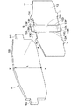
ここで、図1ないし図6は本発明の第1の実施の形態を示している。図中、1は車両の固定部(例えば、後述の取付部材2)に対して回転可能なディスクで、該ディスク1は、車輪(図示せず)と共に回転するものである。   Here, FIG. 1 to FIG. 6 show a first embodiment of the present invention. In the figure, reference numeral 1 denotes a disk that can rotate with respect to a fixed portion (for example, a mounting member 2 described later) of the vehicle. The disk 1 rotates with wheels (not shown).

キャリアと呼ばれる取付部材2は、ディスク1の近傍に位置して車両の非回転部分に取付けられるものである。この取付部材2は、ディスク1の回転方向(本出願においてはディスク周方向という)に離間してディスク1の外周を跨ぐようにディスク1の軸方向(図1の左,右方向、本出願においてはディスク軸方向という)に延びた一対の腕部(図示せず)と、該各腕部の基端側を一体化するように連結して設けられ、ディスク1のインナ側となる位置で車両の非回転部分に固定される厚肉の支承部2Aと、ディスク1のアウタ側で各腕部の先端側を互いに連結し、ディスク周方向に延びる補強ビーム2Bとにより大略構成されている。   An attachment member 2 called a carrier is located near the disk 1 and attached to a non-rotating portion of the vehicle. The attachment member 2 is separated in the rotational direction of the disk 1 (referred to as the disk circumferential direction in the present application) and extends across the outer periphery of the disk 1 in the axial direction of the disk 1 (left and right directions in FIG. And a pair of arm portions (not shown) extending in the disk axial direction) and a base end side of each arm portion are connected so as to be integrated, and the vehicle is positioned at the inner side of the disc 1. The thick support portion 2A fixed to the non-rotating portion of the disc 1 and the reinforcing beam 2B extending in the circumferential direction of the disc are connected to each other on the outer side of the disc 1 and the distal ends of the arms are connected to each other.

ここで、各腕部は、摺動ピン(図示せず)を介して後述のキャリパ3をディスク軸方向に摺動可能に支持している。また、取付部材2のインナ側には、後述するインナ側の摩擦パッド5をディスク軸方向に案内する一対のパッドガイド(図示せず)が設けられている。これら各パッドガイドは、ディスク軸方向に延びる断面コ字形状(断面略U字形状)の凹溝として形成され、摩擦パッド5を挟んでディスク1のディスク周方向一側,他側に離間している。そして、各パッドガイドには、摩擦パッド5の各耳部5C,5Dが例えばパッドスプリング(図示せず)を介してそれぞれ嵌合される。   Here, each arm portion supports a caliper 3 described later via a sliding pin (not shown) so as to be slidable in the disk axial direction. A pair of pad guides (not shown) are provided on the inner side of the mounting member 2 to guide an inner friction pad 5 to be described later in the disk axial direction. Each of these pad guides is formed as a concave groove having a U-shaped cross section (substantially U-shaped cross section) extending in the disk axial direction, and is spaced apart from one side of the disk 1 in the disk circumferential direction and the other side of the friction pad 5. Yes. And each ear | edge part 5C, 5D of the friction pad 5 is each fitted by each pad guide via a pad spring (not shown), for example.

また、取付部材2のアウタ側にも、後述するアウタ側の摩擦パッド6をディスク軸方向に案内する一対のパッドガイド(図示せず)が設けられている。これら各パッドガイドも、インナ側のパッドガイドと同様に、ディスク軸方向に延びる断面コ字形状(断面略U字形状)の凹溝として形成され、摩擦パッド6を挟んでディスク1のディスク周方向一側,他側に離間している。そして、これら各パッドガイドには、摩擦パッド6の各耳部6C,6D(例えば、後述する図11および図12参照)が例えばパッドスプリング(図示せず)を介してそれぞれ嵌合される。   A pair of pad guides (not shown) for guiding an outer friction pad 6 (described later) in the disk axial direction are also provided on the outer side of the mounting member 2. Each of these pad guides is also formed as a groove having a U-shaped cross section (substantially U-shaped cross section) extending in the disk axial direction, like the inner side pad guide, and the disk 1 in the disk circumferential direction of the disk 1 with the friction pad 6 interposed therebetween. Separated from one side to the other. Each of the pad guides is fitted with ears 6C and 6D (for example, see FIGS. 11 and 12 described later) of the friction pad 6 via, for example, pad springs (not shown).

取付部材2には、キャリパ3がディスク軸方向に摺動可能に設けられている。このキャリパ3は、ディスク1の外周側をディスク軸方向に跨いで配置されたもので、ディスク1のインナ側に設けられたインナ脚部3Aと、取付部材2の各腕部間でディスク1の外周側を跨ぐようにインナ脚部3Aからディスク1のアウタ側へと延設されたブリッジ部3Bと、該ブリッジ部3Bの先端側であるアウタ側からディスク1の径方向(本出願においてはディスク径方向という)内向きに延び、先端側が二又状の爪部となったアウタ脚部3Cとにより構成されている。   A caliper 3 is provided on the mounting member 2 so as to be slidable in the disk axial direction. The caliper 3 is disposed so as to straddle the outer peripheral side of the disc 1 in the disc axial direction, and between the inner leg portion 3A provided on the inner side of the disc 1 and each arm portion of the mounting member 2, the disc 1 A bridge portion 3B extending from the inner leg portion 3A to the outer side of the disc 1 so as to straddle the outer peripheral side, and the radial direction of the disc 1 from the outer side which is the tip side of the bridge portion 3B (in the present application, the disc The outer leg 3 </ b> C extends inward (referred to as a radial direction) and has a bifurcated claw at the tip side.

キャリパ3のインナ脚部3Aには、ブレーキ操作時に外部からブレーキ液圧が供給されるシリンダ3Dが設けられ、該シリンダ3D内には後述のピストン4が摺動可能に挿嵌されている。また、インナ脚部3Aには、ディスク周方向に突出して一対のピン取付部(図示せず)が一体に設けられている。これら各ピン取付部は、キャリパ3全体を摺動ピンを介して取付部材2の各腕部に摺動可能に支持させるものである。   The inner leg portion 3A of the caliper 3 is provided with a cylinder 3D to which brake fluid pressure is supplied from the outside during a brake operation, and a piston 4 (described later) is slidably inserted into the cylinder 3D. Further, the inner leg portion 3A is integrally provided with a pair of pin mounting portions (not shown) protruding in the circumferential direction of the disc. Each of these pin mounting portions supports the entire caliper 3 slidably on each arm portion of the mounting member 2 via a sliding pin.

キャリパ3のアウタ脚部3Cは、後述するアウタ側の摩擦パッド6にシム板15を介して当接している。そして、アウタ脚部3Cは、ブレーキ操作時にピストン4との間でインナ側,アウタ側の摩擦パッド5,6をディスク1の両面に向けて押圧するものである。   The outer leg 3 </ b> C of the caliper 3 is in contact with an outer friction pad 6, which will be described later, via a shim plate 15. The outer leg portion 3 </ b> C presses the inner and outer friction pads 5, 6 toward both surfaces of the disk 1 between the piston 4 and the piston 4 during a brake operation.

キャリパ3のディスク軸方向一側であるインナ脚部3Aには、ピストン4が設けられている。該ピストン4は、有底筒状体として形成され、インナ脚部3Aのシリンダ3D内に摺動可能に挿嵌されている。このピストン4は、インナ脚部3Aのシリンダ3D内に外部からブレーキ液圧が供給されると、このときの液圧力でディスク1側に向けてディスク軸方向に摺動変位され、後述するインナ側の摩擦パッド5をディスク1の一側面に押圧するものである。   A piston 4 is provided on the inner leg 3 </ b> A that is one side of the caliper 3 in the disk axial direction. The piston 4 is formed as a bottomed cylindrical body, and is slidably inserted into the cylinder 3D of the inner leg 3A. When the brake fluid pressure is supplied from the outside into the cylinder 3D of the inner leg portion 3A, the piston 4 is slid and displaced in the disc axial direction toward the disc 1 by the fluid pressure at this time. The friction pad 5 is pressed against one side surface of the disk 1.

この場合、ピストン4は、その開口端(先端)がインナ側の摩擦パッド5に後述のシム板11を介して当接している。そして、車両のブレーキ作動時には、ピストン4の開口端側がシム板11に当接した状態で摩擦パッド5をディクス1の表面に向けて押圧するものである。   In this case, the opening end (tip) of the piston 4 is in contact with the inner friction pad 5 via a shim plate 11 described later. When the vehicle is braked, the friction pad 5 is pressed toward the surface of the disk 1 with the opening end side of the piston 4 in contact with the shim plate 11.

ディスク1のディスク軸方向両側面に対向して配置されたインナ側,アウタ側の摩擦パッド5,6は、ディスク1のディスク周方向に延びる板状体として形成されている。これら一対の摩擦パッド5,6は、ピストン4によりディスク1の両面(軸方向両側面)に押圧されるものである。   Inner and outer friction pads 5 and 6 disposed opposite to both sides of the disk 1 in the disk axial direction are formed as plate-like bodies extending in the disk circumferential direction of the disk 1. The pair of friction pads 5 and 6 are pressed against both surfaces (both sides in the axial direction) of the disk 1 by the piston 4.

インナ側の摩擦パッド5は、ディスク1の表面(軸方向側面)に摩擦接触する摩擦材としてのライニング5Aと、該ライニング5Aの裏面側に固着(接合)された裏板5Bとによって構成されている。ここで、裏板5Bは、例えば金属や合成樹脂等により成形され、該裏板5Bには、図2および図3に示すように、ディスク周方向に離間してそれぞれ凸形状をなした耳部5C,5Dが設けられている。   The inner friction pad 5 is composed of a lining 5A as a friction material that is in frictional contact with the surface (axial side surface) of the disk 1, and a back plate 5B fixed (joined) to the back side of the lining 5A. Yes. Here, the back plate 5B is formed of, for example, metal, synthetic resin, or the like, and the back plate 5B is separated from each other in the circumferential direction of the disk as shown in FIGS. 5C and 5D are provided.

これら各耳部5C,5Dは、パッドスプリング(図示せず)を介して取付部材2のインナ側の各パッドガイドにそれぞれ嵌合され、これらパッドガイドとパッドスプリングとによってディスク軸方向に摺動可能に支持されている。そして、各耳部5C,5Dは、車両のブレーキ作動時にディスク1から摩擦パッド5が受ける制動トルクを、取付部材2のパッドガイドと当接して伝達するものである。   These ears 5C and 5D are respectively fitted into pad guides on the inner side of the mounting member 2 via pad springs (not shown), and can be slid in the disk axial direction by these pad guides and pad springs. It is supported by. The ears 5C and 5D transmit the braking torque received by the friction pad 5 from the disk 1 when the vehicle is braked in contact with the pad guide of the mounting member 2.

一方、アウタ側の摩擦パッド6は、インナ側と同様に、ライニング6Aと裏板6Bとによって構成され、裏板6Bの両側にはそれぞれ凸形状をなした耳部6C,6D(例えば、後述する図11および図12参照)が設けられている。これら各耳部6C,6Dは、インナ側と同様に、パッドスプリングを介して取付部材2のアウタ側の各パッドガイドにそれぞれ嵌合され、これらパッドガイドとパッドスプリングとによってディスク軸方向に摺動可能に支持されている。そして、アウタ側の摩擦パッド6の各耳部6C,6Dも、車両のブレーキ作動時にディスク1から摩擦パッド6が受ける制動トルクを、取付部材2のパッドガイドと当接して伝達するものである。   On the other hand, the friction pad 6 on the outer side is composed of a lining 6A and a back plate 6B, as in the inner side, and ears 6C and 6D having convex shapes on both sides of the back plate 6B (for example, described later). 11 and 12) are provided. Each of these ears 6C and 6D is fitted to each pad guide on the outer side of the mounting member 2 via a pad spring, similarly to the inner side, and slides in the disk axial direction by these pad guide and pad spring. Supported as possible. The ears 6C and 6D of the outer friction pad 6 also transmit the braking torque received by the friction pad 6 from the disc 1 when the vehicle is braked, in contact with the pad guide of the mounting member 2.

次に、インナ側の摩擦パッド5とピストン4との間に設けられたインナ側のシム板11について説明する。   Next, the inner shim plate 11 provided between the inner friction pad 5 and the piston 4 will be described.

このインナ側のシム板11は、キャリパ3のインナ脚部3Aに挿嵌されたピストン4とインナ側の摩擦パッド5の裏板5Bとの間に配置され、これらピストン4と摩擦パッド5との間でブレーキ鳴きを防止するものである。このシム板11は、例えば裏板5Bよりも薄い肉厚でばね性を有するステンレス鋼板等をプレス加工することによって一体物として形成され、図2に示すように、インナ側の摩擦パッド5(裏板5B)の背面側(ピストン4側)に、着脱可能に取付けられている。   The inner shim plate 11 is disposed between the piston 4 inserted into the inner leg 3 A of the caliper 3 and the back plate 5 B of the inner friction pad 5. This is to prevent the brake squeaking between. The shim plate 11 is formed as a single body by pressing a stainless steel plate having a thickness smaller than that of the back plate 5B and having spring properties, for example, and as shown in FIG. The plate 5B) is detachably attached to the back side (piston 4 side).

ここで、シム板11は、後述のベース板部12と、取付爪部14とにより大略構成されている。このうちのベース板部12は、摩擦パッド5(裏板5B)の背面に沿ってディスク周方向とディスク径方向とに延びると共にディスク周方向中央部12Aがディスク径方向外側とディスク径方向内側とにそれぞれ突出した、全体として略長方形ないし略扇形状の板状部材として形成されている。そして、ベース板部12のディスク周方向中央部12A(ディスク周方向に関する中央部12A)には、ディスク径方向に延びるように押圧部13が設けられている。   Here, the shim plate 11 is roughly constituted by a base plate portion 12 and a mounting claw portion 14 which will be described later. Of these, the base plate portion 12 extends in the disc circumferential direction and the disc radial direction along the back surface of the friction pad 5 (back plate 5B), and the disc circumferential center portion 12A has a disc radial outside and a disc radial inside. Are formed as plate-shaped members that are substantially rectangular or fan-shaped as a whole. A pressing portion 13 is provided at the disk circumferential direction central portion 12A of the base plate portion 12 (a central portion 12A with respect to the disk circumferential direction) so as to extend in the disk radial direction.

この押圧部13は、シム板11(ベース板部12)のディスク周方向中央部12Aに該シム板11と一体に設けられている。この押圧部13は、摩擦パッド5をシム板11と共に取付部材2に取付けた状態で、ピストン4と摩擦パッド5との間に位置するものである。   The pressing portion 13 is provided integrally with the shim plate 11 at the central portion 12A in the disk circumferential direction of the shim plate 11 (base plate portion 12). The pressing portion 13 is located between the piston 4 and the friction pad 5 in a state where the friction pad 5 is attached to the attachment member 2 together with the shim plate 11.

ここで、押圧部13は、シム板11のディスク周方向中央部12Aをディスク径方向に沿って切起こすことにより形成されている。具体的には、押圧部13は、ディスク径方向に離間して設けられた1対の切起部13Aと、これら両切起部13Aの間に位置してこれら切起部13Aの間を連結する連結部13Bとにより構成されている。   Here, the pressing portion 13 is formed by raising the disc circumferential center portion 12A of the shim plate 11 along the disc radial direction. Specifically, the pressing portion 13 is positioned between a pair of cut and raised portions 13A that are separated from each other in the disk radial direction, and the cut and raised portions 13A are connected to each other. It is comprised by the connection part 13B to perform.

このために、シム板11(ベース板部12)のディスク周方向中央部12Aでディスク径方向に沿った線分X−Xを挟む両側位置には、シム板11の径方向中央を残してディスク径方向に沿うように切込み13C、13Dが形成されている。即ち、シム板11の周方向中央部12Aでディスク径方向外側の端縁には、線分X−Xを挟んで互いに平行に一対の切込み13Cが、ディスク径方向内側に向けて形成されている。これと共に、シム板11のディスク周方向中央部12Aでディスク径方向内側の端縁には、線分X−Xを挟んで互いに平行に一対の切込み13Dが、ディスク径方向外側に向けて形成されている。   For this reason, the disc is left leaving the center in the radial direction of the shim plate 11 at both side positions sandwiching the line segment XX along the disc radial direction in the disc circumferential direction central portion 12A of the shim plate 11 (base plate portion 12). Cuts 13C and 13D are formed along the radial direction. That is, a pair of incisions 13C are formed in the circumferentially central portion 12A of the shim plate 11 on the outer side in the disk radial direction so as to be parallel to each other with the line segment XX inward. . At the same time, a pair of cuts 13D are formed on the inner edge of the shim plate 11 in the circumferential direction of the disk 12A in the disk radial direction so as to be parallel to each other across the line XX. ing.

そして、各切込み13Cにより挟まれた部位が、それぞれ切起部13Aとなり、これら各切起部13Aの先端側には、それぞれピストン4側に向けて折曲げる(起こす)ことにより形成された突出部13Eが設けられている。これら各突出部13Eは、ピストン4の開口端(先端)全体がシム板11と当接するのに先立って、ピストン4の開口端によって押圧される部位となるものである。なお、図2に示すように、切起部13Aの幅寸法W1(各切込み13C,13Dの離間寸法W1)は、ディスク1の周方向に関するシム板11の幅寸法W2の1/2以下(好ましくは1/5以下、さらに好ましくは1/12以上1/7以下)に設定している(W1≦W2/2)。   And the part pinched | interposed by each notch | incision 13C becomes the cut-and-raised part 13A, respectively, The protrusion part formed by bending (raising) toward the piston 4 side at the front end side of each of these cut-and-raised parts 13A, respectively 13E is provided. Each of the protrusions 13 </ b> E serves as a portion that is pressed by the opening end of the piston 4 before the entire opening end (tip) of the piston 4 comes into contact with the shim plate 11. As shown in FIG. 2, the width dimension W1 of the cut-and-raised portion 13A (the separation dimension W1 between the notches 13C and 13D) is ½ or less of the width dimension W2 of the shim plate 11 in the circumferential direction of the disk 1 (preferably Is set to 1/5 or less, more preferably from 1/12 to 1/7 (W1 ≦ W2 / 2).

押圧部13は、ピストン4が摩擦パッド5を押圧し始めたとき、即ち、ディスク1に摩擦パッド5,6が当たり始める程度、例えば、ブレーキペダルに少し足を載せた程度の微圧領域の制動時、より具体的には、例えばピストン4の押圧力Fが、微圧領域、例えば、液圧0.8MPa以下、より好ましくは、液圧0.5MPa以下となる領域において、摩擦パッド5のディスク周方向中央を押圧するものである。   When the piston 4 starts to press the friction pad 5, that is, when the friction pads 5 and 6 start to hit the disk 1, for example, a brake in a small pressure region such that a little foot is placed on the brake pedal. More specifically, for example, in the region where the pressing force F of the piston 4 is in a very low pressure region, for example, a hydraulic pressure of 0.8 MPa or less, more preferably, a hydraulic pressure of 0.5 MPa or less, the disk of the friction pad 5 is used. The center in the circumferential direction is pressed.

即ち、図5に示すように、ピストン4の押圧力Fが微圧領域のときは、切起部13Aの各突出部13Eのみがピストン4の開口端によって押圧される。このとき、切起部13Aのうち各突出部13Eよりも基端側の部位となる裏板当接部13Fと該裏板当接部13Fの間の連結部13Bとが、摩擦パッド5の周方向中央でディスク径方向に沿った線分X−X上を一定の長さをもって押圧する。この押圧部13全体が本願発明のピストンが摩擦パッドを押圧し始めたとき、ピストンのディスク周方向中央で該摩擦パッドを押圧する押圧機構を構成する。   That is, as shown in FIG. 5, when the pressing force F of the piston 4 is in the slight pressure region, only the protruding portions 13 </ b> E of the cut and raised portion 13 </ b> A are pressed by the opening end of the piston 4. At this time, the back plate contact portion 13F, which is the base end side of each protruding portion 13E in the cut and raised portion 13A, and the connecting portion 13B between the back plate contact portions 13F are arranged around the friction pad 5. A certain length is pressed on the line XX along the disk radial direction at the center in the direction. The entire pressing portion 13 constitutes a pressing mechanism that presses the friction pad at the center in the disk circumferential direction of the piston when the piston of the present invention starts to press the friction pad.

なお、一定の長さとは、例えば裏板5Bのディスク周方向中央のディスク径方向寸法L(図4参照)の1/3以上(好ましくは1/2以上、さらに好ましくは3/4以上)の長さとすることができる。換言すれば、例えば微圧鳴きを安定して抑制することができるように、摩擦パッド5の寸法、必要とされるブレーキ性能等に応じて適切な長さに設定することができる。   The fixed length is, for example, 1/3 or more (preferably 1/2 or more, more preferably 3/4 or more) of the disk radial direction dimension L (see FIG. 4) at the center in the disk circumferential direction of the back plate 5B. It can be a length. In other words, for example, the length can be set to an appropriate length according to the size of the friction pad 5, the required brake performance, and the like so as to be able to stably suppress the fine noise.

ピストン4の押圧力Fが微圧領域のときは、ピストン4の押圧力Fの増大に伴って、突出部13Eが摩擦パッド5に近付く方向に弾性変形する。そして、ピストン4の押圧力Fが微圧領域を超えると、図6に示すように、突出部13Eが摩擦パッド5側に最も撓むことにより(最大撓み状態となることにより)、突出部13Eと裏板当接部13Fおよび連結部13Bとが同一平面となる。このような微圧領域を超えた状態では、ピストン4の開口端のうちシム板11とディスク1の軸方向に重なる部位の全体がシム板11と当接して該ピストン4全体で摩擦パッド5を押圧する。   When the pressing force F of the piston 4 is in the low pressure region, the protrusion 13E is elastically deformed in a direction approaching the friction pad 5 as the pressing force F of the piston 4 increases. Then, when the pressing force F of the piston 4 exceeds the minute pressure region, as shown in FIG. 6, the protrusion 13E is most bent toward the friction pad 5 side (by being in a maximum bending state), thereby causing the protrusion 13E. The back plate contact portion 13F and the connecting portion 13B are flush with each other. In such a state where the fine pressure region is exceeded, the entire portion of the opening end of the piston 4 that overlaps the shim plate 11 and the disk 1 in the axial direction is in contact with the shim plate 11 so that the friction pad 5 is entirely covered by the piston 4. Press.

その結果、ピストン4の押圧力Fが微圧領域のときは、ピストン4のディスク周方向の中央において、押圧部13(押圧機構)によって、摩擦パッド5に力を伝達するが、微圧領域を超えたときは、摩擦パッド5に力を伝達するディスク周方向の範囲が、ピストン4のディスク周方向の両端Tまで延び、ディスク周方向全体で前記摩擦パッド5に力を伝達することになる。   As a result, when the pressing force F of the piston 4 is in the low pressure region, force is transmitted to the friction pad 5 by the pressing portion 13 (pressing mechanism) in the center of the piston 4 in the disk circumferential direction. When exceeding, the range in the disk circumferential direction for transmitting the force to the friction pad 5 extends to both ends T of the piston 4 in the disk circumferential direction, and the force is transmitted to the friction pad 5 in the entire disk circumferential direction.

これにより、ピストン4の押圧力Fが微圧領域においては、該ピストン4の押圧力Fを、押圧部(押圧機構)13を介してディスク周方向の中央において摩擦パッド5に伝達するが、微圧領域を超えてからは、摩擦パッド5に力を伝達するディスク周方向の範囲が、ピストン4のディスク周方向の両端Tまで延び、ピストン4の押圧力Fを該ピストン4のディスク周方向全体(ピストン4の開口端のうちシム板11とディスク1の軸方向に重なる部位の全体)で摩擦パッド5に伝達できるように構成している。   As a result, when the pressing force F of the piston 4 is in the low pressure region, the pressing force F of the piston 4 is transmitted to the friction pad 5 through the pressing portion (pressing mechanism) 13 at the center in the disk circumferential direction. After exceeding the pressure region, the disk circumferential direction range for transmitting the force to the friction pad 5 extends to both ends T of the piston 4 in the disk circumferential direction, and the pressing force F of the piston 4 is applied to the entire disk circumferential direction of the piston 4. (The entire portion of the opening end of the piston 4 that overlaps the shim plate 11 and the disk 1 in the axial direction) can be transmitted to the friction pad 5.

ピストン4の押圧力Fが微圧領域においては、摩擦パッド5のディスク周方向中央でディスク径方向に沿った線分X−X上が、押圧部13によって押圧される。ここで、線分X−Xは、微圧領域の制動時のブレーキ鳴き、所謂、微圧鳴き特有の振動モードである摩擦パッド5の軸方向の一次曲げモーメントの節に対応する。そして、微圧領域では、摩擦パッド5のうち当該節に対応する線分X−X上の部位が、押圧部13を介して押圧される。換言すれば、ピストン4の押圧力Fが、摩擦パッド5の振動の節となる線分X−X上の部位のみを介して、摩擦パッド5に伝達される。このため、微圧領域の制動時に、摩擦パッド5の振動がピストン4を介してキャリパ3側に伝達されることを低減することができ、微圧鳴きを安定して抑制することができる。   When the pressing force F of the piston 4 is in the low pressure region, the pressing portion 13 presses the line segment XX along the disk radial direction at the center of the friction pad 5 in the disk circumferential direction. Here, the line segment X-X corresponds to a node of the primary bending moment in the axial direction of the friction pad 5 which is a vibration mode peculiar to the low pressure squealing, that is, a brake squeal at the time of braking in the low pressure region. In the fine pressure region, the portion of the friction pad 5 on the line segment XX corresponding to the node is pressed via the pressing portion 13. In other words, the pressing force F of the piston 4 is transmitted to the friction pad 5 only through the portion on the line segment XX that becomes the vibration node of the friction pad 5. For this reason, it is possible to reduce the vibration of the friction pad 5 transmitted to the caliper 3 side via the piston 4 during braking in the low pressure region, and to suppress the low pressure noise stably.

シム板11(ベース板部12)の周縁部の4箇所位置には、該周縁部から突出するように取付爪部14が設けられている。これら取付爪部14は、シム板11を摩擦パッド5の裏板5Bに対して取付けるためのものである。なお、本実施の形態においては、取付爪部14をディスク径方向外側および径方向内側にそれぞれ2個づつ合計4個設けているが、これに限らず、例えばディスク径方向外側および径方向内側にそれぞれ1個以上設けられていれば、2個以上で構成してもよい。   At four positions on the periphery of the shim plate 11 (base plate portion 12), mounting claws 14 are provided so as to protrude from the periphery. These attachment claws 14 are for attaching the shim plate 11 to the back plate 5B of the friction pad 5. In the present embodiment, a total of four mounting claws 14 are provided, two on each of the outer side and the inner side in the radial direction of the disk. However, the present invention is not limited to this. If one or more of each is provided, it may be composed of two or more.

次に、アウタ側の摩擦パッド6とキャリパ3のアウタ脚部3Cとの間に設けたアウタ側のシム板15(図1参照)について説明する。   Next, the outer shim plate 15 (see FIG. 1) provided between the outer friction pad 6 and the outer leg 3C of the caliper 3 will be described.

このアウタ側のシム板15は、キャリパ3のアウタ脚部3Cとインナ側の摩擦パッド6の裏板6Bとの間に配置され、これらアウタ脚部3Cと摩擦パッド6との間でブレーキ鳴きを防止するものである。このシム板15は、例えば裏板6Bよりも薄い肉厚でばね性を有するステンレス鋼板等をプレス加工することによって一体物として形成され、アウタ側の摩擦パッド6(裏板6B)の背面側(ライニング6Aとは反対側)に着脱可能に取付けられている。   The outer side shim plate 15 is disposed between the outer leg portion 3C of the caliper 3 and the back plate 6B of the inner friction pad 6. The brake squeal is generated between the outer leg portion 3C and the friction pad 6. It is to prevent. The shim plate 15 is formed as a single body by, for example, pressing a stainless steel plate having a thickness smaller than that of the back plate 6B and having spring properties, and the back side of the outer friction pad 6 (back plate 6B) ( It is detachably attached to the side opposite to the lining 6A.

ここで、アウタ側のシム板15は、摩擦パッド6(裏板6B)の背面に沿ってディスク周方向と径方向とに延びる略長方形ないし略扇形状の平板として形成されたものである。本実施の形態の場合は、アウタ側のシム板15には、上述したインナ側のシム板11で設けられていたような押圧部13は設けていない。   Here, the outer side shim plate 15 is formed as a substantially rectangular or substantially fan-shaped flat plate extending in the disk circumferential direction and the radial direction along the back surface of the friction pad 6 (back plate 6B). In the case of this embodiment, the outer shim plate 15 is not provided with the pressing portion 13 which is provided by the inner shim plate 11 described above.

このようなアウタ側のシム板15は、キャリパ3のアウタ脚部3Cとインナ側の摩擦パッド6の裏板6Bとが直に接触することを防止することにより、両者の間でブレーキ鳴きの発生を抑えるものである。なお、アウタ側のシム板15は、後述する他の実施の形態(例えば第3の実施の形態等)のように、押圧部が設けられたシム板にすることもできる。   Such an outer side shim plate 15 prevents a brake squeal between the outer leg 3C of the caliper 3 and the back plate 6B of the inner friction pad 6 by preventing direct contact with each other. It is what suppresses. The outer side shim plate 15 can also be a shim plate provided with a pressing portion, as in other embodiments described later (for example, the third embodiment).

本実施の形態によるディスクブレーキは、上述の如き構成を有するもので、次にその作動について説明する。   The disc brake according to the present embodiment has the above-described configuration, and the operation thereof will be described next.

まず、車両のブレーキ操作時には、キャリパ3のシリンダ3Dにブレーキ液圧を供給することによりピストン4をディスク1に向けて摺動変位させ、これによりインナ側の摩擦パッド5をディスク1の一側面に押圧する。そして、このときにはキャリパ3がディスク1からの押圧反力を受けるため、キャリパ3全体が取付部材2の腕部に対してインナ側に摺動変位し、アウタ脚部3Cがアウタ側の摩擦パッド6をディスク1の他側面に押圧する。   First, at the time of brake operation of the vehicle, the brake fluid pressure is supplied to the cylinder 3D of the caliper 3 to displace the piston 4 toward the disk 1 so that the inner friction pad 5 is placed on one side of the disk 1. Press. At this time, since the caliper 3 receives a pressing reaction force from the disk 1, the entire caliper 3 is slid and displaced toward the inner side with respect to the arm portion of the mounting member 2, and the outer leg portion 3C is the friction pad 6 on the outer side. Is pressed against the other side of the disk 1.

これにより、インナ側とアウタ側の摩擦パッド5,6は、車輪と共に回転しているディスク1を、両者の間でディスク軸方向両側から強く挟持することができ、このディスク1に制動力を与えることができる。そして、ブレーキ操作を解除したときには、ピストン4への液圧供給が停止されることにより、インナ側とアウタ側の摩擦パッド5,6がディスク1から離間し、再び非制動状態に復帰する。   Thereby, the friction pads 5 and 6 on the inner side and the outer side can strongly hold the disc 1 rotating together with the wheels from both sides in the disc axial direction, and give a braking force to the disc 1. be able to. When the brake operation is released, the hydraulic pressure supply to the piston 4 is stopped, so that the inner and outer friction pads 5 and 6 are separated from the disk 1 and return to the non-braking state again.

このようなブレーキ操作時、ピストン4の押圧力Fが、微圧領域、例えば、液圧0.8MPa以下、より好ましくは液圧0.5MPa以下となる領域であるときは、図5に示すように、インナ側のシム板11の切起部13A(各突出部13E)のみが、ピストン4の開口端によって押圧される。このとき、切起部13Aの裏板当接部13Fと連結部13Bとが、摩擦パッド5のディスク周方向中央でディスク1の径方向に沿った線分X−X上を押圧する。   When the pressing force F of the piston 4 is in a slight pressure region, for example, a fluid pressure of 0.8 MPa or less, more preferably a fluid pressure of 0.5 MPa or less during such a brake operation, as shown in FIG. In addition, only the cut and raised portions 13 </ b> A (each projecting portion 13 </ b> E) of the inner shim plate 11 are pressed by the opening end of the piston 4. At this time, the back plate contact portion 13F and the connecting portion 13B of the cut and raised portion 13A press the line segment XX along the radial direction of the disk 1 at the center of the friction pad 5 in the disk circumferential direction.

この線分X−Xは、微圧鳴き特有の振動モードである摩擦パッド5の軸方向の一次曲げモーメントの節に対応し、微圧領域では、摩擦パッド5のうち当該節に対応する線分X−X上の部位が押圧部13を介して押圧される。このため、微圧領域の制動時に、摩擦パッド5の振動が、ピストン4を介してキャリパ3側に伝達されることを低減することができ、微圧鳴きを安定して抑制することができる。   This line segment XX corresponds to a node of the primary bending moment in the axial direction of the friction pad 5 which is a vibration mode peculiar to the fine pressure squeal, and in the fine pressure region, the line segment corresponding to the node of the friction pad 5. The part on XX is pressed via the pressing part 13. For this reason, it is possible to reduce the vibration of the friction pad 5 transmitted to the caliper 3 side via the piston 4 during braking in the low pressure region, and to suppress the low pressure noise stably.

一方、ピストン4の押圧力Fが微圧領域を超えると、図6に示すように、切起部13Aの突出部13Eが摩擦パッド5側に最も撓むことにより、突出部13Eと裏板当接部13Fおよび連結部13Bとが同一平面となる。このような微圧領域を超えた状態では、ピストン4の開口端全体(開口端のうちシム板11とディスク軸方向に重なる部位の全体)がシム板11と当接して該ピストン4全体で摩擦パッド5が押圧される。これにより、インナ側とアウタ側の摩擦パッド5,6は、ピストン4の押圧力Fに応じた大きな力(微圧領域を超える力)でディスク1をディスク軸方向両側から挟持することができ、該ディスク1に大きな制動力を与えることができる。   On the other hand, when the pressing force F of the piston 4 exceeds the slight pressure region, as shown in FIG. 6, the protruding portion 13E of the cut and raised portion 13A bends most toward the friction pad 5, thereby causing the protruding portion 13E and the back plate contact. The contact portion 13F and the connecting portion 13B are on the same plane. In such a state where the fine pressure region is exceeded, the entire open end of the piston 4 (the entire portion of the open end that overlaps with the shim plate 11 in the disk axial direction) abuts on the shim plate 11 and the piston 4 as a whole frictions. The pad 5 is pressed. Thereby, the friction pads 5 and 6 on the inner side and the outer side can sandwich the disk 1 from both sides in the disk axial direction with a large force (a force exceeding the fine pressure region) according to the pressing force F of the piston 4. A large braking force can be applied to the disk 1.

ところで、ピストン4の押圧力Fが微圧領域、例えば液圧0.8MPa以下の領域における制動時に、微圧鳴きと呼ばれるブレーキ鳴きが発生する場合がある。このような微圧鳴きは、例えば、シム板にグリースを塗布することにより、或いは、ゴム等の弾性材を積層した積層シム板を用いることにより、その低減を図ることが行われている。ただし、このようにグリースを塗布する構成や積層シム板を用いる場合は、コストが嵩む虞がある。また、グリースや弾性材の経時劣化に伴って、微圧鳴きを十分に抑制できなくなる虞がある。   By the way, there is a case where a brake squeal called a fine pressure squeal occurs during braking in a region where the pressing force F of the piston 4 is a low pressure region, for example, a region where the hydraulic pressure is 0.8 MPa or less. Such fine squeal is reduced by, for example, applying grease to the shim plate or using a laminated shim plate in which an elastic material such as rubber is laminated. However, there is a risk that the cost may increase when the structure for applying grease or the laminated shim plate is used. Moreover, there is a possibility that the fine squeal cannot be sufficiently suppressed with the aging of the grease and the elastic material.

一方、前述の特許文献1には、ピストンをディスク周方向に付勢する付勢手段をキャリパのシリンダ内に設けることにより、微圧鳴きを抑制できるようにした構成が記載されている。ただし、この構成の場合は、例えばキャリパのシリンダ内に付勢手段を組付ける作業が必要になり、その分、コストが増大する虞がある。   On the other hand, the above-described Patent Document 1 describes a configuration in which fine pressure noise can be suppressed by providing a biasing means for biasing the piston in the circumferential direction of the disk in the cylinder of the caliper. However, in the case of this configuration, for example, an operation of assembling the urging means in the caliper cylinder is required, which may increase the cost accordingly.

これに対し、本実施の形態によれば、ピストン4とインナ側の摩擦パッド5との間に、該摩擦パッド5の周方向中央でディスク1の径方向に沿った線分X−X上を一定の長さをもって押圧する押圧部13を設ける構成としている。そして、ピストン4が摩擦パッド5を押圧し始めたときに、押圧部13により、ピストン4の押圧力Fを摩擦パッド5に伝達できるように構成している。   In contrast, according to the present embodiment, between the piston 4 and the friction pad 5 on the inner side, on the line segment XX along the radial direction of the disk 1 at the circumferential center of the friction pad 5. The pressing portion 13 that presses with a certain length is provided. When the piston 4 starts to press the friction pad 5, the pressing force F of the piston 4 can be transmitted to the friction pad 5 by the pressing portion 13.

このため、ピストン4の押圧力Fが微圧領域となる制動時に、摩擦パッド5は、微圧鳴き特有の振動モードである摩擦パッド5の軸方向の一次曲げモーメントの節に対応する線分X−X上の部位が、押圧部13により押圧される。これにより、微圧領域の制動時に、摩擦パッド5の振動が、ピストン4を介してキャリパ3側に伝達されることを低減することができ、微圧鳴きを安定して抑制することができる。   For this reason, at the time of braking in which the pressing force F of the piston 4 is in the fine pressure region, the friction pad 5 has a line segment X corresponding to a node of the primary bending moment in the axial direction of the friction pad 5 which is a vibration mode peculiar to the fine pressure noise. The portion on −X is pressed by the pressing portion 13. Thereby, the vibration of the friction pad 5 can be reduced from being transmitted to the caliper 3 via the piston 4 during braking in the low pressure region, and the low pressure noise can be stably suppressed.

しかも、押圧部13は、グリースやシム板に積層されるゴム等に比べ経時劣化の影響を受けにくくできる、言い換えれば、経時劣化しにくくできるため、長期間の使用に拘わらず微圧鳴きを安定して抑制することができる。さらに、押圧部13は、摩擦パッド5の周方向中央部、例えば、図3,図4に示される線分X−X上を押圧するため、摩擦パッド5のライニング5Aの摩耗状態に拘わらず、摩擦パッド5が新品のときから交換の時期に至るまで、微圧鳴きを安定して抑制することができる。   In addition, the pressing portion 13 can be less susceptible to deterioration over time compared to grease or rubber laminated on a shim plate, in other words, it can be resistant to deterioration over time, so that it can stably maintain a slight squeal regardless of long-term use. And can be suppressed. Furthermore, since the pressing part 13 presses the circumferential center part of the friction pad 5, for example, on the line segment XX shown in FIG. 3, FIG. 4, regardless of the wear state of the lining 5A of the friction pad 5, From the time when the friction pad 5 is new to the time of replacement, it is possible to stably suppress the slight noise.

本実施の形態によれば、押圧部13はインナ側のシム板11に一体に設ける構成としているので、例えば、押圧部13をプレス加工により容易に、しかも、例えばシム板11の形成作業と同時に形成することができる。このため、シム板にグリースを塗布する構成や、積層シム板を用いる構成に比べ、コストを低減することができる。   According to the present embodiment, since the pressing portion 13 is provided integrally with the inner shim plate 11, for example, the pressing portion 13 can be easily formed by pressing and simultaneously with, for example, the forming operation of the shim plate 11. Can be formed. For this reason, cost can be reduced compared with the structure which apply | coats grease to a shim board, or the structure which uses a lamination shim board.

本実施の形態によれば、押圧部13は、シム板11のディスク周方向中央部12Aをディスク径方向に沿って切起こすことにより形成しているので、押圧部13をプレス加工等の簡素な加工工程で形成することができる。このため、この面からも、コストを低減することができる。   According to the present embodiment, the pressing portion 13 is formed by cutting and raising the disc circumferential direction central portion 12A of the shim plate 11 along the disc radial direction. It can be formed by a processing step. For this reason, cost can be reduced also from this aspect.

本実施の形態によれば、押圧部13の切起部13Aの幅寸法W1をディスク周方向に関するシム板11の幅寸法W2の1/2以下に設定しているので、押圧部13により摩擦パッド5のディスク周方向中央部の線分X−X上を一定の面積をもって押圧することができる。このため、この面からも、微圧鳴きを安定して抑制することができる。   According to the present embodiment, the width dimension W1 of the cut-and-raised portion 13A of the pressing portion 13 is set to ½ or less of the width dimension W2 of the shim plate 11 in the disk circumferential direction. 5 can be pressed with a certain area on the line segment XX at the center in the circumferential direction of the disk. For this reason, it is possible to stably suppress the slight noise from this aspect.

本実施の形態によれば、ピストン4の押圧力Fが、微圧領域、例えば、液圧0.8MPa以下、より好ましくは、0.5MPa以下となる領域において、該ピストン4の押圧力Fが押圧部13(のみ)を介して摩擦パッド5に伝達される構成としているので、ディスク1に摩擦パッド5,6が当たり始める程度、即ち、ブレーキペダルに少し足を載せた程度の微圧領域の制動時における微圧鳴きを安定して抑制することができる。   According to the present embodiment, in the region where the pressing force F of the piston 4 is in a fine pressure region, for example, the hydraulic pressure of 0.8 MPa or less, more preferably 0.5 MPa or less, the pressing force F of the piston 4 is Since it is configured to be transmitted to the friction pad 5 via the pressing portion 13 (only), a slight pressure region such that the friction pads 5 and 6 start to hit the disk 1, that is, a little foot is placed on the brake pedal. Slight squealing during braking can be stably suppressed.

次に、図7および図8は本発明の第2の実施の形態を示している。本実施の形態の特徴は、押圧部を構成する切起部の先端側に摩擦パッドの裏板と弾性的に接触する弾性接触部を設ける構成としたことにある。なお、本実施の形態では、上述した第1の実施の形態と同一の構成要素に同一の符号を付し、その説明を省略するものとする。   Next, FIG. 7 and FIG. 8 show a second embodiment of the present invention. A feature of the present embodiment is that an elastic contact portion that elastically contacts the back plate of the friction pad is provided on the front end side of the cut and raised portion that constitutes the pressing portion. In the present embodiment, the same components as those in the first embodiment described above are denoted by the same reference numerals, and the description thereof is omitted.

シム板11(ベース板部12)のディスク周方向中央部12Aに位置して該シム板11と一体に設けられた押圧部13は、ディスク径方向に離間して設けられた1対の切起部13Aと、これら両切起部13Aの間に位置してこれら切起部13Aの間を連結する連結部13Bとにより大略構成されている。そして、各切起部13Aの先端側には、ピストン4側に向けて折曲げる(起こす)ことにより形成された突出部13Eと、該突出部13Eの先端側から摩擦パッド5の裏板5Bの周縁部に向けて断面略S字状に折返すことにより形成された弾性接触部としての折返し部21とが設けられている。ここで、折返し部21の先端側は、裏板5Bの周縁部に弾性的に接触(係合)し、これにより、例えば突出部13Eのばね定数(弾性力)を大きくできるように構成している。   The pressing portion 13 provided integrally with the shim plate 11 at the disc circumferential direction central portion 12A of the shim plate 11 (base plate portion 12) is a pair of cut and raised portions provided separately from each other in the disc radial direction. It is roughly configured by a portion 13A and a connecting portion 13B that is located between both the cut and raised portions 13A and connects the cut and raised portions 13A. And at the front end side of each cut-and-raised part 13A, the protruding part 13E formed by bending (raising) toward the piston 4 side, and the back plate 5B of the friction pad 5 from the front end side of the protruding part 13E A folded portion 21 is provided as an elastic contact portion that is formed by folding the peripheral portion into a substantially S-shaped cross section. Here, the front end side of the folded-back portion 21 is configured to be elastically contacted (engaged) with the peripheral portion of the back plate 5B so that, for example, the spring constant (elastic force) of the protruding portion 13E can be increased. Yes.

本実施の形態によるディスクブレーキは、上述の如きシム板11を用いてブレーキ鳴きを防止するもので、その基本的作用については、上述した第1の実施の形態によるものと格別差異はない。   The disc brake according to the present embodiment uses the shim plate 11 as described above to prevent brake squeal, and the basic action is not different from that according to the first embodiment described above.

特に、本実施の形態では、突出部13Eの先端側に裏板5Bの周縁部と弾性的に接触する折返し部21を設ける構成としているので、該折返し部21により、突出部13Eのばね定数を大きくすることができる。また、折返し部21により、突出部13Eのばね定数を微細に設定することもできる。これにより、微圧領域の制動時に、ピストン4から押圧部13を介して摩擦パッド5に加わる押圧力Fの安定化を図ることができ、微圧鳴きをより一層安定して抑制することができる。   In particular, in the present embodiment, the folded portion 21 that elastically contacts the peripheral edge of the back plate 5B is provided on the distal end side of the protruding portion 13E, and therefore the spring constant of the protruding portion 13E is set by the folded portion 21. Can be bigger. Moreover, the spring constant of the protrusion part 13E can also be set finely by the folding | turning part 21. FIG. Thereby, it is possible to stabilize the pressing force F applied to the friction pad 5 from the piston 4 via the pressing portion 13 during braking in the low pressure region, and to suppress the fine pressure squeal more stably. .

次に、図9ないし図12は本発明の第3の実施の形態を示している。本実施の形態の特徴は、押圧部を構成する切起部を周方向に切起こすことにより構成すると共に、アウタ側の摩擦パッドとキャリパのアウタ脚部との間にも押圧部を有するシム板を設ける構成としたことにある。なお、本実施の形態では、上述した第1の実施の形態と同一の構成要素に同一の符号を付し、その説明を省略するものとする。   Next, FIGS. 9 to 12 show a third embodiment of the present invention. A feature of the present embodiment is that the shim plate is configured by cutting and raising the cutting-up portion constituting the pressing portion in the circumferential direction and having a pressing portion between the outer friction pad and the outer leg portion of the caliper. It is that it was set as the structure which provides. In the present embodiment, the same components as those in the first embodiment described above are denoted by the same reference numerals, and the description thereof is omitted.

インナ側の摩擦パッド5とピストン4との間に設けられたインナ側のシム板31は、図9および図10に示すように、取付爪部14と、後述のベース板部32とにより大略構成されている。このベース板部32は、インナ側の摩擦パッド5(裏板5B)の背面に沿ってディスク周方向と径方向とに延びる略長方形ないし略扇形状の板状部材として形成されている。そして、ベース板部32には、ディスク周方向に延びるように第1の押圧部33と第2の押圧部34が設けられている。   As shown in FIGS. 9 and 10, the inner shim plate 31 provided between the inner friction pad 5 and the piston 4 is roughly constituted by a mounting claw portion 14 and a base plate portion 32 described later. Has been. The base plate portion 32 is formed as a substantially rectangular or substantially fan-shaped plate-like member extending in the disk circumferential direction and the radial direction along the back surface of the inner friction pad 5 (back plate 5B). The base plate portion 32 is provided with a first pressing portion 33 and a second pressing portion 34 so as to extend in the disk circumferential direction.

これら第1の押圧部33と第2の押圧部34は、ディスク径方向に離間して互いに平行にシム板31(ベース板部32)と一体に設けられている。これら各押圧部33,34は、摩擦パッド5をシム板31と共に取付部材2に取付けた状態で、ピストン4と摩擦パッド5との間に位置するものである。   The first pressing portion 33 and the second pressing portion 34 are provided integrally with the shim plate 31 (base plate portion 32) so as to be spaced apart from each other in the disk radial direction and parallel to each other. Each of the pressing portions 33 and 34 is located between the piston 4 and the friction pad 5 in a state where the friction pad 5 is attached to the attachment member 2 together with the shim plate 31.

ここで、各押圧部33,34は、シム板31を構成するベース板部32のディスク周方向中央部32Aを残してディスク1の周方向に沿って切起こすことにより形成されている。具体的には、各押圧部33,34は、ディスク1の周方向に離間して設けられた1対の切起部33A,34Aと、これら各切起部33A,34Aの間にそれぞれ位置してこれら切起部33A,34Aの間を連結する連結部33B,34Bとにより大略構成されている。   Here, each pressing portion 33, 34 is formed by raising along the circumferential direction of the disk 1, leaving the disk circumferential direction center portion 32 </ b> A of the base plate portion 32 constituting the shim plate 31. Specifically, each of the pressing portions 33 and 34 is positioned between a pair of cut and raised portions 33A and 34A that are separated from each other in the circumferential direction of the disk 1 and the cut and raised portions 33A and 34A. The connecting portions 33B and 34B that connect the cut and raised portions 33A and 34A are roughly configured.

このために、シム板31(ベース板部32)の上部側には、ディスク周方向中央部32Aを残して該中央部32Aからディスク1の周方向に沿うように略U字状(略コ字状)の切込み33C、33Cが、周方向中央部32Aを挟んで互いに対称に形成されている。そして、各切込み33C、33Cにより挟まれた(囲まれた)部位が、それぞれ第1の押圧部33の切起部33Aとなり、これら各切起部33Aは、図10に示すように、それぞれピストン4側に向けて折曲げられている(起こされている)。これにより、各切起部33Aは、シム板31の周方向中央部32Aを残してディスク1の周方向に沿ってピストン4側に切起こすことにより形成されている。   For this reason, the upper side of the shim plate 31 (base plate portion 32) is substantially U-shaped (substantially U-shaped) along the circumferential direction of the disc 1 from the central portion 32A, leaving the disc circumferential central portion 32A. Are formed symmetrically with respect to the circumferential center portion 32A. The portions sandwiched (enclosed) by the respective cuts 33C and 33C become the cut-and-raised portions 33A of the first pressing portions 33, respectively. These cut-and-raised portions 33A are respectively pistons as shown in FIG. It is bent (raised) towards the 4 side. As a result, each cut-and-raised portion 33A is formed by cutting up toward the piston 4 along the circumferential direction of the disk 1 while leaving the circumferential center portion 32A of the shim plate 31.

一方、シム板31(ベース板部32)の下部側には、ディスク周方向中央部32Aを残して該中央部32Aからディスク1の周方向に沿うように略U字状(略コ字状)の切込み34C、34Cが、周方向中央部32Aを挟んで互いに対称に形成されている。そして、各切込み34C、34Cにより挟まれた(囲まれた)部位が、それぞれ第2の押圧部34の切起部34Aとなり、これら各切起部34Aは、図10に示すように、それぞれピストン4側に向けて折曲げられている(起こされている)。これにより、各切起部34Aは、シム板31のディスク周方向中央部32Aを残してディスク1の周方向に沿ってピストン4側に切起こすことにより形成されている。   On the other hand, on the lower side of the shim plate 31 (base plate portion 32), a substantially U-shaped (substantially U-shaped) shape is provided so as to follow the circumferential direction of the disc 1 from the central portion 32A, leaving the disc circumferential central portion 32A. The cuts 34C and 34C are formed symmetrically with respect to the circumferential center portion 32A. Then, the portions sandwiched (enclosed) by the notches 34C and 34C become the cut and raised portions 34A of the second pressing portions 34, respectively. As shown in FIG. It is bent (raised) towards the 4 side. Accordingly, each cut-and-raised portion 34A is formed by cutting and raising the shim plate 31 toward the piston 4 along the circumferential direction of the disc 1 while leaving the central portion 32A in the circumferential direction of the disc.

第1の押圧部33の各切起部33Aと第1の押圧部34の各切起部34Aは、ピストン4の開口端(先端)全体がシム板31と当接するのに先立って、ピストン4の開口端によって押圧される部位となるものである。また、ピストン4の開口端によって各切起部33A,34Aが押圧されると、該ピストン4の押圧力Fは、シム板31のディスク周方向中央部32Aで、各切起部33A,34Aの基端側同士を連結する連結部33B,34Bを介して、摩擦パッド5に伝達される。   Each cut-and-raised portion 33A of the first pressing portion 33 and each cut-and-raised portion 34A of the first pressing portion 34 are arranged in the piston 4 before the entire opening end (tip) of the piston 4 comes into contact with the shim plate 31. It becomes a site | part pressed by the opening end of. In addition, when the cut and raised portions 33A and 34A are pressed by the opening end of the piston 4, the pressing force F of the piston 4 is at the center portion 32A in the disk circumferential direction of the shim plate 31 and the cut and raised portions 33A and 34A. It is transmitted to the friction pad 5 via the connecting portions 33B and 34B that connect the base end sides.

各押圧部33,34は、ピストン4が摩擦パッド5を押圧し始めたとき、より具体的には、ピストン4の押圧力Fが、微圧領域、例えば液圧0.8MPa以下、より好ましくは、液圧0.5MPa以下となる領域において、摩擦パッド5のディスク周方向中央を押圧するものである。即ち、ピストン4の押圧力Fが微圧領域のときは、各切起部33A,34Aのみがピストン4の開口端によって押圧される。このとき、各切起部33A,34Aの間の連結部33B,34Bが、摩擦パッド5の周方向中央でディスク1の径方向に沿った線分X−X上を2箇所位置で押圧する。   When the piston 4 starts to press the friction pad 5, more specifically, each pressing portion 33, 34 has a pressing force F of the piston 4 in a fine pressure region, for example, a hydraulic pressure of 0.8 MPa or less, more preferably In the region where the hydraulic pressure is 0.5 MPa or less, the center of the friction pad 5 in the circumferential direction of the disk is pressed. That is, when the pressing force F of the piston 4 is in the minute pressure region, only the cut and raised portions 33A and 34A are pressed by the opening end of the piston 4. At this time, the connecting portions 33B and 34B between the cut and raised portions 33A and 34A press at two positions on the line segment XX along the radial direction of the disk 1 at the circumferential center of the friction pad 5.

また、ピストン4の押圧力Fが微圧領域のときは、ピストン4の押圧力Fの増大に伴って、各切起部33A,34Aが摩擦パッド5に近付く方向に弾性変形する。そして、ピストン4の押圧力Fが微圧領域を超えると、各切起部33A,34Aが摩擦パッド5側に最も撓むことにより(最大撓み状態となることにより)、各切起部33A,34Aと連結部33B,34Bとが同一平面となる。このような微圧領域を超えた状態では、ピストン4の開口端のうちシム板31とディスク1の軸方向に重なる部位の全体がシム板31と当接して該ピストン4全体で摩擦パッド5が押圧される。   Further, when the pressing force F of the piston 4 is in the minute pressure region, each of the cut and raised portions 33A and 34A is elastically deformed in the direction approaching the friction pad 5 as the pressing force F of the piston 4 increases. When the pressing force F of the piston 4 exceeds the slight pressure region, the cut and raised portions 33A and 34A are most bent toward the friction pad 5 (by being in a maximum bent state), thereby causing the cut and raised portions 33A and 33A, 34A and connection part 33B, 34B become the same plane. In such a state where the fine pressure region is exceeded, the entire portion of the opening end of the piston 4 that overlaps the shim plate 31 and the disk 1 in the axial direction is in contact with the shim plate 31, and the friction pad 5 is formed in the entire piston 4. Pressed.

これにより、ピストン4の押圧力Fが微圧領域においては、該ピストン4の押圧力Fを、第1の押圧部33と第2の押圧部34を介してディスク周方向中央部において摩擦パッド5に伝達し、微圧領域を超えてからは、押圧力Fを及ぼす範囲がディスク周方向に延びて、ピストン4の押圧力Fを該ピストン4のディスク周方向全体(ピストン4の開口端のうちシム板31とディスク1の軸方向に重なる部位の全体)で摩擦パッド5に伝達できるように構成している。   As a result, when the pressing force F of the piston 4 is in a very low pressure region, the pressing force F of the piston 4 is applied to the friction pad 5 via the first pressing portion 33 and the second pressing portion 34 at the central portion in the disk circumferential direction. After the fine pressure region is exceeded, the range in which the pressing force F is applied extends in the disk circumferential direction, and the pressing force F of the piston 4 is transferred to the entire disk circumferential direction of the piston 4 (of the opening end of the piston 4). The shim plate 31 and the entire portion of the disc 1 that overlap in the axial direction) can be transmitted to the friction pad 5.

ピストン4の押圧力Fが微圧領域においては、摩擦パッド5のディスク周方向中央でディスク径方向に沿った線分X−X上の2箇所位置が、各押圧部33,34(連結部33B,34B)によって押圧される。ここで、線分X−Xは、微圧領域の制動時のブレーキ鳴き、所謂、微圧鳴き特有の振動モードである摩擦パッド5の軸方向の一次曲げモーメントの節に対応する。そして、微圧領域では、摩擦パッド5のうち当該節に対応する線分X−X上の2箇所位置が、各押圧部33,34(連結部33B,34B)を介して押圧される。   When the pressing force F of the piston 4 is in a very low pressure region, the two positions on the line segment XX along the disk radial direction at the center of the disk in the circumferential direction of the friction pad 5 are the pressing parts 33 and 34 (connecting part 33B). , 34B). Here, the line segment X-X corresponds to a node of the primary bending moment in the axial direction of the friction pad 5 which is a vibration mode peculiar to the low pressure squealing, that is, a brake squeal at the time of braking in the low pressure region. In the fine pressure region, two positions on the line segment XX corresponding to the node of the friction pad 5 are pressed via the pressing portions 33 and 34 (connecting portions 33B and 34B).

換言すれば、ピストン4の押圧力Fが、摩擦パッド5の振動の節となる線分X−X上の2箇所位置のみを介して、摩擦パッド5に伝達される。このため、微圧領域の制動時に、摩擦パッド5の振動がピストン4を介してキャリパ3側に伝達されることを低減することができ、微圧鳴きを安定して抑制することができる。   In other words, the pressing force F of the piston 4 is transmitted to the friction pad 5 only through two positions on the line XX that is a node of vibration of the friction pad 5. For this reason, it is possible to reduce the vibration of the friction pad 5 transmitted to the caliper 3 side via the piston 4 during braking in the low pressure region, and to suppress the low pressure noise stably.

次に、アウタ側の摩擦パッド6とキャリパ3のアウタ脚部3Cとの間に設けたアウタ側のシム板35について説明する。   Next, the outer shim plate 35 provided between the outer friction pad 6 and the outer leg 3C of the caliper 3 will be described.

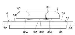
アウタ側の摩擦パッド6とキャリパ3のアウタ脚部3Cとの間に設けられたアウタ側のシム板35は、図11および図12に示すように、取付爪部14と、後述のベース板部36とにより大略構成されている。このベース板部36は、アウタ側の摩擦パッド6(裏板6B)の背面に沿ってディスク周方向と径方向とに延びる略長方形ないし略扇形状の板状部材として形成されている。そして、ベース板部36には、ディスク周方向に延びるように第1の押圧部37と第2の押圧部38が設けられている。   As shown in FIGS. 11 and 12, the outer shim plate 35 provided between the outer friction pad 6 and the outer leg portion 3C of the caliper 3 includes an attachment claw portion 14 and a base plate portion described later. 36. The base plate portion 36 is formed as a substantially rectangular or substantially fan-shaped plate-like member extending in the disk circumferential direction and the radial direction along the back surface of the outer friction pad 6 (back plate 6B). The base plate portion 36 is provided with a first pressing portion 37 and a second pressing portion 38 so as to extend in the disk circumferential direction.

これら第1の押圧部37と第2の押圧部38は、ディスク径方向に離間して互いに平行にシム板35(ベース板部36)と一体に設けられている。これら各押圧部37,38は、摩擦パッド6をシム板35と共に取付部材2に取付けた状態で、キャリパ3のアウタ脚部3Cと摩擦パッド6との間に位置するものである。   The first pressing portion 37 and the second pressing portion 38 are provided integrally with the shim plate 35 (base plate portion 36) so as to be spaced apart from each other in the disk radial direction and parallel to each other. These pressing portions 37 and 38 are positioned between the outer leg 3C of the caliper 3 and the friction pad 6 in a state where the friction pad 6 is attached to the attachment member 2 together with the shim plate 35.

ここで、各押圧部37,38は、シム板35を構成するベース板部36のディスク周方向中央部36Aを残してディスク1の周方向に沿って切起こすことにより形成されている。具体的には、各押圧部37,38は、ディスク周方向に離間して設けられた1対の切起部37A,38Aと、これら各切起部37A,38Aの間にそれぞれ位置してこれら切起部37A,38Aの間を連結する連結部37B,38Bとにより構成されている。   Here, each pressing portion 37, 38 is formed by raising along the circumferential direction of the disc 1 leaving the disc circumferential direction central portion 36 </ b> A of the base plate portion 36 constituting the shim plate 35. Specifically, each of the pressing portions 37 and 38 is positioned between a pair of cut and raised portions 37A and 38A that are provided apart from each other in the circumferential direction of the disk, and these cut and raised portions 37A and 38A, respectively. It is comprised by the connection parts 37B and 38B which connect between the cut-and-raised parts 37A and 38A.

このために、シム板35を構成するベース板部36の上部側には、ディスク周方向中央部36Aを残して該中央部36Aからディスク1の周方向に沿うように略U字状(略コ字状)の切込み37C、37Cが、周方向中央部36Aを挟んで互いに対称に形成されている。そして、各切込み37C、37Cにより挟まれた(囲まれた)部位が、それぞれ第1の押圧部37の切起部37Aとなり、これら各切起部37Aは、図12に示すように、それぞれキャリパ3のアウタ脚部3Cに向けて折曲げられている(起こされている)。これにより、切起部37Aは、シム板35の周方向中央部36Aを残してディスク1の周方向に沿ってピストン4側に切起こすことにより形成されている。   Therefore, on the upper side of the base plate portion 36 constituting the shim plate 35, a substantially U-shaped (substantially rectangular shape) is formed so as to extend from the central portion 36 A along the circumferential direction of the disk 1, leaving the central portion 36 A in the circumferential direction of the disc. (Shaped) 37C and 37C are formed symmetrically with respect to the central portion 36A in the circumferential direction. The portions sandwiched (enclosed) by the respective cuts 37C and 37C become the cut and raised portions 37A of the first pressing portion 37, respectively. As shown in FIG. 12, each of the cut and raised portions 37A is a caliper, respectively. 3 is bent (raised) toward the outer leg 3C. As a result, the cut-and-raised portion 37A is formed by cutting the shim plate 35 toward the piston 4 along the circumferential direction of the disk 1 while leaving the circumferential central portion 36A.

一方、シム板35(ベース板部36)の下部側には、ディスク周方向中央部36Aを残して該中央部36Aからディスク1の周方向に沿うように略U字状(略コ字状)の切込み38C、38Cが、ディスク周方向中央部36Aを挟んで互いに対称に形成されている。そして、各切込み38C、38Cにより挟まれた(囲まれた)部位が、それぞれ第2の押圧部38の切起部38Aとなり、これら各切起部38Aは、図12に示すように、それぞれキャリパ3のアウタ脚部3Cに向けて折曲げられている(起こされている)。これにより、切起部38Aは、シム板35のディスク周方向中央部36Aを残してディスク1の周方向に沿ってピストン4側に切起こすことにより形成されている。   On the other hand, on the lower side of the shim plate 35 (base plate portion 36), the disc circumferential direction center portion 36A is left and the substantially U shape (substantially U shape) extends from the center portion 36A along the circumferential direction of the disc 1. The cuts 38C and 38C are formed symmetrically with respect to the central portion 36A in the disk circumferential direction. The portions sandwiched (enclosed) by the respective cuts 38C and 38C become the cut and raised portions 38A of the second pressing portions 38, respectively. As shown in FIG. 3 is bent (raised) toward the outer leg 3C. As a result, the cut-and-raised part 38A is formed by cutting and raising the shim plate 35 toward the piston 4 along the circumferential direction of the disk 1 while leaving the central part 36A in the circumferential direction of the disk.

なお、アウタ側のシム板35の第1の押圧部37と第2の押圧部38は、ディスク周方向に関する長さ寸法が互いに同じである点で、インナ側のシム板31の第1の押圧部33と第2の押圧部34と相違している。即ち、インナ側のシム板31の第1の押圧部33と第2の押圧部34は、ピストン4の開口端との当接位置に合せて、第1の押圧部33を第2の押圧部34よりも長くしているのに対して、アウタ側のシム板35の第1の押圧部37と第2の押圧部38は、キャリパ3のアウタ脚部3Cとの当接位置に合せて、互いに同じ長さにしている。   The first pressing portion 37 and the second pressing portion 38 of the outer side shim plate 35 have the same length in the circumferential direction of the disk, and therefore the first pressing portion of the inner side shim plate 31 is the same. This is different from the portion 33 and the second pressing portion 34. That is, the first pressing portion 33 and the second pressing portion 34 of the inner shim plate 31 are arranged so that the first pressing portion 33 is in contact with the opening end of the piston 4. 34, while the first pressing portion 37 and the second pressing portion 38 of the outer shim plate 35 are aligned with the contact position of the outer leg portion 3C of the caliper 3, They are the same length.

また、アウタ側のシム板35の第1の押圧部37と第2の押圧部38は、アウタ脚部3Cにより押圧される点で、ピストン4により押圧されるインナ側のシム板31の第1の押圧部33と第2の押圧部34と相違する。   Further, the first pressing portion 37 and the second pressing portion 38 of the outer side shim plate 35 are pressed by the outer leg portion 3 </ b> C, and thus the first of the inner side shim plate 31 pressed by the piston 4. The pressing portion 33 is different from the second pressing portion 34.

ただし、アウタ側のシム板35の第1の押圧部37および第2の押圧部38と、インナ側のシム板31の第1の押圧部33および第2の押圧部34とは、互いの長さ寸法が異なる点と、ピストン4により押圧されるかキャリパ3のアウタ脚部3Cにより押圧されるかで異なる点以外、ほぼ同様の構成および作用効果を有する。このため、アウタ側のシム板35の第1の押圧部37と第2の押圧部38に関するこれ以上の説明は省略する。   However, the 1st press part 37 and the 2nd press part 38 of the outer side shim board 35, and the 1st press part 33 and the 2nd press part 34 of the inner side shim board 31 are mutually long. Except for the difference in length and whether the piston 4 is pressed by the piston 4 or the outer leg 3C of the caliper 3, it has substantially the same configuration and effect. For this reason, the further description regarding the 1st press part 37 of the outer side shim board 35 and the 2nd press part 38 is abbreviate | omitted.

本実施の形態によるディスクブレーキは、上述の如きシム板31,35を用いてブレーキ鳴きを防止するもので、その基本的作用については、上述した第1の実施の形態によるものと格別差異はない。   The disc brake according to the present embodiment uses the shim plates 31 and 35 as described above to prevent brake squeal, and the basic action is not different from that according to the first embodiment described above. .

特に、本実施の形態では、第1の押圧部33,37と第2の押圧部34,38とにより、摩擦パッド5,6のディスク周方向中央でディスク1の径方向に沿った線分X−X上を2箇所位置で押圧する構成としている。このため、本実施の形態の場合も、微圧領域の制動時に、摩擦パッド5,6の振動がピストン4およびアウタ脚部3Cを介してキャリパ3側に伝達されることを低減することができ、微圧鳴きを安定して抑制することができる。   In particular, in the present embodiment, a line segment X along the radial direction of the disk 1 at the center in the disk circumferential direction of the friction pads 5 and 6 by the first pressing parts 33 and 37 and the second pressing parts 34 and 38. -X is configured to be pressed at two positions. For this reason, also in the case of this embodiment, it is possible to reduce the vibration of the friction pads 5 and 6 being transmitted to the caliper 3 side via the piston 4 and the outer leg portion 3C during braking in the low pressure region. In addition, it is possible to stably suppress fine noise.

本実施の形態では、第1の押圧部33,37と第2の押圧部34,38を、ディスク周方向に沿って切起こすことにより形成しているので、各押圧部33,37,34,38をプレス加工等の簡素な加工工程で形成することができ、コストの低減を図ることができる。   In the present embodiment, since the first pressing portions 33 and 37 and the second pressing portions 34 and 38 are formed by cutting up along the circumferential direction of the disk, the pressing portions 33, 37, 34, 38 can be formed by a simple working process such as press working, and the cost can be reduced.

本実施の形態では、インナ側の摩擦パッド5とピストン4との間と、アウタ側の摩擦パッド6とキャリパ3のアウタ脚部3Cとの間の両方に、押圧部33,37,34,38を有するシム板31,35を設ける構成としている。このため、インナ側の摩擦パッド5に起因する微圧鳴きとアウタ側の摩擦パッド6に起因する微圧鳴きとの両方の微圧鳴きを安定して抑制することができる。   In the present embodiment, the pressing portions 33, 37, 34, 38 are provided both between the inner friction pad 5 and the piston 4 and between the outer friction pad 6 and the outer leg 3 C of the caliper 3. It is set as the structure which provides shim board 31 and 35 which has. For this reason, it is possible to stably suppress both the fine pressure squeal caused by the inner friction pad 5 and the fine pressure squeak caused by the outer friction pad 6.

次に、図13および図14は本発明の第4の実施の形態を示している。本実施の形態の特徴は、シム板全体をディスク周方向に沿って波状(凹状)に形成することにより該シム板に押圧部を設ける構成したことにある。なお、本実施の形態では、上述した第1の実施の形態と同一の構成要素に同一の符号を付し、その説明を省略するものとする。   Next, FIG. 13 and FIG. 14 show a fourth embodiment of the present invention. A feature of the present embodiment is that a pressing portion is provided on the shim plate by forming the entire shim plate in a wavy shape (concave shape) along the circumferential direction of the disk. In the present embodiment, the same components as those in the first embodiment described above are denoted by the same reference numerals, and the description thereof is omitted.

インナ側の摩擦パッド5とピストン4との間に設けられたインナ側のシム板41は、取付爪部14と、後述のベース板部42とにより大略構成されている。このベース板部42は、摩擦パッド5(裏板5B)の背面に沿ってディスク周方向と径方向とに延びる略長方形ないし略扇形状の板状部材として形成されたものである。そして、ベース板部42のディスク周方向中央部42Aには、ディスク径方向に延びるように押圧部43がベース板部42と一体に設けられている。   An inner shim plate 41 provided between the inner friction pad 5 and the piston 4 is roughly constituted by a mounting claw portion 14 and a base plate portion 42 described later. The base plate portion 42 is formed as a substantially rectangular or substantially fan-shaped plate-like member extending in the disk circumferential direction and the radial direction along the back surface of the friction pad 5 (back plate 5B). A pressing portion 43 is provided integrally with the base plate portion 42 so as to extend in the disc radial direction at the disc circumferential direction central portion 42A of the base plate portion 42.

即ち、シム板41は、ベース板部42のディスク周方向中央部42Aが摩擦パッド5側に突出するようにディスク1の周方向に沿って波状、より具体的には、凹状に折曲げて形成されている。そして、押圧部43は、シム板41のうち摩擦パッド5側に突出したディスク周方向中央部42Aにより構成されている。   That is, the shim plate 41 is formed by bending the circumferential direction of the disc 1 into a wave shape, more specifically, a concave shape so that the disc circumferential center portion 42A of the base plate portion 42 protrudes toward the friction pad 5 side. Has been. And the press part 43 is comprised by 42 A of disk circumferential direction center parts which protruded in the friction pad 5 side among the shim boards 41. As shown in FIG.

このような押圧部43は、上述した第1の実施の形態の押圧部13と同様に、ピストン4が摩擦パッド5を押圧し始めたとき、即ち、ピストン4の押圧力Fが、微圧領域、例えば液圧0.8MPa以下、より好ましくは、液圧0.5MPa以下となる領域において、摩擦パッド5のディスク周方向中央でディスク径方向に沿った線分X−X上を押圧するものである。   Such a pressing portion 43 is similar to the pressing portion 13 of the first embodiment described above when the piston 4 starts to press the friction pad 5, that is, the pressing force F of the piston 4 is a slight pressure region. For example, in the region where the hydraulic pressure is 0.8 MPa or less, more preferably, the hydraulic pressure is 0.5 MPa or less, the friction pad 5 is pressed on the line segment XX along the disc radial direction at the center in the disc circumferential direction. is there.

本実施の形態によるディスクブレーキは、上述の如きシム板41を用いてブレーキ鳴きを防止するもので、その基本的作用については、上述した第1の実施の形態によるものと格別差異はない。   The disc brake according to the present embodiment uses the shim plate 41 as described above to prevent brake squeal, and the basic action is not particularly different from that according to the first embodiment described above.

特に、本実施の形態では、シム板41(ベース板部42)のうち摩擦パッド5側に突出した周方向中央部42Aを押圧部43として構成しているので、この押圧部43をプレス加工等の簡素な加工工程で形成することができる。しかも、例えばシム板に切起部を形成する構成に比べ、切込み工程、切起こし工程等を省略することもでき、その分、より一層コストの低減を図ることができる。   In particular, in the present embodiment, the circumferential central portion 42A protruding to the friction pad 5 side of the shim plate 41 (base plate portion 42) is configured as the pressing portion 43, so that the pressing portion 43 is pressed or the like. It can be formed by a simple processing step. In addition, for example, the cutting process, the cutting process, and the like can be omitted, and the cost can be further reduced as compared with the configuration in which the cut and raised part is formed on the shim plate.

次に、図15および図16は本発明の第5の実施の形態を示している。本実施の形態の特徴は、シム板全体をディスク周方向に沿って波状(M字状)に形成することにより該シム板に押圧部を設ける構成すると共に、アウタ側の摩擦パッドとキャリパのアウタ脚部との間にも押圧部を有するシム板を設ける構成としたことにある。なお、本実施の形態では、上述した第1の実施の形態と同一の構成要素に同一の符号を付し、その説明を省略するものとする。   Next, FIG. 15 and FIG. 16 show a fifth embodiment of the present invention. A feature of the present embodiment is that the entire shim plate is formed in a wave shape (M-shape) along the circumferential direction of the disk so that a pressing portion is provided on the shim plate, and an outer friction pad and an outer caliper are provided. There is a configuration in which a shim plate having a pressing portion is provided between the leg portions. In the present embodiment, the same components as those in the first embodiment described above are denoted by the same reference numerals, and the description thereof is omitted.

インナ側の摩擦パッド5とピストン4との間に設けられたインナ側のシム板51と、アウタ側の摩擦パッド6とキャリパ3のアウタ脚部3Cとの間に設けたアウタ側のシム板52は、ベース板部53と、取付爪部(図示せず)とにより大略構成されている。このうちのベース板部53は、摩擦パッド5,6(裏板5B,6B)の背面に沿ってディスク周方向と径方向とに延びる略長方形ないし略扇形状の板状部材として形成されたものである。そして、ベース板部53の周方向中央部53Aには、ディスク径方向に延びるように押圧部54がベース板部53と一体に設けられている。   An inner shim plate 51 provided between the inner friction pad 5 and the piston 4, and an outer shim plate 52 provided between the outer friction pad 6 and the outer leg 3 </ b> C of the caliper 3. Is roughly constituted by a base plate portion 53 and an attachment claw portion (not shown). Of these, the base plate portion 53 is formed as a substantially rectangular or substantially fan-shaped plate-like member extending in the disk circumferential direction and the radial direction along the back surface of the friction pads 5 and 6 (back plates 5B and 6B). It is. A pressing portion 54 is provided integrally with the base plate portion 53 so as to extend in the disk radial direction at the circumferential center portion 53A of the base plate portion 53.

即ち、シム板51,52は、ベース板部53の周方向中央部53Aが摩擦パッド5,6側に突出するようにディスク周方向に沿って波状、より具体的には、M字状またはW字状に折曲げて形成されている。そして、押圧部54は、シム板51,52のうち摩擦パッド5,6側に突出したディスク周方向中央部53Aにより構成されている。   That is, the shim plates 51 and 52 are wavy along the circumferential direction of the disk so that the circumferential central portion 53A of the base plate portion 53 protrudes toward the friction pads 5 and 6, more specifically, M-shaped or W-shaped. It is formed by bending it into a letter shape. The pressing portion 54 is constituted by a disc circumferential direction central portion 53A that protrudes toward the friction pads 5 and 6 of the shim plates 51 and 52.

このような押圧部54は、ピストン4が摩擦パッド5を押圧し始めたとき、即ち、ピストン4の押圧力Fが、微圧領域、例えば液圧0.8MPa以下、より好ましくは、液圧0.5MPa以下となる領域において、摩擦パッド5,6のディスク周方向中央でディスク径方向に沿った線分X−X上を押圧するものである。   Such a pressing portion 54 is configured such that when the piston 4 starts to press the friction pad 5, that is, the pressing force F of the piston 4 is a slight pressure region, for example, a hydraulic pressure of 0.8 MPa or less, more preferably a hydraulic pressure of 0. In the region of .5 MPa or less, the friction pads 5 and 6 are pressed on the line segment XX along the disk radial direction at the center in the disk circumferential direction.

本実施の形態によるディスクブレーキは、上述の如きシム板51,52を用いてブレーキ鳴きを防止するもので、その基本的作用については、上述した第1の実施の形態によるものと格別差異はない。   The disc brake according to the present embodiment uses the shim plates 51 and 52 as described above to prevent brake squeal, and the basic action is not different from that according to the first embodiment described above. .

特に、本実施の形態では、シム板51,52(ベース板部53)のうち摩擦パッド5,6側に突出したディスク周方向中央部53Aを押圧部54として構成しているため、この押圧部54をプレス加工等の簡素な加工工程で形成することができる。しかも、例えばシム板に切起部を形成する構成に比べ、切込み工程、切起こし工程等を省略することもでき、その分、より一層コストの低減を図ることができる。   In particular, in the present embodiment, the disk circumferential direction central portion 53A protruding to the friction pads 5 and 6 side of the shim plates 51 and 52 (base plate portion 53) is configured as the pressing portion 54. 54 can be formed by a simple processing step such as pressing. In addition, for example, the cutting process, the cutting process, and the like can be omitted, and the cost can be further reduced as compared with the configuration in which the cut and raised part is formed on the shim plate.

本実施の形態では、インナ側の摩擦パッド5とピストン4との間と、アウタ側の摩擦パッド6とキャリパ3のアウタ脚部3Cとの間の両方に、押圧部54を有するシム板51,52を設ける構成としている。このため、インナ側の摩擦パッド5に起因する微圧鳴きとアウタ側の摩擦パッド6に起因する微圧鳴きとの両方の微圧鳴きを安定して抑制することができる。   In the present embodiment, shim plates 51 each having a pressing portion 54 between the inner friction pad 5 and the piston 4 and between the outer friction pad 6 and the outer leg 3C of the caliper 3. 52 is provided. For this reason, it is possible to stably suppress both the fine pressure squeal caused by the inner friction pad 5 and the fine pressure squeak caused by the outer friction pad 6.

次に、図17ないし図19は本発明の第6の実施の形態を示している。本実施の形態の特徴は、押圧部を有するシム板と別のシム板との2枚のシム板を設ける構成とすると共に、アウタ側の摩擦パッドとキャリパのアウタ脚部との間にも押圧部を有するシム板を設ける構成としたことにある。なお、本実施の形態では、上述した第1の実施の形態と同一の構成要素に同一の符号を付し、その説明を省略するものとする。   Next, FIGS. 17 to 19 show a sixth embodiment of the present invention. A feature of the present embodiment is that two shim plates, ie, a shim plate having a pressing portion and another shim plate, are provided, and the outer side friction pad and the outer leg portion of the caliper are also pressed. In other words, a shim plate having a portion is provided. In the present embodiment, the same components as those in the first embodiment described above are denoted by the same reference numerals, and the description thereof is omitted.

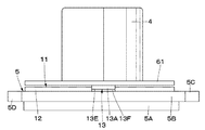
インナ側の摩擦パッド5とピストン4との間には、上述した第1の実施の形態とほぼ同様のシム板11が設けられると共に、該シム板11とピストン4との間には、別のシム板61が設けられている。また、アウタ側の摩擦パッド6とキャリパ3のアウタ脚部3Cとの間には、上述した第1の実施の形態のアウタ側のシム板15に代えてインナ側のシム板11とほぼ同様の構成のシム板11が設けられると共に、該シム板11とアウタ脚部3Cとの間には、別のシム板61が設けられている。   Between the friction pad 5 on the inner side and the piston 4, there is provided a shim plate 11 that is substantially the same as that of the first embodiment described above, and between the shim plate 11 and the piston 4, another shim plate 11 is provided. A shim plate 61 is provided. Further, between the outer friction pad 6 and the outer leg 3C of the caliper 3, it is substantially the same as the inner side shim plate 11 instead of the outer side shim plate 15 of the first embodiment described above. A shim plate 11 having a configuration is provided, and another shim plate 61 is provided between the shim plate 11 and the outer leg 3C.

ここで、シム板11は内側シム板を構成し、別のシム板61は外側シム板を構成している。別のシム板61は、シム板11のベース板部12と同形状の平板として形成されている。また、シム板61には、シム板11のような押圧部13と取付爪部14は設けられていない。なお、必要に応じて、シム板61の周縁に取付爪部を設けてもよい。   Here, the shim plate 11 constitutes an inner shim plate, and the other shim plate 61 constitutes an outer shim plate. Another shim plate 61 is formed as a flat plate having the same shape as the base plate portion 12 of the shim plate 11. Further, the shim plate 61 is not provided with the pressing portion 13 and the mounting claw portion 14 unlike the shim plate 11. In addition, you may provide an attachment nail | claw part in the periphery of the shim board 61 as needed.

本実施の形態によるディスクブレーキは、上述の如きシム板11と別のシム板61とを用いてブレーキ鳴きを防止するもので、その基本的作用については、上述した第1の実施の形態によるものと格別差異はない。   The disc brake according to the present embodiment uses the shim plate 11 as described above and another shim plate 61 to prevent brake noise. The basic operation of the disc brake is according to the first embodiment described above. There is no particular difference.

特に、本実施の形態では、別のシム板61をシム板11の背面側(摩擦パッド5,6と反対側)に設ける構成としているので、先端側が二又状の爪部となったアウタ脚部3Cとアウタ側の摩擦パッド6との間にも、切起部13Aがディスク周方向中央部12Aに設けられたシム板11を設けることができる。このため、アウタ脚部3Cとアウタ側の摩擦パッド6との間に、アウタ脚部3Cの形状に合わせた専用のシム板を、インナ側のシム板11とは別に形成(製造)する必要がなくなり、アウタ側とインナ側とで押圧部13を有するシム板11の共通化を図ることができる。これにより、コストを低減することができる。   In particular, in the present embodiment, since another shim plate 61 is provided on the back side of the shim plate 11 (the side opposite to the friction pads 5 and 6), the outer leg whose tip side is a bifurcated claw portion. A shim plate 11 in which a cut-and-raised portion 13A is provided at the central portion 12A in the disk circumferential direction can also be provided between the portion 3C and the friction pad 6 on the outer side. For this reason, it is necessary to form (manufacture) a dedicated shim plate that matches the shape of the outer leg portion 3C separately from the inner side shim plate 11 between the outer leg portion 3C and the outer friction pad 6. The shim plate 11 having the pressing portion 13 can be shared between the outer side and the inner side. Thereby, cost can be reduced.

しかも、インナ側の摩擦パッド5とピストン4との間と、アウタ側の摩擦パッド6とキャリパ3のアウタ脚部3Cとの間の両方に、押圧部13を有するシム板11を設ける構成としている。このため、インナ側の摩擦パッド5に起因する微圧鳴きとアウタ側の摩擦パッド6に起因する微圧鳴きとの両方の微圧鳴きを安定して抑制することができる。   Moreover, the shim plate 11 having the pressing portion 13 is provided between both the inner friction pad 5 and the piston 4 and between the outer friction pad 6 and the outer leg 3C of the caliper 3. . For this reason, it is possible to stably suppress both the fine pressure squeal caused by the inner friction pad 5 and the fine pressure squeak caused by the outer friction pad 6.

なお、図20に示す変形例のように、上述した第4の実施の形態のシム板41と上述した第6の実施の形態の別のシム板61との2枚のシム板41,61とをインナ側の摩擦パッド5とピストン4との間に設ける構成としてもよい。即ち、別のシム板61は、上述した各実施の形態のシム板11,31,35,41,51,52のうちから適宜選択されるシム板と組合わせて用いることができる。   20, two shim plates 41 and 61, that is, the shim plate 41 of the fourth embodiment described above and another shim plate 61 of the sixth embodiment described above, May be provided between the friction pad 5 on the inner side and the piston 4. That is, the other shim plate 61 can be used in combination with a shim plate appropriately selected from the shim plates 11, 31, 35, 41, 51, and 52 of the above-described embodiments.

次に、図21ないし図23は本発明の第7の実施の形態を示している。本実施の形態の特徴は、ピストンに係止される部材(押圧部材)により押圧部(押圧機構)を構成したことにある。なお、本実施の形態では、上述した第1の実施の形態と同一の構成要素に同一の符号を付し、その説明を省略するものとする。   Next, FIGS. 21 to 23 show a seventh embodiment of the present invention. The feature of this embodiment is that a pressing portion (pressing mechanism) is configured by a member (pressing member) locked to the piston. In the present embodiment, the same components as those in the first embodiment described above are denoted by the same reference numerals, and the description thereof is omitted.

ピストン4の開口端(先端)には、該開口端からディスク軸方向に凹む係止凹部4Aが、径方向に対向する位置(180°離間する位置)に設けられている。そして、これら係止凹部4Aには、押圧部としての押圧部材71が係止されている(取付けられている)。この押圧部材71は、摩擦パッド5とピストン4との間に位置して、該ピストン4が摩擦パッド5を押圧し始めたとき、摩擦パッド5の周方向中央でディスク径方向に沿った線分X−X上を押圧するものである。   At the opening end (tip) of the piston 4, a locking recess 4A that is recessed from the opening end in the disk axial direction is provided at a position facing the radial direction (position spaced 180 °). And the press member 71 as a press part is locked (attached) to 4 A of these latching recessed parts. The pressing member 71 is located between the friction pad 5 and the piston 4, and when the piston 4 starts to press the friction pad 5, a line segment along the disk radial direction at the circumferential center of the friction pad 5. XX is pressed.

押圧部材71は、例えばばね性を有するステンレス鋼板等の矩形状の板材にプレス加工等を施すことにより形成されている。ここで、押圧部材71は、長さ方向両端側に位置してピストン4の各係止凹部4Aに係止される係止部71Aと、該各係止部71Aの間を連結する連結部71Bとにより大略構成されている。そして、連結部71Bの長さ方向中央部には、自由状態(弾性変形していない状態)でピストン4の開口端よりも摩擦パッド5の裏板5B側に突出して当接する当接部72が設けられている。この当接部72は、押圧部材71をピストン4に係止した状態(組付状態)で、摩擦パッド5のディスク周方向中央でディスク径方向に沿った線分X−Xと対向する。   The pressing member 71 is formed by, for example, pressing a rectangular plate material such as a stainless steel plate having spring properties. Here, the pressing member 71 is positioned at both ends in the length direction and is locked to the locking recesses 4A of the piston 4, and a connecting portion 71B that connects the locking portions 71A. And is roughly composed. A contact portion 72 that protrudes and contacts the back plate 5B side of the friction pad 5 from the opening end of the piston 4 in a free state (a state in which the connection portion 71B is not elastically deformed) is provided at the center portion in the length direction of the connection portion 71B. Is provided. The abutting portion 72 faces the line segment XX along the disc radial direction at the center in the disc circumferential direction of the friction pad 5 with the pressing member 71 locked to the piston 4 (assembled state).

図22に示すように、ピストン4の押圧力Fが、微圧領域、例えば液圧0.8MPa以下、より好ましくは、液圧0.5MPa以下となる領域のときは、押圧部材71の当接部72のみが摩擦パッド5の周方向中央でディスク径方向に沿った線分X−X上を一定の長さをもって押圧する。また、ピストン4の押圧力Fが微圧領域のときは、ピストン4の押圧力Fの増大に伴って、当接部72がピストン4の底部側に向けて弾性変形する。   As shown in FIG. 22, when the pressing force F of the piston 4 is in a very low pressure region, for example, a fluid pressure of 0.8 MPa or less, more preferably a fluid pressure of 0.5 MPa or less, the contact of the pressing member 71 Only the portion 72 presses the segment XX along the disk radial direction at the center in the circumferential direction of the friction pad 5 with a certain length. In addition, when the pressing force F of the piston 4 is in the minute pressure region, the contact portion 72 is elastically deformed toward the bottom side of the piston 4 as the pressing force F of the piston 4 increases.

ピストン4の押圧力Fが微圧領域を超えると、図23に示すように、当接部72がピストン4の底部側に最も撓むことにより(最大撓み状態となることにより)、当接部72とピストン4の開口端(先端)とが同一平面となる。このような微圧領域を超えた状態では、ピストン4の開口端全体(係止凹部4Aを除く部位)が摩擦パッド5と当接して該ピストン4全体で摩擦パッド5を押圧する。   When the pressing force F of the piston 4 exceeds the slight pressure region, as shown in FIG. 23, the contact portion 72 is most bent toward the bottom side of the piston 4 (by being in a maximum bending state), thereby causing the contact portion. 72 and the open end (tip) of the piston 4 are flush with each other. In such a state where the fine pressure region is exceeded, the entire open end of the piston 4 (the portion excluding the locking recess 4A) contacts the friction pad 5 and presses the friction pad 5 with the piston 4 as a whole.

これにより、ピストン4の押圧力Fが微圧領域においては、該ピストン4の押圧力Fを、当接部72を介して摩擦パッド5に伝達し、微圧領域を超えてからは、ピストン4の押圧力Fを該ピストン4のディスク周方向全体、詳細には、ピストン4の開口端のうち係止凹部4Aを除く部位で、かつ、摩擦パッド5とディスク1の軸方向に重なる部位の全体で摩擦パッド5に伝達できるように構成している。   As a result, when the pressing force F of the piston 4 is in the low pressure region, the pressing force F of the piston 4 is transmitted to the friction pad 5 via the contact portion 72, and after exceeding the small pressure region, the piston 4 Of the piston 4 in the entire disk circumferential direction, specifically, the entire portion of the opening end of the piston 4 excluding the locking recess 4A and the portion overlapping the friction pad 5 and the disk 1 in the axial direction. It is comprised so that it can transmit to the friction pad 5.

本実施の形態によるディスクブレーキは、上述の如き押圧部材71を用いてブレーキ鳴きを防止するもので、その基本的作用については、摩擦パッド5の線分X−X上をシム板とは別体の押圧部材71により押圧する点で異なる以外、上述した第1の実施の形態によるものと格別差異はない。   The disc brake according to the present embodiment uses the pressing member 71 as described above to prevent brake squealing, and its basic operation is separated from the shim plate on the line XX of the friction pad 5. There is no particular difference from that according to the first embodiment described above except that the pressing member 71 is different from the first embodiment.

特に、本実施の形態では、ピストン4に係止される押圧部材71により押圧部を構成している。換言すれば、シム板とは別の部材である押圧部材71により押圧部(押圧機構)を構成している。このため、摩擦パッド5の背面にシム板を設けない構成でも、微圧領域の制動時に、摩擦パッド5の振動がピストン4を介してキャリパ3側に伝達されることを低減することができ、微圧鳴きを安定して抑制することができる。   In particular, in the present embodiment, the pressing portion is configured by the pressing member 71 that is locked to the piston 4. In other words, the pressing member (pressing mechanism) is configured by the pressing member 71 which is a member different from the shim plate. For this reason, even in a configuration in which no shim plate is provided on the back surface of the friction pad 5, it is possible to reduce the vibration of the friction pad 5 transmitted to the caliper 3 side via the piston 4 during braking in the low pressure region. Slight squealing can be stably suppressed.

なお、上述した第1の実施の形態では、シム板11のディスク周方向中央部12Aの一部(ディスク径方向に関する両端側)をピストン4側に切起こすことにより押圧部13を構成した場合を例に挙げて説明した。しかし、これに限らず、例えば、シム板のディスク周方向中央部の一部(例えば、ディスクの径方向に関する中間部)を摩擦パッド側に切起こすことにより押圧部を構成してもよい。   In the first embodiment described above, a case where the pressing portion 13 is configured by raising part of the central portion 12A in the disk circumferential direction of the shim plate 11 (both ends on the disk radial direction) to the piston 4 side. Explained with an example. However, the present invention is not limited to this, and for example, the pressing portion may be configured by raising a part of the central portion of the shim plate in the circumferential direction of the disc (for example, an intermediate portion in the radial direction of the disc) to the friction pad side.

上述した第3の実施の形態では、押圧部33,34,37,38は、摩擦パッド5,6のディスク周方向中央でディスク径方向に沿った線分X−X上の2箇所位置を押圧する構成とした場合を例に挙げて説明した。しかし、これに限らず、例えば、押圧部を3個以上設けることにより、摩擦パッドの周方向中央でディスク径方向に沿った線分上の3箇所以上の位置を押圧する構成としてもよい。   In the third embodiment described above, the pressing portions 33, 34, 37, 38 press two positions on the line segment XX along the disk radial direction at the center in the disk circumferential direction of the friction pads 5, 6. The case where it was set as the example demonstrated and demonstrated. However, the present invention is not limited to this. For example, by providing three or more pressing portions, it is possible to press three or more positions on a line segment along the disk radial direction at the circumferential center of the friction pad.

上述した実施の形態では、キャリパ3のインナ脚部3Aにシリンダ3Dを介してピストン4を摺動可能に設け、キャリパ3のアウタ脚部3Cをアウタ側の摩擦パッド6に当接させる構成とした所謂フローティングキャリパ型のディスクブレーキを例に挙げて説明した。しかし、これに限らず、例えばキャリパのインナ側とアウタ側とにそれぞれピストンを設ける構成とした所謂対向ピストン型のディスクブレーキに適用してもよい。   In the embodiment described above, the piston 4 is slidably provided on the inner leg portion 3A of the caliper 3 via the cylinder 3D, and the outer leg portion 3C of the caliper 3 is brought into contact with the friction pad 6 on the outer side. A so-called floating caliper type disc brake has been described as an example. However, the present invention is not limited to this. For example, the present invention may be applied to a so-called opposed piston type disc brake in which pistons are provided on the inner side and the outer side of a caliper.

以上の実施の形態によれば、ピストンと摩擦パッドとの間に、該摩擦パッドのディスク周方向中央でディスク径方向に沿った線分上を押圧する押圧部(押圧機構)を設ける構成としている。そして、ピストンが摩擦パッドを押圧し始めたときに、押圧部により、ピストンの押圧力を摩擦パッドに伝達できるように構成している。このため、ピストンの押圧力が微圧領域となる微圧領域の制動時に、摩擦パッドは、微圧鳴き特有の振動モードである摩擦パッドの軸方向の一次曲げモーメントの節に対応する線分上の部位が押圧部により押圧される。これにより、微圧領域の制動時に、摩擦パッドの振動が、ピストンを介してキャリパ側に伝達されることを低減することができ、微圧鳴きを安定して抑制することができる。   According to the above embodiment, the pressing portion (pressing mechanism) is provided between the piston and the friction pad to press the line segment along the disk radial direction at the center in the disk circumferential direction of the friction pad. . And when a piston begins to press a friction pad, it is comprised so that the pressing force of a piston can be transmitted to a friction pad by a press part. For this reason, when braking in the low pressure region where the piston pressing force is in the low pressure region, the friction pad is on the line corresponding to the node of the primary bending moment in the axial direction of the friction pad, which is a vibration mode peculiar to low pressure noise. Is pressed by the pressing portion. Accordingly, it is possible to reduce the vibration of the friction pad transmitted to the caliper side through the piston during braking in the low pressure region, and to suppress the low pressure noise stably.

しかも、押圧部は、グリースやシム板に積層されるゴム等に比べ経時劣化の影響を受けにくくできる、言い換えれば、経時劣化しにくくできるため、長期間の使用に拘わらず微圧鳴きを安定して抑制することができる。さらに、押圧部は、摩擦パッドのディスク周方向中央部を押圧するため、摩擦パッドのライニングの摩耗状態に拘わらず、摩擦パッドが新品のときから交換の時期に至るまで、微圧鳴きを安定して抑制することができる。   In addition, the pressing part can be less susceptible to the effects of deterioration over time compared to grease or rubber laminated on the shim plate, in other words, it can be resistant to deterioration over time. Can be suppressed. Furthermore, since the pressing part presses the center part in the disk circumferential direction of the friction pad, the squeal noise is stabilized from the time when the friction pad is new to the time of replacement, regardless of the wear state of the friction pad lining. Can be suppressed.

実施の形態によれば、摩擦パッドのディスク周方向中央でディスク径方向に沿った線分上を2箇所以上で押圧する構成としているので、微圧領域の制動時に、摩擦パッドの振動がピストンおよびアウタ脚部を介してキャリパ側に伝達されることを低減することができ、微圧鳴きを安定して抑制することができる。   According to the embodiment, since the friction pad is pressed at two or more locations along the disk radial direction at the center of the disk in the circumferential direction of the friction pad, the vibration of the friction pad is caused by the piston and Transmission to the caliper side via the outer leg portion can be reduced, and a slight noise can be stably suppressed.

実施の形態によれば、押圧部(押圧機構)はシム板に一体に設ける構成としているので、例えば押圧部をプレス加工により容易に、しかも、例えばシム板の形成作業と同時に形成することができる。このため、シム板にグリースを塗布する構成や積層シム板を用いる構成に比べ、コストを低減することができる。   According to the embodiment, since the pressing portion (pressing mechanism) is provided integrally with the shim plate, for example, the pressing portion can be easily formed by pressing, for example, simultaneously with the shim plate forming operation. . For this reason, cost can be reduced compared with the structure which apply | coats grease to a shim board, or the structure which uses a lamination shim board.

実施の形態によれば、押圧部は、シム板のディスク周方向中央部をディスク径方向に沿って切起こすことにより形成しているので、押圧部をプレス加工等の簡素な加工工程で形成することができる。このため、この面からも、コストを低減することができる。   According to the embodiment, the pressing part is formed by cutting and raising the central part of the shim plate in the circumferential direction of the disk along the radial direction of the disk. Therefore, the pressing part is formed by a simple processing step such as pressing. be able to. For this reason, cost can be reduced also from this aspect.

実施の形態によれば、押圧部の切起部の幅寸法をディスク周方向に関するシム板の幅寸法の1/2以下に設定しているので、押圧部により摩擦パッドのディスク周方向中央部の線分上を一定の面積をもって押圧することができる。このため、この面からも、微圧鳴きを安定して抑制することができる。   According to the embodiment, since the width dimension of the cut-and-raised part of the pressing part is set to ½ or less of the width dimension of the shim plate with respect to the disk circumferential direction, the pressing part has a central part in the disk circumferential direction of the friction pad. The line segment can be pressed with a certain area. For this reason, it is possible to stably suppress the slight noise from this aspect.

実施の形態によれば、押圧部を、シム板のディスク周方向中央部を残してディスク周方向に沿って切起こすことにより形成しているので、押圧部をプレス加工等の簡素な加工工程で形成することができ、コストの低減を図ることができる。   According to the embodiment, since the pressing portion is formed by raising the shim plate along the circumferential direction of the disk while leaving the central portion in the circumferential direction of the disk, the pressing portion is formed by a simple processing step such as press working. Thus, the cost can be reduced.

実施の形態によれば、シム板のうち摩擦パッド側に突出したディスク周方向中央部を押圧部として構成しているので、この押圧部をプレス加工等の簡素な加工工程で形成することができる。しかも、例えばシム板に切起部を形成する構成に比べ、切込み工程、切起こし工程等を省略することもでき、その分、より一層コストの低減を図ることができる。   According to the embodiment, since the central portion in the circumferential direction of the disk protruding to the friction pad side of the shim plate is configured as the pressing portion, the pressing portion can be formed by a simple processing step such as pressing. . In addition, for example, the cutting process, the cutting process, and the like can be omitted, and the cost can be further reduced as compared with the configuration in which the cut and raised part is formed on the shim plate.

実施の形態によれば、押圧部(押圧機構)をピストンに係止される部材に設ける構成としているので、摩擦パッドの背面にシム板を設けない構成でも、微圧領域の制動時に、摩擦パッドの振動が、ピストンを介してキャリパ側に伝達されることを低減することができ、微圧鳴きを安定して抑制することができる。   According to the embodiment, since the pressing portion (pressing mechanism) is provided on the member that is locked to the piston, the friction pad can be used for braking in the low pressure region even when the shim plate is not provided on the back surface of the friction pad. Can be reduced from being transmitted to the caliper side via the piston, and the slight noise can be stably suppressed.

実施の形態によれば、ピストンの押圧力Fが、微圧領域、例えば、液圧0.8MPa以下、より好ましくは、0.5MPa以下の領域において、該ピストンの押圧力が押圧部を介して摩擦パッドに伝達される構成としているので、ディスクに摩擦パッドが当たり始める程度、即ち、ブレーキペダルに少し足を載せた程度の微圧領域の制動時における微圧鳴きを安定して抑制することができる。   According to the embodiment, in a region where the piston pressing force F is in a slight pressure region, for example, a hydraulic pressure of 0.8 MPa or less, more preferably 0.5 MPa or less, the piston pressing force is applied via the pressing portion. Since it is configured to be transmitted to the friction pad, it is possible to stably suppress a slight squeal when braking in a minute pressure region such that the friction pad starts to hit the disk, that is, a little foot is put on the brake pedal. it can.

1 ディスク
2 取付部材(固定部)
3 キャリパ
4 ピストン
5 インナ側の摩擦パッド
6 アウタ側の摩擦パッド
11,31,41,51 インナ側のシム板
12A,32A,36A,42A,53A 周方向中央部
13,43,54 押圧部
13A 切起部
15,35,52 アウタ側のシム板
33 第1の押圧部(押圧機構)
33A 切起部
34 第2の押圧部(押圧機構)
34A 切起部
71 押圧部材(押圧機構)
1 Disc 2 Mounting member (fixed part)
3 Caliper 4 Piston 5 Inner side friction pad 6 Outer side friction pad 11, 31, 41, 51 Inner side shim plate 12A, 32A, 36A, 42A, 53A Circumferential center portion 13, 43, 54 Pressing portion 13A Cutting Origin 15, 15, 52 Outer side shim plate 33 First pressing portion (pressing mechanism)
33A Cut and raised part 34 Second pressing part (pressing mechanism)
34A Cut and raised part 71 Pressing member (pressing mechanism)

Claims (7)

車両の固定部に対して回転可能なディスクの外周側をディスク軸方向に跨いで配置されるキャリパと、該キャリパのディスク軸方向の少なくとも一側に設けられているピストンと、該ピストンにより前記ディスクの両面に押圧される一対の摩擦パッドとを備えてなるディスクブレーキにおいて、
前記ピストンと前記摩擦パッドとの間には、前記ピストンが前記摩擦パッドを押圧し始めたとき、前記ピストンのディスク周方向中央で該摩擦パッドを押圧する押圧機構を設け、
該押圧機構は、前記摩擦パッドのディスク周方向中央で前記ディスク径方向に延び前記摩擦パッドに当接する当接部と、該当接部の両端にそれぞれ離間して設けられ、ディスク径方向に沿って切起こされると共に弾性力を有する第1および第2の突出部と、を備える、ディスクブレーキ。
A caliper that is disposed across the outer peripheral side of a disc that is rotatable relative to a fixed part of a vehicle in the disc axial direction, a piston that is provided on at least one side of the caliper in the disc axial direction, and the disc by the piston In a disc brake comprising a pair of friction pads pressed on both sides of
Between the piston and the friction pad, when the piston starts to press the friction pad, a pressing mechanism that presses the friction pad at the center in the disk circumferential direction of the piston is provided,
Push pressure mechanism, the abutment portion abutting the disk circumferential direction central portion to the friction pad extending to the disk radial direction of the friction pad, provided apart from each end of the abutting portion, in the disk radial direction A disc brake comprising: first and second protrusions that are cut and raised along with elastic force .
前記摩擦パッドと前記ピストンとの間にはシム板を設け、前記押圧機構は、該シム板に一体に設ける構成としてなる請求項1に記載のディスクブレーキ。 The disc brake according to claim 1, wherein a shim plate is provided between the friction pad and the piston, and the pressing mechanism is provided integrally with the shim plate. 前記ディスクを跨いで前記キャリパの車両側の部位と該車両側とは反対側の部位を連結するブリッジ部を備え、
前記第1の突出部は、ディスク径方向、かつ、前記ブリッジ部に向かう方向に、前記摩擦パッドよりも突出している、請求項1または2に記載のディスクブレーキ。
A bridge portion is provided that connects a portion of the caliper on the vehicle side and a portion on the opposite side of the vehicle across the disk,
3. The disc brake according to claim 1, wherein the first projecting portion projects from the friction pad in a disc radial direction and in a direction toward the bridge portion .
前記第2の突出部は、ディスク径方向、かつ、前記ブリッジ部に向かう方向とは反対の方向に、前記摩擦パッドよりも突出している、請求項3に記載のディスクブレーキ。 The disc brake according to claim 3 , wherein the second projecting portion projects beyond the friction pad in a disc radial direction and in a direction opposite to the direction toward the bridge portion . 前記第1および第2の突出部の幅寸法は、前記シム板のディスク周方向の寸法の1/2以下に設定してなる請求項2ないし4の何れか一に記載のディスクブレーキ。 The disc brake according to any one of claims 2 to 4 , wherein a width dimension of the first and second protrusions is set to ½ or less of a dimension of the shim plate in a circumferential direction of the disc. 前記押圧機構は、前記ピストンに係止される部材により構成してなる請求項1に記載のディスクブレーキ。 The pressing mechanism, disc brake according to claim 1 comprising constituted by members to be locked before the Kipi piston. 前記摩擦パッドは、前記ピストンの押圧力が液圧0.8MPa以下の微圧領域において、該ピストンの押圧力が前記押圧機構を介して伝達される構成としてなる請求項1ないし6の何れか一に記載のディスクブレーキ。 Said friction pads, the low pressure range pressure is below hydraulic 0.8MPa of the piston, any one of claims 1 becomes a structure in which the pressing force of the piston is transmitted through the pressing mechanism 6 Disc brake as described in.
JP2011146793A 2011-06-30 2011-06-30 Disc brake Expired - Fee Related JP5815308B2 (en)

Priority Applications (4)

Application Number Priority Date Filing Date Title
JP2011146793A JP5815308B2 (en) 2011-06-30 2011-06-30 Disc brake
DE201210210985 DE102012210985A1 (en) 2011-06-30 2012-06-27 disc brake
CN201210223571.2A CN102852999B (en) 2011-06-30 2012-06-29 Disk brake
US13/537,620 US9027716B2 (en) 2011-06-30 2012-06-29 Disk brake

Applications Claiming Priority (1)

Application Number Priority Date Filing Date Title
JP2011146793A JP5815308B2 (en) 2011-06-30 2011-06-30 Disc brake

Publications (3)

Publication Number Publication Date
JP2013015164A JP2013015164A (en) 2013-01-24
JP2013015164A5 JP2013015164A5 (en) 2014-07-31
JP5815308B2 true JP5815308B2 (en) 2015-11-17

Family

ID=47355363

Family Applications (1)

Application Number Title Priority Date Filing Date
JP2011146793A Expired - Fee Related JP5815308B2 (en) 2011-06-30 2011-06-30 Disc brake

Country Status (4)

Country Link
US (1) US9027716B2 (en)
JP (1) JP5815308B2 (en)
CN (1) CN102852999B (en)
DE (1) DE102012210985A1 (en)

Families Citing this family (11)

* Cited by examiner, † Cited by third party
Publication number Priority date Publication date Assignee Title
JP5845153B2 (en) * 2012-08-06 2016-01-20 Kyb株式会社 Caliper brake device
DE102012111141A1 (en) * 2012-11-20 2014-05-22 Dr. Ing. H.C. F. Porsche Aktiengesellschaft Spring element for brake of vehicle, has spring tongue which is arranged for allowing resilient loading of spring element by urging element
JP6424782B2 (en) * 2015-09-16 2018-11-21 株式会社アドヴィックス Electric parking brake device
DE102016206027A1 (en) 2016-04-12 2017-10-12 Bayerische Motoren Werke Aktiengesellschaft Brake caliper of a disc brake of a vehicle
KR102582453B1 (en) * 2016-09-05 2023-09-25 에이치엘만도 주식회사 Disc brake
IT201700013292A1 (en) * 2017-02-07 2018-08-07 Campagnolo Srl Pad for bicycle disc brake
KR101908011B1 (en) * 2017-03-23 2018-10-16 주식회사 만도 Disc brake
DE112019007224T5 (en) * 2019-04-17 2021-12-30 Hitachi Astemo, Ltd. Disc brake and laminated spacer
US20230141095A1 (en) * 2019-10-14 2023-05-11 Volvo Truck Corporation Brake disc and a vehicle
US11585397B2 (en) * 2020-11-30 2023-02-21 Honeywell International Inc. Piston cap
CN112594304A (en) * 2020-12-08 2021-04-02 万向钱潮(上海)汽车系统有限公司 Disc brake

Family Cites Families (12)

* Cited by examiner, † Cited by third party
Publication number Priority date Publication date Assignee Title
US3890884A (en) * 1973-11-23 1975-06-24 Borg Warner Hydraulic actuator
JPS5947534A (en) * 1982-09-08 1984-03-17 Nissan Motor Co Ltd Brake pad set spring
DE4140279C1 (en) * 1991-12-06 1993-04-29 Mercedes-Benz Aktiengesellschaft, 7000 Stuttgart, De
FR2697308B1 (en) * 1992-10-26 1995-01-27 Hutchinson Piston for actuation of a disc brake pad.
JP3082567B2 (en) * 1994-04-22 2000-08-28 三菱自動車工業株式会社 Disc brake device
JP3543381B2 (en) * 1994-09-28 2004-07-14 住友電気工業株式会社 Disc brake squeak prevention device
JP3767073B2 (en) * 1997-03-12 2006-04-19 住友電気工業株式会社 Disc brake
CN100359199C (en) * 2003-04-03 2008-01-02 曙制动器工业株式会社 Floating caliper disc brake
FR2870904B1 (en) * 2004-05-27 2006-08-11 Bosch Gmbh Robert NOISE MITIGATION DEVICE IN DISC BRAKE, AND DISC BRAKE PROVIDED WITH SUCH A DEVICE
JP4492437B2 (en) * 2005-05-26 2010-06-30 トヨタ自動車株式会社 Disc brake device for vehicle
JP4650434B2 (en) * 2007-01-26 2011-03-16 トヨタ自動車株式会社 Disc brake device
JP2010175040A (en) 2009-01-30 2010-08-12 Hitachi Automotive Systems Ltd Disc brake

Also Published As

Publication number Publication date
DE102012210985A1 (en) 2013-01-03
US20130001025A1 (en) 2013-01-03
CN102852999A (en) 2013-01-02
JP2013015164A (en) 2013-01-24
CN102852999B (en) 2016-08-24
US9027716B2 (en) 2015-05-12

Similar Documents

Publication Publication Date Title
JP5815308B2 (en) Disc brake
JP5583533B2 (en) Disc brake
JP4803019B2 (en) Disc brake device
JP6818098B2 (en) Disc brake
JP5806872B2 (en) Disc brake
JP6746789B2 (en) Disc brake
CN108626273B (en) Disc brake for vehicle
JP6063299B2 (en) Disc brake
JP6745997B2 (en) Disc brake
JP6099282B2 (en) Disc brakes and friction pads
JP7012161B2 (en) Disc brake
JP6689702B2 (en) Disc brake
WO2018181150A1 (en) Shim for disc brake device
JP7361653B2 (en) disc brake
JP6149273B2 (en) Disc brake
JP2022024201A (en) Disk brake, friction pad, and shim
US20220275842A1 (en) Disc brake
JP2007085439A (en) Disc brake for vehicle
JP3566560B2 (en) Disc brake
JP2008138738A (en) Disc brake
JP2013155797A (en) Disk brake device
JP2013036558A (en) Pad assembly for disk brake
JP6281165B2 (en) Disc brake
JP5790520B2 (en) Disc brake device
JP2014126066A (en) Disk brake for vehicle

Legal Events

Date Code Title Description
A521 Request for written amendment filed

Free format text: JAPANESE INTERMEDIATE CODE: A523

Effective date: 20140617

A621 Written request for application examination

Free format text: JAPANESE INTERMEDIATE CODE: A621

Effective date: 20140617

A977 Report on retrieval

Free format text: JAPANESE INTERMEDIATE CODE: A971007

Effective date: 20150219

A131 Notification of reasons for refusal

Free format text: JAPANESE INTERMEDIATE CODE: A131

Effective date: 20150224

A521 Request for written amendment filed

Free format text: JAPANESE INTERMEDIATE CODE: A523

Effective date: 20150424

TRDD Decision of grant or rejection written
A01 Written decision to grant a patent or to grant a registration (utility model)

Free format text: JAPANESE INTERMEDIATE CODE: A01

Effective date: 20150915

A61 First payment of annual fees (during grant procedure)

Free format text: JAPANESE INTERMEDIATE CODE: A61

Effective date: 20150924

R150 Certificate of patent or registration of utility model

Ref document number: 5815308

Country of ref document: JP

Free format text: JAPANESE INTERMEDIATE CODE: R150

LAPS Cancellation because of no payment of annual fees