JP5814794B2 - Lockable expanding spine retainer - Google Patents
Lockable expanding spine retainer Download PDFInfo
- Publication number
- JP5814794B2 JP5814794B2 JP2011540880A JP2011540880A JP5814794B2 JP 5814794 B2 JP5814794 B2 JP 5814794B2 JP 2011540880 A JP2011540880 A JP 2011540880A JP 2011540880 A JP2011540880 A JP 2011540880A JP 5814794 B2 JP5814794 B2 JP 5814794B2
- Authority
- JP
- Japan
- Prior art keywords
- locking
- support
- spinal implant
- implant
- piston
- Prior art date
- Legal status (The legal status is an assumption and is not a legal conclusion. Google has not performed a legal analysis and makes no representation as to the accuracy of the status listed.)
- Expired - Fee Related
Links
Images


Classifications
-
- A—HUMAN NECESSITIES
- A61—MEDICAL OR VETERINARY SCIENCE; HYGIENE
- A61F—FILTERS IMPLANTABLE INTO BLOOD VESSELS; PROSTHESES; DEVICES PROVIDING PATENCY TO, OR PREVENTING COLLAPSING OF, TUBULAR STRUCTURES OF THE BODY, e.g. STENTS; ORTHOPAEDIC, NURSING OR CONTRACEPTIVE DEVICES; FOMENTATION; TREATMENT OR PROTECTION OF EYES OR EARS; BANDAGES, DRESSINGS OR ABSORBENT PADS; FIRST-AID KITS
- A61F2/00—Filters implantable into blood vessels; Prostheses, i.e. artificial substitutes or replacements for parts of the body; Appliances for connecting them with the body; Devices providing patency to, or preventing collapsing of, tubular structures of the body, e.g. stents
- A61F2/02—Prostheses implantable into the body
- A61F2/30—Joints
- A61F2/44—Joints for the spine, e.g. vertebrae, spinal discs
- A61F2/442—Intervertebral or spinal discs, e.g. resilient
-
- A—HUMAN NECESSITIES
- A61—MEDICAL OR VETERINARY SCIENCE; HYGIENE
- A61F—FILTERS IMPLANTABLE INTO BLOOD VESSELS; PROSTHESES; DEVICES PROVIDING PATENCY TO, OR PREVENTING COLLAPSING OF, TUBULAR STRUCTURES OF THE BODY, e.g. STENTS; ORTHOPAEDIC, NURSING OR CONTRACEPTIVE DEVICES; FOMENTATION; TREATMENT OR PROTECTION OF EYES OR EARS; BANDAGES, DRESSINGS OR ABSORBENT PADS; FIRST-AID KITS
- A61F2/00—Filters implantable into blood vessels; Prostheses, i.e. artificial substitutes or replacements for parts of the body; Appliances for connecting them with the body; Devices providing patency to, or preventing collapsing of, tubular structures of the body, e.g. stents
- A61F2/02—Prostheses implantable into the body
- A61F2/30—Joints
- A61F2/44—Joints for the spine, e.g. vertebrae, spinal discs
- A61F2/4455—Joints for the spine, e.g. vertebrae, spinal discs for the fusion of spinal bodies, e.g. intervertebral fusion of adjacent spinal bodies, e.g. fusion cages
-
- A—HUMAN NECESSITIES
- A61—MEDICAL OR VETERINARY SCIENCE; HYGIENE
- A61F—FILTERS IMPLANTABLE INTO BLOOD VESSELS; PROSTHESES; DEVICES PROVIDING PATENCY TO, OR PREVENTING COLLAPSING OF, TUBULAR STRUCTURES OF THE BODY, e.g. STENTS; ORTHOPAEDIC, NURSING OR CONTRACEPTIVE DEVICES; FOMENTATION; TREATMENT OR PROTECTION OF EYES OR EARS; BANDAGES, DRESSINGS OR ABSORBENT PADS; FIRST-AID KITS
- A61F2/00—Filters implantable into blood vessels; Prostheses, i.e. artificial substitutes or replacements for parts of the body; Appliances for connecting them with the body; Devices providing patency to, or preventing collapsing of, tubular structures of the body, e.g. stents
- A61F2/02—Prostheses implantable into the body
- A61F2/48—Operating or control means, e.g. from outside the body, control of sphincters
- A61F2/482—Electrical means
-
- A—HUMAN NECESSITIES
- A61—MEDICAL OR VETERINARY SCIENCE; HYGIENE
- A61F—FILTERS IMPLANTABLE INTO BLOOD VESSELS; PROSTHESES; DEVICES PROVIDING PATENCY TO, OR PREVENTING COLLAPSING OF, TUBULAR STRUCTURES OF THE BODY, e.g. STENTS; ORTHOPAEDIC, NURSING OR CONTRACEPTIVE DEVICES; FOMENTATION; TREATMENT OR PROTECTION OF EYES OR EARS; BANDAGES, DRESSINGS OR ABSORBENT PADS; FIRST-AID KITS
- A61F2/00—Filters implantable into blood vessels; Prostheses, i.e. artificial substitutes or replacements for parts of the body; Appliances for connecting them with the body; Devices providing patency to, or preventing collapsing of, tubular structures of the body, e.g. stents
- A61F2/02—Prostheses implantable into the body
- A61F2/48—Operating or control means, e.g. from outside the body, control of sphincters
- A61F2/484—Fluid means, i.e. hydraulic or pneumatic
-
- A—HUMAN NECESSITIES
- A61—MEDICAL OR VETERINARY SCIENCE; HYGIENE
- A61F—FILTERS IMPLANTABLE INTO BLOOD VESSELS; PROSTHESES; DEVICES PROVIDING PATENCY TO, OR PREVENTING COLLAPSING OF, TUBULAR STRUCTURES OF THE BODY, e.g. STENTS; ORTHOPAEDIC, NURSING OR CONTRACEPTIVE DEVICES; FOMENTATION; TREATMENT OR PROTECTION OF EYES OR EARS; BANDAGES, DRESSINGS OR ABSORBENT PADS; FIRST-AID KITS
- A61F2/00—Filters implantable into blood vessels; Prostheses, i.e. artificial substitutes or replacements for parts of the body; Appliances for connecting them with the body; Devices providing patency to, or preventing collapsing of, tubular structures of the body, e.g. stents
- A61F2/02—Prostheses implantable into the body
- A61F2/30—Joints
- A61F2/30721—Accessories
- A61F2/30742—Bellows or hose-like seals; Sealing membranes
-
- A—HUMAN NECESSITIES
- A61—MEDICAL OR VETERINARY SCIENCE; HYGIENE
- A61F—FILTERS IMPLANTABLE INTO BLOOD VESSELS; PROSTHESES; DEVICES PROVIDING PATENCY TO, OR PREVENTING COLLAPSING OF, TUBULAR STRUCTURES OF THE BODY, e.g. STENTS; ORTHOPAEDIC, NURSING OR CONTRACEPTIVE DEVICES; FOMENTATION; TREATMENT OR PROTECTION OF EYES OR EARS; BANDAGES, DRESSINGS OR ABSORBENT PADS; FIRST-AID KITS
- A61F2/00—Filters implantable into blood vessels; Prostheses, i.e. artificial substitutes or replacements for parts of the body; Appliances for connecting them with the body; Devices providing patency to, or preventing collapsing of, tubular structures of the body, e.g. stents
- A61F2/02—Prostheses implantable into the body
- A61F2/30—Joints
- A61F2002/30001—Additional features of subject-matter classified in A61F2/28, A61F2/30 and subgroups thereof
- A61F2002/30003—Material related properties of the prosthesis or of a coating on the prosthesis
- A61F2002/3006—Properties of materials and coating materials
- A61F2002/30079—Properties of materials and coating materials magnetic
-
- A—HUMAN NECESSITIES
- A61—MEDICAL OR VETERINARY SCIENCE; HYGIENE
- A61F—FILTERS IMPLANTABLE INTO BLOOD VESSELS; PROSTHESES; DEVICES PROVIDING PATENCY TO, OR PREVENTING COLLAPSING OF, TUBULAR STRUCTURES OF THE BODY, e.g. STENTS; ORTHOPAEDIC, NURSING OR CONTRACEPTIVE DEVICES; FOMENTATION; TREATMENT OR PROTECTION OF EYES OR EARS; BANDAGES, DRESSINGS OR ABSORBENT PADS; FIRST-AID KITS
- A61F2/00—Filters implantable into blood vessels; Prostheses, i.e. artificial substitutes or replacements for parts of the body; Appliances for connecting them with the body; Devices providing patency to, or preventing collapsing of, tubular structures of the body, e.g. stents
- A61F2/02—Prostheses implantable into the body
- A61F2/30—Joints
- A61F2002/30001—Additional features of subject-matter classified in A61F2/28, A61F2/30 and subgroups thereof
- A61F2002/30003—Material related properties of the prosthesis or of a coating on the prosthesis
- A61F2002/3006—Properties of materials and coating materials
- A61F2002/3008—Properties of materials and coating materials radio-opaque, e.g. radio-opaque markers
-
- A—HUMAN NECESSITIES
- A61—MEDICAL OR VETERINARY SCIENCE; HYGIENE
- A61F—FILTERS IMPLANTABLE INTO BLOOD VESSELS; PROSTHESES; DEVICES PROVIDING PATENCY TO, OR PREVENTING COLLAPSING OF, TUBULAR STRUCTURES OF THE BODY, e.g. STENTS; ORTHOPAEDIC, NURSING OR CONTRACEPTIVE DEVICES; FOMENTATION; TREATMENT OR PROTECTION OF EYES OR EARS; BANDAGES, DRESSINGS OR ABSORBENT PADS; FIRST-AID KITS
- A61F2/00—Filters implantable into blood vessels; Prostheses, i.e. artificial substitutes or replacements for parts of the body; Appliances for connecting them with the body; Devices providing patency to, or preventing collapsing of, tubular structures of the body, e.g. stents
- A61F2/02—Prostheses implantable into the body
- A61F2/30—Joints
- A61F2002/30001—Additional features of subject-matter classified in A61F2/28, A61F2/30 and subgroups thereof
- A61F2002/30108—Shapes
- A61F2002/3011—Cross-sections or two-dimensional shapes
- A61F2002/30112—Rounded shapes, e.g. with rounded corners
- A61F2002/30133—Rounded shapes, e.g. with rounded corners kidney-shaped or bean-shaped
-
- A—HUMAN NECESSITIES
- A61—MEDICAL OR VETERINARY SCIENCE; HYGIENE
- A61F—FILTERS IMPLANTABLE INTO BLOOD VESSELS; PROSTHESES; DEVICES PROVIDING PATENCY TO, OR PREVENTING COLLAPSING OF, TUBULAR STRUCTURES OF THE BODY, e.g. STENTS; ORTHOPAEDIC, NURSING OR CONTRACEPTIVE DEVICES; FOMENTATION; TREATMENT OR PROTECTION OF EYES OR EARS; BANDAGES, DRESSINGS OR ABSORBENT PADS; FIRST-AID KITS
- A61F2/00—Filters implantable into blood vessels; Prostheses, i.e. artificial substitutes or replacements for parts of the body; Appliances for connecting them with the body; Devices providing patency to, or preventing collapsing of, tubular structures of the body, e.g. stents
- A61F2/02—Prostheses implantable into the body
- A61F2/30—Joints
- A61F2002/30001—Additional features of subject-matter classified in A61F2/28, A61F2/30 and subgroups thereof
- A61F2002/30316—The prosthesis having different structural features at different locations within the same prosthesis; Connections between prosthetic parts; Special structural features of bone or joint prostheses not otherwise provided for
- A61F2002/30329—Connections or couplings between prosthetic parts, e.g. between modular parts; Connecting elements
- A61F2002/30331—Connections or couplings between prosthetic parts, e.g. between modular parts; Connecting elements made by longitudinally pushing a protrusion into a complementarily-shaped recess, e.g. held by friction fit
- A61F2002/30362—Connections or couplings between prosthetic parts, e.g. between modular parts; Connecting elements made by longitudinally pushing a protrusion into a complementarily-shaped recess, e.g. held by friction fit with possibility of relative movement between the protrusion and the recess
- A61F2002/30364—Rotation about the common longitudinal axis
- A61F2002/30365—Rotation about the common longitudinal axis with additional means for limiting said rotation
-
- A—HUMAN NECESSITIES
- A61—MEDICAL OR VETERINARY SCIENCE; HYGIENE
- A61F—FILTERS IMPLANTABLE INTO BLOOD VESSELS; PROSTHESES; DEVICES PROVIDING PATENCY TO, OR PREVENTING COLLAPSING OF, TUBULAR STRUCTURES OF THE BODY, e.g. STENTS; ORTHOPAEDIC, NURSING OR CONTRACEPTIVE DEVICES; FOMENTATION; TREATMENT OR PROTECTION OF EYES OR EARS; BANDAGES, DRESSINGS OR ABSORBENT PADS; FIRST-AID KITS
- A61F2/00—Filters implantable into blood vessels; Prostheses, i.e. artificial substitutes or replacements for parts of the body; Appliances for connecting them with the body; Devices providing patency to, or preventing collapsing of, tubular structures of the body, e.g. stents
- A61F2/02—Prostheses implantable into the body
- A61F2/30—Joints
- A61F2002/30001—Additional features of subject-matter classified in A61F2/28, A61F2/30 and subgroups thereof
- A61F2002/30316—The prosthesis having different structural features at different locations within the same prosthesis; Connections between prosthetic parts; Special structural features of bone or joint prostheses not otherwise provided for
- A61F2002/30329—Connections or couplings between prosthetic parts, e.g. between modular parts; Connecting elements
- A61F2002/30405—Connections or couplings between prosthetic parts, e.g. between modular parts; Connecting elements made by screwing complementary threads machined on the parts themselves
-
- A—HUMAN NECESSITIES
- A61—MEDICAL OR VETERINARY SCIENCE; HYGIENE
- A61F—FILTERS IMPLANTABLE INTO BLOOD VESSELS; PROSTHESES; DEVICES PROVIDING PATENCY TO, OR PREVENTING COLLAPSING OF, TUBULAR STRUCTURES OF THE BODY, e.g. STENTS; ORTHOPAEDIC, NURSING OR CONTRACEPTIVE DEVICES; FOMENTATION; TREATMENT OR PROTECTION OF EYES OR EARS; BANDAGES, DRESSINGS OR ABSORBENT PADS; FIRST-AID KITS
- A61F2/00—Filters implantable into blood vessels; Prostheses, i.e. artificial substitutes or replacements for parts of the body; Appliances for connecting them with the body; Devices providing patency to, or preventing collapsing of, tubular structures of the body, e.g. stents
- A61F2/02—Prostheses implantable into the body
- A61F2/30—Joints
- A61F2002/30001—Additional features of subject-matter classified in A61F2/28, A61F2/30 and subgroups thereof
- A61F2002/30316—The prosthesis having different structural features at different locations within the same prosthesis; Connections between prosthetic parts; Special structural features of bone or joint prostheses not otherwise provided for
- A61F2002/30329—Connections or couplings between prosthetic parts, e.g. between modular parts; Connecting elements
- A61F2002/30476—Connections or couplings between prosthetic parts, e.g. between modular parts; Connecting elements locked by an additional locking mechanism
- A61F2002/30484—Mechanically expandable devices located on the first prosthetic part for locking into or onto the second prosthetic part
-
- A—HUMAN NECESSITIES
- A61—MEDICAL OR VETERINARY SCIENCE; HYGIENE
- A61F—FILTERS IMPLANTABLE INTO BLOOD VESSELS; PROSTHESES; DEVICES PROVIDING PATENCY TO, OR PREVENTING COLLAPSING OF, TUBULAR STRUCTURES OF THE BODY, e.g. STENTS; ORTHOPAEDIC, NURSING OR CONTRACEPTIVE DEVICES; FOMENTATION; TREATMENT OR PROTECTION OF EYES OR EARS; BANDAGES, DRESSINGS OR ABSORBENT PADS; FIRST-AID KITS
- A61F2/00—Filters implantable into blood vessels; Prostheses, i.e. artificial substitutes or replacements for parts of the body; Appliances for connecting them with the body; Devices providing patency to, or preventing collapsing of, tubular structures of the body, e.g. stents
- A61F2/02—Prostheses implantable into the body
- A61F2/30—Joints
- A61F2002/30001—Additional features of subject-matter classified in A61F2/28, A61F2/30 and subgroups thereof
- A61F2002/30316—The prosthesis having different structural features at different locations within the same prosthesis; Connections between prosthetic parts; Special structural features of bone or joint prostheses not otherwise provided for
- A61F2002/30329—Connections or couplings between prosthetic parts, e.g. between modular parts; Connecting elements
- A61F2002/30476—Connections or couplings between prosthetic parts, e.g. between modular parts; Connecting elements locked by an additional locking mechanism
- A61F2002/30495—Connections or couplings between prosthetic parts, e.g. between modular parts; Connecting elements locked by an additional locking mechanism using a locking ring
-
- A—HUMAN NECESSITIES
- A61—MEDICAL OR VETERINARY SCIENCE; HYGIENE
- A61F—FILTERS IMPLANTABLE INTO BLOOD VESSELS; PROSTHESES; DEVICES PROVIDING PATENCY TO, OR PREVENTING COLLAPSING OF, TUBULAR STRUCTURES OF THE BODY, e.g. STENTS; ORTHOPAEDIC, NURSING OR CONTRACEPTIVE DEVICES; FOMENTATION; TREATMENT OR PROTECTION OF EYES OR EARS; BANDAGES, DRESSINGS OR ABSORBENT PADS; FIRST-AID KITS
- A61F2/00—Filters implantable into blood vessels; Prostheses, i.e. artificial substitutes or replacements for parts of the body; Appliances for connecting them with the body; Devices providing patency to, or preventing collapsing of, tubular structures of the body, e.g. stents
- A61F2/02—Prostheses implantable into the body
- A61F2/30—Joints
- A61F2002/30001—Additional features of subject-matter classified in A61F2/28, A61F2/30 and subgroups thereof
- A61F2002/30316—The prosthesis having different structural features at different locations within the same prosthesis; Connections between prosthetic parts; Special structural features of bone or joint prostheses not otherwise provided for
- A61F2002/30329—Connections or couplings between prosthetic parts, e.g. between modular parts; Connecting elements
- A61F2002/30476—Connections or couplings between prosthetic parts, e.g. between modular parts; Connecting elements locked by an additional locking mechanism
- A61F2002/30505—Connections or couplings between prosthetic parts, e.g. between modular parts; Connecting elements locked by an additional locking mechanism spring biased
-
- A—HUMAN NECESSITIES
- A61—MEDICAL OR VETERINARY SCIENCE; HYGIENE
- A61F—FILTERS IMPLANTABLE INTO BLOOD VESSELS; PROSTHESES; DEVICES PROVIDING PATENCY TO, OR PREVENTING COLLAPSING OF, TUBULAR STRUCTURES OF THE BODY, e.g. STENTS; ORTHOPAEDIC, NURSING OR CONTRACEPTIVE DEVICES; FOMENTATION; TREATMENT OR PROTECTION OF EYES OR EARS; BANDAGES, DRESSINGS OR ABSORBENT PADS; FIRST-AID KITS
- A61F2/00—Filters implantable into blood vessels; Prostheses, i.e. artificial substitutes or replacements for parts of the body; Appliances for connecting them with the body; Devices providing patency to, or preventing collapsing of, tubular structures of the body, e.g. stents
- A61F2/02—Prostheses implantable into the body
- A61F2/30—Joints
- A61F2002/30001—Additional features of subject-matter classified in A61F2/28, A61F2/30 and subgroups thereof
- A61F2002/30316—The prosthesis having different structural features at different locations within the same prosthesis; Connections between prosthetic parts; Special structural features of bone or joint prostheses not otherwise provided for
- A61F2002/30329—Connections or couplings between prosthetic parts, e.g. between modular parts; Connecting elements
- A61F2002/30476—Connections or couplings between prosthetic parts, e.g. between modular parts; Connecting elements locked by an additional locking mechanism
- A61F2002/30514—Connections or couplings between prosthetic parts, e.g. between modular parts; Connecting elements locked by an additional locking mechanism using a locking washer
-
- A—HUMAN NECESSITIES
- A61—MEDICAL OR VETERINARY SCIENCE; HYGIENE
- A61F—FILTERS IMPLANTABLE INTO BLOOD VESSELS; PROSTHESES; DEVICES PROVIDING PATENCY TO, OR PREVENTING COLLAPSING OF, TUBULAR STRUCTURES OF THE BODY, e.g. STENTS; ORTHOPAEDIC, NURSING OR CONTRACEPTIVE DEVICES; FOMENTATION; TREATMENT OR PROTECTION OF EYES OR EARS; BANDAGES, DRESSINGS OR ABSORBENT PADS; FIRST-AID KITS
- A61F2/00—Filters implantable into blood vessels; Prostheses, i.e. artificial substitutes or replacements for parts of the body; Appliances for connecting them with the body; Devices providing patency to, or preventing collapsing of, tubular structures of the body, e.g. stents
- A61F2/02—Prostheses implantable into the body
- A61F2/30—Joints
- A61F2002/30001—Additional features of subject-matter classified in A61F2/28, A61F2/30 and subgroups thereof
- A61F2002/30316—The prosthesis having different structural features at different locations within the same prosthesis; Connections between prosthetic parts; Special structural features of bone or joint prostheses not otherwise provided for
- A61F2002/30329—Connections or couplings between prosthetic parts, e.g. between modular parts; Connecting elements
- A61F2002/30518—Connections or couplings between prosthetic parts, e.g. between modular parts; Connecting elements with possibility of relative movement between the prosthetic parts
- A61F2002/3052—Connections or couplings between prosthetic parts, e.g. between modular parts; Connecting elements with possibility of relative movement between the prosthetic parts unrestrained in only one direction, e.g. moving unidirectionally
- A61F2002/30522—Connections or couplings between prosthetic parts, e.g. between modular parts; Connecting elements with possibility of relative movement between the prosthetic parts unrestrained in only one direction, e.g. moving unidirectionally releasable, e.g. using a releasable ratchet
-
- A—HUMAN NECESSITIES
- A61—MEDICAL OR VETERINARY SCIENCE; HYGIENE
- A61F—FILTERS IMPLANTABLE INTO BLOOD VESSELS; PROSTHESES; DEVICES PROVIDING PATENCY TO, OR PREVENTING COLLAPSING OF, TUBULAR STRUCTURES OF THE BODY, e.g. STENTS; ORTHOPAEDIC, NURSING OR CONTRACEPTIVE DEVICES; FOMENTATION; TREATMENT OR PROTECTION OF EYES OR EARS; BANDAGES, DRESSINGS OR ABSORBENT PADS; FIRST-AID KITS
- A61F2/00—Filters implantable into blood vessels; Prostheses, i.e. artificial substitutes or replacements for parts of the body; Appliances for connecting them with the body; Devices providing patency to, or preventing collapsing of, tubular structures of the body, e.g. stents
- A61F2/02—Prostheses implantable into the body
- A61F2/30—Joints
- A61F2002/30001—Additional features of subject-matter classified in A61F2/28, A61F2/30 and subgroups thereof
- A61F2002/30316—The prosthesis having different structural features at different locations within the same prosthesis; Connections between prosthetic parts; Special structural features of bone or joint prostheses not otherwise provided for
- A61F2002/30329—Connections or couplings between prosthetic parts, e.g. between modular parts; Connecting elements
- A61F2002/30518—Connections or couplings between prosthetic parts, e.g. between modular parts; Connecting elements with possibility of relative movement between the prosthetic parts
- A61F2002/30523—Connections or couplings between prosthetic parts, e.g. between modular parts; Connecting elements with possibility of relative movement between the prosthetic parts by means of meshing gear teeth
- A61F2002/30525—Worm gears
-
- A—HUMAN NECESSITIES
- A61—MEDICAL OR VETERINARY SCIENCE; HYGIENE
- A61F—FILTERS IMPLANTABLE INTO BLOOD VESSELS; PROSTHESES; DEVICES PROVIDING PATENCY TO, OR PREVENTING COLLAPSING OF, TUBULAR STRUCTURES OF THE BODY, e.g. STENTS; ORTHOPAEDIC, NURSING OR CONTRACEPTIVE DEVICES; FOMENTATION; TREATMENT OR PROTECTION OF EYES OR EARS; BANDAGES, DRESSINGS OR ABSORBENT PADS; FIRST-AID KITS
- A61F2/00—Filters implantable into blood vessels; Prostheses, i.e. artificial substitutes or replacements for parts of the body; Appliances for connecting them with the body; Devices providing patency to, or preventing collapsing of, tubular structures of the body, e.g. stents
- A61F2/02—Prostheses implantable into the body
- A61F2/30—Joints
- A61F2002/30001—Additional features of subject-matter classified in A61F2/28, A61F2/30 and subgroups thereof
- A61F2002/30316—The prosthesis having different structural features at different locations within the same prosthesis; Connections between prosthetic parts; Special structural features of bone or joint prostheses not otherwise provided for
- A61F2002/30535—Special structural features of bone or joint prostheses not otherwise provided for
- A61F2002/30537—Special structural features of bone or joint prostheses not otherwise provided for adjustable
- A61F2002/3055—Special structural features of bone or joint prostheses not otherwise provided for adjustable for adjusting length
-
- A—HUMAN NECESSITIES
- A61—MEDICAL OR VETERINARY SCIENCE; HYGIENE
- A61F—FILTERS IMPLANTABLE INTO BLOOD VESSELS; PROSTHESES; DEVICES PROVIDING PATENCY TO, OR PREVENTING COLLAPSING OF, TUBULAR STRUCTURES OF THE BODY, e.g. STENTS; ORTHOPAEDIC, NURSING OR CONTRACEPTIVE DEVICES; FOMENTATION; TREATMENT OR PROTECTION OF EYES OR EARS; BANDAGES, DRESSINGS OR ABSORBENT PADS; FIRST-AID KITS
- A61F2/00—Filters implantable into blood vessels; Prostheses, i.e. artificial substitutes or replacements for parts of the body; Appliances for connecting them with the body; Devices providing patency to, or preventing collapsing of, tubular structures of the body, e.g. stents
- A61F2/02—Prostheses implantable into the body
- A61F2/30—Joints
- A61F2002/30001—Additional features of subject-matter classified in A61F2/28, A61F2/30 and subgroups thereof
- A61F2002/30316—The prosthesis having different structural features at different locations within the same prosthesis; Connections between prosthetic parts; Special structural features of bone or joint prostheses not otherwise provided for
- A61F2002/30535—Special structural features of bone or joint prostheses not otherwise provided for
- A61F2002/30579—Special structural features of bone or joint prostheses not otherwise provided for with mechanically expandable devices, e.g. fixation devices
-
- A—HUMAN NECESSITIES
- A61—MEDICAL OR VETERINARY SCIENCE; HYGIENE
- A61F—FILTERS IMPLANTABLE INTO BLOOD VESSELS; PROSTHESES; DEVICES PROVIDING PATENCY TO, OR PREVENTING COLLAPSING OF, TUBULAR STRUCTURES OF THE BODY, e.g. STENTS; ORTHOPAEDIC, NURSING OR CONTRACEPTIVE DEVICES; FOMENTATION; TREATMENT OR PROTECTION OF EYES OR EARS; BANDAGES, DRESSINGS OR ABSORBENT PADS; FIRST-AID KITS
- A61F2/00—Filters implantable into blood vessels; Prostheses, i.e. artificial substitutes or replacements for parts of the body; Appliances for connecting them with the body; Devices providing patency to, or preventing collapsing of, tubular structures of the body, e.g. stents
- A61F2/02—Prostheses implantable into the body
- A61F2/30—Joints
- A61F2002/30001—Additional features of subject-matter classified in A61F2/28, A61F2/30 and subgroups thereof
- A61F2002/30316—The prosthesis having different structural features at different locations within the same prosthesis; Connections between prosthetic parts; Special structural features of bone or joint prostheses not otherwise provided for
- A61F2002/30535—Special structural features of bone or joint prostheses not otherwise provided for
- A61F2002/30581—Special structural features of bone or joint prostheses not otherwise provided for having a pocket filled with fluid, e.g. liquid
-
- A—HUMAN NECESSITIES
- A61—MEDICAL OR VETERINARY SCIENCE; HYGIENE
- A61F—FILTERS IMPLANTABLE INTO BLOOD VESSELS; PROSTHESES; DEVICES PROVIDING PATENCY TO, OR PREVENTING COLLAPSING OF, TUBULAR STRUCTURES OF THE BODY, e.g. STENTS; ORTHOPAEDIC, NURSING OR CONTRACEPTIVE DEVICES; FOMENTATION; TREATMENT OR PROTECTION OF EYES OR EARS; BANDAGES, DRESSINGS OR ABSORBENT PADS; FIRST-AID KITS
- A61F2/00—Filters implantable into blood vessels; Prostheses, i.e. artificial substitutes or replacements for parts of the body; Appliances for connecting them with the body; Devices providing patency to, or preventing collapsing of, tubular structures of the body, e.g. stents
- A61F2/02—Prostheses implantable into the body
- A61F2/30—Joints
- A61F2002/30001—Additional features of subject-matter classified in A61F2/28, A61F2/30 and subgroups thereof
- A61F2002/30316—The prosthesis having different structural features at different locations within the same prosthesis; Connections between prosthetic parts; Special structural features of bone or joint prostheses not otherwise provided for
- A61F2002/30535—Special structural features of bone or joint prostheses not otherwise provided for
- A61F2002/30589—Sealing means
-
- A—HUMAN NECESSITIES
- A61—MEDICAL OR VETERINARY SCIENCE; HYGIENE
- A61F—FILTERS IMPLANTABLE INTO BLOOD VESSELS; PROSTHESES; DEVICES PROVIDING PATENCY TO, OR PREVENTING COLLAPSING OF, TUBULAR STRUCTURES OF THE BODY, e.g. STENTS; ORTHOPAEDIC, NURSING OR CONTRACEPTIVE DEVICES; FOMENTATION; TREATMENT OR PROTECTION OF EYES OR EARS; BANDAGES, DRESSINGS OR ABSORBENT PADS; FIRST-AID KITS
- A61F2/00—Filters implantable into blood vessels; Prostheses, i.e. artificial substitutes or replacements for parts of the body; Appliances for connecting them with the body; Devices providing patency to, or preventing collapsing of, tubular structures of the body, e.g. stents
- A61F2/02—Prostheses implantable into the body
- A61F2/30—Joints
- A61F2002/30001—Additional features of subject-matter classified in A61F2/28, A61F2/30 and subgroups thereof
- A61F2002/30316—The prosthesis having different structural features at different locations within the same prosthesis; Connections between prosthetic parts; Special structural features of bone or joint prostheses not otherwise provided for
- A61F2002/30535—Special structural features of bone or joint prostheses not otherwise provided for
- A61F2002/30601—Special structural features of bone or joint prostheses not otherwise provided for telescopic
-
- A—HUMAN NECESSITIES
- A61—MEDICAL OR VETERINARY SCIENCE; HYGIENE
- A61F—FILTERS IMPLANTABLE INTO BLOOD VESSELS; PROSTHESES; DEVICES PROVIDING PATENCY TO, OR PREVENTING COLLAPSING OF, TUBULAR STRUCTURES OF THE BODY, e.g. STENTS; ORTHOPAEDIC, NURSING OR CONTRACEPTIVE DEVICES; FOMENTATION; TREATMENT OR PROTECTION OF EYES OR EARS; BANDAGES, DRESSINGS OR ABSORBENT PADS; FIRST-AID KITS
- A61F2/00—Filters implantable into blood vessels; Prostheses, i.e. artificial substitutes or replacements for parts of the body; Appliances for connecting them with the body; Devices providing patency to, or preventing collapsing of, tubular structures of the body, e.g. stents
- A61F2/02—Prostheses implantable into the body
- A61F2/30—Joints
- A61F2/30767—Special external or bone-contacting surface, e.g. coating for improving bone ingrowth
- A61F2/30771—Special external or bone-contacting surface, e.g. coating for improving bone ingrowth applied in original prostheses, e.g. holes or grooves
- A61F2002/30841—Sharp anchoring protrusions for impaction into the bone, e.g. sharp pins, spikes
-
- A—HUMAN NECESSITIES
- A61—MEDICAL OR VETERINARY SCIENCE; HYGIENE
- A61F—FILTERS IMPLANTABLE INTO BLOOD VESSELS; PROSTHESES; DEVICES PROVIDING PATENCY TO, OR PREVENTING COLLAPSING OF, TUBULAR STRUCTURES OF THE BODY, e.g. STENTS; ORTHOPAEDIC, NURSING OR CONTRACEPTIVE DEVICES; FOMENTATION; TREATMENT OR PROTECTION OF EYES OR EARS; BANDAGES, DRESSINGS OR ABSORBENT PADS; FIRST-AID KITS
- A61F2210/00—Particular material properties of prostheses classified in groups A61F2/00 - A61F2/26 or A61F2/82 or A61F9/00 or A61F11/00 or subgroups thereof
- A61F2210/009—Particular material properties of prostheses classified in groups A61F2/00 - A61F2/26 or A61F2/82 or A61F9/00 or A61F11/00 or subgroups thereof magnetic
-
- A—HUMAN NECESSITIES
- A61—MEDICAL OR VETERINARY SCIENCE; HYGIENE
- A61F—FILTERS IMPLANTABLE INTO BLOOD VESSELS; PROSTHESES; DEVICES PROVIDING PATENCY TO, OR PREVENTING COLLAPSING OF, TUBULAR STRUCTURES OF THE BODY, e.g. STENTS; ORTHOPAEDIC, NURSING OR CONTRACEPTIVE DEVICES; FOMENTATION; TREATMENT OR PROTECTION OF EYES OR EARS; BANDAGES, DRESSINGS OR ABSORBENT PADS; FIRST-AID KITS
- A61F2220/00—Fixations or connections for prostheses classified in groups A61F2/00 - A61F2/26 or A61F2/82 or A61F9/00 or A61F11/00 or subgroups thereof
- A61F2220/0025—Connections or couplings between prosthetic parts, e.g. between modular parts; Connecting elements
- A61F2220/0033—Connections or couplings between prosthetic parts, e.g. between modular parts; Connecting elements made by longitudinally pushing a protrusion into a complementary-shaped recess, e.g. held by friction fit
-
- A—HUMAN NECESSITIES
- A61—MEDICAL OR VETERINARY SCIENCE; HYGIENE
- A61F—FILTERS IMPLANTABLE INTO BLOOD VESSELS; PROSTHESES; DEVICES PROVIDING PATENCY TO, OR PREVENTING COLLAPSING OF, TUBULAR STRUCTURES OF THE BODY, e.g. STENTS; ORTHOPAEDIC, NURSING OR CONTRACEPTIVE DEVICES; FOMENTATION; TREATMENT OR PROTECTION OF EYES OR EARS; BANDAGES, DRESSINGS OR ABSORBENT PADS; FIRST-AID KITS
- A61F2230/00—Geometry of prostheses classified in groups A61F2/00 - A61F2/26 or A61F2/82 or A61F9/00 or A61F11/00 or subgroups thereof
- A61F2230/0002—Two-dimensional shapes, e.g. cross-sections
- A61F2230/0004—Rounded shapes, e.g. with rounded corners
- A61F2230/0015—Kidney-shaped, e.g. bean-shaped
-
- A—HUMAN NECESSITIES
- A61—MEDICAL OR VETERINARY SCIENCE; HYGIENE
- A61F—FILTERS IMPLANTABLE INTO BLOOD VESSELS; PROSTHESES; DEVICES PROVIDING PATENCY TO, OR PREVENTING COLLAPSING OF, TUBULAR STRUCTURES OF THE BODY, e.g. STENTS; ORTHOPAEDIC, NURSING OR CONTRACEPTIVE DEVICES; FOMENTATION; TREATMENT OR PROTECTION OF EYES OR EARS; BANDAGES, DRESSINGS OR ABSORBENT PADS; FIRST-AID KITS
- A61F2250/00—Special features of prostheses classified in groups A61F2/00 - A61F2/26 or A61F2/82 or A61F9/00 or A61F11/00 or subgroups thereof
- A61F2250/0004—Special features of prostheses classified in groups A61F2/00 - A61F2/26 or A61F2/82 or A61F9/00 or A61F11/00 or subgroups thereof adjustable
- A61F2250/0007—Special features of prostheses classified in groups A61F2/00 - A61F2/26 or A61F2/82 or A61F9/00 or A61F11/00 or subgroups thereof adjustable for adjusting length
-
- A—HUMAN NECESSITIES
- A61—MEDICAL OR VETERINARY SCIENCE; HYGIENE
- A61F—FILTERS IMPLANTABLE INTO BLOOD VESSELS; PROSTHESES; DEVICES PROVIDING PATENCY TO, OR PREVENTING COLLAPSING OF, TUBULAR STRUCTURES OF THE BODY, e.g. STENTS; ORTHOPAEDIC, NURSING OR CONTRACEPTIVE DEVICES; FOMENTATION; TREATMENT OR PROTECTION OF EYES OR EARS; BANDAGES, DRESSINGS OR ABSORBENT PADS; FIRST-AID KITS
- A61F2250/00—Special features of prostheses classified in groups A61F2/00 - A61F2/26 or A61F2/82 or A61F9/00 or A61F11/00 or subgroups thereof
- A61F2250/0058—Additional features; Implant or prostheses properties not otherwise provided for
- A61F2250/0069—Sealing means
-
- A—HUMAN NECESSITIES
- A61—MEDICAL OR VETERINARY SCIENCE; HYGIENE
- A61F—FILTERS IMPLANTABLE INTO BLOOD VESSELS; PROSTHESES; DEVICES PROVIDING PATENCY TO, OR PREVENTING COLLAPSING OF, TUBULAR STRUCTURES OF THE BODY, e.g. STENTS; ORTHOPAEDIC, NURSING OR CONTRACEPTIVE DEVICES; FOMENTATION; TREATMENT OR PROTECTION OF EYES OR EARS; BANDAGES, DRESSINGS OR ABSORBENT PADS; FIRST-AID KITS
- A61F2250/00—Special features of prostheses classified in groups A61F2/00 - A61F2/26 or A61F2/82 or A61F9/00 or A61F11/00 or subgroups thereof
- A61F2250/0058—Additional features; Implant or prostheses properties not otherwise provided for
- A61F2250/0096—Markers and sensors for detecting a position or changes of a position of an implant, e.g. RF sensors, ultrasound markers
- A61F2250/0098—Markers and sensors for detecting a position or changes of a position of an implant, e.g. RF sensors, ultrasound markers radio-opaque, e.g. radio-opaque markers
-
- A—HUMAN NECESSITIES
- A61—MEDICAL OR VETERINARY SCIENCE; HYGIENE
- A61F—FILTERS IMPLANTABLE INTO BLOOD VESSELS; PROSTHESES; DEVICES PROVIDING PATENCY TO, OR PREVENTING COLLAPSING OF, TUBULAR STRUCTURES OF THE BODY, e.g. STENTS; ORTHOPAEDIC, NURSING OR CONTRACEPTIVE DEVICES; FOMENTATION; TREATMENT OR PROTECTION OF EYES OR EARS; BANDAGES, DRESSINGS OR ABSORBENT PADS; FIRST-AID KITS
- A61F2310/00—Prostheses classified in A61F2/28 or A61F2/30 - A61F2/44 being constructed from or coated with a particular material
- A61F2310/00005—The prosthesis being constructed from a particular material
- A61F2310/00011—Metals or alloys
- A61F2310/00017—Iron- or Fe-based alloys, e.g. stainless steel
-
- A—HUMAN NECESSITIES
- A61—MEDICAL OR VETERINARY SCIENCE; HYGIENE
- A61F—FILTERS IMPLANTABLE INTO BLOOD VESSELS; PROSTHESES; DEVICES PROVIDING PATENCY TO, OR PREVENTING COLLAPSING OF, TUBULAR STRUCTURES OF THE BODY, e.g. STENTS; ORTHOPAEDIC, NURSING OR CONTRACEPTIVE DEVICES; FOMENTATION; TREATMENT OR PROTECTION OF EYES OR EARS; BANDAGES, DRESSINGS OR ABSORBENT PADS; FIRST-AID KITS
- A61F2310/00—Prostheses classified in A61F2/28 or A61F2/30 - A61F2/44 being constructed from or coated with a particular material
- A61F2310/00005—The prosthesis being constructed from a particular material
- A61F2310/00011—Metals or alloys
- A61F2310/00023—Titanium or titanium-based alloys, e.g. Ti-Ni alloys
Description
(関連出願)
本願は、米国非仮特許出願第12/380,840号(名称「Lockable Spinal Implant」、2009年3月4日出願)の一部継続出願であり、この出願は、米国仮特許出願第61/201,518号(名称「Lockable Spinal Implant」、2008年12月10日出願)の非仮出願である。本願は、また、米国非仮特許出願第12/072,044号(名称「Spinal Implant With Expandable Fixation」、2008年2月22日出願)の一部継続出願である。
(Related application)
This application is a continuation-in-part of U.S. non-provisional patent application No. 12 / 380,840 (named "Lockable Spinal Imprint", filed March 4, 2009). No. 201,518 (named “Lockable Spinal Implant”, filed on Dec. 10, 2008). This application is also a continuation-in-part of U.S. Non-Provisional Patent Application No. 12 / 072,044 (named “Spinal Implant With Expandable Fixation”, filed February 22, 2008).
本願は、また、米国特許出願第11/629,800号(名称「Selectively Expanding Spine Cage,Hydraulically Controllable in Three Dimensions for Vertebral Body Replacement」、2007年3月28日出願)に関連し、この出願は、米国非仮特許出願第11/535,432号(名称「Selectively Expanding Spine Cage,Hydraulically Controllable in Three Dimensions for Enhanced Spinal Infusion」,2006年9月26日出願)の一部継続出願であり、この出願は、米国仮特許出願第60/720,784号(名称「Selectively Expanding Spine Cage,Hydraulically Controllable in Three Dimensions for Enhanced Spinal Infusion」、2005年9月26日出願)の非仮出願である。 This application is also related to U.S. Patent Application No. 11 / 629,800 (named “Selective Expanding Spine Cage, Horizontally Controllable in Three Dimensions for Vertical Body Replacement”, dated 28th, application dated 7th, 200th). US Non-Provisional Patent Application No. 11 / 535,432 (named “Selective Expanding Spine Cage, Horizontally Controllable in Three Dimensions for Enhanced Spinal Infection”, filed on September 26, 2006) , US Provisional Patent Application No. 60 / No. 20,784 (entitled "Selectively Expanding Spine Cage, Hydraulically Controllable in Three Dimensions for Enhanced Spinal Infusion", September 26, 2005 application) is a non-provisional application.
上記に列挙された出願の各々は、本明細書にその全体が参考として援用される。 Each of the above-listed applications is hereby incorporated by reference in its entirety.
(発明の分野)
本発明は、脊椎の可動部分を安定化させるためのデバイスおよび方法に関する。より具体的には、本発明の分野は、脊椎椎体間の離開および癒合を向上させるために、3次元で制御された脊椎矯正を提供するように、椎間腔内でインプラントを拡張構成に係止するように構成される係止要素を有する、拡張可能な脊椎インプラントに関する。
(Field of Invention)
The present invention relates to devices and methods for stabilizing the moving parts of the spine. More specifically, the field of the present invention is to expand the implant within the intervertebral space to provide a three-dimensional controlled spinal correction to improve separation and fusion between the spinal vertebral bodies. The present invention relates to an expandable spinal implant having a locking element configured to lock.
従来の脊椎ケージまたはインプラントは、インゲン豆形状の本体を特徴とし、通常、トライアルインプラントで経路を形成した後に、離開された脊椎の神経孔を通って後方から挿入される。椎体間の安定化のための既存のデバイスは、デバイスと、隣接する椎体との間の相対的な運動を防止するために、終板を拡張および離開させることができない、またはデバイスを所定の位置に固定することができないことを含む、重要かつ顕著な限界を有する。椎体間の安定化のための現在のデバイスは、チタン、PEEK、およびVICTREX(Victrex USA Inc.、3A Caledon Court;Greenville,SC29615)、カーボンファイバー、または再吸収性ポリマーを用いて製造される高性能熱可塑性ポリマーで構成される、静的スペーサを含む。また、現在の椎体間スペーサは椎体間前弯を維持せず、直線的部分またはさらには後彎部分の形成、および「平背症候群」といった臨床的な問題の原因となり得る。椎骨終板の分離は、神経要素、特に神経孔のために利用可能な空間を増加させる。既存の静的ケージは、神経要素のための空間を確実には改善しない。したがって、必要とされているのは、椎体間で後方に神経要素のための空間を提供するか、または、ニューロプラキシア(神経延長)または侵食を防止するために少なくとも自然な骨輪郭を維持する、脊椎インプラントである。 Conventional spinal cages or implants feature a kidney bean-shaped body and are typically inserted from the back through the open spinal nerve tunnel after forming a pathway with a trial implant. Existing devices for stabilization between vertebral bodies do not allow the endplates to expand and disengage or prevent the device from moving relative to the device and adjacent vertebral bodies There are important and significant limitations, including the inability to fix in place. Current devices for interbody stabilization include titanium, PEEK, and VICTREX (Victrex USA Inc., 3A Caledon Court; Greenville, SC 29615), carbon fiber, or high resorbable polymers. Includes static spacers composed of performance thermoplastic polymer. Also, current interbody spacers do not maintain interbody lordosis, which can lead to the formation of straight or even dorsum areas and clinical problems such as “flat back syndrome”. Separation of the vertebral endplates increases the space available for neural elements, particularly nerve holes. Existing static cages do not reliably improve the space for neural elements. Therefore, what is needed is to provide space for neural elements posteriorly between vertebral bodies or maintain at least a natural bone contour to prevent neuroplaxia (nerve extension) or erosion It is a spinal implant.
椎体間の安定化のための従来のデバイスは、骨とデバイスのstyle='color:windowtext;text-decoration:none;text-underline:none'>生体材料との間の不良な界面を含む。従来の静的椎体間スペーサは、骨と生体材料との間に脆弱な界面を形成する。そのようなインプラントの表面は、通常、一連の隆起が設けられるか、またはヒドロキシアパタイトでコーティングされるが、隆起は、適用される水平方向のベクトルまたは左右の動きと平行であり得る。つまり、インプラント上の隆起またはコーティングは、終板のいずれかの側に適用される運動に対してほとんど抵抗をもたらさない。よって、インプラントと宿主の骨との間の動きに起因して、同種移植片、チタン、およびポリマーのスペーサにおいて癒合不全がよく見られる。 Conventional devices for interbody stabilization include a poor interface between the bone and the device style = 'color: windowtext; text-decoration: none; text-underline: none'> biomaterial. Conventional static interbody spacers form a fragile interface between bone and biomaterial. The surface of such an implant is usually provided with a series of ridges or coated with hydroxyapatite, but the ridges can be parallel to the applied horizontal vector or left and right motion. That is, the bump or coating on the implant provides little resistance to movement applied to either side of the endplate. Thus, poor fusion is commonly seen in allografts, titanium, and polymer spacers due to movement between the implant and the host bone.
本発明は、概して、椎間板の部分摘出または全摘出の後に、上位椎骨の終板と第2の椎骨の終板との間に挿入するための脊椎インプラントを対象とする。本発明の特徴を具体化する脊椎インプラントは、隣接する椎体間における容易な設置のための収縮構成と、椎骨を所望の位置に支持するための拡張構成とを有する。より具体的には、インプラントは、脊椎または関節の部分を所望の位置に保持するためにインプラントを拡張構成に係止する、複数の相互係合可能な要素を有する。 The present invention is generally directed to a spinal implant for insertion between an end plate of a superior vertebra and an end plate of a second vertebra after partial or total removal of the intervertebral disc. A spinal implant embodying features of the present invention has a contracted configuration for easy placement between adjacent vertebral bodies and an expanded configuration for supporting the vertebrae in a desired location. More specifically, the implant has a plurality of interengageable elements that lock the implant in an expanded configuration to hold a portion of the spine or joint in a desired position.
本発明は、特に、上位椎体と内部椎体との間に配置するのに好適である脊椎インプラントを対象とする。脊椎インプラントは、上位椎体の端部に係合するための第1の部材または上板と、下位椎体の端部に係合するための第2の部材または基部とを有し、好ましくは、拡張構成で椎体に係合する1つ以上の終板を備える、1つ以上の延長可能な支持要素と、を有する。1つ以上の延長可能な支持要素は、上位椎体と下位椎体との間におけるインプラントの配備を容易にし、敏感な神経要素を安全に通過するための、第1の収縮構成と、椎体の終板に係合するための第2のまたは延長構成とを有する。インプラントは、上位椎体と下位椎体との間でインプラントを拡張構成に係止するための、延長可能な支持要素または第1の部材と機械的に係合または相互係止する係止要素を有する係止システムを有する。 The present invention is particularly directed to a spinal implant that is suitable for placement between a superior vertebral body and an internal vertebral body. The spinal implant has a first member or upper plate for engaging the end of the upper vertebral body and a second member or base for engaging the end of the lower vertebral body, preferably One or more extendable support elements with one or more endplates engaging the vertebral body in an expanded configuration. The one or more extendable support elements facilitate a deployment of the implant between the upper and lower vertebral bodies and a first contraction configuration for safely passing through sensitive neural elements; A second or extended configuration for engaging the endplate. The implant includes an extendable support element or a locking element that mechanically engages or interlocks with the first member for locking the implant in an expanded configuration between the upper and lower vertebral bodies. Having a locking system.
延長可能な支持要素(複数可)は、流圧(例えば、油圧液もしくはガス)を用いて、回転する駆動部材とのネジ山接続等の機械的な力によって、または他の好適な手段等の、種々の様式で延長されてもよい。流体の変位が好ましい。延長可能な支持要素(複数可)は、延長可能な支持要素が延長されるとそれらを支持および誘導するシリンダ内に配置される。しかしながら、延長する支持部材が係止システムを始動することができ、支持部材およびシリンダが、それらに取り付けられる係止支持部材を有することができるにもかかわらず、係止システムは、延長可能な支持部材および該支持部材を受容するシリンダとは分離している。 The extendable support element (s) can be fluid pressure (eg, hydraulic fluid or gas), by mechanical force such as thread connection with a rotating drive member, or other suitable means, etc. May be extended in various ways. Fluid displacement is preferred. The extendable support element (s) is disposed in a cylinder that supports and guides the extendable support elements as they are extended. However, although the extending support member can trigger the locking system and the support member and the cylinder can have locking support members attached to them, the locking system is capable of extending the support. The member and the cylinder that receives the support member are separate.
1つの例示的なシステムにおいて、本発明の特徴を有する脊椎インプラントは、下位圧力印加部材または第1の骨係合面を有する基部と、基部と協動する1つ以上の延長可能な支持部材と、少なくとも1つの延長可能な部材に連結された第2の骨係合面を有する上終板等の上位圧力印加部材と、を備える。脊椎インプラントは、好ましくは、延長可能な支持部材または圧力印加部材のうちの1つ以上を延長構成に独立して係止し、それによって、隣接する椎骨間に所望の椎間板の高さを提供し、またある場合には、複数の寸法で所望の矯正された脊椎整列を提供するように構成される、複数の係合する係止要素を有する。 In one exemplary system, a spinal implant having features of the present invention includes a base having a lower pressure applying member or a first bone engaging surface, and one or more extendable support members cooperating with the base. An upper pressure applying member, such as an upper end plate, having a second bone engaging surface coupled to at least one extendable member. The spinal implant preferably locks one or more of the extendable support member or pressure applying member independently in the extended configuration, thereby providing the desired disc height between adjacent vertebrae. And, in some cases, a plurality of engaging locking elements configured to provide a desired corrected spinal alignment in a plurality of dimensions.
本発明の特徴を具体化する脊椎インプラントまたは選択的に拡張可能な脊椎ケージ(SEC)は、2006年9月26日に出願された同時係属出願第11/535,432号、および2007年3月28日に出願された同時係属出願第11/692,800号に記載されるように、上位椎骨の終板と下位椎骨の終板との間の、後方挿入または経椎間孔挿入に特に好適である。インプラントは、容易な配備を可能にし、通常、最大約0.5〜約1cmの短い横寸法である収縮または非拡張構成を有し、そのため、直径約1cmの作業空間を通って椎弓根の間で後方に低侵襲性の挿入を可能にする。
Spinal implants or selectively expandable spinal cages (SEC) embodying features of the present invention are described in
1つの例示的な実施形態において、上述したような隣接する椎体間に配置するための脊椎インプラントは、その下側に段状支持面を有する上側係止部材と、インプラントを延長構成に係止するために上側係止部材の段状支持面に係合するように構成される、その上側に段状支持面を有する下側係止部材とを有する。上位圧力印加部材を持ち上げるために、ベローズもしくはピストン等の拡張可能な部材、またはカムもしくはネジ等の他の適切にサイズ決定された機構を延長することにより、上側係止部材と下側係止部材との間の縦方向の空間が増加される。上側係止部材と下側係止部材との間の相対的な運動(回転または直線)は、係止部材をさらに離間した関係で固定させるように下側係止部材の段状支持面および上側係止部材の段状支持面を再係合させ、それによって、インプラントを延長構成に係止する。 In one exemplary embodiment, a spinal implant for placement between adjacent vertebral bodies as described above includes an upper locking member having a stepped support surface underneath and locking the implant in an extended configuration. And a lower locking member having a stepped support surface on its upper side, configured to engage with the stepped support surface of the upper locking member. Upper and lower locking members by extending expandable members such as bellows or pistons, or other appropriately sized mechanisms such as cams or screws, to lift the upper pressure application member The vertical space between is increased. The relative movement (rotation or straight line) between the upper locking member and the lower locking member causes the locking member to be fixed in a more spaced relationship and the stepped support surface and upper side of the lower locking member. Reengage the stepped support surface of the locking member, thereby locking the implant in the extended configuration.
インプラントが椎骨終板に向かって拡張すると、二枚貝の貝殻によく似た靭帯によって椎骨終板が一方の端部で一緒に保持されるため、所望の前方/後方の矯正角度を形成するように垂直方向の拡張量を調整することができる。 As the implant expands toward the vertebral endplate, the vertebral endplate is held together at one end by a ligament that closely resembles a bivalve shell, thus creating a desired anterior / posterior correction angle The amount of direction expansion can be adjusted.
背骨の左右の外側の矯正は、インプラントの2つ以上の延長可能な部材の異なる垂直方向の拡張によって達成される。各延長可能な部材は、脊椎の変形を前方または後方に、内側または外側に矯正するようにピストンおよび取り付けられた上板を垂直に動かすための、生体外に(患者から離れて)位置するマスターシリンダまたはシリンジによって独立して制御され得、よって、3次元の脊椎矯正を提供することが可能である。例えば、2006年9月26日に出願された同時係属出願第11/535,432号、および2007年3月28日に出願された同時係属出願第11/692,800号を参照のこと。
Right and left lateral correction of the spine is achieved by different vertical expansions of two or more extendable members of the implant. Each extendable member is an in vitro (away from the patient) master for moving the piston and attached top plate vertically to correct spinal deformities forward or backward, inward or outward It can be controlled independently by a cylinder or syringe, thus providing a three-dimensional spinal correction. See, for example, co-pending
上で参照した出願に記載されるような低侵襲性の小型化挿入ツールは、両方とも、拡張されていないインプラントを後方に挿入し、インプラントの内部と連通する油圧または機械的な管路を提供する。挿入ツールはまた、後の癒合のために、液体またはスラリー骨移植材料を椎間腔内へと伝達するための管路を提供することができる。有利には、油圧管路は、管路が破裂する危険なしに高い油圧を許容する小型の管である。 Both minimally invasive miniaturized insertion tools, such as those described in the above referenced applications, insert the unexpanded implant posteriorly and provide a hydraulic or mechanical conduit that communicates with the interior of the implant To do. The insertion tool can also provide a conduit for transferring liquid or slurry bone graft material into the intervertebral space for later healing. Advantageously, the hydraulic line is a small pipe that allows high oil pressure without the risk of the line bursting.
油圧システムまたは近位で操作される機械システムによって提供される機械的な利点に起因して、インプラントは、その非拡張状態において最小のサイズおよび直径を有し、それは準備される神経孔の直径よりも小さい。よって、インプラントは、経椎間孔的に挿入され得、また隣接する椎骨の終板間に係合され得、椎間領域を効果的に離間し、神経要素のための空間を復元し、可動部分を安定化し、病的な部分の動きを排除する。インプラントは、硬い脊椎部分を形成することによって、脊椎関節固定を強化する。 Due to the mechanical advantage provided by a hydraulic system or a proximally operated mechanical system, the implant has a minimum size and diameter in its unexpanded state, which is more than the diameter of the prepared nerve hole. Is also small. Thus, the implant can be inserted transvertebrally and engaged between the endplates of adjacent vertebrae, effectively spacing the intervertebral area, restoring space for the neural elements, and moving Stabilize the part and eliminate the movement of the pathological part. The implant enhances spinal joint fixation by forming a hard spine portion.
インプラントには、好ましくは、隣接する骨と直接連通する開口部を通って、比較的大量の骨成長の伝導性物質または誘導性物質がその中に含まれることを可能にする、中空内部が設けられる。重要なのは、これにより、固定力が、隣接する骨および軟組織の損傷力よりも結果的に大きくなるということである。インプラントは、癒合を促進するため、および/または脊柱側弯症、円背、および脊椎すべり症等の変形を矯正するために使用することができる。 The implant is preferably provided with a hollow interior that allows a relatively large amount of bone growth conductive or inductive material to be contained therein through an opening in direct communication with adjacent bone. It is done. Importantly, this results in a greater fixation force than adjacent bone and soft tissue damage forces. Implants can be used to promote fusion and / or to correct deformities such as scoliosis, dorsal spine, and spondylolisthesis.
インプラントおよびそれを挿入する方法の臨床上の目標は、神経根に低侵襲性の外傷リスクを提供し、痛みを軽減し、機能を向上させ、固定術後に患者の早期可動化を可能にすることである。固定要素は、治癒(癒合または関節固定)が起こるまでインプラントを所望の位置に維持する。この時点で、インプラントは骨の内部に組み込まれ、その役割を終える。 The clinical goal of the implant and how to insert it is to provide a minimally invasive trauma risk to the nerve root, reduce pain, improve function, and allow early patient mobilization after fixation That is. The fixation element maintains the implant in the desired position until healing (union or arthrodesis) occurs. At this point, the implant is built into the bone and finishes its role.
よって、本発明の重要な特徴は、わずか約1/2cmの作業空間において、インプラントが椎弓根の間で後方に挿入され得、次いで、その最初の挿入サイズの約100%〜約200%、通常、約160%に拡張され、その位置で係止されて、厳密に制御された全範囲の永久的な脊椎矯正を3次元で提供することである。本発明のこれらおよび他の利点は、以下の詳細な説明および添付の例示的図面からより明らかになるであろう。 Thus, an important feature of the present invention is that in a working space of only about 1/2 cm, the implant can be inserted posteriorly between the pedicles, and then about 100% to about 200% of its initial insertion size, Usually expanded to about 160% and locked in place to provide a tightly controlled full range of permanent spinal correction in three dimensions. These and other advantages of the present invention will become more apparent from the following detailed description and accompanying exemplary drawings.
本発明の他の実施形態において、インプラントが挿入後に確かに骨と係合されていることを確実にするための、延長可能な、係止する骨係合アンカが提供される。 In another embodiment of the present invention, an extendable, locking bone engagement anchor is provided to ensure that the implant is indeed engaged with bone after insertion.
本発明を例示する目的で、図面は、本発明の1つ以上の実施形態の側面を示す。しかしながら、本発明は、図面に示される正確な配置および手段に限定されるものではないことを理解されたい。
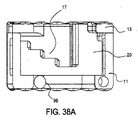
図1〜10Bは、本発明の特徴を有する選択的に拡張可能なケージ(SEC)、椎間インプラント10の例を示す。インプラント10は、通常、筐体11、筐体基部12、相互係止する上終板13、下終板14、筐体11内の内部空洞15、および一対のシリンダ16を含む。上側係止支持体17は、上終板13の下側に取り付けられ、逆向きの階段によく似た多段形状の下側支持面18を有する。直立した階段によく似た多段形状の上側支持面21を有する下側係止支持体20は、シリンダ16を包囲する。ピストン22は、上終板13の下面に固定される。シール部材23は、シリンダ16内に摺動可能に配置され、ピストン22上に装着される。下終板14の上面24には、ばね係止アクチュエータ26を部分的に受容する係止アクチュエータチャネル25が設けられる。筐体11の基部12は、下側係止支持体20の従属要素28または係止アクチュエータ伝達要素を摺動可能に受容し、ばね係止アクチュエータ26を部分的に受容するように構成される、弓形スロット27を有する。従属要素28は、ばね係止アクチュエータ26の順方向端部30に係合する。上終板13および取り付けられた上側係止支持体17が延長すると、付勢ばね係止アクチュエータ26によって印加される力に起因して下側係止支持体20がシリンダ16の周囲を回転するように、最初、ばね係止アクチュエータ26は圧縮構成にある。これにより、上終板13を延長構成に係止するように、下側係止支持体20の係止支持面21が上側係止支持体の支持面18に係合する。上側係止支持体17の支持面18および下側係止支持体20の支持面21は、インプラント10がいくつかの異なる拡張高さで係止され得るように、複数の段のある階段状になっている。上側係止支持体17の下側の階段状支持面18は、ピストン拡張の終了付近で増加がより少ない拡張を提供するように、上方向に徐々に高くなる蹴上げ高さ(整列面46)を備えてもよい。さらに、または代替として、下側係止支持体20の階段状支持面21は、同様の理由から、上方向に徐々に低くなる蹴上げ高さを備えてもよい。上側係止支持体17または下側係止支持体20の種々の蹴上げ高さが提供され得る。上側係止支持体17の一番下の階段状支持面18および下側係止支持体20の一番上の階段状支持面21は、より良好な支持を確実にするように種々の長さおよび幅で提供されてもよい。
1-10B illustrate an example of a selectively expandable cage (SEC)
図2を見ると分かるように、この実施形態では、2組の上側係止支持体17が上終板13に取り付けられ、2組の下側係止支持体20が存在するが、インプラント10を拡張された状態に係止するために、1組または2組より多くの上側および下側係止支持体が使用されてもよい。
As can be seen in FIG. 2, in this embodiment, two sets of upper locking supports 17 are attached to the
インプラント10は、脊椎の対向する椎体間に移植されるように構成され、これらの椎体間の骨の癒合を促進する。インプラント10は、図1では折り畳まれた構成または収縮構成で示され、図2では拡張構成のうちの一例で示されている。折り畳まれた状態では、最小の切開および最小の組織除去により、インプラント10を椎体間の空間内に容易に挿入することができる。一旦、その空間内に入ると、2つの対向する椎体に対してそれらを引き離すようにインプラント10を拡張し、それによって椎間腔に高さを復元することができる。これは、両方の椎体に対するインプラント10の安定した反発力を提供し、骨の癒合プロセスを最適化する。癒合プロセスはまた、身体への挿入の前および/もしくは後に、自家骨移植、骨成長を可能にするマトリックス、ならびに/または骨成長刺激物質で、内部空洞15を充填することによっても強化することができる。
The
インプラント10の個々の部品のさらなる詳細を図3、4A、および4Bに表す。筐体11内に位置するシリンダ16の内部で動作するシール部材23を支持するように構成されるピストン22は、上終板13の下側に取り付けられる。後により詳細に述べるように、シリンダ16が加圧されると、シリンダ16内で動作するシール23およびシール内に摺動可能に配置されるピストン22が垂直に変移させられ、筐体11の垂直上方に上終板13を移動させる。下側係止支持体20は、シリンダ16の外壁の周囲に位置する。上終板13が垂直に変移させられると、今度は取り付けられた上側係止支持体17を変移させ、下側係止支持体が付勢係止アクチュエータ26によって係止位置まで回転させられる。底板14の上面の弓形係止アクチュエータチャネル25および筐体基部12の弓形スロット27が、係止アクチュエータ26を筐体11に閉じ込める。
Further details of the individual parts of the
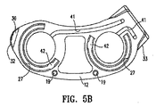
筐体11のさらなる詳細を図5Aおよび5Bに表す。筐体11は、外壁31と、筐体基部12に固定されたシリンダ16とを備える。外壁31は、遠位端上の先端ノーズ32および近位端上の送達ボス33を支持する。先端ノーズ32は、内側に方向付けられた側部テーパー面34ならびに上テーパー面35および下テーパー面36を有する。これらのテーパー面34、35、および36により、神経要素を通過して、椎体間に外傷なくインプラント10を挿入することができる。送達ボス33は、インプラント10を送達ツール(図示せず)に確実に取り付けることができる送達ツールアンカ37を含み、脊椎空間内への挿入に関して、2006年9月26日に出願された同時係属出願第11/535,432号、および2007年3月28日に出願された同時係属出願第11/692,800号に示される。送達ボス33はまた、シリンダ16の内部に加圧された液体を送達するために使用される圧力入力ポート38を含む。筐体11の外壁31はまた、筐体11の中心空洞15内への骨の内殖のための空間を提供し、骨の内殖プロセスの放射線撮像のために放射線透過性の開口部を提供する、側面開口部40を提供する。筐体基部12はまた、加圧された液体を圧力入力ポート38からシリンダ16の内部に送達する圧力チャネル41を含む。インプラント10の筐体基部12は、各シリンダ16ごとに独立した圧力チャネル41があるように描かれているが、他の実施形態は、2つ以上のシリンダ16に加圧された液体を送達するために1つ以上の分岐した圧力チャネルを含むことができる。前述したように、筐体基部12はまた、係止アクチュエータ26を保持して誘導する係止アクチュエータスロット27を有する。係止アクチュエータスロット27は、筐体基部12内の係止アクチュエータスロット27および下終板14の係止アクチュエータチャネル25によって画定されるチャネル内への係止アクチュエータ26の挿入を可能にするように、幅のより広い部分である係止アクチュエータ開口部42を含む。筐体基部12はまた、任意選択の整列孔9を介して下終板14を筐体11に整列させる任意選択の整列ボス19を含む。
Further details of the
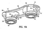
図6Aおよび6Bは、上終板13および下側係止支持体20のさらなる詳細を示す。2組のピストン22および上側係止支持体17は、接続部材または支柱44によって連結される。ピストン22は、シール23が装着されるシールボス45を有する。上側係止支持体17は、段のある下側支持面18と、蹴上げ面または整列面46とを有する。上側係止支持体17の段のあるまたは階段状の支持面18は、下側係止支持体20の段のあるまたは階段状の支持面21に係合する。上側係止支持体の整列面46は、下側係止支持体20の整列面47に係合するように構成される。上側係止支持体17に係合したときに下側係止支持体20が過回転するのを防止するように、下側係止支持体20の一番上の支持面は、上側係止支持体の一番下の整列面46に係合する係止支持停止部50を有する。また下側係止支持体20の底面は、係止アクチュエータ26から下側係止支持体20に作動力を伝達するために、ばね係止アクチュエータ26の順方向端部30に係合する係止アクチュエータ伝達要素28を有する。
6A and 6B show further details of the
図7〜10Bは、筐体11を取り外したインプラント10の選択的な拡張係止の順序の詳細を示す。上側係止支持体17の支持面18が下側係止支持体20の支持面21上に載置された折り畳まれた構成を図7に示す。係止アクチュエータ26は、係止支持体の整列面が接触する方向にそれらを付勢するように、従属要素または係止アクチュエータ伝達要素28に係合するばね等の付勢要素である。よって、1つの例示的な実施形態において、下側係止支持体17の整列面47は、上側係止支持体17の整列面46に押し付けられる。係止支持停止部50は、上終板13上の下側係止停止逃げ部52(図6Aにおいて最もよく示される)内に適合する。シリンダ16が加圧されると、ピストン22が上終板13および取り付けられた上側係止支持体17(直線の矢印)を持ち上げて、上側係止支持体17の支持面18を支持面21から移動させ、上側整列面47を越えるように下側整列面46を移動させる。上側係止支持体17の整列面46が下側係止支持体20の整列面47を通過すると、係止アクチュエータ伝達要素28に係合する係止アクチュエータ26(この実施例では、圧縮されたコイル状ばね)が、下側係止支持体20を回転させる(図8Bおよび9Bの曲線の矢印)。回転する下側係止支持体20の支持面21は、下側係止支持体20の整列面47が上側係止支持体17の整列面46の次のレベルに係合するまで、持ち上げられた上側係止支持体17の支持面18の次に低いレベルに移動する。次いで、下側係止支持体20および上側係止支持体17は、この拡張レベルで上終板13を係止する。図10Bに示すような最高レベル(またはその間のどこか)に達するまで、このプロセスは、各係止レベル(図8A、8B、9A、9Bおよび10A)でこれを繰り返す。この最高レベルでは、係止アクチュエータ26が係止アクチュエータ伝達要素28に係合し、下側係止支持体20が回転させられて、上側係止支持体17の一番下の整列面46が下側係止支持体20の一番上の支持面21の係止支持停止部50に係合する。この最高係止レベルでは、上側係止支持体17の最も低い支持面18および最も高い支持面21のみが係合され、係止支持の全てを提供する。図10Aおよび10Bを見ると分かるように、上側係止支持体17の最も低い支持面18および下側係止支持体20の最も高い支持面21は、これら2つの面が係合された場合にのみ十分な支持材料を提供するように、他の支持面よりも幅広くてもよい。
7-10B show details of the sequence of selective expansion locking of the
図11Aおよび11Bは、係止アクチュエータ26の動作を示す。この実施形態において、ばね係止アクチュエータ26は、下側係止支持体20の下でアーチ状に圧縮されている。ばね係止アクチュエータ26の一方の端部は筐体11(図示せず)によって拘束され、他方の端部は係止アクチュエータ伝達要素28と係合する。ピストン22の延長によって、上側係止支持体17の下側整列面46が下側係止支持体20の上側整列面47の上に持ち上げられると、係止アクチュエータ26が係止アクチュエータ伝達要素28を押して、上から見て時計回りの方向(矢印)に下側係止支持体20を回転させる。これまで記載した本インプラントの実施形態において、1組より多くの支持体が存在する場合は、段のある上側および下側支持面18および21の角度方向は様々であってもよいことに留意されたい。図3に示すように、近位の下側支持面21は、上から見て時計回りに配向され、遠位の下側支持面21は、反時計回りに配向されている。この反対の配向が、インプラントに印加される回転力に強化された係止支持を提供する。
11A and 11B illustrate the operation of the locking
代替の係止アクチュエータ26aを、捩りばねとして図11Cに示す。この係止アクチュエータ26aは、下側係止支持体20に固定された拘束タブ53および筐体11aに固定された拘束タブ54を有する。図11Aおよび11Bに示される圧縮ばねが、下側係止支持体20aに力を印加して回転させると同時に、図11Cの捩りばねも同じことを行う。延長ばねも、係止アクチュエータ26aと等しく動作する。ばねアクチュエータは、ステンレススチール、ニチノール、チタン、または好適なポリマー等の適切な生体適合性材料から作成することができる。係止アクチュエータは、ばねに限定されない。下側係止支持体20を作動させるために、リニア駆動、外部から作動される引張部材、ウォームギア、バルーンまたはベローズ等の膨張部材、磁石、マイクロモーター等の回転駆動、超弾性形状記憶要素等を含むが、これに限定されない、多様な機構を使用することができる。
An alternative locking actuator 26a is shown in FIG. 11C as a torsion spring. The locking actuator 26a has a restraining
図12A〜12Cは、上述した下側係止支持体20の変形例を示す。図12Aでは、上述した2組ではなく、上側支持面21a、上側整列面47a、および係止支持停止部50の3組が存在する、3つで1組の係止支持体20aが示されている。この3つで1組の下側係止支持体20aは、2組の設計よりも優れた2つの利点を有する:1)2つの支持カラムがインプラント10を拡張状態に係止するのではなく、3つの支持カラムが存在するため、より安定した係止を形成する、2)3つで1組の下側係止支持体20aは、各係止レベルのために移動または回転する量が大分少なくてよい。これにより、各ステップで必要とされる係止力を達成するためにばねにかかる負担が少ないため、この最後の利点は、係止アクチュエータがばね係止アクチュエータ26等のばねである場
合に重要である。各下側係止支持カラムは、対応する上側係止支持カラム(図示せず)を有する。上側支持面21および下側支持面18は、2組または3組の面に限定されない。1組を含む任意の数の組の支持面が用いられてもよい。
12A to 12C show a modified example of the
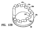
図12Bは、指状の下側係止支持体20bを示す。指状係止支持体20b上の指状上側支持面21bの各々は、指状停止部50bと対になっており、上側係止支持体(図示せず)の一致する指状支持面および停止部が対になると、指状支持面21bが上側係止支持体の指状支持面に対して移動するのを阻止し、指状下側支持面を最初に指状停止部50bの上まで上昇させずに、インプラント10bを係止解除する。この設計は、係止機能の強化をもたらす。
FIG. 12B shows a finger-like lower locking support 20b. Each of the finger-like upper support surfaces 21b on the finger-like locking support 20b is paired with a finger-
一般に、係止されたインプラントにおける垂直支持を最大化するために、下側支持面18および上側支持面21は水平である。しかしながら、図12Cに示される係止支持体20cは、インプラント10cを係止解除するように上側係止支持体が回転され得る前に、上側係止支持体(図示せず)上の一致する傾斜した下側支持面が、傾斜した上側支持面21cの上まで上昇させられる必要がある、水平に対して勾配を有する傾斜した支持面21cを提供することによって係止機能の強化をもたらす。
In general, the
図12Aおよび12Cは、種々の長さの係止アクチュエータ伝達要素または従属要素28を示す。係止アクチュエータ伝達要素28は、係止アクチュエータ伝達要素28と係止アクチュエータのスロット27との間にどのくらいの係合が所望されるかによって、異なる長さであり得る。係止アクチュエータ伝達要素28は、下側係止支持体20を筐体11の係止アクチュエータのスロット27に垂直に拘束する1つ以上の伝達要素タブ29aおよび29cを含む。上述したより幅の広い係止アクチュエータ開口部42は、係止アクチュエータ伝達要素28が係止アクチュエータ開口部42と整列する回転位置で、伝達要素タブ29aおよび29cを有する係止アクチュエータ伝達要素28を筐体基部12の係止アクチュエータのスロット27内に挿入することを可能にする。他の回転位置では、伝達要素のタブは、より幅の狭い係止アクチュエータのスロット27の側面上の側方延在部49(図4Bに示される)によって拘束される。このようにして、係止アクチュエータ伝達要素28は、係止アクチュエータ26から下側係止支持体20に力を伝達する機能と、下側係止支持体20を筐体11に拘束する機能の両方を提供する。この後者の機能は、上側係止支持体17がピストン22によって上昇されたときに、下側係止支持体20を上側係止支持体17とともに上昇することにより、付勢ばね係止アクチュエータ26によって形成される下側整列面46と上側整列面47との間の摩擦力を阻止する。
FIGS. 12A and 12C show various lengths of locking actuator transmission elements or
係止アクチュエータ伝達要素28の代替として、図12Bに示す実施形態は、係止アクチュエータ誘導チャネル80を表している。この係止アクチュエータ誘導チャネル80は、係止アクチュエータ26から下側係止支持体20に作動力を伝達する引張部材(図示せず)に係合する。引張部材は、ポリマーまたは天然材料でできた縫合糸、金属ケーブル、プラスチックまたは金属のロッド等の多数の既知の要素であり得る。
As an alternative to the locking
図13Aおよび13Bは、本発明の特徴を具体化するインプラント110の代替設計を示す。インプラント110は、遠位ピストン122aおよび近位ピストン122bの独立した作動を有する。2つのピストン122aおよび122bは、インプラント110の各側の独立した上昇および係止を可能にする、関節動作する上終板113によって相互接続される。このインプラント110の両端における独立した上昇および係止は、その間の横方向の高さが不均一な椎間終板にインプラントを一致させることが可能である。さらに、この独立した上昇および係止は、椎骨終板の間に様々な横方向の高さを形成するためにインプラント110を使用することを可能にし、それは脊椎における脊柱側弯症を補うのに有用であり得る。
13A and 13B show an alternative design of
インプラント110は、その中に位置する代替の送達ツールアンカ160を有する筐体111および代替の圧力入力ポート137とを有する。本発明の範囲から逸脱することなく、本デバイスの実施形態のいずれかとともに種々のアンカ設計または圧力ポートを使用することができる。係止および係止解除アクセスポート138もまた、この筐体111上に位置する。これらのポートは、上側係止支持体117の下で下側係止支持体120を移動させてピストン122bおよび関節動作する終板113を拡張位置に保持するだけでなく、下側係止支持体120を上側係止支持体117から離して移動させ、ピストン122bおよび関節式の終板113が折り畳まれて筐体110内に戻ることを可能にするように、下側係止支持体120を作動させるためにインプラント110の外で操作することができる、係止および係止解除機構(図示せず)を誘導するために使用される。この後者の動作は、椎間腔からインプラント110を除去するため、または椎間腔内にインプラントを再配置するために望ましい可能性がある。これらに限定されないが、縫合糸および金属ケーブルを含む引張部材、金属またはポリマーのロッド等の圧縮部材、加圧された液体、回転駆動、超弾性形状記憶要素等の、種々の係止/係止解除機構を本発明とともに使用することができる。
The
図14A〜14Cは、本発明の実施形態の特徴を具体化するさらに別の代替インプラント210を表す。インプラント210は、接触上板213上のピストン捕捉板270および回転ピストン222ab上のピストンヘッド318を介して、回転ピストン222に別個にかつ自由に接続する接触上板213を有する。回転ピストン222abはまた、支持面218および整列面246を有する上側係止支持体217を内側に含む。シール223は回転ピストン222ab上に取り付けられ、シール223および回転ピストン222abは、筐体211上に位置する内部シリンダ216内に適合する。内部シリンダ216は、支持面221および整列面247を有する下側係止支持体220、ならびに下側保持フィーチャ273を有する。筐体211はまた、1つ以上の圧力入力ポート238を含む。
14A-14C illustrate yet another
使用の際は、インプラント210が折り畳まれた状態で椎体間の空間内に挿入され、シール(複数可)223および回転ピストン(複数可)222abを内部シリンダ(複数可)の外に持ち上げるように、液圧が圧力入力ポート(複数可)238を通って内部シリンダ(複数可)216に送達され、それによって接触上板213を持ち上げ、インプラント210を拡張する。一旦、回転ピストン222abが持ち上げられ、上側係止支持体217の下側整列面246が下側係止支持体220の上側整列面247を通過すると、アクチュエータ(図示せず)が回転ピストン222abを回転させ、上側係止支持体217の下側支持面218が下側係止支持体220の上側支持面221の上に移動させられ、それによってインプラント210を拡張構成に係止する。アクチュエータは、ユーザからインプラント210内へ、接触上板213上の係止および係止解除アクセスポート238を通ってピストンヘッド271まで延在する、縫合糸またはケーブル等の1つ以上の引張部材であってもよい。ピストンが延長構成にあるときに1つ以上の引張部材に張力を印加してピストンヘッド271を回転させることで、上側係止支持体217の支持面218が下側係止支持体220の支持面221の上に移動させられ、それによってインプラント210を係止する。代替として、またはインプラント210を拡張構成に係止するために張力を印加することに加えて、1つ以上の引張部材に張力を印加することによりピストンヘッド271を回転させることで、下側支持面218が上側支持面221から離れて移動させられ、それによってインプラント210を係止解除し、回転ピストン22ab2を内部シリンダ216内に戻すことが可能であり、インプラント210が再び折り畳まれた構成となる。
In use, the
図15は、前の実施形態に類似する筐体311、上終板313、およびピストン322を有する本発明の特徴を具体化する代替のインプラント設計310を示す。このインプラント310は、インプラントの中央部に上側係止支持体317および下側係止支持体320を有する。上述したように従属要素(図示せず)によって、上側係止支持体317が上終板313に固定され、下側係止支持体320が基部314に固定され、前の実施形態におけるように移動させられる。
FIG. 15 shows an
図16は、前の実施形態に類似する筐体411、上終板413、および中央に位置するピストン422を有する、本発明の特徴を具体化する代替のインプラント設計410を示す。このインプラント410は、中央に位置するシリンダ416およびピストン422の遠位および近位に上側係止支持体417および下側係止支持体420を有する。上側係止支持体417は上終板413に固定され、下側係止支持体420は基部412に固定され、上述したように従属要素(図示せず)を介して前の実施形態におけるように移動させられる。
FIG. 16 shows an
図17は、一対のピストン522を有し、基部512上のラチェット520と、上終板513に枢動可能に取り付けられ、かつそこに従属する歯止め517を含む係止支持システムを有する、別の代替インプラント510を示す。ピストン522の拡張が、歯止め517の自由端518をラチェット521の窪み520に係合させ、上終板513を延長構成に係止する。
FIG. 17 includes another pair of pistons 522 and includes a ratchet 520 on the
図18は、図17に示すものと類似する別の代替のインプラント設計610を示す。この実施形態では、インプラント610を係止するために、歯止め617とラチェット621との間により大きな効果的な接触を提供するように、歯止め617の自由端が複数の歯618を有する。
FIG. 18 shows another
図19は、本発明の特徴を具体化するインプラント710の別の実施形態の断面図である。この実施形態では、ピストン722は、支持面718で終端する少なくとも1つのカンチレバー延在部を有する上側係止支持体717によって包囲されている。支持面718は、筐体711の内壁に位置する窪んだ支持面721によって捕捉されている。一旦、ピストン722が上向き方向に拡張されると、上側係止支持体717の支持面718が窪んだ支持面721に係合し、インプラント710を所定の場所に係止する。上側係止支持体717は、ピストン722および筐体711に対して回転させることができ、必要に応じてインプラント710を係止解除してピストン722を低くするように、支持面718を支持面721から係脱させる。代替として、インプラント710は、カンチレバー延在部を押して支持面718を支持面721から係脱させるように、上側係止支持体制約部775を上側係止支持体717に対して回転させることによって係止解除することができる。
FIG. 19 is a cross-sectional view of another embodiment of an
図20A〜31は、延長構成にあるピストン等の延長可能な部材を係止するための種々の好適な手段を示す。図20A、20B、21A、21B、および22〜31は、下側係止支持体および上側係止支持体の変形例を示す。これらの変形例の各々において、上側係止支持体の支持面に係合する下側係止支持体の支持面が存在する。 20A-31 show various suitable means for locking an extendable member, such as a piston, in an extended configuration. 20A, 20B, 21A, 21B, and 22-31 show variations of the lower locking support and the upper locking support. In each of these variations, there is a support surface for the lower locking support that engages the support surface for the upper locking support.
図20Aおよび20Bにおいて、支持面818は、上側係止支持体817に設定された溝を備える。下側係止支持体820は、これらの図面には示されていないインプラントを係止するために、上側係止支持体817に向かって前進し(図20Aの矢印によって示される)、その上側支持面821で溝のうちの1つに係合するように構成される、U字形状のトングである。下側係止支持体を係脱させ、インプラントを係止解除するために、下側係止支持体820が溝から撤退される(図20Bの矢印によって示される)。
In FIGS. 20A and 20B, the
図21Aに示す変形例において、下側係止支持体920は、円筒状の、平坦な側面のある上側係止支持体917が下側係止支持体920(矢印)を通って通過できるように成形される、上側係止隙間開口部970を有する板である。図21Bに示すように、下側係止支持体920は、一旦、所望の場所に位置付けられると、下側係止支持体920の支持面を上側係止支持体917の支持面918と係合させるように、約90°(矢印)回転させることができる。上側係止支持体917および噛合する下側係止支持体920の上側係止隙間開口部970の形状は、図21Aおよび21Bに示される輪郭に限定されず、また、係止作動も、要素のうちの1つの90°の回転に限定されるものではなく、1つの構成において通過を許容する任意の数の形状まで異なり得るが、要素のうちの1つが別の構成に移動させられる場合は制約される。
In the variation shown in FIG. 21A, the
図22において、上側係止支持体1017は、支持面1018を形成するために切り抜かれた切欠きを有するシリンダである。下側係止支持体1020は、下側支持面1021のための歯止め1071を有する枢動ピン1070である。図示する構成において、支持面は、上側係止支持体1017がインプラントの拡張可能な部材とともに上昇することを可能にし、また上側係止支持体が落下するのを防止するように、矢印1072によって示されるように付勢されている。これにより、上側係止支持体1017の次の支持面1018が下側係止支持体1020の支持面1021に係合したときに、デバイスが各レベルで係止することが可能となる。本発明の特徴を有するこの変形例では、下側係止支持体1020の枢動ピン1070を、支持面1021を支持面1018から係脱させるように上側係止支持体1017から離して移動させることによっても、上側係止支持体1017を下降させることができる。
In FIG. 22, the
図23は、下側係止支持体1120が、上側係止支持体1117に位置する支持面1118に係合する(矢印)ように構成されるピンである、本発明の特徴を有するさらに別の実施形態を示す。下側係止支持体1120は、この図に示されるように、上側係止支持体1117の全厚さに係合する必要はなく、また、支持面1118も、上側係止支持体1117の厚さ全体にわたって延在する必要はなく、インプラントを所定の位置に係止するのに十分である上側係止支持体1117の任意の位置に係合することができる。この実施形態はまた、ピン1120および一致する支持面1118の種々の形状を許容する。
FIG. 23 illustrates yet another feature having the features of the present invention in which the
図24において、下側係止支持体1220は、2つの枢動顎部1270を有する把持部であり、その端部は支持面1221を有する。上側係止支持体1217は、支持面1218を有する一連の切欠き1271を有する。圧縮ばね(図示せず)等の係止アクチュエータは、把持部基部の延在部1273に力を印加して(矢印1272で示されるように)、デバイスを係止することができる。本発明の特徴を有するこの変形例は、上側係止支持体1217が上向きに移動することを許容するが、その下向きの運動を阻止する。上側係止支持体1217の下向きの運動は、把持部基部の延在部1273にかかる力を逆向きにすることにより可能になる。
In FIG. 24, the
本発明の特徴を具体化する係止システムの全てが、上側係止支持体の支持面が下側係止支持体の支持面上に直接係合することを必要とするわけではない。図25〜32に示すようなデバイスを係止するために、摩擦支持が形成されてもよい。 Not all locking systems embodying features of the present invention require that the support surface of the upper locking support engage directly on the support surface of the lower locking support. A friction support may be formed to lock the device as shown in FIGS.
図25において、上側係止支持体1317は、支持面1318として1つ以上の平坦な面を有する。下側係止支持体1320は、支持面1318に係合して負荷(矢印)を支持する支持面1321を有する、1つ以上の枢動する歯止めを有する。
In FIG. 25, the
図26において、上側係止支持体1417は、巻きつけられた下側係止支持体1420の内径上で支持面1421によって把持される外側支持面1418を有する。この下側係止支持体1420は、その自由な状態において上側係止支持体1417を把持し、その端部1470のうちの1つ以上に図示されるように力(矢印)が印加されると、上側係止支持体を解除してばねの内径を増加させる、捩りばねであり得る。その反対も可能であり、その場合は、下側係止支持体1420は、その自由な状態において、内径内での上側係止支持体1417の運動を許容する。内径を減少させるように端部1470に引張力が印加されると、下側係止支持体が上側係止支持体1417の支持面1418を把持して、インプラントを係止する。
In FIG. 26, the
図27Aおよび27Bは、傾斜したワッシャータイプのデバイスとして説明することのできる別の変形例を示す。下側係止支持体1520は、図27Aに示すように、上側係止支持体1517の相対的な運動を許容する上側係止隙間開口部1570を有する板である。下側係止支持体1520が図28Bに示すように傾斜している場合、上側係止隙間開口部1570の縁部は、それを下側係止支持体1520に相対的に係止する上側係止支持体1517の外側表面である上側支持面1518に係合する、下側支持面1521を備える。
27A and 27B show another variation that can be described as a tilted washer-type device. The
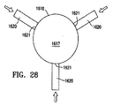
本発明の把持係止のさらに別の変形例を図28に示す。この変形例において、下側係止支持体1620は、デバイスを所定の位置に係止するための摩擦を生じさせるように、上側係止支持体1617の支持面1618に対して押し付けられるように構成される支持面1621を有する、1つ以上の顎部を備える。
FIG. 28 shows still another modified example of the gripping and locking of the present invention. In this variation, the
図29は、上で詳述されるように旋回軸および歯止めを備える下側係止支持体1720を示す。歯止めの端部は、上側係止支持体1717の上側支持面1718に係合する下側支持面1721を備える。この実施形態において、上側係止支持体1717は、拡張する要素(図示せず)によって反時計回りに回転させられる。この回転が、今度はインプラントを拡張するピストン1722を持ち上げる。このようにして、上側係止支持体1817は、拡張するにつれて、下側係止支持体1720に係合してインプラントを係止するための上昇機構内に組み込まれる。
FIG. 29 shows a
図30は、上側係止部材1817および下側係止部材1818が、前の実施形態の弓形形状ではなく直線的な形状を有することを除いて、図1に示すインプラントと類似する、さらに別の代替インプラント1810を示す。インプラント1810は、通常、筐体1811、上板1813、下板1814、ピストン1822、およびシリンダ1816を有する。上側係止部材1817は支持面1818を有し、下側係止部材1820は支持面1821を有する。インプラント1810は、係止アクチュエータ(図示せず)を有する。
FIG. 30 shows a further alternative, similar to the implant shown in FIG. 1, except that the
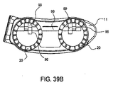
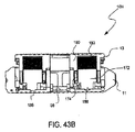
図31A〜31Gは、支持面1918を有する溝1970を備える上側係止部材1917と、係止面1921を備える下側係止部材1920とを有する、本発明の特徴を具体化する別のインプラント1910を示す。下側係止部材1920は、両方の上側係止部材1917の外側を取り囲み、溝1970の中に位置するように構成されるワイヤフォームである。係止アクチュエータ(図示せず)による下側係止部材1920の拡張(図31Bの矢印)により、下側係止部材1920が溝1970の外に引き出され、インプラントの拡張とともに上側係止部材1917を上昇させる。この下側係止部材1920の拡張の解除(図31Aの矢印)により、下側係止部材1920が溝1970内に戻り、インプラント1910を係止することが可能となる。
FIGS. 31A-31G illustrate another
図31Gは、支持面1918aを有する溝1970aを備える上側係止部材1917aと、係止面1921aを備える下側係止部材1920aとを有する、本発明の特徴を具体化する代替インプラント1910aの詳細を示す。下側係止部材1920aは、両方の上側係止部材1917aの外側を取り囲み、溝1970aの中に位置するように構成されるワイヤフォームである。上側係止部材1917a上に圧縮力または下向きの力(白抜きの矢印)が存在するとき、支持面1918aが支持面1921a上で係止し、インプラント1910aを係止する。上側係止部材1917aの上向きの力または延長(塗りつぶした矢印)は、下側係止部材1920aを係脱面1919a上に動かして溝1970aから逸脱させ、インプラント1910aの拡張とともに上側係止部材1917aを上昇させる。 FIG. 31G shows details of an alternative implant 1910a embodying features of the present invention having an upper locking member 1917a with a groove 1970a having a support surface 1918a and a lower locking member 1920a with a locking surface 1921a. Show. The lower locking member 1920a is a wire form that surrounds the outside of both upper locking members 1917a and is positioned in the groove 1970a. When compression force or downward force (open arrow) is present on the upper locking member 1917a, the support surface 1918a locks on the support surface 1921a and locks the implant 1910a. The upward force or extension (filled arrow) of the upper locking member 1917a moves the lower locking member 1920a onto the engagement / disengagement surface 1919a to deviate from the groove 1970a, causing the upper locking member 1917a to expand with the expansion of the implant 1910a. Raise.
本発明のさらなる態様において、上述したようなピストン/シリンダおよび係止配置が、延長可能な骨アンカを配備するために使用されてもよい。例えば、図32Aおよび32Bに示すような円錐状の骨係合アンカ60を有するインプラント10Aは、インプラント10と関連して上述したような、例えば、図2、3、および4Bに示されるような、ピストン22およびシリンダ16とともに構築されてもよい。インプラント10Aは、上述したように筐体11を有し、骨成長刺激物質のための内部空洞15等の、以前に記載した他の特長を含むことができる。しかしながら、この実施形態では、上側相互係止終板13の代わりに、2つのピストン22が、それぞれ、円錐状の骨係合アンカ60とともに終端する。鋭利な先端62を含む骨係合アンカは、椎体に係合するための表面を形成する。
In further aspects of the invention, a piston / cylinder and locking arrangement as described above may be used to deploy an extendable bone anchor. For example, an
図32Aに示すように、骨係合アンカ60は、インプラント10Aの挿入を容易にするように、筐体11内で収縮構成にある。上述したような油圧式の作動を使用して、骨係合アンカ60は、図32Bに示されるような延長構成に移動され、骨内で係合して固着するように、少なくとも先端62が筐体11を超えて延長する。骨係合アンカがしっかりと骨内に係合された状態を維持することを確実にするために、インプラント10と関連して上述したような、例えば、図6A〜12Cに示されるような、多段形状の上側および下側係止支持体17、20を含む係止機構が、アンカ60を延長構成に支持するために設けられる。この配置を用いると、延長および係止されたアンカ60が、インプラントを所定の位置に維持するのに役立つ。
As shown in FIG. 32A, the
図33A〜Cに示すように、本発明による骨係合アンカには、種々の代替例が可能である。例えば、図33Aのインプラント10Bは、突起60Aおよび羽根60Bとして形成される骨係合アンカを含む。羽根60Bは、配備後に、挿入経路に沿った動きを阻止するのに特に効果的であり得る。この場合、羽根60Bの長さは、矢印Aによって示される方向に整列される。これは、移植の方向(矢印B)と実質的に直交しており、その方向への運動に抵抗する。図33Bに示されるインプラント10Fは、さらに可能な変形例を含む。この実施形態において、骨係合アンカは棘状突起60Cとして形成される。突起のシャフトに沿った棘部61が、アンカの軸に沿ってインプラントを組織から移動させる傾向にある力に抵抗する(後述するネジ山付きアンカも同様にこの力に抵抗する)。またインプラント10Fには、横方向に配向された組織内に固着するための横方向の骨係合アンカ63も含まれる。例示される実施形態において、横方向のアンカ63は、単純な突起60Aを含む。横方向のアンカ63は、図示されるように構成要素が横方向に配向されることを除いて、本出願の他の箇所に記載されるのと同じ様式において、同じ構成要素(すなわち、ピストン、シリンダ、係止機構等)で形成される。この横方向の実施形態において骨アンカ構成要素に支持を提供するために、筐体11は、内部空洞15を2つの部分に分割する中央部材11Aを含む。インプラント10Bおよび10Fの構成において、アンカ部材が骨内に完全に受容されると、ピストン22の上部もまた骨係合面になることができる。図33Cは、直交するのではなく、筐体11から斜めに延在するアンカ65を含む、さらなる代替インプラント10Gを示す。この斜めの配置は、左右の回転力(例えば、患者/脊椎が横に曲がるとき)および拡張力に抵抗するのに役立つ。ここでも同様に、斜めに延在するアンカ65は、斜めの配向を除いて、本明細書に記載される他の骨係合アンカと本質的に同じである。ここでは、上終板66に、突起が通過するための孔68が設けられる。一般に、本発明の実施形態による骨係合アンカは、硬い骨組織内に延長するその能力を強化するために、油圧液によって生じるピストンにかかる力が、小さいアンカ終端部で比例的にかなり大きな力となるように、ピストンの直径サイズに対して比較的小さい終端部(例えば、先端部62)を有するべきである。また、当業者は、本明細書に記載される骨係合要素、例えば、突起、羽根、棘部等の種々の特徴は、本出願の図に示される例示的な組み合わせに加えて、任意の所望の組み合わせで組み合わされてもよいことを理解するであろう。
As shown in FIGS. 33A-C, various alternatives are possible for the bone engaging anchor according to the present invention. For example, the
図34Aおよび34Bに示される別の代替実施形態において、インプラント10Cは、ネジ山付き部材64を骨係合アンカとして含む。インプラント10Cもまた、アンカ等の骨係合面がインプラントの反対側から延在する、さらなる代替例を示す。この例示的な実施形態において、相互係止終板13は、一体型上終板66に置き換えられている。ネジ部材64が通過するための孔68が設けられる。当業者は、必要に応じて孔68が位置してもよく、例示する実施形態において、一方は終板66に、他方は下終板14にあることを理解するであろう。
In another alternative embodiment shown in FIGS. 34A and 34B, the implant 10C includes a threaded
ネジ山付き骨係合アンカ64は、ピストン22から外側に延在する。ピストンが延長されたときにネジ山付きアンカを回転させて骨内に入れるために、筐体11の内壁には、ピストン22と協動して対応するネジ山71と噛合するネジ山面70が設けられる。前述したように、シール23は、ピストン22とシリンダ16との間で作動して、油圧液の漏洩を防止する。前の実施形態について記載したように、シリンダ内で液体が加圧されると、ピストンは、延長されるだけでなく、ネジ山面70と71との間の係合によって円運動で駆動される。したがって、ネジ山付きアンカ64は、延長されるにつれて隣接する骨内に推進される。
A threaded
ここでも同様に、例えば、図6A〜12Cにおいて以前に説明および示した係止機構が、骨係合アンカが骨から離脱するのを防ぐために用いられてもよい。図34Aおよび34Bの断面図において、上側および下側係止支持体17、20は、ピストンおよびシリンダの外側周辺で眼に見える。代替として、ネジ山の付いた部分の深さおよびピッチによっては、別個の係止機構の使用が必要ではない可能性がある。当業者は理解するように、アンカが後退するのを防ぐのに、ネジ山構成単独で十分である可能性がある。 Again, for example, the locking mechanism previously described and shown in FIGS. 6A-12C may be used to prevent the bone engagement anchor from detaching from the bone. In the cross-sectional views of FIGS. 34A and 34B, the upper and lower locking supports 17, 20 are visible around the outside of the piston and cylinder. Alternatively, depending on the depth and pitch of the threaded portion, the use of a separate locking mechanism may not be necessary. As those skilled in the art will appreciate, a thread configuration alone may be sufficient to prevent the anchor from retracting.
図35Aおよび35Bは、記載されるような係止機構が、入れ子式骨係合面を所定の位置に固定するのに用いられる、本発明のさらなる態様を示す。本明細書で使用される場合、入れ子式とは、基部と骨係合部材との間に少なくとも1つの中間部材を含む、入れ子になった延長可能な部材を指す。 FIGS. 35A and 35B show a further aspect of the invention in which a locking mechanism as described is used to secure the telescoping bone engaging surface in place. As used herein, telescoping refers to a nested extendable member that includes at least one intermediate member between a base and a bone engaging member.
最初に図35Aを参照すると、インプラント10Dは、実質的に平面である骨係合部材72を有する。よって、骨係合部材72は、インプラント10の骨係合部材に類似するが、相互係止終板13なしで個別に作動される。ピストン/シリンダの配置もまた、以前に記載したものと類似するが、ここでは、上側ピストン74が中間ピストン80内に受容される。ピストン22について以前に記載したように、中間ピストンが、今度はシリンダ16に受容される。上側ピストン74は、上側ピストンシール76によって、中間ピストンの中間シリンダ78に対してシールされる(図35Bを参照のこと)。
Referring initially to FIG. 35A, the
入れ子式の骨係合部材72は、先に記載した実施形態と同様の様式で係止機構によって固定されるが、上側ピストンのための上側係止支持体82が追加される。中間ピストン80は、以前に記載したように、上側係止支持体17および下側係止支持体20によって支持される。上側係止支持体82は、上側および下側係止支持体84、86を含む。よって、上側ピストン74は、上側係止セットの上側係止支持体84に固定される。上側係止セットの下側係止支持体86は、下側係止セットの上側係止支持体17の頂上部に取り付けられる。先に記載した実施形態と1つ違う点は、アクチュエータ26によって下側係止セットとともに回転させることができるので、上側係止セットに別個のばねアクチュエータ26が必要とされないことである。
The telescoping
図35Bに示すように、インプラント10Eは、上側骨係合面88の平面部分は、中央で、円錐状アンカ90とともに効果的に環状である、さらなる変形例を含む。骨係合アンカを含む本発明の実施形態の利点は、油圧管路のインプラントとの比較的小さな接続部を使用して、比較的高い力でインプラントの長軸(すなわち、挿入軸)から横方向に延長されるアンカの能力を含む。これは、硬い骨組織内にアンカを延長するために、より大きなツールまたは非油圧式の延長力を必要とするインプラントへのより大きなアクセスまたはより大きな接続部を必要とする他の方法より優れた利点である。
As shown in FIG. 35B, the
以前に記載した本発明の実施形態は、上終板を下終板から離して上昇させるために使用される機構として、加圧された液体を用いて拡張されるシリンダ16およびピストン22を含んでいたが、本発明の実施形態は、そのような上昇機構のみに限定されない。図36A〜Cにおいて、一対のベローズ92が以前に記載した一対のピストンおよびシリンダに取って代わるインプラント10Fを備える本発明の代替実施形態が示される。ベローズ92の一方の端部は筐体11に、そして他方の端部は上終板13に取り付けられる。圧力入力ポート38を介して加えられる加圧された液体は、ベローズのオリフィス94を通ってベローズ92の内部に方向付けられ、ベローズを拡張させる。拡張するベローズが、上終板13を筐体11から押し離し、以前に記載したように、デバイスを拡張構成に係止するように下側係止支持体20が回転させられる。ベローズ92は、ステンレススチールの316シリーズ、チタンもしくはチタン合金、コバルトクロム合金、または移植可能なポリマー材料等の、任意の生体適合性材料で作製することができる。ベローズは、図36A〜Cに示すようなアコーディオン状の折り目のついた構成であってもよいか、または、折り畳まれた構成で筐体および係止支持体の内側に適合でき、筐体11から所望の量だけ離して上終板13を上昇させるように加圧されると十分に拡張できる、任意の他の規則的または不規則的な構成であってもよい。下側係止支持体20および上側係止支持体17は、ベローズ92に閉じ込め構造を提供し、それにより不規則なベローズ構成の使用が可能になる。図36Aおよび36Bに示されるようなベローズの配置を用いると、上昇量は、シリンダおよびピストンの場合のように、折り畳まれたシリンダおよびピストンが上に重なる量には限定されない。
The previously described embodiments of the present invention include a
他の例示的な実施形態は、拡張のために加圧された液体の使用に依存しない。例えば、図37Aおよび37Bは、代替の回転するカム上昇機構93を示す。カム上昇機構93は、実質的に曲線であるカム表面95および実質的に平坦である上表面97を有するカム96、回転シャフト98、ならびにシャフト支持体99を含む。カム96は、回転シャフト98に取り付けられ、シャフト98は、シャフト支持体99によって支持され、またその中で回転する。この機構を使用するインプラント10Gにおいて、シャフト支持体99は筐体11の内側に固着され、シャフト98の回転(曲線矢印によって表される)は、曲線的なカム表面95を上終板13の底部に対して回転させ、図38A〜38B、39A〜39B、および40に示されるように、上終板13を筐体11から離して移動させる。カム96の形状が、可能な上昇量およびカムの回転量に対する相対的な上昇量の両方を決定する。カムは、図に表される90度の回転によって限定されない。本発明の範囲から逸脱することなく、最低10度から最高355度までの任意の量によって回転させられるカムの任意の形状が可能である。シャフトの回転は、後により詳細に記載されるように、いくつかの手段によって達成可能である。インプラント10Gのための下側および上側係止支持体20および17とともに、上昇機構としてカム上昇機構93を使用することは、上昇機構が、初期の上昇負荷のみを支持し、インプラント10Gにかかる反復的な長期の支持負荷(係止支持体によって負担される)を支持しなくてもよいことを許容する。カム96は、上終板13を支持するために、例示的な実施形態において示されるような実質的に平坦な上表面97を必要としないが、そのような表面は、シャフト98を回転させる外科医に回転の終点を提供する。
Other exemplary embodiments do not rely on the use of pressurized liquid for expansion. For example, FIGS. 37A and 37B show an alternative rotating
別の代替実施形態は、図41、43A、および43Bに示すインプラント10Hである。インプラント10Hは、図42に示されるような回転するネジ上昇機構193を使用する。この機構は、シャフト98、シャフト支持体99、シャフト98に取り付けられたウォームギア170、およびシャフト98の一方の端部にシャフト入力端部178を含む。機構はまた、下側リフトネジ山174および伝達ギア176を有するリフトネジ172、ならびに支持ボス186を含む。シャフト入力端部178を介してトルクを印加することによりシャフト98を回転させ、取り付けられたウォームギア170を回転させる。ウォームギア170は、リフトネジ172上の伝達ギア176を回転させる。リフトネジ172は、筐体ベアリング188内に位置するその支持ボス186によって筐体11内に収容される。リフトネジ172の回転が、下側リフトネジ山174から上側リフトナット180上の上側リフトネジ山182に力を伝達する。上側リフトナット180は、シャフト入力端部178の回転が上側終板13を筐体11から離して上昇させるように、上終板13に取り付けられる。ウォームギア170と一致する伝達ギア176、および下側リフトネジ山174と一致する上側リフトネジ山182の相対的なピッチは、回転量およびトルク量に対する所望の上昇量を達成するように異なってもよい。トルクは、電気モータ、空気もしくは油圧式タービン、またはアクチュエータの手動回転を含むが、これに限定されない、当該技術分野で周知である任意の手段によって印加することができる。シャフト入力端部178は六角形の棒として示されているが、四角形もしくは星型の棒、四角形、星型、もしくは六角形のソケット、または固定されたシャフト等を含むが、これに限定されない、任意の代替入力端部が、本発明の範囲から逸脱することなく使用され得る。
Another alternative embodiment is the
脊椎への横方向のアプローチは、長くて狭いアプローチであり、外科医がケージからアンカを延長させる(例えば、アクセスがそれほど狭くない前方アプローチを用いてより容易に行われ得るように)他の機器を使用する能力を制限するため、本明細書において本発明の例示的な実施形態のために示されるような横方向のケージインプラントは、本明細書に記載されるようなアンカの使用によって特に有利になる。他方では、当業者には理解されるように、そのために設計された横方向のアプローチおよびケージに関連する特定のさらなる利点が存在し得る一方で、本発明の実施形態によるアンカは、患者の解剖学的構造または外科医による代替の延長手段の使用に対する他の制約の有無にかかわらず、必要とされる延長力を生成することができるため、任意のアプローチに有利である。 The lateral approach to the spine is a long and narrow approach that allows the surgeon to extend the anchor out of the cage (eg, so that it can be done more easily with an anterior approach where access is not too narrow). In order to limit the ability to use, lateral cage implants as shown herein for exemplary embodiments of the invention are particularly advantageous due to the use of anchors as described herein. Become. On the other hand, as will be appreciated by those skilled in the art, there may be certain additional advantages associated with lateral approaches and cages designed therefor, while anchors according to embodiments of the present invention provide patient anatomy. It is advantageous for any approach because it can generate the required extension force, with or without other constraints on the use of alternative extension means by the anatomy or surgeon.
本明細書に記載する原理は、係止要素がインプラントを延長構成に係止するように構成される様式に焦点を合わせてきた。この係止動作は、インプラントを折り畳まれた構成に強制的に戻す傾向にあるインプラントにかかる力に抵抗するが、それは、係止要素が対応する唯一の力ではない。一旦、椎体間に挿入されると、インプラントは、横方向の力および捩りモーメント、ならびに圧縮力に供される。係止特徴は、本発明の他の要素と同様に、安定した固定および離開を提供するインプラントを提供するように、これらの力の全てに抵抗するように設計される。 The principles described herein have focused on the manner in which the locking element is configured to lock the implant in the extended configuration. This locking action resists the forces on the implant that tend to force the implant back into the folded configuration, but it is not the only force that the locking element can accommodate. Once inserted between the vertebral bodies, the implant is subjected to lateral forces and torsional moments, as well as compressive forces. The locking feature, like other elements of the invention, is designed to resist all of these forces to provide an implant that provides stable fixation and release.
部分的または完全な椎間板切除は、通常、本発明の特徴を有する脊椎インプラントを椎体間に挿入する前に行われる。インプラントは、患者への外傷および神経根損傷のリスクを最小に留めながら後方に挿入され得るように、その非拡張状態で導入される。一旦、インプラントが所定の位置に置かれると、中心および横方向の両方の脊椎矯正を提供するように拡張することができる。インプラントは、約5〜約15mm、通常、約7mmの非拡張高さを有し、非拡張高さの少なくとも130%〜約180%まで拡張可能である。通常、インプラントは、低侵襲性の挿入を容易にし、それによって患者への外傷および神経根損傷のリスクを最小に留めるように、約9〜約15mmの幅、通常、約12mmの幅であり、約25〜約55mmの長さ、典型的には約35mmの長さである。 Partial or complete discectomy is usually performed prior to insertion of a spinal implant having features of the present invention between vertebral bodies. The implant is introduced in its unexpanded state so that it can be inserted posteriorly with minimal risk of trauma to the patient and nerve root damage. Once the implant is in place, it can be expanded to provide both central and lateral spinal correction. The implant has an unexpanded height of about 5 to about 15 mm, typically about 7 mm, and is expandable to at least 130% to about 180% of the unexpanded height. Typically, the implant is about 9 to about 15 mm wide, typically about 12 mm wide to facilitate minimally invasive insertion, thereby minimizing the risk of trauma and nerve root damage to the patient. The length is about 25 to about 55 mm, typically about 35 mm.
油圧管路およびスラリーまたは液体の骨移植片材料の輸送のための管路の取り付け、デバイスおよび油圧液送達付属品等の、インプラントのさらなる詳細は、2006年9月26日に出願された同時係属出願第11/535,432号、および2007年3月28日に出願された同時係属出願第11,692,800号(参照により本明細書に組み込まれる)に見出すことができる。 Further details of the implant, such as hydraulic lines and attachment of lines for transport of slurry or liquid bone graft material, devices and hydraulic fluid delivery accessories, are co-pending filed September 26, 2006. Application No. 11 / 535,432, and co-pending application No. 11,692,800 filed March 28, 2007 (incorporated herein by reference).
種々の構成要素を含むインプラントは、PEEKまたはチタン、好ましくは、タイプ6〜4のチタン合金、または患者内の長期配備を許容する他の好適な材料等の、生体適合性の、実質的には非圧縮性の材料で形成されるべきであることは明白であろう。 The implant containing the various components is a biocompatible, substantially, such as PEEK or titanium, preferably a type 6-4 titanium alloy, or other suitable material that allows long-term deployment in a patient. It should be apparent that it should be formed of an incompressible material.
医師が矯正インプラント表面の制御された角度を提供することができるように、延長可能な部材またはピストンの延長は個別に制御することができる。2つの延長可能な部材またはピストンのみが本明細書に記載されているが、医師がインプラント延長の3次元制御を実行できるように、インプラントは、3つ以上の個別の延長可能な部材とともに提供されてもよい。 The extension of the extendable member or piston can be individually controlled so that the physician can provide a controlled angle of the orthodontic implant surface. Although only two extendable members or pistons are described herein, the implant is provided with three or more individual extendable members so that the physician can perform three-dimensional control of the implant extension. May be.
本発明は、現在、最も実用的であり、かつ特定の好ましい実施形態であると考えられるものと関連して説明してきたが、本発明は、開示される実施形態および上記の代替例に限定されるものではなく、むしろ反対に、以下の特許請求の範囲の範囲に含まれる種々の修正および同等の配置を包含することが意図されることを理解されたい。 Although the present invention has been described in connection with what is presently considered to be the most practical and certain preferred embodiments, the present invention is limited to the disclosed embodiments and the above alternatives. Rather, it should be understood that, on the contrary, it is intended to encompass various modifications and equivalent arrangements that fall within the scope of the following claims.
例えば、本明細書に記載されるインプラントは油圧液によって拡張されるが、他の拡張手段が用いられてもよい。例えば、隣接する椎骨の表面に係合するように、本明細書に記載されるネジ機構がインプラント内のシザーズジャッキを拡張するために利用されてもよい。さらに、インプラントには、患者の脊椎を再整列するために、例えば、外科医によって、またはコンピュータ制御機構によって使用される、例えばコンピュータ制御による矯正シグナルを生成するために、患者の椎骨終板によってSECの係合面上にかけられる異なる圧力および圧力強度を登録する負荷または圧力センサが設けられてもよい。本発明は、リアルタイムで、かつ継続的にこれらの調節を行い、センサのシグナルに反応するシステムをさらに含んでもよく、そうすることで、患者の脊椎または機構を再整列するようにインプラントの形状が変化する。好ましくは、そのようなシステムは、インプラントの取り付け中にピストンの位置を設定する際に使用されることが企図される。 For example, the implants described herein are expanded with hydraulic fluid, but other expansion means may be used. For example, the screw mechanism described herein may be utilized to expand a scissor jack within an implant to engage the surface of an adjacent vertebra. In addition, the implant can be used by the patient's vertebral endplate to realign the patient's spine, for example, by a surgeon, or by a computer-controlled mechanism, for example to generate a computer-controlled correction signal. A load or pressure sensor may be provided that registers the different pressures and pressure intensities applied on the engagement surfaces. The present invention may further include a system that makes these adjustments in real time and continuously and responds to sensor signals, so that the shape of the implant can be realigned to realign the patient's spine or mechanism. Change. Preferably, such a system is contemplated for use in setting the position of the piston during implant installation.
本明細書において、本発明の特定の形態を示し、記載してきたが、種々の修正および改良が本発明に対して行われ得ることは明白であろう。脊椎インプラントデバイスのさらなる詳細は、本明細書において参照される特許および出願に見出すことができる。本明細書において別途開示されない限り、材料および構造は、従来の設計のものであり得る。 While particular forms of the invention have been illustrated and described herein, it will be apparent that various modifications and improvements can be made to the invention. Further details of spinal implant devices can be found in the patents and applications referenced herein. Unless otherwise disclosed herein, the materials and structures may be of conventional design.
さらに、本発明の実施形態の個々の特徴が、いくつかの図面に示されており、他には示されていないかもしれないが、当業者は、本発明の一実施形態の個々の特徴は、別の実施形態のいずれかまたは全ての特徴と組み合わせることができることを理解するであろう。そのため、本発明は例示される特定の実施形態に限定されることを意図するものではない。したがって、本発明は、従来技術が許容する限り幅広く、添付の特許請求の範囲の範囲によって定義されることが意図される。 Further, although individual features of embodiments of the present invention are shown in some drawings and may not be shown elsewhere, those skilled in the art will recognize individual features of an embodiment of the present invention. It will be understood that any or all of the features of another embodiment can be combined. Therefore, it is not intended that the present invention be limited to the specific embodiments illustrated. Accordingly, the invention is intended to be defined by the scope of the appended claims as broadly as the prior art allows.
本明細書で使用される場合、「要素」、「部材」、「構成要素」、「デバイス」、「手段」、「部」、「部分」、「ステップ」等の用語、および同趣旨の文言は、以下の特許請求の範囲が、特定の構造または特定の作用を言及することなく、「〜のための手段」または「〜のためのステップ」という用語を明示的に使用し、その後に具体的な機能が記載されない限り、米国特許法第112条(6)の規定を行使すると解釈されるべきではない。上で参照した全ての特許および全ての特許出願は、参照によりその全体が本明細書に組み込まれる。 As used herein, terms such as “element”, “member”, “component”, “device”, “means”, “part”, “part”, “step”, etc., and equivalent terms The following claims expressly use the terms “means for” or “steps for” without reference to specific structures or specific actions, and then Unless specific functions are described, it should not be construed as exercising the provisions of 35 USC 112 (6). All patents and all patent applications referred to above are hereby incorporated by reference in their entirety.
Claims (20)
a.第1の椎体の端部に係合するための第1の表面を有する第1の部材と、
b.第2の椎体の端部に係合するための第2の表面を有する第2の部材と、
c.流体によって延長するように構成された少なくとも1つの延長可能な支持要素であって、前記第1の椎体と前記第2の椎体との間における当該脊椎インプラントの配備を容易にする収縮構成と、前記第1の表面が前記第1の椎体の前記端部に係合するように前記第1の部材を延長する少なくとも1つの延長構成と、を有する少なくとも1つの延長可能な支持要素と、
d.係止システムであって、上側係止支持部材と、当該脊椎インプラントを前記第1の椎体と前記第2の椎体との間に拡張構成で係止するために、係止位置で前記第1の部材の前記上側係止支持部材に機械的に係合又は相互係止する係止要素と、前記拡張構成への当該脊椎インプラントの配備に応じて前記係止位置に前記係止要素を回転させる、当該脊椎インプラント内に配置された係止アクチュエータと、を有する係止システムと、を備える脊椎インプラント。 A spinal implant for placement between a first vertebral body and a second vertebral body,
a. A first member having a first surface for engaging an end of the first vertebral body;
b. A second member having a second surface for engaging the end of the second vertebral body;
c. At least one extendable support element configured to extend by fluid, wherein the contraction configuration facilitates deployment of the spinal implant between the first vertebral body and the second vertebral body; At least one extendable support element that extends the first member such that the first surface engages the end of the first vertebral body;
d. A locking system, wherein the upper locking support member and the spinal implant are locked in an expanded configuration between the first vertebral body and the second vertebral body in the locked position. A locking element that mechanically engages or interlocks with the upper locking support member of one member, and rotates the locking element to the locking position in response to deployment of the spinal implant in the expanded configuration. A locking system having a locking actuator disposed within the spinal implant.
少なくとも2つの係止要素であって、少なくとも各1つが各前記延長可能な支持要素に係合又は相互係止する、少なくとも2つの係止要素と、をさらに備える、請求項1に記載の脊椎インプラント。 At least a second extendable support element, a contracted configuration for facilitating deployment of the spinal implant between the first vertebral body and the second vertebral body, and the second surface At least a second extendable support element having at least one extension configuration for extending the second member to engage the end of the second vertebral body;
The spinal implant of claim 1, further comprising at least two locking elements, at least two locking elements each engaging or interlocking with each of the extendable support elements. .
前記少なくとも1つの延長可能な支持要素は、各前記開口部内に配置される延長機構であって、各前記延長機構が、前記筐体内の収縮位置から前記筐体外の延長位置に移動可能な外側端部を有する部材を含む、延長機構を備え、
前記第1の部材又は前記第2の部材の一方が、各部材の外側端部と協働するように配置される骨係合面を備え、
前記係止システムは、前記骨係合面を前記延長位置に係止するように各前記延長機構と協働する係止機構を備える、請求項1に記載の脊椎インプラント。 Having a selectively actuable locking bone engaging surface, the spinal implant further comprising a housing defining at least two laterally spaced openings;
The at least one extendable support element is an extension mechanism disposed in each of the openings, and each extension mechanism is movable to an extension position outside the casing from a contracted position in the casing. An extension mechanism including a member having a portion;
One of the first member or the second member comprises a bone engaging surface disposed to cooperate with an outer end of each member;
The spinal implant according to claim 1, wherein the locking system comprises a locking mechanism that cooperates with each of the extension mechanisms to lock the bone engaging surface in the extended position.
前記係止機構は、前記円筒状の外壁に沿って摺動可能に配置され、
前記係止機構は、
前記骨係合面を支圧する段状係合面を有する第1の上側弓形部材と、
前記第1の上側弓形部材の前記段状係合面に対向して係合する段状係合面を有する第2の下側弓形部材と、
前記第1および第2の弓形部材の係合面を接触方向に付勢する付勢要素と、を備える、請求項17に記載の脊椎インプラント。 The opening defined by the housing is circular and has a cylindrical outer wall;
The locking mechanism is slidably disposed along the cylindrical outer wall,
The locking mechanism is
A first upper arcuate member having a stepped engagement surface that bears against the bone engagement surface;
A second lower arcuate member having a stepped engagement surface that engages the stepped engagement surface of the first upper arcuate member opposite the stepped engagement surface;
18. A spinal implant according to claim 17, comprising a biasing element that biases the engagement surfaces of the first and second arcuate members in a contact direction.
Applications Claiming Priority (7)
| Application Number | Priority Date | Filing Date | Title |
|---|---|---|---|
| US20151808P | 2008-12-10 | 2008-12-10 | |
| US61/201,518 | 2008-12-10 | ||
| US12/380,840 US20100145455A1 (en) | 2008-12-10 | 2009-03-04 | Lockable spinal implant |
| US12/380,840 | 2009-03-04 | ||
| US12/548,260 | 2009-08-26 | ||
| US12/548,260 US8435296B2 (en) | 2008-02-22 | 2009-08-26 | Hydraulically actuated expanding spine cage with extendable locking anchor |
| PCT/US2009/067446 WO2010068725A2 (en) | 2008-12-10 | 2009-12-10 | Lockable expanding spine cage |
Related Child Applications (1)
| Application Number | Title | Priority Date | Filing Date |
|---|---|---|---|
| JP2015184855A Division JP6032447B2 (en) | 2008-12-10 | 2015-09-18 | Lockable expanding spine retainer |
Publications (3)
| Publication Number | Publication Date |
|---|---|
| JP2012511408A JP2012511408A (en) | 2012-05-24 |
| JP2012511408A5 JP2012511408A5 (en) | 2013-02-21 |
| JP5814794B2 true JP5814794B2 (en) | 2015-11-17 |
Family
ID=42231957
Family Applications (2)
| Application Number | Title | Priority Date | Filing Date |
|---|---|---|---|
| JP2011540880A Expired - Fee Related JP5814794B2 (en) | 2008-12-10 | 2009-12-10 | Lockable expanding spine retainer |
| JP2015184855A Expired - Fee Related JP6032447B2 (en) | 2008-12-10 | 2015-09-18 | Lockable expanding spine retainer |
Family Applications After (1)
| Application Number | Title | Priority Date | Filing Date |
|---|---|---|---|
| JP2015184855A Expired - Fee Related JP6032447B2 (en) | 2008-12-10 | 2015-09-18 | Lockable expanding spine retainer |
Country Status (6)
| Country | Link |
|---|---|
| US (5) | US20100145455A1 (en) |
| EP (2) | EP2370026B1 (en) |
| JP (2) | JP5814794B2 (en) |
| CN (1) | CN102316827B (en) |
| AU (1) | AU2009324608B2 (en) |
| WO (1) | WO2010068725A2 (en) |
Families Citing this family (275)
| Publication number | Priority date | Publication date | Assignee | Title |
|---|---|---|---|---|
| US7041309B2 (en) | 2002-06-13 | 2006-05-09 | Neuropro Technologies, Inc. | Spinal fusion using an HMG-CoA reductase inhibitor |
| US6793678B2 (en) | 2002-06-27 | 2004-09-21 | Depuy Acromed, Inc. | Prosthetic intervertebral motion disc having dampening |
| CN1774220A (en) | 2003-02-14 | 2006-05-17 | 德普伊斯派尔公司 | In-situ formed intervertebral fusion device and method |
| US20040267367A1 (en) | 2003-06-30 | 2004-12-30 | Depuy Acromed, Inc | Intervertebral implant with conformable endplate |
| US8636802B2 (en) | 2004-03-06 | 2014-01-28 | DePuy Synthes Products, LLC | Dynamized interspinal implant |
| US8114158B2 (en) * | 2004-08-03 | 2012-02-14 | Kspine, Inc. | Facet device and method |
| US8597360B2 (en) | 2004-11-03 | 2013-12-03 | Neuropro Technologies, Inc. | Bone fusion device |
| US7985256B2 (en) | 2005-09-26 | 2011-07-26 | Coalign Innovations, Inc. | Selectively expanding spine cage, hydraulically controllable in three dimensions for enhanced spinal fusion |
| US9028550B2 (en) | 2005-09-26 | 2015-05-12 | Coalign Innovations, Inc. | Selectively expanding spine cage with enhanced bone graft infusion |
| US8070813B2 (en) | 2005-09-26 | 2011-12-06 | Coalign Innovations, Inc. | Selectively expanding spine cage, hydraulically controllable in three dimensions for vertebral body replacement |
| US8603180B2 (en) | 2006-02-27 | 2013-12-10 | Biomet Manufacturing, Llc | Patient-specific acetabular alignment guides |
| US9339278B2 (en) | 2006-02-27 | 2016-05-17 | Biomet Manufacturing, Llc | Patient-specific acetabular guides and associated instruments |
| US9918740B2 (en) | 2006-02-27 | 2018-03-20 | Biomet Manufacturing, Llc | Backup surgical instrument system and method |
| US7967868B2 (en) | 2007-04-17 | 2011-06-28 | Biomet Manufacturing Corp. | Patient-modified implant and associated method |
| US8864769B2 (en) | 2006-02-27 | 2014-10-21 | Biomet Manufacturing, Llc | Alignment guides with patient-specific anchoring elements |
| US8535387B2 (en) | 2006-02-27 | 2013-09-17 | Biomet Manufacturing, Llc | Patient-specific tools and implants |
| US10278711B2 (en) | 2006-02-27 | 2019-05-07 | Biomet Manufacturing, Llc | Patient-specific femoral guide |
| US9173661B2 (en) | 2006-02-27 | 2015-11-03 | Biomet Manufacturing, Llc | Patient specific alignment guide with cutting surface and laser indicator |
| US8407067B2 (en) | 2007-04-17 | 2013-03-26 | Biomet Manufacturing Corp. | Method and apparatus for manufacturing an implant |
| US8092465B2 (en) | 2006-06-09 | 2012-01-10 | Biomet Manufacturing Corp. | Patient specific knee alignment guide and associated method |
| US8591516B2 (en) | 2006-02-27 | 2013-11-26 | Biomet Manufacturing, Llc | Patient-specific orthopedic instruments |
| US8608749B2 (en) | 2006-02-27 | 2013-12-17 | Biomet Manufacturing, Llc | Patient-specific acetabular guides and associated instruments |
| US9345548B2 (en) | 2006-02-27 | 2016-05-24 | Biomet Manufacturing, Llc | Patient-specific pre-operative planning |
| US9113971B2 (en) | 2006-02-27 | 2015-08-25 | Biomet Manufacturing, Llc | Femoral acetabular impingement guide |
| US8241293B2 (en) | 2006-02-27 | 2012-08-14 | Biomet Manufacturing Corp. | Patient specific high tibia osteotomy |
| US9907659B2 (en) | 2007-04-17 | 2018-03-06 | Biomet Manufacturing, Llc | Method and apparatus for manufacturing an implant |
| US8568487B2 (en) | 2006-02-27 | 2013-10-29 | Biomet Manufacturing, Llc | Patient-specific hip joint devices |
| US8133234B2 (en) | 2006-02-27 | 2012-03-13 | Biomet Manufacturing Corp. | Patient specific acetabular guide and method |
| US8377066B2 (en) | 2006-02-27 | 2013-02-19 | Biomet Manufacturing Corp. | Patient-specific elbow guides and associated methods |
| US8858561B2 (en) | 2006-06-09 | 2014-10-14 | Blomet Manufacturing, LLC | Patient-specific alignment guide |
| US20150335438A1 (en) | 2006-02-27 | 2015-11-26 | Biomet Manufacturing, Llc. | Patient-specific augments |
| US9289253B2 (en) | 2006-02-27 | 2016-03-22 | Biomet Manufacturing, Llc | Patient-specific shoulder guide |
| US8608748B2 (en) | 2006-02-27 | 2013-12-17 | Biomet Manufacturing, Llc | Patient specific guides |
| US9795399B2 (en) | 2006-06-09 | 2017-10-24 | Biomet Manufacturing, Llc | Patient-specific knee alignment guide and associated method |
| US9526525B2 (en) | 2006-08-22 | 2016-12-27 | Neuropro Technologies, Inc. | Percutaneous system for dynamic spinal stabilization |
| GB2442441B (en) | 2006-10-03 | 2011-11-09 | Biomet Uk Ltd | Surgical instrument |
| WO2008070863A2 (en) | 2006-12-07 | 2008-06-12 | Interventional Spine, Inc. | Intervertebral implant |
| WO2008148210A1 (en) * | 2007-06-06 | 2008-12-11 | The Royal Institution For The Advancement Of Learning/Mcgill University | Prostethic vertebral body |
| US8900307B2 (en) | 2007-06-26 | 2014-12-02 | DePuy Synthes Products, LLC | Highly lordosed fusion cage |
| CN101909548B (en) | 2008-01-17 | 2014-07-30 | 斯恩蒂斯有限公司 | An expandable intervertebral implant and associated method of manufacturing the same |
| US8353961B2 (en) * | 2008-02-07 | 2013-01-15 | K2M, Inc. | Expandable vertebral device with cam lock |
| US8992620B2 (en) | 2008-12-10 | 2015-03-31 | Coalign Innovations, Inc. | Adjustable distraction cage with linked locking mechanisms |
| US8932355B2 (en) | 2008-02-22 | 2015-01-13 | Coalign Innovations, Inc. | Spinal implant with expandable fixation |
| US20100145455A1 (en) * | 2008-12-10 | 2010-06-10 | Innvotec Surgical, Inc. | Lockable spinal implant |
| US8696751B2 (en) * | 2008-12-10 | 2014-04-15 | Coalign Innovations, Inc. | Adjustable distraction cage with linked locking mechanisms |
| US8267939B2 (en) | 2008-02-28 | 2012-09-18 | Stryker Spine | Tool for implanting expandable intervertebral implant |
| CN102014801B (en) | 2008-03-07 | 2014-02-05 | 新特斯有限责任公司 | Expandable interbody spacer device |
| US8216317B2 (en) | 2008-03-31 | 2012-07-10 | Stryker Spine | Spinal implant apparatus and methods |
| JP5441997B2 (en) | 2008-04-05 | 2014-03-12 | ジンテス ゲゼルシャフト ミット ベシュレンクテル ハフツング | Expandable intervertebral implant |
| US8147554B2 (en) * | 2008-10-13 | 2012-04-03 | Globus Medical, Inc. | Intervertebral spacer |
| US8545566B2 (en) * | 2008-10-13 | 2013-10-01 | Globus Medical, Inc. | Articulating spacer |
| EP2376027B1 (en) * | 2008-12-22 | 2017-02-22 | Synthes GmbH | Expandable vertebral body replacement device |
| EP2376026B1 (en) * | 2008-12-22 | 2014-04-23 | Synthes GmbH | Expandable vertebral body replacement system |
| CN102369332B (en) | 2008-12-31 | 2014-07-02 | 奥马尔·F·希门尼斯 | Flexible joint arrangement incorporating flexure members |
| US8628577B1 (en) | 2009-03-19 | 2014-01-14 | Ex Technology, Llc | Stable device for intervertebral distraction and fusion |
| US9526620B2 (en) | 2009-03-30 | 2016-12-27 | DePuy Synthes Products, Inc. | Zero profile spinal fusion cage |
| WO2010129697A1 (en) | 2009-05-06 | 2010-11-11 | Thibodeau Lee L | Expandable spinal implant apparatus and method of use |
| EP2442741B1 (en) * | 2009-06-17 | 2014-11-05 | Trinity Orthopedics, LLC | Expanding intervertebral device and methods of use |
| BRPI1014714B1 (en) | 2009-07-06 | 2020-05-19 | Synthes Gmbh | expandable bone fixation set |
| IN2012DN00952A (en) | 2009-07-22 | 2015-04-10 | Spinex Tec Llc | |
| DE102009028503B4 (en) | 2009-08-13 | 2013-11-14 | Biomet Manufacturing Corp. | Resection template for the resection of bones, method for producing such a resection template and operation set for performing knee joint surgery |
| US9078766B2 (en) | 2012-07-06 | 2015-07-14 | Intel Corporation | Device and method with power efficient location notification function by periodically deactivating signal-based location service during travel until a wake trigger condition is met |
| US10098758B2 (en) | 2009-10-15 | 2018-10-16 | Globus Medical, Inc. | Expandable fusion device and method of installation thereof |
| US11103366B2 (en) | 2009-10-15 | 2021-08-31 | Globus Medical, Inc. | Expandable fusion device and method of installation thereof |
| US8685098B2 (en) | 2010-06-25 | 2014-04-01 | Globus Medical, Inc. | Expandable fusion device and method of installation thereof |
| US11344430B2 (en) | 2009-10-15 | 2022-05-31 | Globus Medical, Inc. | Expandable fusion device and method of installation thereof |
| US9393129B2 (en) | 2009-12-10 | 2016-07-19 | DePuy Synthes Products, Inc. | Bellows-like expandable interbody fusion cage |
| US8636746B2 (en) | 2009-12-31 | 2014-01-28 | Spinex Tec, Llc | Methods and apparatus for insertion of vertebral body distraction and fusion devices |
| US8353963B2 (en) * | 2010-01-12 | 2013-01-15 | Globus Medical | Expandable spacer and method for use thereof |
| WO2014015309A1 (en) | 2012-07-20 | 2014-01-23 | Jcbd, Llc | Orthopedic anchoring system and methods |
| BR112012017259A2 (en) | 2010-01-13 | 2016-08-23 | Jcbd Llc | sacroiliac joint fusion and fixation system |
| US9381045B2 (en) | 2010-01-13 | 2016-07-05 | Jcbd, Llc | Sacroiliac joint implant and sacroiliac joint instrument for fusing a sacroiliac joint |
| US9333090B2 (en) * | 2010-01-13 | 2016-05-10 | Jcbd, Llc | Systems for and methods of fusing a sacroiliac joint |
| WO2012174485A1 (en) | 2011-06-17 | 2012-12-20 | Jcbd, Llc | Sacroiliac joint implant system |
| US9421109B2 (en) | 2010-01-13 | 2016-08-23 | Jcbd, Llc | Systems and methods of fusing a sacroiliac joint |
| US9913726B2 (en) | 2010-02-24 | 2018-03-13 | Globus Medical, Inc. | Expandable intervertebral spacer and method of posterior insertion thereof |
| US8632547B2 (en) | 2010-02-26 | 2014-01-21 | Biomet Sports Medicine, Llc | Patient-specific osteotomy devices and methods |
| CA2793185C (en) | 2010-03-16 | 2019-02-12 | Pinnacle Spine Group, Llc | Intervertebral implants and graft delivery systems and methods |
| DE102010018379B4 (en) * | 2010-04-26 | 2018-10-18 | Peter Metz-Stavenhagen | Spine implant and tool for this |
| US8979860B2 (en) | 2010-06-24 | 2015-03-17 | DePuy Synthes Products. LLC | Enhanced cage insertion device |
| US9282979B2 (en) | 2010-06-24 | 2016-03-15 | DePuy Synthes Products, Inc. | Instruments and methods for non-parallel disc space preparation |
| US9597200B2 (en) | 2010-06-25 | 2017-03-21 | Globus Medical, Inc | Expandable fusion device and method of installation thereof |
| WO2012003175A1 (en) | 2010-06-29 | 2012-01-05 | Synthes Usa, Llc | Distractible intervertebral implant |
| US9566168B2 (en) | 2010-09-03 | 2017-02-14 | Globus Medical, Inc. | Expandable fusion device and method of installation thereof |
| US10835387B2 (en) | 2010-09-03 | 2020-11-17 | Globus Medical Inc. | Expandable fusion device and method of installation thereof |
| US11446162B2 (en) | 2010-09-03 | 2022-09-20 | Globus Medical, Inc. | Expandable fusion device and method of installation thereof |
| US20120078372A1 (en) | 2010-09-23 | 2012-03-29 | Thomas Gamache | Novel implant inserter having a laterally-extending dovetail engagement feature |
| US9271744B2 (en) | 2010-09-29 | 2016-03-01 | Biomet Manufacturing, Llc | Patient-specific guide for partial acetabular socket replacement |
| US8858637B2 (en) | 2010-09-30 | 2014-10-14 | Stryker Spine | Surgical implant with guiding rail |
| US9402732B2 (en) | 2010-10-11 | 2016-08-02 | DePuy Synthes Products, Inc. | Expandable interspinous process spacer implant |
| US8425611B2 (en) | 2010-10-26 | 2013-04-23 | Warsaw Orthopedic, Inc. | Expandable orthopedic implant system and method |
| US9968376B2 (en) | 2010-11-29 | 2018-05-15 | Biomet Manufacturing, Llc | Patient-specific orthopedic instruments |
| US9241745B2 (en) | 2011-03-07 | 2016-01-26 | Biomet Manufacturing, Llc | Patient-specific femoral version guide |
| US8715289B2 (en) | 2011-04-15 | 2014-05-06 | Biomet Manufacturing, Llc | Patient-specific numerically controlled instrument |
| US9675400B2 (en) | 2011-04-19 | 2017-06-13 | Biomet Manufacturing, Llc | Patient-specific fracture fixation instrumentation and method |
| DE102011018692B4 (en) | 2011-04-26 | 2016-06-23 | Peter Metz-Stavenhagen | Spinal implant, tool and method of distraction of the spinal implant |
| US8956364B2 (en) | 2011-04-29 | 2015-02-17 | Biomet Manufacturing, Llc | Patient-specific partial knee guides and other instruments |
| US8668700B2 (en) | 2011-04-29 | 2014-03-11 | Biomet Manufacturing, Llc | Patient-specific convertible guides |
| US8532807B2 (en) | 2011-06-06 | 2013-09-10 | Biomet Manufacturing, Llc | Pre-operative planning and manufacturing method for orthopedic procedure |
| US9084618B2 (en) | 2011-06-13 | 2015-07-21 | Biomet Manufacturing, Llc | Drill guides for confirming alignment of patient-specific alignment guides |
| US8690886B2 (en) | 2011-06-30 | 2014-04-08 | Blackston Medical, Inc. | Posterior insertion instrument for an expandable support device |
| US8585763B2 (en) | 2011-06-30 | 2013-11-19 | Blackstone Medical, Inc. | Spring device for locking an expandable support device |
| US8764760B2 (en) | 2011-07-01 | 2014-07-01 | Biomet Manufacturing, Llc | Patient-specific bone-cutting guidance instruments and methods |
| US20130001121A1 (en) | 2011-07-01 | 2013-01-03 | Biomet Manufacturing Corp. | Backup kit for a patient-specific arthroplasty kit assembly |
| US8597365B2 (en) | 2011-08-04 | 2013-12-03 | Biomet Manufacturing, Llc | Patient-specific pelvic implants for acetabular reconstruction |
| US10292830B2 (en) | 2011-08-09 | 2019-05-21 | Neuropro Technologies, Inc. | Bone fusion device, system and method |
| WO2013023098A1 (en) | 2011-08-09 | 2013-02-14 | Neuropro Spinal Jaxx Inc. | Bone fusion device, apparatus and method |
| US10420654B2 (en) | 2011-08-09 | 2019-09-24 | Neuropro Technologies, Inc. | Bone fusion device, system and method |
| EP2729092B1 (en) | 2011-08-16 | 2016-09-21 | Stryker European Holdings I, LLC | Expandable implant |
| US9295497B2 (en) | 2011-08-31 | 2016-03-29 | Biomet Manufacturing, Llc | Patient-specific sacroiliac and pedicle guides |
| US9066734B2 (en) | 2011-08-31 | 2015-06-30 | Biomet Manufacturing, Llc | Patient-specific sacroiliac guides and associated methods |
| US9277946B2 (en) * | 2011-09-06 | 2016-03-08 | Amendia, Inc. | Spinal fusion system |
| US9248028B2 (en) | 2011-09-16 | 2016-02-02 | DePuy Synthes Products, Inc. | Removable, bone-securing cover plate for intervertebral fusion cage |
| US9386993B2 (en) | 2011-09-29 | 2016-07-12 | Biomet Manufacturing, Llc | Patient-specific femoroacetabular impingement instruments and methods |
| US8864833B2 (en) | 2011-09-30 | 2014-10-21 | Globus Medical, Inc. | Expandable fusion device and method of installation thereof |
| US9301812B2 (en) | 2011-10-27 | 2016-04-05 | Biomet Manufacturing, Llc | Methods for patient-specific shoulder arthroplasty |
| US9554910B2 (en) | 2011-10-27 | 2017-01-31 | Biomet Manufacturing, Llc | Patient-specific glenoid guide and implants |
| US9451973B2 (en) | 2011-10-27 | 2016-09-27 | Biomet Manufacturing, Llc | Patient specific glenoid guide |
| WO2013062848A1 (en) | 2011-10-27 | 2013-05-02 | Biomet Manufacturing Corporation | Patient-specific glenoid guides |
| KR20130046337A (en) | 2011-10-27 | 2013-05-07 | 삼성전자주식회사 | Multi-view device and contol method thereof, display apparatus and contol method thereof, and display system |
| US9380932B1 (en) | 2011-11-02 | 2016-07-05 | Pinnacle Spine Group, Llc | Retractor devices for minimally invasive access to the spine |
| US8632593B2 (en) | 2011-11-23 | 2014-01-21 | Globus Medical, Inc. | Stabilizing vertebrae with expandable spacers |
| US8628578B2 (en) * | 2011-12-19 | 2014-01-14 | Warsaw Orthopedic, Inc. | Expandable interbody implant and methods of use |
| US9237950B2 (en) | 2012-02-02 | 2016-01-19 | Biomet Manufacturing, Llc | Implant with patient-specific porous structure |
| US9693876B1 (en) | 2012-03-30 | 2017-07-04 | Ali H. MESIWALA | Spinal fusion implant and related methods |
| US9532883B2 (en) * | 2012-04-13 | 2017-01-03 | Neuropro Technologies, Inc. | Bone fusion device |
| US10159583B2 (en) | 2012-04-13 | 2018-12-25 | Neuropro Technologies, Inc. | Bone fusion device |
| EP2838452B1 (en) | 2012-04-16 | 2019-05-08 | BioSpine, LLC | Multiple spindle adjustable interbody fusion devices |
| AU2013262504B2 (en) | 2012-05-18 | 2017-04-20 | Trinity Orthopedics, Llc | Articulating interbody cage and methods thereof |
| EP2674133A1 (en) * | 2012-06-14 | 2013-12-18 | WALDEMAR LINK GmbH & Co. KG | Intervertebral fusion implant |
| US8940052B2 (en) | 2012-07-26 | 2015-01-27 | DePuy Synthes Products, LLC | Expandable implant |
| US9757247B2 (en) * | 2012-10-01 | 2017-09-12 | DePuy Synthes Products, Inc. | Interbody fusion implant |
| US9144503B2 (en) | 2012-10-12 | 2015-09-29 | Warsaw Orthopedic, Inc. | Expandable spinal implant system and method |
| US10350081B2 (en) | 2012-12-11 | 2019-07-16 | Globus Medical, Inc. | Expandable vertebral implant |
| US9204977B2 (en) | 2012-12-11 | 2015-12-08 | Biomet Manufacturing, Llc | Patient-specific acetabular guide for anterior approach |
| US9060788B2 (en) | 2012-12-11 | 2015-06-23 | Biomet Manufacturing, Llc | Patient-specific acetabular guide for anterior approach |
| US8920512B2 (en) | 2012-12-19 | 2014-12-30 | Biomet Sports Medicine, Llc | Method and apparatus for pre-forming a high tibial osteotomy |
| US9011493B2 (en) | 2012-12-31 | 2015-04-21 | Globus Medical, Inc. | Spinous process fixation system and methods thereof |
| CN103006356B (en) * | 2013-01-07 | 2018-03-16 | 刘小勇 | A kind of bionic type hydraulic movable artificial vertebral body |
| US9974664B2 (en) | 2013-01-24 | 2018-05-22 | Biospine, Llc | Adjustable interbody fusion device and method of use |
| US9782265B2 (en) | 2013-02-15 | 2017-10-10 | Globus Medical, Inc | Articulating and expandable vertebral implant |
| US9717601B2 (en) | 2013-02-28 | 2017-08-01 | DePuy Synthes Products, Inc. | Expandable intervertebral implant, system, kit and method |
| US10004607B2 (en) | 2013-03-01 | 2018-06-26 | Globus Medical, Inc. | Articulating expandable intervertebral implant |
| US9204972B2 (en) | 2013-03-01 | 2015-12-08 | Globus Medical, Inc. | Articulating expandable intervertebral implant |
| US9522070B2 (en) | 2013-03-07 | 2016-12-20 | Interventional Spine, Inc. | Intervertebral implant |
| US10342675B2 (en) | 2013-03-11 | 2019-07-09 | Stryker European Holdings I, Llc | Expandable implant |
| US9839438B2 (en) | 2013-03-11 | 2017-12-12 | Biomet Manufacturing, Llc | Patient-specific glenoid guide with a reusable guide holder |
| DE102013102451A1 (en) * | 2013-03-12 | 2014-09-18 | Heinrich Böhm | Spreadable implant for the spine |
| US9579107B2 (en) | 2013-03-12 | 2017-02-28 | Biomet Manufacturing, Llc | Multi-point fit for patient specific guide |
| US9498233B2 (en) | 2013-03-13 | 2016-11-22 | Biomet Manufacturing, Llc. | Universal acetabular guide and associated hardware |
| US9826981B2 (en) | 2013-03-13 | 2017-11-28 | Biomet Manufacturing, Llc | Tangential fit of patient-specific guides |
| CA2845613C (en) * | 2013-03-13 | 2018-04-24 | Coalign Innovations, Inc. | Selectively expanding spine cage with enhanced bone graft infusion |
| WO2014159739A1 (en) | 2013-03-14 | 2014-10-02 | Pinnacle Spine Group, Llc | Interbody implants and graft delivery systems |
| US9186258B2 (en) | 2013-03-15 | 2015-11-17 | Globus Medical, Inc. | Expandable intervertebral implant |
| WO2014146018A1 (en) | 2013-03-15 | 2014-09-18 | Jcbd, Llc | Systems and methods for fusing a sacroiliac joint and anchoring an orthopedic appliance |
| US9517145B2 (en) | 2013-03-15 | 2016-12-13 | Biomet Manufacturing, Llc | Guide alignment system and method |
| US9826986B2 (en) | 2013-07-30 | 2017-11-28 | Jcbd, Llc | Systems for and methods of preparing a sacroiliac joint for fusion |
| JP6430708B2 (en) * | 2013-03-15 | 2018-11-28 | ハウメディカ オステオニクス コーポレイションHowmedica Osteonics Corp. | Adjustable distraction cage with linked locking mechanism |
| US9233009B2 (en) | 2013-03-15 | 2016-01-12 | Globus Medical, Inc. | Expandable intervertebral implant |
| CA2906531C (en) | 2013-03-15 | 2020-10-06 | Neuropro Technologies, Inc. | Bodiless bone fusion device, apparatus and method |
| EP2967899B1 (en) * | 2013-03-15 | 2022-04-20 | Spectrum Spine IP Holdings, LLC | Expandable vertebral body replacement device |
| US9717539B2 (en) | 2013-07-30 | 2017-08-01 | Jcbd, Llc | Implants, systems, and methods for fusing a sacroiliac joint |
| US10245087B2 (en) | 2013-03-15 | 2019-04-02 | Jcbd, Llc | Systems and methods for fusing a sacroiliac joint and anchoring an orthopedic appliance |
| US9393130B2 (en) | 2013-05-20 | 2016-07-19 | K2M, Inc. | Adjustable implant and insertion tool |
| US10265192B2 (en) | 2013-07-03 | 2019-04-23 | Spine Innovation, Llc | Methods and apparatus for implanting an interbody device |
| US9283090B2 (en) | 2013-07-19 | 2016-03-15 | Warsaw Orthopedic, Inc. | Spinal construct and method |
| WO2015017593A1 (en) | 2013-07-30 | 2015-02-05 | Jcbd, Llc | Systems for and methods of fusing a sacroiliac joint |
| US9566167B2 (en) | 2013-08-22 | 2017-02-14 | K2M, Inc. | Expandable spinal implant |
| US11452614B2 (en) | 2013-08-29 | 2022-09-27 | Adcura, Inc. | Expandable and adjustable lordosis interbody fusion system |
| ES2882166T3 (en) | 2013-08-29 | 2021-12-01 | Spineex Inc | Expandable and adjustable lordosis intervertebral fusion system |
| EP3838165A1 (en) * | 2013-10-15 | 2021-06-23 | Xpandortho, Inc. | Actuated positioning device for arthroplasty and methods of use |
| US20150112349A1 (en) | 2013-10-21 | 2015-04-23 | Biomet Manufacturing, Llc | Ligament Guide Registration |
| EP3073969B1 (en) | 2013-11-27 | 2023-08-16 | Howmedica Osteonics Corp. | Structurally supporting insert for spinal fusion cage |
| US9668876B2 (en) | 2013-12-05 | 2017-06-06 | Spinal Elements, Inc. | Expandable interbody device |
| US9980715B2 (en) | 2014-02-05 | 2018-05-29 | Trinity Orthopedics, Llc | Anchor devices and methods of use |
| US9839528B2 (en) | 2014-02-07 | 2017-12-12 | Globus Medical, Inc. | Variable lordosis spacer and related methods of use |
| US9486328B2 (en) | 2014-04-01 | 2016-11-08 | Ex Technology, Llc | Expandable intervertebral cage |
| US8940049B1 (en) | 2014-04-01 | 2015-01-27 | Ex Technology, Llc | Expandable intervertebral cage |
| US9456817B2 (en) * | 2014-04-08 | 2016-10-04 | DePuy Synthes Products, Inc. | Methods and devices for spinal correction |
| US10282488B2 (en) | 2014-04-25 | 2019-05-07 | Biomet Manufacturing, Llc | HTO guide with optional guided ACL/PCL tunnels |
| US9408616B2 (en) | 2014-05-12 | 2016-08-09 | Biomet Manufacturing, Llc | Humeral cut guide |
| US9801546B2 (en) | 2014-05-27 | 2017-10-31 | Jcbd, Llc | Systems for and methods of diagnosing and treating a sacroiliac joint disorder |
| US9839436B2 (en) | 2014-06-03 | 2017-12-12 | Biomet Manufacturing, Llc | Patient-specific glenoid depth control |
| US9561040B2 (en) | 2014-06-03 | 2017-02-07 | Biomet Manufacturing, Llc | Patient-specific glenoid depth control |
| US9801735B2 (en) * | 2014-07-23 | 2017-10-31 | Renovis Surgical Technologies, Inc. | Modular surgical tool assembly |
| CN105287058B (en) * | 2014-07-24 | 2020-09-11 | 温州医科大学附属第二医院、温州医科大学附属育英儿童医院 | Adapted transpedicular intervertebral disc oblique screw interbody fusion cage |
| US9833245B2 (en) | 2014-09-29 | 2017-12-05 | Biomet Sports Medicine, Llc | Tibial tubercule osteotomy |
| US9826994B2 (en) | 2014-09-29 | 2017-11-28 | Biomet Manufacturing, Llc | Adjustable glenoid pin insertion guide |
| US9585762B2 (en) | 2014-10-09 | 2017-03-07 | K2M, Inc. | Expandable spinal interbody spacer and method of use |
| US10363142B2 (en) | 2014-12-11 | 2019-07-30 | K2M, Inc. | Expandable spinal implants |
| US9901459B2 (en) | 2014-12-16 | 2018-02-27 | Globus Medical, Inc. | Expandable fusion devices and methods of installation thereof |
| US11426290B2 (en) | 2015-03-06 | 2022-08-30 | DePuy Synthes Products, Inc. | Expandable intervertebral implant, system, kit and method |
| US9820868B2 (en) | 2015-03-30 | 2017-11-21 | Biomet Manufacturing, Llc | Method and apparatus for a pin apparatus |
| US10433975B2 (en) | 2015-05-21 | 2019-10-08 | Globus Medical, Inc. | Device and method for deployment of an anchoring device for intervertebral spinal fusion |
| US10765532B2 (en) | 2015-05-21 | 2020-09-08 | Globus Medical, Inc. | Device and method for deployment of an anchoring device for intervertebral spinal fusion |
| US10376378B2 (en) | 2015-05-21 | 2019-08-13 | Globus Medical, Inc. | Device and method for deployment of an anchoring device for intervertebral spinal fusion |
| US10226262B2 (en) | 2015-06-25 | 2019-03-12 | Biomet Manufacturing, Llc | Patient-specific humeral guide designs |
| US10568647B2 (en) | 2015-06-25 | 2020-02-25 | Biomet Manufacturing, Llc | Patient-specific humeral guide designs |
| JP6643364B2 (en) | 2015-06-25 | 2020-02-12 | インスティテュート フォー マスキュロスケレタル サイエンス アンド エジュケイション,リミテッド | Interbody fusion device and system for implantation |
| US9913727B2 (en) | 2015-07-02 | 2018-03-13 | Medos International Sarl | Expandable implant |
| US10016282B2 (en) | 2015-07-17 | 2018-07-10 | Globus Medical, Inc. | Intervertebral spacer and plate |
| US10034768B2 (en) | 2015-09-02 | 2018-07-31 | Globus Medical, Inc. | Implantable systems, devices and related methods |
| US10610376B2 (en) | 2015-10-16 | 2020-04-07 | Warsaw Orthopedic, Inc. | Expandable spinal implant system and method |
| EP3367976B1 (en) * | 2015-10-26 | 2019-11-20 | Tobb Ekonomi Ve Teknoloji Universitesi | An expandable cage |
| US10219914B2 (en) | 2015-11-10 | 2019-03-05 | Globus Medical, Inc. | Stabilized expandable intervertebral spacer |
| US10369004B2 (en) | 2015-12-16 | 2019-08-06 | Globus Medical, Inc. | Expandable intervertebralspacer |
| US11484706B2 (en) | 2015-12-29 | 2022-11-01 | Discure Technologies Ltd | Disc therapy |
| US9770591B2 (en) | 2015-12-29 | 2017-09-26 | Rainbow Medical Ltd. | Disc therapy |
| US10137006B2 (en) | 2016-01-28 | 2018-11-27 | Warsaw Orthopedic, Inc. | Geared cam expandable interbody implant and method of implanting same |
| US10004608B2 (en) | 2016-02-26 | 2018-06-26 | K2M, Inc. | Insertion instrument for expandable spinal implants |
| EP3228282B1 (en) | 2016-04-07 | 2023-02-15 | Howmedica Osteonics Corp. | Expandable interbody implant |
| AU2017203369B2 (en) * | 2016-05-20 | 2022-04-28 | Howmedica Osteonics Corp. | Expandable interbody implant with lordosis correction |
| WO2018002715A2 (en) | 2016-06-28 | 2018-01-04 | Eit Emerging Implant Technologies Gmbh | Expandable and angularly adjustable articulating intervertebral cages |
| US11510788B2 (en) | 2016-06-28 | 2022-11-29 | Eit Emerging Implant Technologies Gmbh | Expandable, angularly adjustable intervertebral cages |
| US10052215B2 (en) | 2016-06-29 | 2018-08-21 | Globus Medical, Inc. | Expandable fusion device and method of installation thereof |
| US9974662B2 (en) | 2016-06-29 | 2018-05-22 | Globus Medical, Inc. | Expandable fusion device and method of installation thereof |
| LU93170B1 (en) * | 2016-08-11 | 2018-03-28 | Ulrich Gmbh & Co Kg | Attachment of tracking elements to surgical instruments |
| AU2017228529B2 (en) * | 2016-09-12 | 2022-03-10 | Howmedica Osteonics Corp. | Interbody implant with independent control of expansion at multiple locations |
| US10314718B2 (en) * | 2016-09-22 | 2019-06-11 | Loubert S. Suddaby | Expandable intervertebral fusion implant |
| US10307265B2 (en) | 2016-10-18 | 2019-06-04 | Institute for Musculoskeletal Science and Education, Ltd. | Implant with deployable blades |
| US10405992B2 (en) | 2016-10-25 | 2019-09-10 | Institute for Musculoskeletal Science and Education, Ltd. | Spinal fusion implant |
| AU2017251734B2 (en) | 2016-10-26 | 2022-10-20 | Howmedica Osteonics Corp. | Expandable interbody implant with lateral articulation |
| US10537436B2 (en) | 2016-11-01 | 2020-01-21 | DePuy Synthes Products, Inc. | Curved expandable cage |
| US10238503B2 (en) | 2016-11-01 | 2019-03-26 | Warsaw Orthopedic, Inc. | Expandable spinal implant system with a biased tip and method of using same |
| US10888433B2 (en) | 2016-12-14 | 2021-01-12 | DePuy Synthes Products, Inc. | Intervertebral implant inserter and related methods |
| US10213321B2 (en) | 2017-01-18 | 2019-02-26 | Neuropro Technologies, Inc. | Bone fusion system, device and method including delivery apparatus |
| US10973657B2 (en) | 2017-01-18 | 2021-04-13 | Neuropro Technologies, Inc. | Bone fusion surgical system and method |
| US10111760B2 (en) | 2017-01-18 | 2018-10-30 | Neuropro Technologies, Inc. | Bone fusion system, device and method including a measuring mechanism |
| US10729560B2 (en) | 2017-01-18 | 2020-08-04 | Neuropro Technologies, Inc. | Bone fusion system, device and method including an insertion instrument |
| US11207192B2 (en) | 2017-01-26 | 2021-12-28 | Loubert S. Suddaby | Stand-alone expandable interbody spinal fusion device with integrated fixation mechanism |
| US11701239B2 (en) | 2017-01-26 | 2023-07-18 | Loubert S. Suddaby | Stand-alone expandable interbody spinal fusion device with integrated fixation mechanism |
| US10722310B2 (en) | 2017-03-13 | 2020-07-28 | Zimmer Biomet CMF and Thoracic, LLC | Virtual surgery planning system and method |
| WO2018200530A1 (en) * | 2017-04-25 | 2018-11-01 | Life Spine, Inc. | Expandable spinal interbody assembly |
| US10398563B2 (en) | 2017-05-08 | 2019-09-03 | Medos International Sarl | Expandable cage |
| US11344424B2 (en) | 2017-06-14 | 2022-05-31 | Medos International Sarl | Expandable intervertebral implant and related methods |
| US10940016B2 (en) | 2017-07-05 | 2021-03-09 | Medos International Sarl | Expandable intervertebral fusion cage |
| US10441430B2 (en) | 2017-07-24 | 2019-10-15 | K2M, Inc. | Expandable spinal implants |
| CN107485470B (en) * | 2017-09-12 | 2019-07-12 | 张坤 | A kind of cervical vertebra space dynamic stabilizing implanting apparatus for medical use in orthopedics department |
| US10603055B2 (en) | 2017-09-15 | 2020-03-31 | Jcbd, Llc | Systems for and methods of preparing and fusing a sacroiliac joint |
| EP3456294A1 (en) | 2017-09-15 | 2019-03-20 | Stryker European Holdings I, LLC | Intervertebral body fusion device expanded with hardening material |
| US11219532B2 (en) | 2017-09-18 | 2022-01-11 | Loubert S. Suddaby | Stand-alone expandable interbody spinal fusion device with locking mechanism |
| US10596010B2 (en) | 2017-09-18 | 2020-03-24 | Loubert S. Suddaby | Stand-alone expandable interbody spinal fusion device with locking mechanism |
| AU2018342595B2 (en) * | 2017-09-29 | 2024-02-01 | Musc Foundation For Research Development | Expandable device |
| CN109171850B (en) * | 2018-10-18 | 2021-01-15 | 吉林大学 | Intervertebral spreader for lumbar vertebra treatment |
| US11446156B2 (en) | 2018-10-25 | 2022-09-20 | Medos International Sarl | Expandable intervertebral implant, inserter instrument, and related methods |
| US11234835B2 (en) | 2019-03-05 | 2022-02-01 | Octagon Spine Llc | Transversely expandable minimally invasive intervertebral cage |
| US11497622B2 (en) | 2019-03-05 | 2022-11-15 | Ex Technology, Llc | Transversely expandable minimally invasive intervertebral cage and insertion and extraction device |
| US10905567B2 (en) * | 2019-04-26 | 2021-02-02 | Warsaw Orthopedic, Inc. | Spinal implant system and method |
| KR102195236B1 (en) * | 2019-06-21 | 2020-12-28 | (주)엘앤케이바이오메드 | Anterior To Psoas Fusion Cage for Lumbar Spine Surgery |
| CN114502109A (en) | 2019-08-15 | 2022-05-13 | 阿德科尔股份有限公司 | Bi-axially adjustable spinal system and intervertebral fusion device with fixation |
| JP2022544680A (en) | 2019-08-15 | 2022-10-20 | アドキュラ・インコーポレーテッド | Convertible Biaxial Adjustable Interbody Fusion Spinal System |
| US11123197B2 (en) * | 2019-09-03 | 2021-09-21 | Rainbow Medical Ltd. | Hydropneumatic artificial intervertebral disc |
| US11259933B2 (en) | 2019-09-06 | 2022-03-01 | Globus Medical Inc. | Expandable motion preservation spacer |
| US11654030B2 (en) * | 2019-09-24 | 2023-05-23 | Astura Medical Inc. | Standalone anterior lumber interbody spacer |
| WO2021061662A1 (en) | 2019-09-24 | 2021-04-01 | Spineex, Inc. | Surgical instrument for operating spinal implant system with dual axis adjustability and method of operating same |
| US11191650B2 (en) | 2020-02-03 | 2021-12-07 | Globus Medical Inc. | Expandable fusions devices, instruments, and methods thereof |
| US11426286B2 (en) | 2020-03-06 | 2022-08-30 | Eit Emerging Implant Technologies Gmbh | Expandable intervertebral implant |
| US11911282B2 (en) * | 2020-04-24 | 2024-02-27 | Warsaw Orthopedic, Inc. | Spinal implant system and method |
| CN111714167A (en) * | 2020-06-15 | 2020-09-29 | 中国人民解放军总医院 | Split-assembly type lateral approach lumbar intervertebral fusion system |
| US11298240B2 (en) | 2020-06-16 | 2022-04-12 | Globus Medical, Inc. | Expanding intervertebral implants |
| US11357640B2 (en) | 2020-07-08 | 2022-06-14 | Globus Medical Inc. | Expandable interbody fusions devices |
| US11491020B2 (en) | 2020-07-09 | 2022-11-08 | Globus Medical, Inc. | Articulating and expandable interbody fusions devices |
| US20220008221A1 (en) * | 2020-07-13 | 2022-01-13 | Mazor Robotics Ltd. | Interbody tool, systems, and methods |
| US11517446B2 (en) * | 2020-10-27 | 2022-12-06 | Loubert S. Suddaby | Expandable intervertebral fusion implant |
| CN112674916B (en) * | 2020-12-17 | 2022-12-27 | 湖南华翔医疗科技有限公司 | Intervertebral fusion cage |
| US11458024B2 (en) * | 2021-02-02 | 2022-10-04 | Bret Michael Berry | Expandable implant |
| US11850160B2 (en) | 2021-03-26 | 2023-12-26 | Medos International Sarl | Expandable lordotic intervertebral fusion cage |
| WO2022212694A1 (en) | 2021-04-02 | 2022-10-06 | Nuvasive, Inc. | Expansion driver |
| US11752009B2 (en) | 2021-04-06 | 2023-09-12 | Medos International Sarl | Expandable intervertebral fusion cage |
| US11298530B1 (en) | 2021-05-03 | 2022-04-12 | Discure Technologies Ltd. | Synergistic therapies for intervertebral disc degeneration |
| US11344721B1 (en) | 2021-08-16 | 2022-05-31 | Rainbow Medical Ltd. | Cartilage treatment |
| WO2023055783A1 (en) * | 2021-09-29 | 2023-04-06 | Ex Technology, Llc | Expandable intervertebral cage |
| US11896499B2 (en) | 2021-12-02 | 2024-02-13 | Globus Medical, Inc | Expandable fusion device with integrated deployable retention spikes |
| CN114948016A (en) * | 2022-06-21 | 2022-08-30 | 四川大学华西医院 | Array type program-controlled spine end plate self-adaptive intervertebral distraction device |
| US11883080B1 (en) | 2022-07-13 | 2024-01-30 | Globus Medical, Inc | Reverse dynamization implants |
Family Cites Families (167)
| Publication number | Priority date | Publication date | Assignee | Title |
|---|---|---|---|---|
| US3875595A (en) * | 1974-04-15 | 1975-04-08 | Edward C Froning | Intervertebral disc prosthesis and instruments for locating same |
| US4599086A (en) * | 1985-06-07 | 1986-07-08 | Doty James R | Spine stabilization device and method |
| US7452359B1 (en) | 1988-06-13 | 2008-11-18 | Warsaw Orthopedic, Inc. | Apparatus for inserting spinal implants |
| US4969888A (en) * | 1989-02-09 | 1990-11-13 | Arie Scholten | Surgical protocol for fixation of osteoporotic bone using inflatable device |
| US4932975A (en) * | 1989-10-16 | 1990-06-12 | Vanderbilt University | Vertebral prosthesis |
| US5236460A (en) * | 1990-02-12 | 1993-08-17 | Midas Rex Pneumatic Tools, Inc. | Vertebral body prosthesis |
| US5980522A (en) * | 1994-07-22 | 1999-11-09 | Koros; Tibor | Expandable spinal implants |
| US5665122A (en) * | 1995-01-31 | 1997-09-09 | Kambin; Parviz | Expandable intervertebral cage and surgical method |
| FR2730158B1 (en) | 1995-02-06 | 1999-11-26 | Jbs Sa | DEVICE FOR MAINTAINING A NORMAL SPACING BETWEEN VERTEBRES AND FOR THE REPLACEMENT OF MISSING VERTEBRES |
| US5782919A (en) | 1995-03-27 | 1998-07-21 | Sdgi Holdings, Inc. | Interbody fusion device and method for restoration of normal spinal anatomy |
| DE19519101B4 (en) | 1995-05-24 | 2009-04-23 | Harms, Jürgen, Prof. Dr. | Height adjustable vertebral body replacement |
| US5653763A (en) * | 1996-03-29 | 1997-08-05 | Fastenetix, L.L.C. | Intervertebral space shape conforming cage device |
| US6835207B2 (en) | 1996-07-22 | 2004-12-28 | Fred Zacouto | Skeletal implant |
| FR2753368B1 (en) * | 1996-09-13 | 1999-01-08 | Chauvin Jean Luc | EXPANSIONAL OSTEOSYNTHESIS CAGE |
| EP0873145A2 (en) * | 1996-11-15 | 1998-10-28 | Advanced Bio Surfaces, Inc. | Biomaterial system for in situ tissue repair |
| US5827328A (en) * | 1996-11-22 | 1998-10-27 | Buttermann; Glenn R. | Intervertebral prosthetic device |
| US6039761A (en) * | 1997-02-12 | 2000-03-21 | Li Medical Technologies, Inc. | Intervertebral spacer and tool and method for emplacement thereof |
| DE69839051T2 (en) * | 1997-03-07 | 2009-01-15 | Disc-O-Tech Medical Technologies, Ltd. | PERCUT BONE SYSTEMS AND SPINAL STABILIZATION, MOUNTING AND REPAIR |
| US5916267A (en) | 1997-04-07 | 1999-06-29 | Arthit Sitiso | Anterior spinal implant system for vertebral body prosthesis |
| ES2182055T3 (en) * | 1997-04-15 | 2003-03-01 | Synthes Ag | TELESCOPIC VERTEBRA PROTESIS. |
| FR2762778B1 (en) * | 1997-05-02 | 1999-07-16 | Stryker France Sa | IMPLANT, IN PARTICULAR FOR THE REPLACEMENT OF A VERTEBRAL BODY IN RACHIS SURGERY |
| US5865848A (en) | 1997-09-12 | 1999-02-02 | Artifex, Ltd. | Dynamic intervertebral spacer and method of use |
| ATE247442T1 (en) | 1997-09-30 | 2003-09-15 | Ct Pulse Orthopedics Ltd | TUBULAR SUPPORT BODY FOR BRIDGING TWO VERTEBRATES |
| US6527803B1 (en) | 1998-06-23 | 2003-03-04 | Dimso (Distribution Medicale Du Sud-Ouest) | Intersomatic spine implant having anchoring elements |
| US6193757B1 (en) * | 1998-10-29 | 2001-02-27 | Sdgi Holdings, Inc. | Expandable intervertebral spacers |
| US6214012B1 (en) | 1998-11-13 | 2001-04-10 | Harrington Arthritis Research Center | Method and apparatus for delivering material to a desired location |
| FR2787018B1 (en) * | 1998-12-11 | 2001-03-02 | Dimso Sa | INTERVERTEBRAL DISC PROSTHESIS WITH LIQUID ENCLOSURE |
| US6102950A (en) * | 1999-01-19 | 2000-08-15 | Vaccaro; Alex | Intervertebral body fusion device |
| US6454806B1 (en) * | 1999-07-26 | 2002-09-24 | Advanced Prosthetic Technologies, Inc. | Spinal surgical prosthesis |
| WO2002009626A1 (en) * | 1999-07-26 | 2002-02-07 | Advanced Prosthetic Technologies, Inc. | Improved spinal surgical prosthesis |
| US7824445B2 (en) * | 1999-07-26 | 2010-11-02 | Ladislau Biro | Corpectomy vertebral body replacement implant system |
| US7177690B2 (en) * | 1999-07-27 | 2007-02-13 | Advanced Bionics Corporation | Implantable system having rechargeable battery indicator |
| DE60030989T2 (en) * | 1999-08-26 | 2007-05-24 | Warsaw Orthopedic, Inc., Warsaw | DEVICE FOR IMPLANTING FUSION CAGE |
| US6866682B1 (en) | 1999-09-02 | 2005-03-15 | Stryker Spine | Distractable corpectomy device |
| US7060100B2 (en) | 1999-10-08 | 2006-06-13 | Ferree Bret A | Artificial disc and joint replacements with modular cushioning components |
| US6875235B2 (en) * | 1999-10-08 | 2005-04-05 | Bret A. Ferree | Prosthetic joints with contained compressible resilient members |
| FR2799638B1 (en) * | 1999-10-14 | 2002-08-16 | Fred Zacouto | FIXATOR AND VERTEBRAL JOINT |
| WO2001028469A2 (en) | 1999-10-21 | 2001-04-26 | Sdgi Holdings, Inc. | Devices and techniques for a posterior lateral disc space approach |
| US6764491B2 (en) * | 1999-10-21 | 2004-07-20 | Sdgi Holdings, Inc. | Devices and techniques for a posterior lateral disc space approach |
| US6830570B1 (en) | 1999-10-21 | 2004-12-14 | Sdgi Holdings, Inc. | Devices and techniques for a posterior lateral disc space approach |
| ATE336952T1 (en) * | 1999-12-01 | 2006-09-15 | Henry Graf | DEVICE FOR INTERVERBEL STABILIZATION |
| US6296665B1 (en) * | 2000-03-20 | 2001-10-02 | Electro-Biology, Inc. | Method and apparatus for spinal fixation |
| AR027685A1 (en) | 2000-03-22 | 2003-04-09 | Synthes Ag | METHOD AND METHOD FOR CARRYING OUT |
| US6585699B2 (en) | 2000-04-13 | 2003-07-01 | Nna/S | Drug delivery device provided with a one-way mechanism |
| US6821298B1 (en) * | 2000-04-18 | 2004-11-23 | Roger P. Jackson | Anterior expandable spinal fusion cage system |
| US7018416B2 (en) * | 2000-07-06 | 2006-03-28 | Zimmer Spine, Inc. | Bone implants and methods |
| US20020026244A1 (en) | 2000-08-30 | 2002-02-28 | Trieu Hai H. | Intervertebral disc nucleus implants and methods |
| US6582467B1 (en) | 2000-10-31 | 2003-06-24 | Vertelink Corporation | Expandable fusion cage |
| NL1018438C1 (en) * | 2001-07-02 | 2003-01-08 | Baat Medical Engineering B V | Foldable and foldable tools for placement in a spine. |
| US6375682B1 (en) * | 2001-08-06 | 2002-04-23 | Lewis W. Fleischmann | Collapsible, rotatable and expandable spinal hydraulic prosthetic device |
| TW545211U (en) * | 2001-08-29 | 2003-08-01 | Jung-Chiuan Ye | Device for fastening spine |
| US6648917B2 (en) | 2001-10-17 | 2003-11-18 | Medicinelodge, Inc. | Adjustable bone fusion implant and method |
| WO2003090650A1 (en) | 2002-04-25 | 2003-11-06 | Blackstone Medical, Inc. | Artificial intervertebral disc |
| AU2003234508A1 (en) * | 2002-05-06 | 2003-11-17 | Warsaw Orthopedic, Inc. | Instrumentation and methods for preparation of an intervertebral space |
| US7060037B2 (en) | 2002-05-08 | 2006-06-13 | Medport, Llc | Digital thermometer for measuring body temperature |
| US7066958B2 (en) | 2002-05-10 | 2006-06-27 | Ferree Bret A | Prosthetic components with partially contained compressible resilient members |
| US8388684B2 (en) * | 2002-05-23 | 2013-03-05 | Pioneer Signal Technology, Inc. | Artificial disc device |
| KR100984627B1 (en) * | 2002-08-15 | 2010-09-30 | 신세스 게엠바하 | Intervertebral disc implant |
| EP1542626B1 (en) | 2002-08-15 | 2012-09-26 | Synthes GmbH | Controlled artificial intervertebral disc implant |
| WO2004016250A1 (en) | 2002-08-19 | 2004-02-26 | Orchid Health Care | Sustained release pharmaceutical composition of a cephalosporin antibiotic |
| US7018415B1 (en) | 2002-09-23 | 2006-03-28 | Sdgi Holdings, Inc. | Expandable spinal fusion device and methods of promoting spinal fusion |
| WO2004037067A2 (en) * | 2002-10-21 | 2004-05-06 | 3Hbfm, Llc | Intervertebral disk prosthesis |
| AR037168A1 (en) | 2002-10-30 | 2004-10-27 | Carrasco Mauricio Rodolfo | IMPLANT FOR VERTEBRAL REPLACEMENT AND RESTORATION OF THE NORMAL SPINAL CURVATURE. |
| US6723126B1 (en) | 2002-11-01 | 2004-04-20 | Sdgi Holdings, Inc. | Laterally expandable cage |
| DE10253170A1 (en) * | 2002-11-14 | 2004-06-03 | Sepitec Foundation | Implant used in procedures for stiffening the vertebral column consists of a compression-resistant hollow body made from two open receptacles which are pressed apart with insertion of filler material |
| US7485143B2 (en) * | 2002-11-15 | 2009-02-03 | Abbott Cardiovascular Systems Inc. | Apparatuses and methods for heart valve repair |
| US7660623B2 (en) | 2003-01-30 | 2010-02-09 | Medtronic Navigation, Inc. | Six degree of freedom alignment display for medical procedures |
| US7828849B2 (en) | 2003-02-03 | 2010-11-09 | Warsaw Orthopedic, Inc. | Expanding interbody implant and articulating inserter and method |
| FR2850563B1 (en) * | 2003-02-05 | 2005-11-04 | Scient X | VERTEBRAL REPLACEMENT IMPLANT AND DISTRACTION APPARATUS FOR IMPLANT PLACEMENT |
| US7094257B2 (en) | 2003-02-14 | 2006-08-22 | Zimmer Spine, Inc. | Expandable intervertebral implant cage |
| WO2004080356A2 (en) | 2003-03-07 | 2004-09-23 | Smart Disc, Inc. | Spinal implant with securement spikes |
| US7824444B2 (en) | 2003-03-20 | 2010-11-02 | Spineco, Inc. | Expandable spherical spinal implant |
| WO2004089240A2 (en) * | 2003-04-04 | 2004-10-21 | Theken Disc, Llc | Artificial disc prosthesis |
| KR100953145B1 (en) * | 2003-04-11 | 2010-04-16 | 신세스 게엠바하 | Anchoring means for intervertebral implants |
| US7419505B2 (en) * | 2003-04-22 | 2008-09-02 | Fleischmann Lewis W | Collapsible, rotatable, and tiltable hydraulic spinal disc prosthesis system with selectable modular components |
| US6981989B1 (en) * | 2003-04-22 | 2006-01-03 | X-Pantu-Flex Drd Limited Liability Company | Rotatable and reversibly expandable spinal hydraulic prosthetic device |
| US20090005874A1 (en) | 2003-04-22 | 2009-01-01 | Fleischmann Lewis W | Compressible, rotatable, and tiltable hydraulic spinal disc prosthesis system with selectable modular components |
| US7407513B2 (en) | 2003-05-02 | 2008-08-05 | Smart Disc, Inc. | Artificial spinal disk |
| US7621956B2 (en) * | 2003-07-31 | 2009-11-24 | Globus Medical, Inc. | Prosthetic spinal disc replacement |
| US7153325B2 (en) | 2003-08-01 | 2006-12-26 | Ultra-Kinetics, Inc. | Prosthetic intervertebral disc and methods for using the same |
| US7753958B2 (en) * | 2003-08-05 | 2010-07-13 | Gordon Charles R | Expandable intervertebral implant |
| US7204853B2 (en) * | 2003-08-05 | 2007-04-17 | Flexuspine, Inc. | Artificial functional spinal unit assemblies |
| US7316714B2 (en) * | 2003-08-05 | 2008-01-08 | Flexuspine, Inc. | Artificial functional spinal unit assemblies |
| EP1651150B1 (en) | 2003-08-07 | 2021-03-24 | Dynamic Spine, Inc. | Intervertebral prosthetic device and associated devices and methods for implanting the intervertebral prosthetic device |
| US8974528B2 (en) * | 2003-10-08 | 2015-03-10 | The University Of North Carolina At Chapel Hill | Spine replacement system for the treatment of spine instability and degenerative disc disease |
| US7819922B2 (en) * | 2003-10-16 | 2010-10-26 | Spinal Generations, Llc | Vertebral prosthesis |
| US7217293B2 (en) * | 2003-11-21 | 2007-05-15 | Warsaw Orthopedic, Inc. | Expandable spinal implant |
| CA2552806C (en) * | 2004-01-09 | 2013-04-02 | Kent D. Yundt | Method, system and apparatus for interbody fusion |
| US7485145B2 (en) * | 2004-02-23 | 2009-02-03 | Alphatec Spine, Incorporated | Artificial intervertebral disc assembly |
| US20050229433A1 (en) * | 2004-03-03 | 2005-10-20 | Cachia Victor V | Catheter deliverable foot implant and method of delivering the same |
| US7423539B2 (en) | 2004-03-31 | 2008-09-09 | Impinj, Inc. | RFID tags combining signals received from multiple RF ports |
| US7507241B2 (en) | 2004-04-05 | 2009-03-24 | Expanding Orthopedics Inc. | Expandable bone device |
| US20050256576A1 (en) * | 2004-05-13 | 2005-11-17 | Moskowitz Nathan C | Artificial expansile total lumbar and thoracic discs for posterior placement without supplemental instrumentation and its adaptation for anterior placement of artificial cervical, thoracic and lumbar discs |
| US7854766B2 (en) | 2004-05-13 | 2010-12-21 | Moskowitz Nathan C | Artificial total lumbar disc for unilateral safe and simple posterior placement in the lumbar spine, and removable bifunctional screw which drives vertical sliding expansile plate expansion, and interplate widening, and angled traction spikes |
| US7794499B2 (en) * | 2004-06-08 | 2010-09-14 | Theken Disc, L.L.C. | Prosthetic intervertebral spinal disc with integral microprocessor |
| US7470273B2 (en) | 2004-06-25 | 2008-12-30 | Ebi, Llc | Tool for intervertebral implant manipulation |
| US7351261B2 (en) * | 2004-06-30 | 2008-04-01 | Depuy Spine, Inc. | Multi-joint implant |
| US20060036259A1 (en) * | 2004-08-03 | 2006-02-16 | Carl Allen L | Spine treatment devices and methods |
| US7883543B2 (en) | 2004-10-01 | 2011-02-08 | Spinal Generations, Llc | Vertebral prosthesis and spinal fixation system |
| US20060085073A1 (en) | 2004-10-18 | 2006-04-20 | Kamshad Raiszadeh | Medical device systems for the spine |
| US8025680B2 (en) | 2004-10-20 | 2011-09-27 | Exactech, Inc. | Systems and methods for posterior dynamic stabilization of the spine |
| US20060089719A1 (en) | 2004-10-21 | 2006-04-27 | Trieu Hai H | In situ formation of intervertebral disc implants |
| US7594888B2 (en) | 2004-10-29 | 2009-09-29 | Depuy Spine, Inc. | Expandable ports and methods for minimally invasive surgery |
| US7291158B2 (en) * | 2004-11-12 | 2007-11-06 | Boston Scientific Scimed, Inc. | Cutting balloon catheter having a segmented blade |
| US20060167547A1 (en) * | 2005-01-21 | 2006-07-27 | Loubert Suddaby | Expandable intervertebral fusion implants having hinged sidewalls |
| US9034041B2 (en) | 2005-03-31 | 2015-05-19 | Life Spine, Inc. | Expandable spinal interbody and intravertebral body devices |
| US7575580B2 (en) * | 2005-04-15 | 2009-08-18 | Warsaw Orthopedic, Inc. | Instruments, implants and methods for positioning implants into a spinal disc space |
| US7722674B1 (en) * | 2005-08-12 | 2010-05-25 | Innvotec Surgical Inc. | Linearly expanding spine cage for enhanced spinal fusion |
| WO2007024990A2 (en) * | 2005-08-23 | 2007-03-01 | Kim Richard C | Expandable implant device with interchangeable spacer |
| US7731753B2 (en) * | 2005-09-01 | 2010-06-08 | Spinal Kinetics, Inc. | Prosthetic intervertebral discs |
| US8070813B2 (en) * | 2005-09-26 | 2011-12-06 | Coalign Innovations, Inc. | Selectively expanding spine cage, hydraulically controllable in three dimensions for vertebral body replacement |
| US7985256B2 (en) | 2005-09-26 | 2011-07-26 | Coalign Innovations, Inc. | Selectively expanding spine cage, hydraulically controllable in three dimensions for enhanced spinal fusion |
| US8236058B2 (en) | 2005-09-27 | 2012-08-07 | Fabian Henry F | Spine surgery method and implant |
| US20070123987A1 (en) * | 2005-11-02 | 2007-05-31 | Bernstein Avi J | Curvilinear cervical interbody device |
| US20070179611A1 (en) * | 2005-12-22 | 2007-08-02 | Dipoto Gene P | Methods and devices for replacement of intervertebral discs |
| US20070270952A1 (en) * | 2006-04-19 | 2007-11-22 | Spinal Kinetics, Inc. | Prosthetic intervertebral discs implantable by minimally invasive surgical techniques |
| US20070270961A1 (en) | 2006-04-25 | 2007-11-22 | Sdgi Holdings, Inc. | Spinal implant with deployable and retractable barbs |
| US7794501B2 (en) * | 2006-04-27 | 2010-09-14 | Wasaw Orthopedic, Inc. | Expandable intervertebral spacers and methods of use |
| US8187331B2 (en) | 2006-04-27 | 2012-05-29 | Warsaw Orthopedic, Inc. | Expandable vertebral implant and methods of use |
| US7914581B2 (en) * | 2006-04-27 | 2011-03-29 | Warsaw Orthopedic, Inc. | Expandable implant, instrument, and method |
| US7708779B2 (en) * | 2006-05-01 | 2010-05-04 | Warsaw Orthopedic, Inc. | Expandable intervertebral spacers and methods of use |
| US20070288092A1 (en) * | 2006-06-01 | 2007-12-13 | Bambakidis Nicholas | Expandable intervertebral implant and method |
| US7862618B2 (en) | 2006-07-19 | 2011-01-04 | Warsaw Orthopedic, Inc. | Expandable vertebral body implants and methods of use |
| US20080058931A1 (en) | 2006-07-21 | 2008-03-06 | John White | Expandable vertebral implant and methods of use |
| US20080021556A1 (en) | 2006-07-21 | 2008-01-24 | Edie Jason A | Expandable vertebral implant and methods of use |
| US7731752B2 (en) * | 2006-07-21 | 2010-06-08 | Warsaw Orthopedic, Inc. | Implant with nested members and methods of use |
| US20080065082A1 (en) * | 2006-09-08 | 2008-03-13 | Narissa Chang | Steerable rasp/trial inserter |
| US20080077150A1 (en) * | 2006-09-22 | 2008-03-27 | Linh Nguyen | Steerable rasp/trial member inserter and method of use |
| JP4917485B2 (en) | 2006-10-10 | 2012-04-18 | 株式会社堀場製作所 | Stress component measurement method |
| US20080177387A1 (en) * | 2006-11-01 | 2008-07-24 | Warsaw Orthopedic, Inc. | Implants and Related Devices for Monitoring Bony Fusion |
| US8328871B2 (en) * | 2006-11-09 | 2012-12-11 | Warsaw Orthopedic, Inc. | Expanding vertebral body implant |
| ES2339472T3 (en) | 2006-11-23 | 2010-05-20 | Biedermann Motech Gmbh | EXPANSIBLE INTERVERTEBRAL IMPLANT. |
| GB0623801D0 (en) | 2006-11-29 | 2007-01-10 | Surgicraft Ltd | Orthopaedic implants and prosthesis |
| AU2007327053A1 (en) * | 2006-11-29 | 2008-06-05 | Surgicraft Limited | Orthopaedic implants and prostheses |
| WO2008070863A2 (en) | 2006-12-07 | 2008-06-12 | Interventional Spine, Inc. | Intervertebral implant |
| WO2008086276A2 (en) | 2007-01-05 | 2008-07-17 | Universtiy Of Virginia Patent Foundation | Expandable intervertebral prosthesis device for posterior implantation and related method thereof |
| WO2008112607A2 (en) | 2007-03-09 | 2008-09-18 | Blue Fury Consulting, Llc | Spinal implant |
| JP2010521242A (en) | 2007-03-13 | 2010-06-24 | ジンテス ゲゼルシャフト ミット ベシュレンクテル ハフツング | Adjustable intervertebral implant |
| US20080271424A1 (en) * | 2007-05-01 | 2008-11-06 | Alliss George E | Top unloading fixed line trimmer head |
| US8273124B2 (en) | 2007-05-17 | 2012-09-25 | Depuy Spine, Inc. | Self-distracting cage |
| EP1994900A1 (en) | 2007-05-22 | 2008-11-26 | Flexismed SA | Interspinous vertebral implant |
| US7967867B2 (en) * | 2007-05-31 | 2011-06-28 | Spine Wave, Inc. | Expandable interbody fusion device |
| WO2008148210A1 (en) | 2007-06-06 | 2008-12-11 | The Royal Institution For The Advancement Of Learning/Mcgill University | Prostethic vertebral body |
| US8398649B2 (en) | 2007-08-06 | 2013-03-19 | Us Spine, Inc. | Articulating transforaminal lumbar interbody fusion inserter device and associated method of use |
| US20110196492A1 (en) | 2007-09-07 | 2011-08-11 | Intrinsic Therapeutics, Inc. | Bone anchoring systems |
| WO2009064787A2 (en) | 2007-11-12 | 2009-05-22 | Synthes (U.S.A.) | Adjustable height intervertebral implant |
| US7985231B2 (en) | 2007-12-31 | 2011-07-26 | Kyphon Sarl | Bone fusion device and methods |
| US8353961B2 (en) * | 2008-02-07 | 2013-01-15 | K2M, Inc. | Expandable vertebral device with cam lock |
| US8696751B2 (en) | 2008-12-10 | 2014-04-15 | Coalign Innovations, Inc. | Adjustable distraction cage with linked locking mechanisms |
| US20100145455A1 (en) * | 2008-12-10 | 2010-06-10 | Innvotec Surgical, Inc. | Lockable spinal implant |
| US8932355B2 (en) * | 2008-02-22 | 2015-01-13 | Coalign Innovations, Inc. | Spinal implant with expandable fixation |
| US8992620B2 (en) | 2008-12-10 | 2015-03-31 | Coalign Innovations, Inc. | Adjustable distraction cage with linked locking mechanisms |
| US8267939B2 (en) * | 2008-02-28 | 2012-09-18 | Stryker Spine | Tool for implanting expandable intervertebral implant |
| CN102014801B (en) | 2008-03-07 | 2014-02-05 | 新特斯有限责任公司 | Expandable interbody spacer device |
| US8062368B2 (en) * | 2008-04-24 | 2011-11-22 | Warsaw Orthopedic, Inc. | Expandable vertebral implants and methods of use |
| US8172902B2 (en) | 2008-07-17 | 2012-05-08 | Spinemedica, Llc | Spinal interbody spacers |
| WO2010120520A2 (en) | 2009-03-31 | 2010-10-21 | Medicinelodge, Inc. Dba Imds Co-Innovate | Double bundle acl repair |
| US8535377B2 (en) | 2009-03-31 | 2013-09-17 | Imds Corporation | Double bundle ACL repair system |
| US8153785B2 (en) | 2009-04-06 | 2012-04-10 | Cheminpharma LLC | Stabilizing ligands for regulation of protein function |
| EP2419033B1 (en) | 2009-04-16 | 2015-12-16 | Howmedica Osteonics Corp. | Insertion handle for surgical implants |
| IN2012DN00952A (en) | 2009-07-22 | 2015-04-10 | Spinex Tec Llc | |
| DE102010047901B4 (en) | 2010-10-11 | 2019-01-10 | Heinrich Böhm | Implant for the spine and operating instrument |
| US8968402B2 (en) | 2011-10-18 | 2015-03-03 | Arthrocare Corporation | ACL implants, instruments, and methods |
| US8663329B2 (en) | 2012-01-28 | 2014-03-04 | Mark J Ernst | Expandable implant for mammalian bony segment stabilization |
| US9060870B2 (en) | 2012-02-05 | 2015-06-23 | Michael J. Milella, Jr. | In-situ formed spinal implant |
| US9090029B2 (en) | 2012-02-06 | 2015-07-28 | Warsaw Orthopedic, Inc. | Pultrusion process for preparing composites having low percentage of fibers and articles made from same |
| US9233007B2 (en) | 2012-02-13 | 2016-01-12 | Blue Tip Biologics, Llc | Expandable self-anchoring interbody cage for orthopedic applications |
-
2009
- 2009-03-04 US US12/380,840 patent/US20100145455A1/en not_active Abandoned
- 2009-04-07 US US12/384,622 patent/US8192495B2/en active Active
- 2009-08-26 US US12/548,260 patent/US8435296B2/en active Active
- 2009-12-10 AU AU2009324608A patent/AU2009324608B2/en active Active
- 2009-12-10 JP JP2011540880A patent/JP5814794B2/en not_active Expired - Fee Related
- 2009-12-10 EP EP09832515.2A patent/EP2370026B1/en active Active
- 2009-12-10 EP EP15179587.9A patent/EP3009106B1/en active Active
- 2009-12-10 CN CN200980156465.3A patent/CN102316827B/en not_active Expired - Fee Related
- 2009-12-10 WO PCT/US2009/067446 patent/WO2010068725A2/en active Application Filing
-
2012
- 2012-06-01 US US13/486,679 patent/US8894710B2/en active Active
-
2013
- 2013-04-08 US US13/858,360 patent/US8956413B2/en active Active
-
2015
- 2015-09-18 JP JP2015184855A patent/JP6032447B2/en not_active Expired - Fee Related
Also Published As
| Publication number | Publication date |
|---|---|
| US20100145455A1 (en) | 2010-06-10 |
| US8435296B2 (en) | 2013-05-07 |
| JP2015226849A (en) | 2015-12-17 |
| JP6032447B2 (en) | 2016-11-30 |
| EP2370026A4 (en) | 2013-05-22 |
| US8956413B2 (en) | 2015-02-17 |
| AU2009324608A1 (en) | 2011-07-07 |
| WO2010068725A2 (en) | 2010-06-17 |
| JP2012511408A (en) | 2012-05-24 |
| US8192495B2 (en) | 2012-06-05 |
| US8894710B2 (en) | 2014-11-25 |
| US20130261748A1 (en) | 2013-10-03 |
| CN102316827A (en) | 2012-01-11 |
| US20100057204A1 (en) | 2010-03-04 |
| EP3009106A1 (en) | 2016-04-20 |
| CN102316827B (en) | 2014-10-01 |
| EP2370026A2 (en) | 2011-10-05 |
| US20100145456A1 (en) | 2010-06-10 |
| AU2009324608B2 (en) | 2015-04-09 |
| EP3009106B1 (en) | 2021-11-10 |
| WO2010068725A3 (en) | 2010-10-14 |
| US20120245695A1 (en) | 2012-09-27 |
| EP2370026B1 (en) | 2015-08-05 |
Similar Documents
| Publication | Publication Date | Title |
|---|---|---|
| JP6032447B2 (en) | Lockable expanding spine retainer | |
| US11191647B2 (en) | Adjustable distraction cage with linked locking mechanisms | |
| JP5758485B2 (en) | Adjustable distraction cage with interlocking locking mechanism | |
| JP6833800B2 (en) | Expandable interbody device | |
| AU2020200014B2 (en) | Adjustable distraction cage with linked locking mechanisms | |
| WO2003059180A2 (en) | Minimally invasive modular support implant device and method | |
| US20220226127A1 (en) | Lockable Spinal Implant |
Legal Events
| Date | Code | Title | Description |
|---|---|---|---|
| RD04 | Notification of resignation of power of attorney |
Free format text: JAPANESE INTERMEDIATE CODE: A7424 Effective date: 20121206 |
|
| A521 | Request for written amendment filed |
Free format text: JAPANESE INTERMEDIATE CODE: A523 Effective date: 20121210 |
|
| A621 | Written request for application examination |
Free format text: JAPANESE INTERMEDIATE CODE: A621 Effective date: 20121210 |
|
| RD03 | Notification of appointment of power of attorney |
Free format text: JAPANESE INTERMEDIATE CODE: A7423 Effective date: 20121210 |
|
| A521 | Request for written amendment filed |
Free format text: JAPANESE INTERMEDIATE CODE: A821 Effective date: 20121210 |
|
| A131 | Notification of reasons for refusal |
Free format text: JAPANESE INTERMEDIATE CODE: A131 Effective date: 20131120 |
|
| A601 | Written request for extension of time |
Free format text: JAPANESE INTERMEDIATE CODE: A601 Effective date: 20140220 |
|
| A602 | Written permission of extension of time |
Free format text: JAPANESE INTERMEDIATE CODE: A602 Effective date: 20140227 |
|
| A601 | Written request for extension of time |
Free format text: JAPANESE INTERMEDIATE CODE: A601 Effective date: 20140319 |
|
| A602 | Written permission of extension of time |
Free format text: JAPANESE INTERMEDIATE CODE: A602 Effective date: 20140327 |
|
| A601 | Written request for extension of time |
Free format text: JAPANESE INTERMEDIATE CODE: A601 Effective date: 20140416 |
|
| A602 | Written permission of extension of time |
Free format text: JAPANESE INTERMEDIATE CODE: A602 Effective date: 20140423 |
|
| A521 | Request for written amendment filed |
Free format text: JAPANESE INTERMEDIATE CODE: A523 Effective date: 20140519 |
|
| A131 | Notification of reasons for refusal |
Free format text: JAPANESE INTERMEDIATE CODE: A131 Effective date: 20150119 |
|
| A521 | Request for written amendment filed |
Free format text: JAPANESE INTERMEDIATE CODE: A523 Effective date: 20150410 |
|
| A131 | Notification of reasons for refusal |
Free format text: JAPANESE INTERMEDIATE CODE: A131 Effective date: 20150514 |
|
| A521 | Request for written amendment filed |
Free format text: JAPANESE INTERMEDIATE CODE: A523 Effective date: 20150806 |
|
| TRDD | Decision of grant or rejection written | ||
| A01 | Written decision to grant a patent or to grant a registration (utility model) |
Free format text: JAPANESE INTERMEDIATE CODE: A01 Effective date: 20150831 |
|
| A61 | First payment of annual fees (during grant procedure) |
Free format text: JAPANESE INTERMEDIATE CODE: A61 Effective date: 20150918 |
|
| R150 | Certificate of patent or registration of utility model |
Ref document number: 5814794 Country of ref document: JP Free format text: JAPANESE INTERMEDIATE CODE: R150 |
|
| S111 | Request for change of ownership or part of ownership |
Free format text: JAPANESE INTERMEDIATE CODE: R313111 |
|
| R350 | Written notification of registration of transfer |
Free format text: JAPANESE INTERMEDIATE CODE: R350 |
|
| R250 | Receipt of annual fees |
Free format text: JAPANESE INTERMEDIATE CODE: R250 |
|
| R250 | Receipt of annual fees |
Free format text: JAPANESE INTERMEDIATE CODE: R250 |
|
| R250 | Receipt of annual fees |
Free format text: JAPANESE INTERMEDIATE CODE: R250 |
|
| LAPS | Cancellation because of no payment of annual fees |