JP5812827B2 - Receiver - Google Patents
Receiver Download PDFInfo
- Publication number
- JP5812827B2 JP5812827B2 JP2011261833A JP2011261833A JP5812827B2 JP 5812827 B2 JP5812827 B2 JP 5812827B2 JP 2011261833 A JP2011261833 A JP 2011261833A JP 2011261833 A JP2011261833 A JP 2011261833A JP 5812827 B2 JP5812827 B2 JP 5812827B2
- Authority
- JP
- Japan
- Prior art keywords
- unit
- signal
- frequency domain
- interference wave
- wave
- Prior art date
- Legal status (The legal status is an assumption and is not a legal conclusion. Google has not performed a legal analysis and makes no representation as to the accuracy of the status listed.)
- Active
Links
Images


Description
本発明は、伝送路を伝搬した周波数分割多重化信号を受信する技術に関し、特に、周波数分割多重化信号が伝送路から受けた歪みを補正する技術に関するものである。 The present invention relates to a technique for receiving a frequency division multiplexed signal propagated through a transmission line, and more particularly to a technique for correcting a distortion received by a frequency division multiplexed signal from a transmission line.
直交周波数分割多重化(OFDM:Orthogonal Frequency Division multiplexing)方式を用いて情報を無線伝送するシステムが通信分野や放送分野で実用化されている。直交周波数分割多重化方式では、送信すべき情報(以下、「送信データ」ともいう。)は複数のサブキャリア(副搬送波)に割り振られ、各サブキャリアは、たとえば、QPSK(Quadrature Phase Shift Keying)や多値QAM(Quadrature Amplitude Modulation)などのサブキャリア変調方式でデジタル変調される。これら変調されたサブキャリアは、互いに直交関係を有し、所定の周波数間隔で配置され且つ多重化されて伝送される。また、変調されたサブキャリアを受信機側で復調する際に利用される既知信号(以下、「パイロットキャリア」ともいう。)が、特定のサブキャリアとして多重化されることがある。実際には、送信機は、上記のパイロットキャリアを含む変調されたサブキャリアを逆フーリエ変換処理を用いた直交変換により多重化してベースバンドOFDM信号(基底帯域OFDM信号)を生成する。ベースバンドOFDM信号は、所望の搬送波帯域の信号に周波数変換された後に伝送される。 Systems that wirelessly transmit information using an Orthogonal Frequency Division Multiplexing (OFDM) scheme have been put into practical use in the communication field and the broadcast field. In the orthogonal frequency division multiplexing method, information to be transmitted (hereinafter also referred to as “transmission data”) is allocated to a plurality of subcarriers (subcarriers), and each subcarrier is, for example, QPSK (Quadrature Phase Shift Keying). And digital modulation using a subcarrier modulation scheme such as multi-level QAM (Quadrature Amplitude Modulation). These modulated subcarriers are orthogonal to each other, arranged at predetermined frequency intervals, multiplexed and transmitted. In addition, a known signal (hereinafter also referred to as “pilot carrier”) used when demodulating the modulated subcarrier on the receiver side may be multiplexed as a specific subcarrier. Actually, the transmitter generates a baseband OFDM signal (baseband OFDM signal) by multiplexing the modulated subcarriers including the pilot carrier by orthogonal transform using inverse Fourier transform processing. The baseband OFDM signal is transmitted after being frequency converted into a signal of a desired carrier band.
より具体的には、送信機は、送信データを各サブキャリアの変調方式に従ってマッピングすることで複素データシンボルを生成し、これら複素データシンボルを逆フーリエ変換することで1有効シンボル期間のベースバンドOFDM信号を生成することができる。送信機は、さらに、ベースバンドOFDM信号の最後部のコピーを当該ベースバンドOFDM信号の先頭に付加することで1シンボル期間のOFDM信号を生成することが可能である。この先頭に付加された最後部のコピーは、ガードインターバル(サイクリックプレフィックス)と呼ばれている。ガードインターバルの付加により、受信機は、伝送信号の直接波とこの直接波に対してガードインターバル長以下の遅延時間を有する遅延波とを同時に受信したときでも、シンボル間干渉の影響を受けずに送信データを再生できることが知られている。 More specifically, the transmitter generates complex data symbols by mapping the transmission data according to the modulation scheme of each subcarrier, and performs inverse Fourier transform on these complex data symbols to generate baseband OFDM of one effective symbol period. A signal can be generated. The transmitter can further generate an OFDM signal of one symbol period by adding a copy of the last part of the baseband OFDM signal to the head of the baseband OFDM signal. The last copy added to the head is called a guard interval (cyclic prefix). By adding a guard interval, the receiver is not affected by intersymbol interference even when a direct wave of the transmission signal and a delayed wave having a delay time shorter than the guard interval length are received simultaneously with this direct wave. It is known that transmission data can be reproduced.
また、直交周波数分割多重化方式では、全てのサブキャリアは互いに直交するため、送受信機間でサブキャリア周波数の同期が確立した場合には、送信データを正しく再生することができる。一般に、OFDM信号を受信する受信装置は、受信信号を直交復調により周波数変換する機能を有する。また、受信装置は、送受信機間のタイミング同期並びにサブキャリア周波数同期を確立しつつ、当該周波数変換された受信信号(以下、「時間ドメイン信号」ともいう。)にフーリエ変換を施してサブキャリア毎の周波数ドメイン信号を生成し、これら周波数ドメイン信号に対して復調を行う。 Further, in the orthogonal frequency division multiplexing method, all subcarriers are orthogonal to each other, so that transmission data can be correctly reproduced when synchronization of subcarrier frequencies is established between the transceivers. In general, a receiving apparatus that receives an OFDM signal has a function of performing frequency conversion of a received signal by orthogonal demodulation. In addition, the receiving apparatus establishes timing synchronization and subcarrier frequency synchronization between the transmitter and the receiver, and performs Fourier transform on the received signal subjected to frequency conversion (hereinafter also referred to as “time domain signal”) for each subcarrier. Frequency domain signals are generated, and the frequency domain signals are demodulated.
従来の受信装置は、上記サブキャリア変調方式で変調された各サブキャリアを誤り無く復調するために、たとえば、送信信号にあらかじめ多重化(挿入)されているパイロットキャリアを用いて伝送路における各サブキャリアの振幅変動量及び位相変動量の推定(以下「伝送路推定」ともいう。)を行い、その推定結果に基づいてサブキャリアの振幅及び位相を補正(以下「等化」ともいう。)している。 In order to demodulate each subcarrier modulated by the subcarrier modulation method without error, the conventional receiving apparatus uses, for example, each subcarrier in the transmission path using a pilot carrier multiplexed (inserted) in a transmission signal. The carrier amplitude fluctuation amount and phase fluctuation amount are estimated (hereinafter also referred to as “transmission path estimation”), and the subcarrier amplitude and phase are corrected (hereinafter also referred to as “equalization”) based on the estimation result. ing.
ところで、受信信号は、伝送路において様々な妨害波の影響を受けるため、受信品質の向上のためにはこれらの妨害波の影響をできるだけ小さくする技術が必要である。この種の技術の中で、同じ信号帯域内(以下、「同一チャンネル」ともいう。)に重畳された妨害波の影響を軽減するための技術(以下「同一チャンネル妨害抑圧技術」ともいう。)は、重要な要素技術の1つである。同一チャンネル妨害抑圧技術に関する先行技術は、たとえば、特開平11−252040号公報(特許文献1)及び特開2001−339320号公報(特許文献2)に開示されている。 By the way, since the received signal is affected by various interference waves in the transmission path, a technique for minimizing the influence of these interference waves is necessary to improve the reception quality. Among these types of techniques, a technique for reducing the influence of interference waves superimposed in the same signal band (hereinafter also referred to as “same channel”) (hereinafter also referred to as “same channel interference suppression technique”). Is one of the important elemental technologies. Prior art relating to the co-channel interference suppression technique is disclosed in, for example, Japanese Patent Application Laid-Open No. 11-252040 (Patent Document 1) and Japanese Patent Application Laid-Open No. 2001-339320 (Patent Document 2).
特許文献1には、パイロットキャリアに基づいて受信信号の周波数選択性妨害を検出し、誤り訂正部において妨害を受けているサブキャリアのデータを消失処理することで妨害の影響を軽減する技術が開示されている。
また、特許文献2には、デジタル受信信号中の妨害波(干渉波)に対して位相同期する位相同期手段と、この位相同期手段の出力に応じて当該妨害波のレプリカを生成するレベル調整手段と、受信信号から当該レプリカを減算する減算器とを有する干渉波除去回路が開示されている。位相同期手段としてはPLL(Phase−Locked Loop)回路が使用されている。
また、同一の無線周波数を使用して信号を中継するSFN(Single Frequency Network)システムでは、中継局において受信信号と送信信号とが互いに干渉するため、この干渉を抑圧するための回り込みキャンセラが有効である。この回り込みキャンセラは、同一チャンネルに重畳された干渉成分を除去する機能を有することから、同一チャンネル妨害抑圧技術の一つといえる。たとえば、特開2003−273830号公報(特許文献3)に開示されている回り込みキャンセラは、FIR(Finite Impulse Response)フィルタと、受信部の出力からFIRフィルタの出力を減算する減算器と、この減算器の出力を用いて、受信信号の回り込み成分の伝送路特性を推定し、その推定結果に基づいて前記FIRフィルタのタップ係数を生成するフィルタ係数生成部とを有する。FIRフィルタは、減算器の出力に畳み込み演算を施して回り込み成分の複製(レプリカ)を生成することができるので、減算器は、受信部の出力から当該レプリカを減算することで妨害波を除去することができる。 In an SFN (Single Frequency Network) system that relays signals using the same radio frequency, the reception signal and the transmission signal interfere with each other at the relay station, and therefore a wraparound canceller for suppressing this interference is effective. is there. Since this wraparound canceller has a function of removing interference components superimposed on the same channel, it can be said to be one of the same channel interference suppression techniques. For example, a wraparound canceller disclosed in Japanese Patent Application Laid-Open No. 2003-273830 (Patent Document 3) includes an FIR (Finite Impulse Response) filter, a subtractor that subtracts the output of the FIR filter from the output of the receiving unit, and this subtraction A filter coefficient generation unit that estimates the transmission path characteristic of the sneak component of the received signal using the output of the detector and generates the tap coefficient of the FIR filter based on the estimation result. Since the FIR filter can perform a convolution operation on the output of the subtractor to generate a replica (replica) of the wraparound component, the subtracter removes the interference wave by subtracting the replica from the output of the receiving unit. be able to.
電波環境(伝送路特性)が時々刻々と変動するとき、この変動に追従しながら同一チャンネル妨害を抑圧する必要がある。しかしながら、従来の同一チャンネル妨害抑圧技術では、特許文献2に開示されるようにPLL回路を用いて妨害波の位相に同期したレプリカを生成する方法や、特許文献3に開示されるように回り込み信号(妨害波)の複製を生成するFIRフィルタのタップ係数を逐次更新アルゴリズムにより更新する方法が採用されていた。このため、特許文献2,3に開示されている同一チャンネル妨害抑圧技術では、伝送路特性の時間変動に対する追従速度が遅いという問題がある。
When the radio wave environment (transmission path characteristics) varies from moment to moment, it is necessary to suppress co-channel interference while following this variation. However, in the conventional co-channel interference suppression technique, a method of generating a replica synchronized with the phase of an interference wave using a PLL circuit as disclosed in
また、特許文献1に開示されている同一チャンネル妨害抑圧技術では、誤り訂正部が妨害を受けているサブキャリアのデータを消失処理するので、妨害波がOFDM信号の受信チャンネルの広い範囲に亘って存在する場合には十分な抑圧効果が得られないという問題がある。
Further, in the co-channel interference suppression technique disclosed in
上記に鑑みて本発明の目的は、電波環境の時間変動に対して良好な追従性を有し、妨害波が受信チャンネルの広い範囲に亘って存在する場合でも妨害波を効果的に抑圧することができる受信装置及び受信方法を提供することである。 In view of the above, an object of the present invention is to have good followability with respect to time fluctuations in the radio wave environment, and to effectively suppress the interference wave even when the interference wave exists over a wide range of the reception channel. It is to provide a receiving apparatus and a receiving method capable of performing the above.
本発明の一態様による受信装置は、既知のパイロットキャリアを含む複数の変調サブキャリアが多重化された周波数分割多重化信号を受信する受信装置であって、前記周波数分割多重化信号から離散信号を生成するフロントエンド部と、前記離散信号を一時的に記憶した後に出力するデータ蓄積部と、前記データ蓄積部により出力された当該離散信号から妨害波信号を減算して減算信号を生成する減算部と、前記離散信号と前記減算信号とのうちのいずれか一方を選択して出力する信号選択部と、前記信号選択部の出力に対して離散フーリエ変換を実行することにより複数の周波数ドメイン信号を生成するフーリエ変換部と、前記複数の周波数ドメイン信号のうち前記パイロットキャリアに対応する受信パイロット信号に基づいて伝送路特性を推定し、当該推定された伝送路特性を用いて前記複数の周波数ドメイン信号に等化処理を施すことにより複数の周波数ドメイン等化信号を生成する等化処理部と、前記複数の周波数ドメイン信号と前記複数の周波数ドメイン等化信号とに基づいて、前記複数の変調サブキャリアの周波数にそれぞれ対応する複数の周波数ドメイン妨害波成分を推定する妨害波推定部と、前記複数の周波数ドメイン妨害波成分に対して逆離散フーリエ変換を実行して前記妨害波信号を生成する逆フーリエ変換部と、前記データ蓄積部及び前記信号選択部の動作を個別に制御する制御部と、前記変調サブキャリアに適用されたディジタル変調方式に従って、前記複数の周波数ドメイン等化信号にそれぞれ対応する複数の信号点を判定する信号点判定部と、前記複数の周波数ドメイン等化信号と前記複数の信号点との間の誤差を検出する誤差評価部と、を備え、前記制御部は、前記誤差評価部による検出結果に基づいて前記データ蓄積部及び前記信号選択部の動作を制御することを特徴とする。 A receiving apparatus according to an aspect of the present invention is a receiving apparatus that receives a frequency division multiplexed signal in which a plurality of modulation subcarriers including a known pilot carrier are multiplexed, and receives a discrete signal from the frequency division multiplexed signal. A front end unit for generating, a data storage unit for outputting the discrete signal after temporarily storing it, and a subtracting unit for generating a subtraction signal by subtracting the interference signal from the discrete signal output by the data storage unit A signal selection unit that selects and outputs one of the discrete signal and the subtraction signal, and a plurality of frequency domain signals by performing a discrete Fourier transform on the output of the signal selection unit A transmission path characteristic based on a generated Fourier transform unit and a received pilot signal corresponding to the pilot carrier among the plurality of frequency domain signals An equalization processing unit configured to generate a plurality of frequency domain equalized signals by performing an equalization process on the plurality of frequency domain signals using the estimated transmission path characteristics; and the plurality of frequency domain signals; Based on the plurality of frequency domain equalization signals, a jamming wave estimation unit that estimates a plurality of frequency domain jamming wave components respectively corresponding to frequencies of the plurality of modulation subcarriers, and a plurality of frequency domain jamming wave components An inverse Fourier transform unit that performs inverse discrete Fourier transform to generate the jamming signal, a control unit that individually controls the operations of the data storage unit and the signal selection unit, and the modulation subcarrier. A signal point determination unit that determines a plurality of signal points respectively corresponding to the plurality of frequency domain equalized signals according to the digital modulation method; An error evaluation unit for detecting an error between the frequency domain equalized signal and the plurality of signal points, and the control unit is configured to detect the data accumulation unit and the signal based on a detection result by the error evaluation unit. The operation of the selection unit is controlled .
本発明の他の態様による受信方法は、既知のパイロットキャリアを含む複数の変調サブキャリアが多重化された周波数分割多重化信号を受信する受信方法であって、前記周波数分割多重化信号から離散信号を生成するステップと、前記離散信号をデータ蓄積部に一時的に記憶させるステップと、前記データ蓄積部から前記離散信号を出力させるステップと、当該出力された離散信号に対して離散フーリエ変換を実行することにより複数の周波数ドメイン信号を生成するステップと、前記複数の周波数ドメイン信号のうち前記パイロットキャリアに対応する受信パイロット信号に基づいて第1の伝送路特性を推定し、前記第1の伝送路特性を用いて前記複数の周波数ドメイン信号に等化処理を施すことにより複数の周波数ドメイン等化信号を生成するステップと、前記複数の周波数ドメイン信号と前記複数の周波数ドメイン等化信号とに基づいて、前記複数の変調サブキャリアの周波数にそれぞれ対応する複数の周波数ドメイン妨害波成分を推定するステップと、前記複数の周波数ドメイン妨害波成分に対して逆離散フーリエ変換を実行して妨害波信号を生成するステップと、前記データ蓄積部から前記離散信号を再度出力させるステップと、当該再度出力された離散信号から前記妨害波信号を減算して減算信号を生成するステップと、前記減算信号に対して離散フーリエ変換を実行することにより複数の周波数ドメイン信号を再度生成するステップと、当該再度生成された複数の周波数ドメイン信号のうち前記パイロットキャリアに対応する受信パイロット信号に基づいて第2の伝送路特性を推定し、前記第2の伝送路特性を用いて、前記減算信号から生成された当該複数の周波数ドメイン信号に等化処理を施すことにより複数の周波数ドメイン等化信号を生成するステップとを備えることを特徴とする。 A receiving method according to another aspect of the present invention is a receiving method for receiving a frequency division multiplexed signal in which a plurality of modulation subcarriers including a known pilot carrier are multiplexed, the discrete signal being obtained from the frequency division multiplexed signal. Generating a discrete signal, temporarily storing the discrete signal in a data storage unit, outputting the discrete signal from the data storage unit, and executing a discrete Fourier transform on the output discrete signal Generating a plurality of frequency domain signals, and estimating a first transmission path characteristic based on a received pilot signal corresponding to the pilot carrier among the plurality of frequency domain signals, and the first transmission path A plurality of frequency domain equalized signals are generated by performing equalization processing on the plurality of frequency domain signals using characteristics. And, based on the plurality of frequency domain signals and the plurality of frequency domain equalization signals, estimating a plurality of frequency domain jamming wave components respectively corresponding to the frequencies of the plurality of modulation subcarriers, From the step of generating an interference wave signal by performing inverse discrete Fourier transform on a plurality of frequency domain interference wave components, the step of outputting the discrete signal again from the data storage unit, and the discrete signal output again Subtracting the jamming signal to generate a subtracted signal, regenerating a plurality of frequency domain signals by performing a discrete Fourier transform on the subtracted signal, and the plurality of regenerated frequencies Based on the received pilot signal corresponding to the pilot carrier among the domain signals, the second transmission is performed. Estimating a path characteristic and generating a plurality of frequency domain equalized signals by performing equalization processing on the plurality of frequency domain signals generated from the subtracted signal using the second transmission path characteristics; and It is characterized by providing.
本発明の態様によれば、上記周波数ドメイン信号と周波数ドメイン等化信号とに基づいて周波数ドメイン妨害波成分が推定され、当該推定された周波数ドメイン妨害波成分に対して逆離散フーリエ変換を実行することで時間ドメインの妨害波信号が検出される。その後、離散信号から時間ドメインの妨害波信号を減算することで減算信号を生成し、これら減算信号に対して離散フーリエ変換と等化処理とを施すことにより、妨害波成分が抑圧された受信データシンボルを得ることが可能である。したがって、伝送路特性が高速に時間変動する通信環境下でも、同一チャンネル妨害成分を効果的に抑圧することができる。また、周波数ドメイン妨害波成分から時間ドメインの妨害波信号を生成し、離散信号から時間ドメインの妨害波信号を減算するという処理が行われるので、たとえ妨害波が受信チャンネルの広い範囲に亘って存在する場合でも、妨害波を効果的に抑圧することができる。 According to the aspect of the present invention, a frequency domain jamming wave component is estimated based on the frequency domain signal and the frequency domain equalized signal, and an inverse discrete Fourier transform is performed on the estimated frequency domain jamming wave component. Thus, a time domain jamming signal is detected. Thereafter, a subtraction signal is generated by subtracting the time domain interference signal from the discrete signal, and the received data in which the interference component is suppressed by performing discrete Fourier transform and equalization processing on the subtraction signal. It is possible to obtain a symbol. Therefore, the co-channel interference component can be effectively suppressed even in a communication environment in which the transmission path characteristics vary with time. In addition, a time domain jamming signal is generated from the frequency domain jamming signal component and the time domain jamming signal is subtracted from the discrete signal, so that the jamming signal exists over a wide range of reception channels. Even in this case, the interference wave can be effectively suppressed.
以下、本発明に係る種々の実施の形態について図面を参照しつつ説明する。 Hereinafter, various embodiments according to the present invention will be described with reference to the drawings.
実施の形態1.
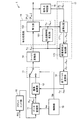
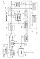
図1及び図2は、本発明に係る実施の形態1の受信装置1の主要構成を概略的に示す機能ブロック図である。図1は、第1の動作モード(通常動作モード)で動作するときの構成を示す図であり、図2は、第2の動作モード(妨害波低減動作モード)で動作するときの構成を示す図である。
1 and 2 are functional block diagrams schematically showing the main configuration of receiving
図1に示されるように、この受信装置1は、無線伝送路または有線伝送路から搬送波帯域の直交周波数分割多重化(OFDM)信号R(t)をOFDMシンボル単位で受信するフロントエンド部10を備えている。フロントエンド部10は、受信したOFDM信号R(t)を増幅し、その増幅信号を周波数変換してベースバンドOFDM信号を生成する。その後、フロントエンド部10は、ベースバンドOFDM信号に対してシンボルタイミング同期及び搬送波周波数同期などの同期処理を実行し、同期確立後、1有効シンボル期間のベースバンドOFDM信号をA/D変換して離散信号を生成する。離散信号は、各OFDMシンボルに含まれるN個(Nは2以上の整数)の変調サブキャリアの周波数(以下、サブキャリア周波数と呼ぶ。)f0,…,fN−1にそれぞれ対応するN個の時間ドメインの複素信号R0,R1,…,RN−1からなる。なお、n番目のサブキャリア周波数fnは、fn=n×f0、で与えられる。1有効シンボル期間は、1/f0である。
As shown in FIG. 1, the receiving
図1を参照すると、受信装置1は、離散信号を一時的に記憶するデータ蓄積部11と、複素減算部12と、データ蓄積部11の出力と複素減算部12の出力とのうちのいずれか一方を選択する信号選択部13と、信号選択部13の選択出力にN点の離散フーリエ変換(DFT)を施すフーリエ変換部14と、フーリエ変換部14のN個の複素出力X0,…,XN−1に等化処理を施す等化処理部15とを備えている。
Referring to FIG. 1, the receiving
データ蓄積部11及び信号選択部13の動作は制御部19によって制御される。具体的には、制御部19は、データ出力制御信号(繰り返しタイミング信号)Saをデータ蓄積部11に供給して、データ蓄積部11が離散信号を出力するタイミングを制御する。また、制御部19は、切替制御信号(切り替えタイミング信号)Sbを信号選択部13に供給して信号選択部13の選択先(データ蓄積部11の出力あるいは複素減算部12の出力)を制御することができる。
The operations of the
複素減算部12は、データ蓄積部11のN個の出力R0,…,RN−1から後述の逆フーリエ変換部18のN個の出力をそれぞれ減算してN個の減算信号(時間ドメイン信号)を生成し、これら減算信号を信号選択部13に出力する。信号選択部13は、選択制御信号Sbの値に応じてデータ蓄積部11の出力あるいは複素減算部12の出力のいずれか一方を選択し、選択したN個の出力をフーリエ変換部14に出力する。通常動作モードでは、信号選択部13は、図1に示されるようにデータ蓄積部11の出力を選択し、妨害波低減動作モードでは、信号選択部13は、図2に示されるように複素減算部12の出力を選択する。ここで、データ蓄積部11に入力されるデータ出力制御信号Saと、信号選択部13に入力される切替制御信号Sbとは互いに同期している。フーリエ変換部14による1回分のフーリエ変換処理に使用されるデータは、データ蓄積部11の出力あるいは複素減算部12の出力のいずれか一方のデータのみである。
The
フーリエ変換部14は、図1に示されるように、時間ドメインのN個の離散信号成分をフーリエ変換により周波数ドメイン信号であるN個の複素信号すなわち受信データシンボルX0,…,XN−1に変換(OFDM復調)する機能を有する。
等化処理部15は、伝送路特性推定部151と等化部152とを有する。伝送路特性推定部151は、N個の受信データシンボルX0,…,XN−1に含まれる既知の受信パイロットシンボルを用いてサブキャリア周波数f0,…,fN−1にそれぞれ対応するN個の伝送路特性h0,…,hN−1を推定する機能を有する。受信パイロットシンボルは、たとえば、時間方向及び周波数方向にそれぞれ分散して配置されている。これら受信パイロットシンボルの伝送路特性を推定した後に、受信パイロットシンボル以外の受信データシンボルの周波数特性を補間することが可能である。たとえば、日本のデジタル放送規格であるISDB−T(Integrated Services Digital Broadcasting for Terrestrial)やDVB−T(Digital Video Broadcasting − Terrestrial)では、OFDM信号の1シンボル期間内で周波数方向に12サブキャリアおき、シンボル方向(時間方向)には4サブキャリアおきにパイロットキャリアが挿入されているため、パイロットキャリアに対して推定された伝送路特性を時間方向及び周波数方向に内挿補間することで全てのサブキャリア周波数に対する伝送路特性を求めることができる。
The
等化部152は、たとえば、公知のZF(ゼロフォーシング)基準やMMSE(最小自乗誤差)基準による等化を行うことができる。ZF基準による等化を行う場合には、次式(1)に示されるように、サブキャリア周波数fkに対応する複素信号Xkを伝送路特性hkで複素除算することで等化信号[Xk]を算出することができる。
[Xk]=Xk/dk …(1)
The
[X k ] = X k / d k (1)
図1に示されるように、受信装置1はさらに信号点判定部16及び妨害波推定部17を備える。信号点判定部16は、等化部152から出力された周波数ドメインのN個の等化信号[X0],…,[XN−1]にそれぞれ対応する信号点を判定する機能を有する。信号点は、サブキャリア変調に使用されたディジタル変調方式に従って判定される。ディジタル変調方式としては、たとえば、QPSK(Quadrature Phase Shift Keying)、QAM(Quadrature Amplitude Modulation)、多値QAMあるいは多値PSKが挙げられる。各等化信号が当該ディジタル変調方式で規定される信号点(たとえば、16QAMの場合は16個の信号点)のいずれに対応するかが判定される。
As illustrated in FIG. 1, the
妨害波推定部17は、フーリエ変換部14の等化前の出力X0〜XN−1と等化処理部15の出力[X0]〜[XN−1]とに基づいて、サブキャリア周波数f0,…,fN−1にそれぞれ対応するN個の周波数ドメイン妨害波成分Z0,…,ZN−1を推定する機能を有する。
Based on the outputs X 0 to X N−1 before equalization of the
図1に示されるように、妨害波推定部17は、逆等化部171と妨害波成分抽出部172とを含む。逆等化部171は、信号点判定部16から出力された信号点のデータシンボルd0,…,dN−1と伝送路特性の推定値h0,…,hN−1とに基づいて、妨害波の影響が少ない受信データシンボルY0,…,YN−1を推定する。具体的には、ZF基準による逆等化の場合には、次式(2)に示されるように、サブキャリア周波数fkに対応するデータシンボルdkに推定値hkを複素乗算することで、サブキャリア周波数fkに対応する受信データシンボルYkを算出することができる。
Yk=dk×hk …(2)
As illustrated in FIG. 1, the interference
Y k = d k × h k (2)
妨害波成分抽出部172は、フーリエ変換部14の等化前の出力X0〜XN−1から受信データシンボルY0〜YN−1をそれぞれ複素減算することで周波数ドメイン妨害波信号を生成することができる。具体的には、次式(3)により、サブキャリア周波数fkに対応する周波数ドメイン妨害波信号Zkを算出することができる。
Zk=Xk−Yk …(3)
Interference wave
Z k = X k −Y k (3)
妨害波低減動作モードは、通常動作モードが実行された後に実行される。このとき、図2に示されるように、データ蓄積部11は、同一の有効シンボル期間内の時間ドメインの複素信号R0,R1,…,RN−1を再度出力する。逆フーリエ変換部18は、妨害波成分抽出部172のN個の出力Z0,…,ZN−1に対して逆離散フーリエ変換を実行することで時間ドメインのN個の複素妨害波信号z0,…,zN−1を生成する。複素減算部12は、データ蓄積部11の複素出力R0,…,RN−1から複素妨害波信号z0,…,zN−1をそれぞれ複素減算することで、妨害波の影響が低減したN個の時間ドメイン信号を生成することができる。
The interference wave reduction operation mode is executed after the normal operation mode is executed. At this time, as shown in FIG. 2, the
図2に示されるように、妨害波低減動作モードでは、信号選択部13の選択先は、複素減算部12の出力となる。このとき、フーリエ変換部14は、複素減算部12のN個の出力に対して離散フーリエ変換を実行して周波数ドメインのN個の複素データシンボルX0 (1),…,XN−1 (1)を生成する(ステップS1)。また、等化処理部15では、伝送路特性推定部151は、複素データシンボルX0 (1),…,XN−1 (1)に含まれる受信パイロットシンボルに基づいてN個の伝送路特性h0 (1),…,hN−1 (1)を推定する(ステップS2)。等化部152は、伝送路特性h0 (1),…,hN−1 (1)を用いてフーリエ変換部14の出力を等化することによりN個の等化信号[X0 (1)],…,[XN−1 (1)]を生成することとなる(ステップS3)。
As shown in FIG. 2, in the interference wave reduction operation mode, the selection destination of the
また、信号点判定部16は、等化信号[X0 (1)],…,[XN−1 (1)]にそれぞれ対応するN個の信号点の受信データシンボルd0 (1),…,dN−1 (1)を出力する(ステップS4)。その後、逆等化部171は、受信データシンボルY0 (1),…,YN−1 (1)を生成し(ステップS5)、次いで、妨害波成分抽出部172は、フーリエ変換部14の出力X0 (1)〜XN−1 (1)から受信データシンボルY0 (1)〜YN−1 (1)をそれぞれ複素減算することで周波数ドメイン妨害波信号Z0 (1)〜ZN−1 (1)を生成する(ステップS5)。さらに、逆フーリエ変換部18は、周波数ドメイン妨害波信号Z0 (1)〜ZN−1 (1)を逆離散フーリエ変換して時間ドメインのN個の複素妨害波信号z0 (1),…,zN−1 (1)を生成する(ステップS6)。そして、複素減算部12は、データ蓄積部11の複素出力R0,…,RN−1から複素妨害波信号z0 (1),…,zN−1 (1)をそれぞれ複素減算することで、妨害波の影響が低減した時間ドメイン信号を生成することができる(ステップS7)。
In addition, the signal
制御部19は、妨害波低減動作モードにおける以上のステップS1〜S7の処理を任意回数(0回も含む。)だけ繰り返し実行させることができる。
The
以上に説明したように実施の形態1によれば、伝送路特性が高速に時間変動する通信環境下でも、伝送路特性の変動に対する追従性が高い処理を実行することができるため、同一チャンネル妨害成分を効果的に抑圧することができる。また、たとえ妨害波が受信チャンネルの広い範囲に亘って存在する場合でも、妨害波推定部17は、同一チャンネル妨害成分Z0〜ZN−1を精度よく検出し、これら同一チャンネル妨害成分Z0〜ZN−1を効果的に抑圧することができる。したがって、高い受信性能を確保することができる。特に移動体がOFDM信号を受信する場合には、伝送路特性が高速に時間変動しやすいため、本実施の形態の受信装置1は有効である。
As described above, according to the first embodiment, even in a communication environment in which the transmission path characteristics fluctuate at high speed, it is possible to execute processing with high followability to fluctuations in the transmission path characteristics. The component can be effectively suppressed. Further, even when the jamming wave exists over a wide range of the reception channel, the jamming
また、逆フーリエ変換部18は、推定された妨害成分Z0〜ZN−1やZ0 (1)〜ZN−1 (1)を時間ドメイン信号z0,…,zN−1やz0 (1),…,zN−1 (1)に変換し、複素減算部12は、これら時間ドメイン信号を受信信号R0〜RN−1から除去している。その後、フーリエ変換及び等化処理が実行される。このため、特に妨害成分の電力が大きい場合には、複素減算部12によりフーリエ変換部14への入力信号の振幅が適切なレベルに変換されたうえで、離散フーリエ変換が実行されることとなる。したがって、フーリエ変換部14よりも後段の回路のダイナミックレンジを有効に活用することが可能である。また、同一チャンネル妨害抑圧後の受信性能を大幅に向上することができる。
The inverse
実施の形態2.
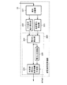
次に、本発明に係る実施の形態2について説明する。図3は、実施の形態2の受信装置2の主要構成を概略的に示す機能ブロック図である。図3に示されるように、本実施の形態の受信装置2は、上記実施の形態1の構成に加えて誤差評価部20を有している。受信装置2の構成は、制御部19B及び誤差評価部20を除いて実施の形態1の受信装置1の構成と同じである。
Next, a second embodiment according to the present invention will be described. FIG. 3 is a functional block diagram schematically showing a main configuration of receiving
誤差評価部20は、周波数ドメインの等化信号[X0],…,[XN−1]と信号点のデータシンボルd0,…,dN−1との間の誤差成分(等化出力[X0]〜[XN−1]に残留する雑音成分)を検出する機能を有する。制御部19Bは、実施の形態1の制御部19と同じ機能を有し、この機能に加えて、誤差評価部20による検出結果に応じてデータ蓄積部11及び信号選択部13の動作を制御する機能を有する。信号点判定部16の出力は、同一チャンネル妨害の影響が無視できない程大きい場合には、信号点を正確に再現するとは限らないため、判定誤差が生じている可能性がある。この場合には、その判定誤差の大きさや程度によっては、同一チャンネル妨害抑圧処理を行うことによってかえって受信性能が劣化する場合がある。そこで、本実施の形態では、制御部19Bは、誤差評価部20で検出された誤差成分に応じて、たとえば、上記の妨害波低減動作モード(同一チャンネル妨害抑圧処理を実行する動作モード)を実行するか否か、あるいは妨害波低減動作モードを継続するか否かを判断することができる。
図3に示されるように、誤差評価部20は、誤差比較部201と誤差判定部202とを含む。誤差比較部201は、等化部152の複素信号出力と信号点判定部16の複素信号出力とを入力とし、これら複素信号出力の差分の振幅または振幅の2乗値を全サブキャリア周波数分算出し、その平均値(以下、「誤差平均値」ともいう)を算出する機能を有する。なお、振幅の2乗値は、当該差分Δと当該差分の複素共役Δ*との積として算出され、振幅の値は、当該積の2乗根として算出される。より具体的には、通常動作モードでは、図3に示されるように、等化部152の複素信号出力[X0]〜[XN−1]と信号点判定部16の複素信号出力d0〜dN−1とを入力とするとき、誤差比較部201は、次式(4A),(4B)のいずれか一方に従って、誤差平均値<Δ>を算出することができる。

また、誤差評価部20は、通常動作モードの場合(同一チャンネル妨害成分を抑圧しない場合)と妨害波低減動作モードの場合(同一チャンネル妨害成分を抑圧した場合)とで誤差平均値を比較することができる。その比較結果は、たとえば、同一チャンネル妨害成分を抑圧していない場合の誤差平均値<Δ>0から抑圧した場合の誤差平均値<Δ>1を引き算した結果として出力されることができる。あるいは、誤差比較部201は、誤差平均値<Δ>0,<Δ>1の大小関係を表す信号とその差分(=<Δ>0−<Δ>1)の絶対値を表す信号とを出力してもよく、同一チャンネル妨害成分の抑圧効果を判定できる情報であれば出力信号の形式は、制限されるものではない。
Further, the
次に、誤差判定部202は、誤差比較部201の出力を入力とし、同一チャンネル妨害成分の抑圧効果を表す信号と外部から入力される誤差判定基準値Erefとに基づいて、同一チャンネル妨害成分の抑圧効果の有無を判定することができる。たとえば、誤差比較部201の出力が誤差平均値の引き算結果である場合には、その引き算結果を誤差判定基準値Erefと比較し、誤差平均値の引き算結果が誤差判定基準値Erefよりも大きい場合には同一チャンネル妨害の抑圧効果があったと判定し、その判定結果を制御部19Bに出力することができる。
Next, the
以上に説明したように実施の形態2によれば、誤差評価部20で検出された誤差成分に応じて、データ蓄積部11及び信号選択部13の動作を制御することができる。たとえば、制御部19Bは、通常動作モード実行時と妨害波低減モード実行時との間の誤差成分の大きさや変化に応じて妨害波低減モード(妨害抑圧処理)を実行するか否か判断することができるため、同一チャンネル妨害抑圧処理が不要な場合や、同一チャンネル妨害成分の検出誤差の影響などで受信性能がかえって劣化することが予想される場合には、妨害波低減モードの実行を回避することができる。したがって、伝送路特性の変動や妨害成分の変化、あるいは受信信号の状態に応じて適応的かつ適切に妨害成分を抑圧することができる。
As described above, according to the second embodiment, the operations of the
実施の形態3.
次に、本発明に係る実施の形態3について説明する。図4は、実施の形態3の受信装置3の主要構成を概略的に示す機能ブロック図である。図4に示されるように、本実施の形態の受信装置3は、遅延プロファイル推定部21及び妨害波抑圧評価部22を有している。受信装置3の構成は、制御部19Cと遅延プロファイル推定部21と妨害波抑圧評価部22とを除いて、実施の形態1の受信装置1の構成と同じである。
Next, a third embodiment according to the present invention will be described. FIG. 4 is a functional block diagram schematically showing the main configuration of receiving
遅延プロファイル推定部21は、フーリエ変換部14の出力X0〜XN−1に基づいて伝送路特性の遅延プロファイル(OFDM信号の希望波と遅延波と雑音成分との電力分布)を推定する機能を有する。また、妨害波抑圧評価部22は、遅延プロファイルの電力分布に基づいて妨害波が抑圧された否かを判定し、その判定結果を制御部19Cに通知することができる。制御部19Cは、上記実施の形態1の制御部19の機能に加えて、妨害波抑圧評価部22による判定結果に基づいてデータ蓄積部11及び信号選択部13の動作を制御する機能を有する。
The delay
図5は、遅延プロファイル推定部21の構成例を示す機能ブロック図である。図5に示されるように、遅延プロファイル推定部21は、副伝送路特性推定部210と、逆フーリエ変換部214とパス電力算出部215とを有している。副伝送路特性推定部210はさらにパイロット伝送路特性推定部211とパイロット信号生成部212と伝送路特性内挿部213とを含む。
FIG. 5 is a functional block diagram illustrating a configuration example of the delay
パイロット伝送路特性推定部211は、フーリエ変換部14の複素信号出力X0〜XN−1及びパイロット信号生成部212の複素信号出力とを入力とし、パイロット信号生成部212から供給された基準パイロット信号を用いて、入力された複素信号X0〜XN−1中の受信パイロット信号から伝送路特性を推定する。具体的には、パイロット伝送路特性推定部211は、受信パイロット信号を既知の基準パイロット信号で複素除算することで受信パイロット信号に対する伝送路特性を複素信号として生成することができる。逆フーリエ変換部214は、伝送路特性内挿部213の出力を内挿補間することにより、各サブキャリア周波数に対する伝送路特性を算出して出力することができる。たとえば、伝送路特性内挿部213は、時間方向に内挿補間した結果を出力してもよいし、周波数方向に内挿補間した結果を出力してもよいし、あるいは、時間及び周波数方向に内挿補間した結果を出力しても良い。なお、伝送路特性推定部151で得られた内挿補間のデータを流用することもできる。
The pilot transmission line
逆フーリエ変換部214は、伝送路特性内挿部213の複素信号出力を入力とし、これら複素信号出力を逆離散フーリエ変換することで時間ドメインの複素信号を生成することができる。ここで、逆フーリエ変換部214で使用される入力データの点数Mは、サブキャリア周波数の全数N(>M)よりも少なくてもよい。よって、逆フーリエ変換部214は、時間ドメインにおけるM個の複素信号P0,…,PM−1を出力することとなる。
The inverse
パス電力算出部215は、複素信号P0,…,PM−1の振幅または振幅の2乗値を電力値として成分毎に計算することにより遅延プロファイルを生成する。図6(A),(B)は、遅延プロファイルを例示するグラフである。図6(A)では、送信機から送られてきた主波(希望波)に対し、反射などによって遅延した遅延波が存在し、さらに同一チャンネル妨害成分と熱雑音とが重畳された場合の遅延プロファイルの推定結果が示されている。すなわち、図6(A)の電力分布は、主波の電力分布30mと、遅延波の電力分布30dと、電力値Pn付近の雑音電力成分とを含む。主波の電力分布30mと遅延波の電力分布30dは、所望の電力成分(以下、「パス成分」と呼ぶ。)の電力分布30Pであり、それ以外の成分は、熱雑音及び同一チャンネル妨害成分(以下「雑音成分」とも呼ぶ。)の電力分布を意味している。パス電力算出部215は、パス成分、熱雑音成分及び同一チャンネル妨害成分全ての電力を遅延時間毎に算出する。同一チャンネル妨害が抑圧された信号から遅延プロファイルを再度推定すると、図6(B)に示すものとなり、パス成分以外の電力成分が抑圧前に比べて小さくなる。したがって、同一チャンネル妨害抑圧処理前後の遅延プロファイル推定結果をもとに、抑圧効果を高精度に推定することができる。
Path
次に、図7は、妨害波抑圧評価部22の構成例を示す機能ブロック図である。図7に示されるように、妨害波抑圧評価部22は、判定処理部220、成分分離部221、パス成分電力算出部222及び雑音電力算出部223を有している。判定処理部220はさらに、電力比算出部224、電力比記憶部225及び判定部226を有している。
Next, FIG. 7 is a functional block diagram illustrating a configuration example of the interference wave
成分分離部221は、遅延プロファイルを示す信号から主波及び遅延波の電力分布と雑音電力分布とを分離し、主波及び遅延波の電力分布を示す信号をパス成分電力算出部222に供給し、雑音電力分布を示す信号を雑音電力算出部223に供給する。パス成分電力算出部222は、当該電力分布の電力値の全てを加算(積分)して第1の電力積分値を算出し、一方、雑音電力算出部223は、雑音電力分布の電力値の全てを加算(積分)して第2の電力積分値を算出する。
The
判定処理部220は、希望波及び遅延波の電力分布と雑音電力分布とを比較し、その比較結果に基づいて妨害波が抑圧された否かを判定することができる。具体的には、電力比算出部224は、第1の電力積分値と第2の電力積分値との比率(以下、電力比と呼ぶ。)を算出し、この電力比を電力比記憶部225に記憶させる。また、電力比算出部224は、算出された電力比を判定部226に与える。
The
判定部226は、電力比算出部224から供給された電力比に基づいて、妨害波が抑圧されたか否かを判定することができる。また、判定部226は、電力比記憶部225に記憶されている以前の電力比と、電力比算出部224から供給された現在の電力比とを比較して、電力比の変化を検出することが可能である。たとえば、判定部226は、電力比の現在値の方が電力比記憶部225に記憶されている以前の電力比よりも大きい場合に電力比が改善したと判定し、その改善量が再演算判定基準値RPrefよりも大きい場合には同一チャンネル妨害抑圧処理の効果があったと判定することができる。判定部226による判定結果は、制御部19Cに供給される。
The
以上に説明したように実施の形態3では、制御部19Cは、遅延プロファイル推定結果の変化をもとに同一チャンネル妨害の抑圧効果を推定したうえで妨害抑圧処理を実行するか否か判断することができるため、同一チャンネル妨害抑圧処理が不要な場合や、同一チャンネル妨害成分の検出誤差の影響などで受信性能がかえって劣化するおそれがある場合には、同一チャンネル妨害抑圧処理の実行を回避することができる。また、伝送路変動や妨害成分の変化、受信信号の状態に応じて適応的かつ適切に妨害成分を抑圧することができる。
As described above, in the third embodiment, the
実施の形態4.
図8は、本発明に係る実施の形態4の受信装置を構成する妨害波抑圧評価部22Mの構成を示す機能ブロック図である。本実施の形態の受信装置の構成は、妨害波抑圧評価部22Mを除いて、実施の形態3の受信装置3の構成と同じである。
Embodiment 4 FIG.
FIG. 8 is a functional block diagram showing a configuration of the jamming wave
図8に示されるように、この妨害波抑圧評価部22Mは、判定処理部230、成分分離部231及び雑音電力算出部232を有する。判定処理部230はさらに、雑音電力記憶部233及び判定部234を有している。
As illustrated in FIG. 8, the interference wave
成分分離部231は、遅延プロファイルを示す信号から雑音電力分布を分離し、雑音電力分布を示す信号を雑音電力算出部232に供給する。判定処理部230は、雑音電力分布に基づいて妨害波が抑圧された否かを判定することができる。具体的には、雑音電力算出部232は、雑音電力分布の電力値の全てを加算(積分)して電力積分値を算出し、これを雑音電力記憶部233に記憶させる。また、雑音電力比算出部232は、算出された雑音電力比を判定部234に与える。判定部234は、雑音電力算出部234から供給された電力比に基づいて、妨害波が抑圧されたか否かを判定することができる。また、判定部234は、雑音電力記憶部233に記憶されている以前の電力比と、雑音電力算出部232から供給された現在の電力比とを比較して、電力比の変化を検出することが可能である。たとえば、判定部234は、雑音電力比の現在値の方が雑音電力記憶部233に記憶されている以前の電力比よりも大きい場合に電力比が改善したと判定し、その改善量が再演算判定基準値RPrefよりも大きい場合には同一チャンネル妨害抑圧処理の効果があったと判定することができる。判定部234による判定結果は、制御部19Cに供給される。
The
以上に説明したように実施の形態4によれば、実施の形態3と同様に、遅延プロファイル推定結果の変化をもとに同一チャンネル妨害の抑圧効果を推定した上で妨害抑圧処理を実行するか否か判断することができるため、同一チャンネル妨害抑圧処理が不要な場合や、同一チャンネル妨害成分の検出誤差の影響等で受信性能がかえって劣化するおそれがある場合には、同一チャンネル妨害抑圧処理を回避することが可能となり、伝送路変動や妨害成分の変化、受信信号の状態に応じて適応的かつ適切に妨害成分を抑圧することができる。 As described above, according to the fourth embodiment, whether the interference suppression processing is executed after estimating the suppression effect of the co-channel interference based on the change in the delay profile estimation result, as in the third embodiment. Therefore, if the co-channel interference suppression processing is unnecessary or if there is a possibility that the reception performance may deteriorate due to the detection error of the co-channel interference component, the co-channel interference suppression processing is performed. Thus, the interference component can be adaptively and appropriately suppressed according to the transmission path fluctuation, the change of the interference component, and the state of the received signal.
実施の形態1〜4の変形例.
以上、図面を参照して本発明の実施形態について述べたが、これらは本発明の例示であり、上記以外の様々な構成を採用することもできる。たとえば、実施の形態2の構成と実施の形態3の構成とを組み合わせた実施の形態もあり得る。
Modified example of the first to fourth embodiments.
As mentioned above, although embodiment of this invention was described with reference to drawings, these are the illustrations of this invention, Various structures other than the above are also employable. For example, there may be an embodiment in which the configuration of the second embodiment and the configuration of the third embodiment are combined.
また、上記受信装置1〜3の機能の全部がハードウェア構成で実現されている必要はなく、受信装置1〜3の機能の一部が、マイクロプロセッサにより実行されるコンピュータプログラムで実現されてもよい。この場合、たとえば、マイクロプロセッサは、ハードディスク(磁気ディスク)、光ディスクまたはフラッシュメモリなどの記録媒体からコンピュータプログラムをロードし実行することによって当該機能の一部を実現することができる。
Further, it is not necessary that all the functions of the receiving
1〜3 受信装置、 10 フロントエンド部、 11 データ蓄積部、 12 複素減算部、 13 信号選択部、 14 フーリエ変換部、 15 等化処理部、 151 伝送路特性推定部、 152 等化部、 16 信号点判定部、 17 妨害波推定部、 171 逆等化部、 172 妨害波成分抽出部、 18 逆フーリエ変換部、 19,19B,19C 制御部、 20 誤差評価部、 201 誤差比較部、 202 誤差判定部、 21 遅延プロファイル推定部、 210 副伝送路特性推定部、 211 パイロット伝送路特性推定部、 212 パイロット信号生成部、 213 伝送路特性内挿部、 214 逆フーリエ変換部、 215 パス電力算出部、 22,22M 妨害波抑圧評価部、 220 判定処理部、 221 成分分離部、 222 パス成分電力算出部、 223 雑音電力算出部、 224 電力比算出部、 225 電力比記憶部、 226 判定部、 231 成分分離部、 232 雑音電力算出部、 233 雑音電力記憶部、 234 判定部。
1 to 3 receivers, 10 front end units, 11 data storage units, 12 complex subtraction units, 13 signal selection units, 14 Fourier transform units, 15 equalization processing units, 151 transmission path characteristic estimation units, 152 equalization units, 16 Signal point determination unit, 17 jamming wave estimation unit, 171 inverse equalization unit, 172 jamming wave component extraction unit, 18 inverse Fourier transform unit, 19, 19B, 19C control unit, 20 error evaluation unit, 201 error comparison unit, 202 error Determination unit, 21 delay profile estimation unit, 210 sub-transmission channel characteristic estimation unit, 211 pilot transmission channel characteristic estimation unit, 212 pilot signal generation unit, 213 transmission channel characteristic interpolation unit, 214 inverse Fourier transform unit, 215 path
Claims (11)
前記周波数分割多重化信号から離散信号を生成するフロントエンド部と、
前記離散信号を一時的に記憶した後に出力するデータ蓄積部と、
前記データ蓄積部により出力された当該離散信号から妨害波信号を減算して減算信号を生成する減算部と、
前記離散信号と前記減算信号とのうちのいずれか一方を選択して出力する信号選択部と、
前記信号選択部の出力に対して離散フーリエ変換を実行することにより複数の周波数ドメイン信号を生成するフーリエ変換部と、
前記複数の周波数ドメイン信号のうち前記パイロットキャリアに対応する受信パイロット信号に基づいて伝送路特性を推定し、当該推定された伝送路特性を用いて前記複数の周波数ドメイン信号に等化処理を施すことにより複数の周波数ドメイン等化信号を生成する等化処理部と、
前記複数の周波数ドメイン信号と前記複数の周波数ドメイン等化信号とに基づいて、前記複数の変調サブキャリアの周波数にそれぞれ対応する複数の周波数ドメイン妨害波成分を推定する妨害波推定部と、
前記複数の周波数ドメイン妨害波成分に対して逆離散フーリエ変換を実行して前記妨害波信号を生成する逆フーリエ変換部と、
前記データ蓄積部及び前記信号選択部の動作を個別に制御する制御部と、
前記変調サブキャリアに適用されたディジタル変調方式に従って、前記複数の周波数ドメイン等化信号にそれぞれ対応する複数の信号点を判定する信号点判定部と、
前記複数の周波数ドメイン等化信号と前記複数の信号点との間の誤差を検出する誤差評価部と、を備え、
前記制御部は、前記誤差評価部による検出結果に基づいて前記データ蓄積部及び前記信号選択部の動作を制御すること
を特徴とする受信装置。 A receiving apparatus for receiving a frequency division multiplexed signal in which a plurality of modulation subcarriers including a known pilot carrier are multiplexed,
A front end for generating a discrete signal from the frequency division multiplexed signal;
A data storage unit for outputting the discrete signals after temporarily storing them;
A subtracting unit that generates a subtracted signal by subtracting an interference signal from the discrete signal output by the data storage unit;
A signal selection unit that selects and outputs any one of the discrete signal and the subtraction signal;
A Fourier transform unit that generates a plurality of frequency domain signals by performing a discrete Fourier transform on the output of the signal selection unit;
A channel characteristic is estimated based on a received pilot signal corresponding to the pilot carrier among the plurality of frequency domain signals, and equalization processing is performed on the plurality of frequency domain signals using the estimated channel characteristic An equalization processing unit for generating a plurality of frequency domain equalized signals by
Based on the plurality of frequency domain signals and the plurality of frequency domain equalization signals, an interference wave estimation unit that estimates a plurality of frequency domain interference wave components respectively corresponding to the frequencies of the plurality of modulation subcarriers;
An inverse Fourier transform unit that performs an inverse discrete Fourier transform on the plurality of frequency domain interference wave components to generate the interference wave signal;
A control unit for individually controlling the operations of the data storage unit and the signal selection unit ;
A signal point determination unit for determining a plurality of signal points respectively corresponding to the plurality of frequency domain equalized signals according to the digital modulation scheme applied to the modulation subcarrier;
An error evaluator that detects errors between the plurality of frequency domain equalized signals and the plurality of signal points; and
The control unit controls operations of the data storage unit and the signal selection unit based on a detection result by the error evaluation unit.
Receiving apparatus according to claim.
前記データ蓄積部及び前記信号選択部は、第1の動作モードと第2の動作モードとを有し、
前記第1の動作モードでは、前記データ蓄積部から前記離散信号が出力されるとともに、前記信号選択部により前記離散信号が選択され、
前記第2の動作モードでは、前記データ蓄積部から前記離散信号が再度出力されるとともに、前記信号選択部により前記減算信号が選択される
ことを特徴とする受信装置。 The receiving device according to claim 1,
The data storage unit and the signal selection unit have a first operation mode and a second operation mode,
In the first operation mode, the discrete signal is output from the data storage unit, and the discrete signal is selected by the signal selection unit,
In the second operation mode, the discrete signal is output again from the data storage unit, and the subtraction signal is selected by the signal selection unit.
前記誤差評価部は、前記データ蓄積部及び前記信号選択部が前記第1の動作モードで動作したときの当該誤差と、前記データ蓄積部及び前記信号選択部が前記第2の動作モードで動作したときの当該誤差とを比較し、
前記制御部は、前記誤差評価部による比較結果に基づいて前記データ蓄積部及び前記信号選択部の動作を制御する
ことを特徴とする受信装置。 The receiving device according to claim 2 or 3 ,
The error evaluation unit includes the error when the data storage unit and the signal selection unit operate in the first operation mode, and the data storage unit and the signal selection unit operate in the second operation mode. Compare with the error when
The control unit controls the operations of the data storage unit and the signal selection unit based on a comparison result by the error evaluation unit.
前記複数の周波数ドメイン信号に基づいて前記伝送路特性の遅延プロファイルを推定する遅延プロファイル推定部と、
前記遅延プロファイルの電力分布に基づいて妨害波が抑圧されたか否かを判定する妨害波抑圧評価部と
をさらに備え、
前記制御部は、前記妨害波抑圧評価部による判定結果に基づいて前記データ蓄積部及び前記信号選択部の動作を制御する
ことを特徴とする受信装置。 The receiving device according to claim 2 or 3,
A delay profile estimator that estimates a delay profile of the transmission path characteristics based on the plurality of frequency domain signals;
An interference wave suppression evaluation unit that determines whether an interference wave is suppressed based on the power distribution of the delay profile;
The control unit controls the operations of the data storage unit and the signal selection unit based on a determination result by the interference wave suppression evaluation unit.
前記妨害波抑圧評価部は、
前記遅延プロファイルから希望波及び遅延波の電力分布と当該希望波及び遅延波以外の雑音電力分布とを分離する成分分離部と、
前記希望波及び遅延波の電力分布と前記雑音電力分布とを比較し、その比較結果に基づいて前記妨害波が抑圧されたか否かを判定する判定処理部と
を含むことを特徴とする受信装置。 The receiving device according to claim 5 ,
The interference wave suppression evaluation unit
A component separation unit that separates the power distribution of the desired wave and the delayed wave and the noise power distribution other than the desired wave and the delayed wave from the delay profile;
A receiving apparatus comprising: a determination processing unit that compares the power distribution of the desired wave and the delayed wave with the noise power distribution and determines whether or not the interference wave is suppressed based on the comparison result; .
前記判定処理部は、
前記希望波及び遅延波の電力分布に基づいて第1の電力積分値を算出するとともに前記雑音電力分布に基づいて第2の電力積分値を算出する電力算出部と、
前記第1の電力積分値と前記第2の電力積分値との比率を算出し、前記比率の変化に基づいて前記妨害波が抑圧されたか否かを判定する判定部と
を含むことを特徴とする受信装置。 The receiving device according to claim 6 ,
The determination processing unit
A power calculator that calculates a first power integral value based on the power distribution of the desired wave and the delayed wave and calculates a second power integral value based on the noise power distribution;
And a determination unit that calculates a ratio between the first power integration value and the second power integration value and determines whether or not the interference wave is suppressed based on a change in the ratio. Receiving device.
前記妨害波抑圧評価部は、
前記遅延プロファイルから希望波及び遅延波以外の雑音電力分布を分離する成分分離部と、
前記雑音電力分布に基づいて前記妨害波が抑圧されたか否かを判定する判定処理部と
を含むことを特徴とする受信装置。 The receiving device according to claim 5 ,
The interference wave suppression evaluation unit
A component separation unit that separates a noise power distribution other than the desired wave and the delayed wave from the delay profile;
And a determination processing unit that determines whether or not the interference wave is suppressed based on the noise power distribution.
前記判定処理部は、
前記雑音電力分布に基づいて電力積分値を算出する電力算出部と、
前記電力積分値の変化に基づいて前記妨害波が抑圧されたか否かを判定する判定部と
を含むことを特徴とする受信装置。 The receiving device according to claim 8 , wherein
The determination processing unit
A power calculator that calculates a power integral value based on the noise power distribution;
And a determination unit that determines whether or not the interference wave is suppressed based on a change in the power integration value.
前記遅延プロファイル推定部は、
前記複数の周波数ドメイン信号のうち前記パイロットキャリアに対応する受信パイロット信号に基づいて伝送路特性を推定する副伝送路特性推定部と、
前記副伝送路特性推定部により推定された伝送路特性に対して逆離散フーリエ変換を実行することにより時間ドメインの複素信号を生成する逆フーリエ変換部と、
前記複素信号の電力分布を前記遅延プロファイルとして算出する電力算出部と
を含むことを特徴とする受信装置。 The receiving device according to any one of claims 5 to 9 ,
The delay profile estimation unit includes:
A sub-channel characteristic estimation unit that estimates a channel characteristic based on a received pilot signal corresponding to the pilot carrier among the plurality of frequency domain signals;
An inverse Fourier transform unit that generates a time-domain complex signal by performing an inverse discrete Fourier transform on the channel characteristics estimated by the sub-channel characteristic estimation unit;
And a power calculator that calculates a power distribution of the complex signal as the delay profile.
前記変調サブキャリアに適用されたディジタル変調方式に従って、前記複数の周波数ドメイン等化信号にそれぞれ対応する複数の信号点を判定する信号点判定部をさらに備え、
前記妨害波推定部は、
前記複数の信号点と前記等化処理部により推定された当該伝送路特性とに基づいて、前記複数の信号点にそれぞれ対応する複数の受信データシンボルを推定する逆等化部と、
前記複数の周波数ドメイン信号から、当該推定された複数の受信データシンボルをそれぞれ減算することで前記複数の周波数ドメイン妨害波成分としての複数の周波数ドメイン妨害波信号を生成する妨害波成分抽出部と
を含むことを特徴とする受信装置。 The receiving device according to any one of claims 1 to 3,
Further comprising a signal point determination unit for determining a plurality of signal points respectively corresponding to the plurality of frequency domain equalized signals according to the digital modulation scheme applied to the modulation subcarrier,
The interference wave estimation unit includes:
An inverse equalization unit configured to estimate a plurality of received data symbols respectively corresponding to the plurality of signal points based on the plurality of signal points and the transmission path characteristics estimated by the equalization processing unit;
An interference wave component extraction unit that generates a plurality of frequency domain interference wave signals as the plurality of frequency domain interference wave components by subtracting the estimated plurality of received data symbols from the plurality of frequency domain signals, respectively. A receiving apparatus comprising:
Priority Applications (1)
| Application Number | Priority Date | Filing Date | Title |
|---|---|---|---|
| JP2011261833A JP5812827B2 (en) | 2011-11-30 | 2011-11-30 | Receiver |
Applications Claiming Priority (1)
| Application Number | Priority Date | Filing Date | Title |
|---|---|---|---|
| JP2011261833A JP5812827B2 (en) | 2011-11-30 | 2011-11-30 | Receiver |
Publications (3)
| Publication Number | Publication Date |
|---|---|
| JP2013115708A JP2013115708A (en) | 2013-06-10 |
| JP2013115708A5 JP2013115708A5 (en) | 2014-11-06 |
| JP5812827B2 true JP5812827B2 (en) | 2015-11-17 |
Family
ID=48710850
Family Applications (1)
| Application Number | Title | Priority Date | Filing Date |
|---|---|---|---|
| JP2011261833A Active JP5812827B2 (en) | 2011-11-30 | 2011-11-30 | Receiver |
Country Status (1)
| Country | Link |
|---|---|
| JP (1) | JP5812827B2 (en) |
Families Citing this family (1)
| Publication number | Priority date | Publication date | Assignee | Title |
|---|---|---|---|---|
| JP7122878B2 (en) | 2018-06-13 | 2022-08-22 | 日本信号株式会社 | wireless communication system |
Family Cites Families (5)
| Publication number | Priority date | Publication date | Assignee | Title |
|---|---|---|---|---|
| JP4298320B2 (en) * | 2002-11-08 | 2009-07-15 | 富士通株式会社 | Receiver for OFDM transmission system |
| US7340000B1 (en) * | 2004-08-13 | 2008-03-04 | Cisco Technology, Inc. | Decision feedback equalizer in an OFDM WLAN receiver |
| JP2010062805A (en) * | 2008-09-03 | 2010-03-18 | Nara Institute Of Science & Technology | Radio communication device and semiconductor integrated circuit device |
| JP5428788B2 (en) * | 2009-11-13 | 2014-02-26 | シャープ株式会社 | Receiving device, receiving method, and receiving program |
| JP2011217191A (en) * | 2010-03-31 | 2011-10-27 | Fujitsu Ltd | Method of receiving ofdm signal and receiving apparatus implementing the method |
-
2011
- 2011-11-30 JP JP2011261833A patent/JP5812827B2/en active Active
Also Published As
| Publication number | Publication date |
|---|---|
| JP2013115708A (en) | 2013-06-10 |
Similar Documents
| Publication | Publication Date | Title |
|---|---|---|
| KR100610706B1 (en) | Ofdm system receiver apparatus | |
| US8363539B2 (en) | OFDM receiver and OFDM receiving method | |
| JP4600559B2 (en) | Receiving device, receiving method, and program | |
| JP2005287043A (en) | Receiver | |
| JP3740468B2 (en) | OFDM receiver and data demodulation method | |
| WO2007055042A1 (en) | Device and method for receiving orthogonal frequency division multiplexing signal | |
| JP4545209B2 (en) | Orthogonal frequency division multiplexed signal receiving apparatus and receiving method thereof | |
| JP5896795B2 (en) | Equalizer, receiver, and equalization method | |
| US8428538B2 (en) | Channel estimator | |
| JPWO2008099572A1 (en) | Receiving apparatus and receiving method | |
| US7986615B2 (en) | Demodulating circuit, demodulating method, program, and receiving device | |
| JP4780161B2 (en) | Receiving device, receiving method, and program | |
| JP5023007B2 (en) | OFDM signal receiving apparatus and relay apparatus | |
| JP5951102B2 (en) | Communication line quality estimation apparatus and receiver | |
| JP5812827B2 (en) | Receiver | |
| US20090135931A1 (en) | Reception apparatus, reception method and program | |
| JP2012175283A (en) | Ofdm signal receiving apparatus and relay apparatus | |
| JP5023006B2 (en) | OFDM signal receiving apparatus and relay apparatus | |
| JP4486008B2 (en) | Receiver | |
| JP5460487B2 (en) | OFDM signal receiving apparatus and relay apparatus | |
| JP5099148B2 (en) | Receiving device, receiving method, and program | |
| JP2010268044A (en) | Receiving device | |
| JP2013201578A (en) | Transmission line response estimator, and broadcast receiver | |
| JP5518261B2 (en) | Equalizer and equalization method | |
| JP5306111B2 (en) | OFDM receiver |
Legal Events
| Date | Code | Title | Description |
|---|---|---|---|
| A521 | Request for written amendment filed |
Free format text: JAPANESE INTERMEDIATE CODE: A523 Effective date: 20140917 |
|
| A621 | Written request for application examination |
Free format text: JAPANESE INTERMEDIATE CODE: A621 Effective date: 20140917 |
|
| A977 | Report on retrieval |
Free format text: JAPANESE INTERMEDIATE CODE: A971007 Effective date: 20150427 |
|
| A131 | Notification of reasons for refusal |
Free format text: JAPANESE INTERMEDIATE CODE: A131 Effective date: 20150616 |
|
| A521 | Request for written amendment filed |
Free format text: JAPANESE INTERMEDIATE CODE: A523 Effective date: 20150730 |
|
| TRDD | Decision of grant or rejection written | ||
| A01 | Written decision to grant a patent or to grant a registration (utility model) |
Free format text: JAPANESE INTERMEDIATE CODE: A01 Effective date: 20150818 |
|
| A61 | First payment of annual fees (during grant procedure) |
Free format text: JAPANESE INTERMEDIATE CODE: A61 Effective date: 20150915 |
|
| R150 | Certificate of patent or registration of utility model |
Ref document number: 5812827 Country of ref document: JP Free format text: JAPANESE INTERMEDIATE CODE: R150 |
|
| R250 | Receipt of annual fees |
Free format text: JAPANESE INTERMEDIATE CODE: R250 |
|
| R250 | Receipt of annual fees |
Free format text: JAPANESE INTERMEDIATE CODE: R250 |
|
| R250 | Receipt of annual fees |
Free format text: JAPANESE INTERMEDIATE CODE: R250 |
|
| R250 | Receipt of annual fees |
Free format text: JAPANESE INTERMEDIATE CODE: R250 |
|
| R250 | Receipt of annual fees |
Free format text: JAPANESE INTERMEDIATE CODE: R250 |
|
| R250 | Receipt of annual fees |
Free format text: JAPANESE INTERMEDIATE CODE: R250 |