JP5896795B2 - Equalizer, receiver, and equalization method - Google Patents
Equalizer, receiver, and equalization method Download PDFInfo
- Publication number
- JP5896795B2 JP5896795B2 JP2012057811A JP2012057811A JP5896795B2 JP 5896795 B2 JP5896795 B2 JP 5896795B2 JP 2012057811 A JP2012057811 A JP 2012057811A JP 2012057811 A JP2012057811 A JP 2012057811A JP 5896795 B2 JP5896795 B2 JP 5896795B2
- Authority
- JP
- Japan
- Prior art keywords
- unit
- correlation
- value
- threshold
- filter
- Prior art date
- Legal status (The legal status is an assumption and is not a legal conclusion. Google has not performed a legal analysis and makes no representation as to the accuracy of the status listed.)
- Expired - Fee Related
Links
Images

Description
本発明は、受信信号が伝送路から受けた歪みを補償する等化技術に関し、特に、受信信号が伝送路から受けた歪みを既知信号系列を用いて補償する等化技術に関する。 The present invention relates to an equalization technique for compensating for distortion received by a received signal from a transmission path, and more particularly, to an equalization technique for compensating for distortion received by a received signal from a transmission path using a known signal sequence.
無線通信システムや地上デジタル放送システムにおいて、受信機は、送信機から直接到来する到来波(直接波)を受信するだけでなく、送信機から送信された後に建物などの障害物で反射、回折あるいは散乱を受けた到来波(非直接波)をも受信することがある。遅延プロファイルは、このような複数の到来波の遅延時間、振幅及び位相に関する情報を示すものである。特開2011−199391号(特許文献1)には、遅延プロファイルの推定結果を用いて伝送路応答を推定する伝送路応答推定器が開示されている。 In wireless communication systems and digital terrestrial broadcasting systems, a receiver not only receives an incoming wave (direct wave) that directly arrives from a transmitter, but also reflects, diffracts, or is reflected by an obstacle such as a building after being transmitted from the transmitter. Incoming waves (indirect waves) that have been scattered may also be received. The delay profile indicates information regarding the delay time, amplitude, and phase of such a plurality of incoming waves. Japanese Patent Laying-Open No. 2011-199391 (Patent Document 1) discloses a transmission path response estimator that estimates a transmission path response using a delay profile estimation result.
特許文献1に開示されている伝送路応答推定器は、受信信号に含まれる疑似ランダム系列(PN系列:Pseudo−random Noise series)と自己発生させた既知の疑似ランダム系列との時間相関を算出して相関波形を生成する相関部と、この相関波形を時間(シンボル)方向に平滑化する平滑化部と、この平滑化部の出力のうちのピーク部分のみを選択して遅延プロファイルを推定する有効パス判定部とを有している。平滑化部は相関波形を時間(シンボル)方向に平滑化するので、遅延プロファイルの推定結果に含まれる雑音成分を抑圧することができる。
The transmission path response estimator disclosed in
しかしながら、特許文献1に開示されている技術では、受信機が送信機に対して移動する受信環境下では、遅延プロファイルの推定精度が低下するという問題がある。
However, the technique disclosed in
上記に鑑みて本発明の目的は、受信機が移動する環境下でも、遅延プロファイルの推定精度の低下を抑制することができる等化装置、受信装置及び等化方法を提供することである。 In view of the above, an object of the present invention is to provide an equalization apparatus, a reception apparatus, and an equalization method that can suppress a decrease in delay profile estimation accuracy even in an environment in which the receiver moves.
本発明の第1の態様による等価装置は、既知信号系列と情報信号を含む有効シンボルとを有する伝送シンボルが連続的に送信装置から送信されたときに、受信装置で受信された前記伝送シンボルの受信信号の歪みを補正する等化装置であって、既知信号系列を供給する既知信号系列生成部と、前記伝送シンボル毎に前記既知信号系列と前記受信信号との間の相互相関を計算して相互相関値の系列を得る相関演算部と、前記相互相関値の系列から、当該受信装置で受信された複数の到来波にそれぞれ対応する複数の相関ピーク値の位置を前記伝送シンボル毎に検出する到来波検出部と、前記相互相関値のそれぞれの位置に基づいて、前記相互相関値の系列に対して、前記複数の相関ピーク値のうちの少なくとも1つに対応する区間を含む、複数の区間を設定する区間設定部と、前記複数の相関ピーク値の時間変動を検出する変動量検出部と、前記相互相関値の系列に対してシンボル方向の平滑化フィルタリングを前記複数の区間の区間毎に実行して推定遅延プロファイルを生成するフィルタ部と、前記変動量検出部により検出された当該時間変動に応じて前記フィルタ部の平滑化フィルタリング特性を前記複数の区間の区間毎に変化させるフィルタ制御部と、前記推定遅延プロファイルに基づいて前記受信信号の歪みを補正する等化処理を実行する等化処理部とを備え、前記フィルタ制御部は、前記時間変動が大きい程、前記フィルタ部の通過帯域が広くなるように前記平滑化フィルタリング特性を変化させることを特徴とする。 The equivalent apparatus according to the first aspect of the present invention provides a transmission symbol received by a receiving apparatus when a transmission symbol having a known signal sequence and an effective symbol including an information signal is continuously transmitted from the transmitting apparatus. An equalization apparatus for correcting distortion of a received signal, wherein a known signal sequence generation unit that supplies a known signal sequence and calculates a cross-correlation between the known signal sequence and the received signal for each transmission symbol A correlation calculation unit that obtains a sequence of cross-correlation values, and detects positions of a plurality of correlation peak values respectively corresponding to a plurality of incoming waves received by the receiving apparatus from the cross-correlation value sequence for each transmission symbol. an arrival wave detection unit, based on the respective positions of the cross-correlation value with respect to sequence of the cross-correlation values, including a section corresponding to at least one of the plurality of correlation peak values, a plurality A section setting unit for setting a segment, the changing amount detecting unit for detecting a time variation of the plurality of correlation peak value, the cross-correlation value of a sequence symbol direction smoothing filtering each section of the plurality of sections with respect to And a filter control for changing the smoothing filtering characteristic of the filter unit for each of the sections according to the time variation detected by the variation amount detection unit. And an equalization processing unit that executes an equalization process for correcting distortion of the received signal based on the estimated delay profile, and the filter control unit passes through the filter unit as the time variation increases. The smoothing filtering characteristic is changed so as to widen the band.
本発明の第2の態様による受信装置は、既知信号系列と情報信号を含む有効シンボルとを有する伝送シンボルが連続的に送信装置から送信されたとき、前記伝送シンボルの信号を受信する信号受信部と、前記信号受信部で受信された当該受信信号の歪みを補正する第1の態様による等化装置とを備えることを特徴とする。 A receiving apparatus according to a second aspect of the present invention is a signal receiving unit that receives a signal of a transmission symbol when transmission symbols having a known signal sequence and an effective symbol including an information signal are continuously transmitted from the transmission apparatus. And an equalizing device according to a first aspect for correcting distortion of the received signal received by the signal receiving unit.
本発明の第3の態様による等価方法は、既知信号系列と情報信号を含む有効シンボルとを有する伝送シンボルが連続的に送信装置から送信されたときに、受信装置で受信された前記伝送シンボルの受信信号の歪みを補正する等化方法であって、前記伝送シンボル毎に前記既知信号系列と前記受信信号との間の相互相関を計算して相互相関値の系列を得るステップと、前記相互相関値の系列から、当該受信装置で受信された複数の到来波にそれぞれ対応する複数の相関ピーク値の位置を前記伝送シンボル毎に検出するステップと、前記相互相関値のそれぞれの位置に基づいて、前記相互相関値の系列に対して、前記複数の相関ピーク値のうちの少なくとも1つに対応する区間を含む、複数の区間を設定するステップと、前記複数の相関ピーク値の時間変動を検出するステップと、前記相互相関値の系列に対してシンボル方向の平滑化フィルタリングを前記複数の区間の区間毎に実行して推定遅延プロファイルを生成するステップと、当該検出された時間変動に応じて前記平滑化フィルタリングの特性を前記複数の区間の区間毎に変化させるステップと、前記推定遅延プロファイルに基づいて前記受信信号の歪みを補正するステップとを備え、前記平滑化フィルタリングの特性を変化させる前記ステップは、前記時間変動が大きい程、前記平滑化フィルタリングにおける通過帯域が広くなるように前記平滑化フィルタリングの特性を変化させることを特徴とする。 The equivalent method according to the third aspect of the present invention is such that when a transmission symbol having a known signal sequence and an effective symbol including an information signal is continuously transmitted from a transmission device, the transmission symbol received by the reception device is transmitted. An equalization method for correcting distortion of a received signal, calculating a cross-correlation between the known signal sequence and the received signal for each transmission symbol to obtain a cross-correlation value sequence, and the cross-correlation From the sequence of values, detecting a position of a plurality of correlation peak values respectively corresponding to a plurality of incoming waves received by the receiving device for each transmission symbol, and based on each position of the cross-correlation value, relative sequence of the cross-correlation values, said comprising a plurality of sections corresponding to at least one of the correlation peak value, and setting a plurality of sections, said plurality of correlation peak values Detecting a time variation, and generating an estimated delay profile smoothing filtering symbol direction with respect to sequence of the cross-correlation value by performing for each section of the plurality of sections, the detected time variation And changing the characteristics of the smoothing filtering for each of the plurality of sections, and correcting distortion of the received signal based on the estimated delay profile. The step of changing is characterized in that the characteristic of the smoothing filtering is changed so that the pass band in the smoothing filtering becomes wider as the time variation is larger.
本発明によれば、フィルタ制御部は、変動量検出部により検出された相関ピーク値の時間変動に応じてフィルタ特性を変化させるので、伝送路特性が時間とともに変化する環境下でも、遅延プロファイルの推定精度の低下を抑制することができる。このため、受信機が移動する環境下でも、遅延プロファイルの推定精度の低下を抑制することが可能である。 According to the present invention, the filter control unit changes the filter characteristic in accordance with the temporal fluctuation of the correlation peak value detected by the fluctuation amount detection unit. Therefore, even in an environment where the transmission path characteristic changes with time, the delay profile A decrease in estimation accuracy can be suppressed. For this reason, it is possible to suppress a decrease in delay profile estimation accuracy even in an environment where the receiver moves.
以下、本発明に係る種々の実施の形態について図面を参照しつつ説明する。 Hereinafter, various embodiments according to the present invention will be described with reference to the drawings.
実施の形態1.
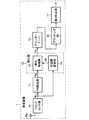
図1は、本発明に係る実施の形態1の受信装置1の構成例を概略的に示す機能ブロック図である。図1に示されるように、この受信装置1は、受信アンテナ素子Rx、フロントエンド部10、PN除去部11、等化部12、デインターリーバ15、デマッピング部16及び誤り訂正部17を備えている。
FIG. 1 is a functional block diagram schematically showing a configuration example of the
フロントエンド部10は、受信アンテナ素子Rxを介して無線信号を受信する。フロントエンド部10は、その無線信号に対して同調処理などのアナログ信号処理を施して搬送波帯域信号を生成し、さらにこの搬送波帯域信号にA/D変換及び直交復調を施してベースバンド受信信号(複素デジタル信号)Rsを生成し出力する。
The
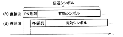
図2(A),(B)は、受信装置1で受信される複数の到来波(直接波と遅延波)の例を概略的に示す図である。図2に示されるように到来波は、既知信号系列であるPN系列と情報信号を含む有効シンボルとで構成される伝送シンボルを1単位として送信されたものである。ここで、PN(Pseudo−random Noise)系列は、疑似ランダム系列とも呼ばれており、連続した数百個のシンボル(時間領域信号)で構成されている。一方、有効シンボルは、単一搬送波を用いて情報を伝送するシングルキャリア変調方式で生成された信号群、あるいは、複数の搬送波(副搬送波)を用いて情報を伝送するマルチキャリア変調方式(特に、直交周波数分割多重化方式)で生成された信号群からなる。このような伝送シンボルのフォーマットは、たとえば、中国の地上デジタル放送規格であるDTMB(Digital Terrestrial Multimedia Broadcasting)規格で採用されている。
2A and 2B are diagrams schematically illustrating an example of a plurality of incoming waves (direct wave and delayed wave) received by the
PN除去部11は、ベースバンド受信信号Rsの系列からPN系列を除去し、ベースバンド受信信号Rsのうち有効シンボルのみの時間領域信号Re(以下、有効シンボル信号Reと呼ぶ。)を等化部12に出力する。
The
等化部12は、ベースバンド受信信号Rsの系列から伝送路特性(チャネルインパルス応答)を推定する伝送路推定部14と、伝送路推定部14から供給された伝送路特性の推定値Heを用いて有効シンボル信号Reに対して周波数軸等化(周波数領域での等化)を実行する等化処理部13とを有する。
The
図2(A),(B)に示されるように、受信装置1は、送信装置(図示せず)から直接到来した直接波と、建物などの障害物で反射、回折あるいは散乱を受けたために直接波に対して遅延して到来した遅延波とを受信する場合がある。この場合、直接波の伝送シンボルと遅延波の伝送シンボルとが重畳された信号を受信装置1は受信する。図2(B)には、遅延波が1つだけ示されているが、これに限定されない。2個以上の遅延波と直接波とが重畳された信号を受信装置1が受信する場合もある。等化部12は、遅延波の影響によるベースバンド受信信号Rsの歪み(位相回転量や振幅変化)を適正に補正する機能を有している。
As shown in FIGS. 2 (A) and 2 (B), the receiving
図1を参照すると、デインターリーバ15は、等化処理部13から出力された等化信号Esにデインターリブ処理を施す。デマッピング部16は、デインターリーバ15の出力にデマッピング処理を施す。具体的には、デマッピング部16は、送信装置で使用されたキャリア変調方式に従って、デインターリーバ15の出力(データシンボル)をビット列に変換する。キャリア変調方式としては、たとえば、QPSK(Quadrature Phase Shift Keying)や2M値QAM(Quadrature Amplitude Modulation;Mは正整数)といったデジタル変調方式が挙げられるが、これらに限定されるものではない。誤り訂正部17は、デマッピング部16の出力系列に対して、たとえば、公知のリードソロモン(Reed−Solomon)復号や畳み込み復号を施してデータ信号系列を生成し出力する。
Referring to FIG. 1, the
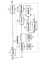
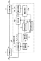
図3は、実施の形態1の伝送路推定部14の構成を概略的に示す機能ブロック図である。図3に示されるように、伝送路推定部14は、相関演算部21、PN系列生成部22、平滑化部26及び閾値処理部28を有する。伝送路推定部14は、さらに、到来波検出部23、変動量検出部24、区間設定部25及び閾値設定部27を有することを特徴とする。
FIG. 3 is a functional block diagram schematically showing the configuration of the transmission
PN系列生成部22は、ベースバンド受信信号Rsの系列として受信PN系列が入力されるとき、この受信PN系列に対応するPN系列を自己生成して相関演算部21に供給する。相関演算部21は、伝送シンボル毎にベースバンド受信信号RsとPN系列との相互相関を計算して相互相関値の系列(以下「相関系列」とも呼ぶ。)を得る。相互相関は、2つの信号波形のうち一方の信号波形を他方の信号波形に対して時間τだけ遅延させたときのずらし時間(遅延時間)τに関する関数として表現することができる。
When the received PN sequence is input as the baseband received signal Rs sequence, the PN
今、受信装置1への到来波が1つしか存在しないAWGN(Additive white Gaussian noise:白色ガウス雑音)伝送路の場合を想定する。遅延時間τに相当するサンプル番号を整数kとし、伝送シンボル番号を整数jとし、サンプル数を整数Lで表すとき、ベースバンド受信信号RsとPN系列との相関系列Rj(k)は、次式(1)で表現され得る。

ここで、pn(i−k)は、送信PN系列を示し、fj(i−k)は、j番目伝送シンボルにおける有効シンボル中の有効データ信号を表し、nj(i−k)は、j番目伝送シンボルが受けたガウス雑音を表し、pn(i)は、自己生成されたPN系列を表している。 Here, pn (ik) represents a transmission PN sequence, f j (ik) represents a valid data signal in a valid symbol in the jth transmission symbol, and n j (ik) represents It represents Gaussian noise received by the jth transmission symbol, and pn (i) represents a self-generated PN sequence.
上式(1)を整理すると、次式(2)を得ることができる。
ここで、式(2)の右辺第1項のδ(k)は、次式(3)で定義される。
上式(2)の右辺第1項のδ(k)は、到来波が受信装置1に到来した時刻に対応するk=0のときに非常に鋭い相関ピーク値を有し、k=0以外のときはほとんど零に近い値を有する関数である。
Δ (k) in the first term on the right side of the above equation (2) has a very sharp correlation peak value when k = 0 corresponding to the time when the incoming wave arrives at the receiving
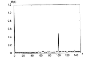
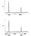
到来波が複数存在する場合には、受信装置1は、これら複数の到来波が互いに重畳された信号を受信するので、複数の到来波に対応する複数の時刻では複数の鋭いピークが相関系列に現れ、その他の時刻に対応する範囲では、上式(2)の右辺第2項に示したような雑音成分が相関系列に現れることとなる。図4は、2波モデル伝送路に対する相関系列R(k)の一例をグラフで示す図である。この2波モデル伝送路では、DU比(Desired to Undesired signal ratio)は6dB、遅延時間τに関するサンプル数は100サンプルとされた。図4において、k=0とk=100でそれぞれ主波と遅延波の受信レベルを示すピークが存在し、その他の範囲では、上式(1)の第2項の雑音成分が存在する。
When there are a plurality of arriving waves, the receiving
送信装置は、図2(A)に示したフォーマットを有する伝送シンボルを送信単位とした信号を送信するので、受信装置1の相関演算部21は、伝送シンボル間隔毎に相関系列R1(k),R2(k),R3(k),…を算出することとなる。これら相関系列R1(k),R2(k),R3(k),…は、平滑化部26と到来波検出部23とに与えられる。
Since the transmission apparatus transmits a signal with transmission symbols having the format shown in FIG. 2A as transmission units, the
到来波検出部23は、相関演算部21から出力される信号のサンプル毎の瞬時電力または振幅(相互相関値)に基づいて、各到来波に対応する相関ピーク値の位置を伝送シンボル毎に検出する機能を有する。具体的には、到来波検出部23は、相関系列から瞬時電力の分布を算出し、各瞬時電力を予め決められた閾値と比較し、この比較結果から閾値以上となった瞬時電力の位置と、この位置における瞬時電力を示す信号WDを出力する。なお、本実施の形態では、瞬時電力の値を示す信号WDが出力されるが、これに代えて振幅(相関ピーク値)を示す信号が出力されてもよい。
The incoming
変動量検出部24は、到来波検出部23から出力された信号WDに基づいて、各到来波の相関ピーク値(またはその瞬時電力)の時間変動を検出する機能を有する。変動量検出部24は、その検出結果を示す信号FDを平滑化部26と閾値設定部27とに与える。
The fluctuation
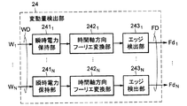
図5は、実施の形態1の変動量検出部24の構成を概略的に示す機能ブロック図である。図5に示されるように、この変動量検出部24は、N個の到来波にそれぞれ対応するN個の瞬時電力W1,…,W2を複数の伝送シンボル分保持するN個(Nは2以上の整数)の瞬時電力保持部(信号保持部)2411,…,241Nを含む。たとえば、図2(A),(B)に示したように到来波が2つ存在する場合には、直接波の瞬時電力(または振幅)の系列が瞬時電力保持部2411に保持され、遅延波の瞬時電力の系列は瞬時電力保持部2412に保持されればよい。ここで、瞬時電力保持部2411〜241Nの個数Nは、想定される到来波の数だけ必要となる。
FIG. 5 is a functional block diagram schematically showing the configuration of the fluctuation
変動量検出部24は、さらに、瞬時電力保持部2411,…,241Nからそれぞれ供給された瞬時電力に対して時間軸方向(シンボル方向)のフーリエ変換を実行してN個の周波数スペクトルを生成する時間軸方向フーリエ変換部2421,…,242Nと、これらN個の周波数スペクトルのエッジの周波数値(すなわち、最大ドップラー周波数)Fd1,…,FdNを検出するエッジ検出部2431,…,243Nとを含む。なお、時間軸方向フーリエ変換部2421,…,242Nに代えて、フーリエ変換以外の直交変換を行う処理部を使用してもよい。
Changing
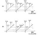
図6(A),(B)は、受信装置1が2波の到来波を受信する環境での相関系列(遅延プロファイル)を概略的に例示する図である。図6(A),(B)では、時刻T1,T2,T3にそれぞれ生成された相関系列が示されており、時刻T1の相関系列は、直接波と遅延波とにそれぞれ対応する相関ピーク値P1(1),P2(1)を有し、時刻T2の相関系列は、2つの相関ピーク値P1(2),P2(2)を有し、時刻T3の相関系列は、2つの相関ピーク値P1(3),P2(3)を有する。図6(A)は、送信装置に対して受信装置1が静止している場合、図6(B)は、受信装置1に対して受信装置1が移動している場合の相関系列をそれぞれ示す図である。受信装置1が静止している場合は、図6(A)に示されるように、いずれの時刻の相関系列の遅延プロファイル特性も同じである。これに対し、移動受信時には、図6(B)に示されるように、相関系列の遅延プロファイル特性は時々刻々と変化し、直接波及び遅延波のそれぞれの相関ピーク値及び位相は時間とともに変化する。
6A and 6B are diagrams schematically illustrating a correlation sequence (delay profile) in an environment in which the receiving
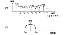
図7(A)は、j番目の到来波の相関ピーク値の時間軸方向(シンボル方向)の系列を概略的に例示する図であり、図7(B)は、図7(A)の相関ピーク値Pj(1),Pj(2),…の瞬時電力値をフーリエ変換して得られる周波数スペクトルを概略的に示す図である。図7(B)の周波数スペクトルは、−Fdj〜+Fdjの周波数範囲に分布している。この周波数スペクトルのエッジの周波数値(絶対値)Fdjは、最大ドップラー周波数と呼ばれている。 FIG. 7A is a diagram schematically illustrating a sequence in the time axis direction (symbol direction) of the correlation peak value of the j-th incoming wave, and FIG. 7B is a diagram illustrating the correlation of FIG. It is a figure which shows roughly the frequency spectrum obtained by Fourier-transforming the instantaneous electric power value of peak value Pj (1), Pj (2), .... The frequency spectrum in FIG. 7B is distributed in a frequency range of −Fd j to + Fd j . The frequency value (absolute value) Fd j of the edge of this frequency spectrum is called the maximum Doppler frequency.
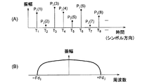
一方、図8(A)は、図7(A),(B)の場合とは異なる受信環境時での、j番目の到来波の相関ピーク値の時間軸方向(シンボル方向)の系列を概略的に例示する図であり、図8(B)は、図8(A)の相関ピーク値Pj(1),Pj(2),…の瞬時電力値をフーリエ変換して得られる周波数スペクトルを概略的に示す図である。図7(A)及び図8(A)に示されるように、図8(A)の場合の到来波が伝送路から受ける歪みは、図7(A)の場合の到来波が伝送路から受ける歪みよりも大きい。このため、図8(B)の周波数スペクトルは、図7(B)の周波数スペクトルよりも周波数方向に広い範囲(−Fdj〜+Fdj)に分布し、図7(B)の周波数スペクトルの最大ドップラー周波数よりも大きな最大ドップラー周波数を有している。 On the other hand, FIG. 8A schematically shows a time-axis direction (symbol direction) sequence of the correlation peak value of the j-th incoming wave in a reception environment different from those in FIGS. 7A and 7B. 8B is a frequency spectrum obtained by Fourier transforming the instantaneous power values of the correlation peak values P j (1), P j (2),... Of FIG. FIG. As shown in FIGS. 7A and 8A, the distortion that the incoming wave in the case of FIG. 8A receives from the transmission line is the distortion that the incoming wave in the case of FIG. 7A receives from the transmission line. Greater than distortion. Therefore, the frequency spectrum of FIG. 8B is distributed in a wider range (−Fd j to + Fd j ) in the frequency direction than the frequency spectrum of FIG. 7B, and the maximum of the frequency spectrum of FIG. It has a maximum Doppler frequency greater than the Doppler frequency.
たとえば、到来波の到来方向が受信装置1の移動方向と垂直の場合、最大ドップラー周波数はほぼ0Hzとなる。また、到来波の到来方向が受信装置1の移動方向と同じ場合には、その移動速度に対応した最大ドップラー周波数だけ周波数スペクトルが広がる。よって、受信装置1の相対移動速度が大きい程、到来波が伝送路から受ける歪みは大きくなる。このため、相対移動速度が大きい程、最大ドップラー周波数Fdjが大きくなる傾向がある。
For example, when the arrival direction of the incoming wave is perpendicular to the moving direction of the receiving
図5のエッジ検出部2431,…,243Nは、N個の到来波にそれぞれ対応する最大ドップラー周波数Fd1,…,FdNを検出することができる。これら最大ドップラー周波数Fd1,…,FdNを示す信号FDは、平滑化部26と閾値設定部27とに与えられる。
なお、本実施の形態では、変動量検出部24は、瞬時電力W1,…,WNに基づいて最大ドップラー周波数Fd1,…,FdNを検出しているが、これに代えて、相関ピーク値に基づいてドップラー周波数を検出するように構成されてもよい。また、本実施の形態では、変動量検出部24は、最大N個の到来波にそれぞれ対応するN個の瞬時電力系列を並列に処理する構成を有しているが、これに代えて、N個の瞬時電力系列を時分割処理して最大ドップラー周波数Fd1,…,FdNを検出するように構成されてもよい。時分割処理を採用することで、回路規模を小さくすることが可能となる。
In this embodiment, the fluctuation
区間設定部25は、到来波検出部23の出力に基づいて、相関系列に対して遅延時間方向に複数の区間を設定し、これら区間を示す信号SCを平滑化部26と閾値設定部27とに供給する機能を有する。各区間は、到来波検出部23で検出される複数の相関ピークのうちの少なくとも1つに対応するように定めてもよいし、あるいは、複数の相関ピーク値にそれぞれ対応し且つ互いに重複しないように複数の区間を定めることもできる。図9(A)は、2つの相関ピークにそれぞれ対応する区間A,Bを示す図である。また、図9(B)は、2つの相関ピークにそれぞれ対応する区間B,Dと、これら以外の区間A,C,Eとを示す図である。
The
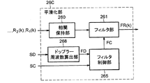
次に、平滑化部26は、区間設定部25により設定された区間毎に、複数の相関系列R1(k),R2(k),R3(k),…に対してシンボル方向の平滑化フィルタリングを実行して推定遅延プロファイルFR(k)を生成する機能を有する。平滑化部26は、最大ドップラー周波数Fd1,…,FdNを示す信号SDに基づいて、相関系列(相関ピーク値)の時間変動に追従するように自己の平滑化フィルタリング特性を変化させる機能をも有する。
Next, for each section set by the
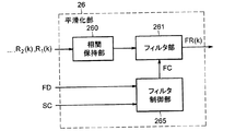
図10は、この平滑化部26の構成例を概略的に示す機能ブロック図である。図10に示されるように、平滑化部26は、複数の伝送シンボル分の相関系列R1(k),R2(k),R3(k),…を一時的に保持する相関保持部260と、この相関保持部260から読み出された複数の相関系列に対して区間ごとの平滑化フィルタリングを実行するフィルタ部261と、フィルタ制御部265とを含む。相関保持部260で保持される相関系列のデータ量は、後段のフィルタ部261のタップ数に依存する。たとえば、後段のフィルタ部261がTタップ(Tは正整数)を有するFIRフィルタの場合、Tシンボル分の相関系列を保持すればよい。
FIG. 10 is a functional block diagram schematically showing a configuration example of the smoothing
フィルタ制御部265は、信号FD,SCに応じて、フィルタ部261のフィルタ特性(平滑化フィルタリング特性)を区間変化や相関系列の時間変動に追従させるようにフィルタ部261のフィルタ係数群FCを設定する機能を有する。
The
具体的には、フィルタ制御部265は、最大ドップラー周波数が大きい程、フィルタ部261の通過帯域が広くなるように可変フィルタ係数群FCを設定することができる。なお、特許文献1に記載されている技術では、平滑化のフィルタ係数を変化させることができないため、最大ドップラー周波数の広がりの大きさが変化したとき、この変化にフィルタ特性を追従させることができない。
Specifically, the
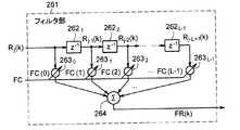
フィルタ部261としては、たとえば、公知のFIR(Finite Impulse Response)フィルタあるいはIIR(Infinite Impulse Response)フィルタなどのデジタルフィルタを使用すればよい。図11は、フィルタ部261の構成例を概略的に示す図である。図11に示されるように、フィルタ部261は、遅延素子2621〜262L−1と乗算器2630〜263L−1と総和演算器264とを含む。フィルタ部261は、可変フィルタ係数FC(0),FC(1),…,FC(L−1)と入力信号Rj(k),Rj−1(k),…,Rj−L+1(k)とを積和演算することにより推定遅延プロファイルFR(k)を算出することができる。区間設定部25により複数の区間が設定された場合には、フィルタ部261は、区間毎に可変フィルタ係数群FCを切り替えることで平滑化フィルタリングを区間毎に実行する。
As the
たとえば、フィルタ制御部265は、区間設定部25で決められた区間毎に、周波数スペクトルの広がりの大きさに相当する最大ドップラー周波数の2倍(=Fdj×2)の通過帯域を持たせるように可変フィルタ係数群FCを設定することができる。また、たとえば、図9(A)に示したように区間A,Bが設定されている場合には、区間Aの相関ピーク値の瞬時電力(または相関ピーク値)の最大ドップラー周波数がFa[Hz]の場合、2×Fa[Hz]の通過帯域のローパスフィルタ特性の可変フィルタ係数群FCを算出し、区間Bの相関ピーク値の瞬時電力(または相関ピーク値)の最大ドップラー周波数がFb[Hz]の場合には、2×Fb[Hz]の通過帯域のローパスフィルタ特性の可変フィルタ係数群FCを算出することができる。
For example, the
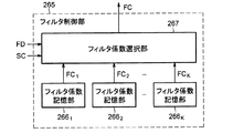
フィルタ制御部265は、可変フィルタ係数群FCを算出してもよいし、あるいは、予め用意された複数の可変フィルタ係数群の中から信号FD,SCに対応する可変フィルタ係数群FCを選択してもよい。図12は、予め用意された複数の可変フィルタ係数群の中から可変フィルタ係数群FCを選択する場合のフィルタ制御部265の構成例を概略的に示す機能ブロック図である。図12のフィルタ制御部265は、K個のフィルタ係数群FC1〜FCKを供給するK個のフィルタ係数記憶部2661,…,266Kと、信号FC,SCに応じて、フィルタ係数群FC1〜FCKの中から1つのフィルタ係数群FCを選択するフィルタ係数選択部267とを有する。
The
上記のように平滑化部26は、各到来波に対応する相関系列の時間変動に応じて平滑化フィルタリング特性を変化させるので、受信装置1の移動速度の変化に追随した可変フィルタ係数FCの制御を行うことができる。それ故、推定遅延プロファイルFR(k)の推定精度及び等化処理部13での等化精度を向上させることができる。また、複数の到来波にそれぞれ対応した複数の相関ピーク値が互いに別の区間に含まれるように相関系列の遅延時間を複数の区間に分割し、区間毎に独立に平滑化フィルタリング特性を設定するので、到来波毎に相関系列の時間変動量が異なる受信環境でも、推定遅延プロファイルFR(k)の推定精度及び等化処理部13での等化精度を向上させることができる。
As described above, the smoothing
なお、区間設定部25で設定された区間(たとえば、図9(B)の区間C)に相関ピーク値が存在しない場合は、フィルタ制御部265は、たとえば、最も通過帯域を狭くする可変フィルタ係数FCを選択すればよい。
Note that if the correlation peak value does not exist in the section set by the section setting section 25 (for example, section C in FIG. 9B), the
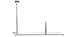
閾値処理部28は、平滑化部26の出力から閾値Th1未満の値を切り捨てる閾値処理を実行する機能を有する。具体的には、閾値処理部28は、平滑化部26の出力FR(k)の瞬時電力(または振幅)を閾値Th1と比較し、瞬時電力(または振幅)が当該閾値Th1より大きい場合は、平滑化部26の出力をそのまま等化処理部13に出力し、瞬時電力(または振幅)が当該閾値Th1以下の場合は、零値を出力することができる。ここで、閾値Th1より大きいサンプル値の前後の任意個数のサンプル値を零値に置き換えず、平滑化部26の出力をそのまま等化処理部13に出力してもよい。図13は、2波モデル伝送路に対する閾値処理部28の出力の一例を概略的に示すグラフである。
The
また、閾値処理部28は、区間設定部25で設定された区間毎に閾値処理部28で使用される閾値Th1を設定する機能をも有する。また、閾値設定部27は、その閾値Th1を最大ドップラー周波数に応じた値に設定する機能を有する。たとえば、最大ドップラー周波数Fdjの値が小さいために平滑化部26で狭い通過帯域の平滑化フィルタが使用される区間では、閾値Th1を基準値よりも低い値に設定することができ、一方で、最大ドップラー周波数Fdjの値が大きいために平滑化部26で広い通過帯域の平滑化フィルタが使用される区間では、閾値Th1を基準値よりも高い値に設定することができる。ここで、基準値としては、平滑化部26の最大出力値(ピーク値)よりも小さい値が使用される。このように、各区間で用いられる平滑化フィルタの通過帯域に応じて閾値Th1を設定することにより、受信レベルの小さな到来波を閾値処理で切り捨てることなく遅延プロファイルを推定することができるため、等化処理部13での等化精度を向上させることができる。
The
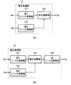
等化処理部13は、閾値処理の実行後の当該推定遅延プロファイルを伝送路推定値Heとして用いて受信信号Reの歪みを補正することができる。図14(A)は、受信信号Reがマルチキャリア変調方式で生成された場合の等化処理部13の構成を概略的に示す図であり、図14(B)は、受信信号Reがシングルキャリア変調方式で生成された場合の等化処理部13の構成を概略的に示す図である。
The
図14(A)に示されるように、受信信号ReがOFDM信号のようなマルチキャリア信号である場合には、等化処理部13は、受信信号Reをフーリエ変換して周波数領域の信号を生成する第1フーリエ変換部131と、伝送路推定値をフーリエ変換して周波数領域の伝送路推定値を生成する第2フーリエ変換部132と、第1フーリエ変換部131の出力を第2フーリエ変換部132の出力で除算して等化信号Esを生成する等化演算部133とを有する。一方、受信信号ReがOFDM信号のようなマルチキャリア信号である場合には、図14(B)に示されるように受信信号Reがシングルキャリア変調方式で生成された場合には、等化処理部13は、第1フーリエ変換部131、第2フーリエ変換部132及び等化演算部133に加えて、等化演算部133の出力を逆フーリエ変換して等化信号Esを生成する逆フーリエ変換部134を有している。
As shown in FIG. 14A, when the received signal Re is a multicarrier signal such as an OFDM signal, the
以上に説明したように実施の形態1では、平滑化部26は、相関系列の時間変動に追従して平滑化フィルタリング特性を変化させことができるので、伝送路特性が時間とともに変化する環境下でも、推定遅延プロファイルFR(k)の推定精度の低下を抑制することができる。しかも、平滑化部26は、複数の到来波にそれぞれ対応する区間毎に個別に平滑化フィルタリング特性を変化させて区間毎の平滑化を実行することができるため、遅延プロファイルの推定を高い精度で行うことが可能である。したがって、従来技術と比べると、等化処理部13での等化精度を向上させることができる。
As described above, in the first embodiment, the smoothing
実施の形態2.
次に、本発明に係る実施の形態2について説明する。図15は、実施の形態2の伝送路推定部14Bの構成を概略的に示す機能ブロック図である。本実施の形態の受信装置の構成は、伝送路推定部14Bを除いて、実施の形態1の受信装置1の構成と同じである。
Next, a second embodiment according to the present invention will be described. FIG. 15 is a functional block diagram schematically showing the configuration of the transmission
また、図15に示されるように、本実施の形態の伝送路推定部14Bの構成は、変動量検出部24B、平滑化部26B及び閾値設定部27Bを除いて、実施の形態1の伝送路推定部14(図3)の構成と同じである。
Also, as shown in FIG. 15, the configuration of the transmission
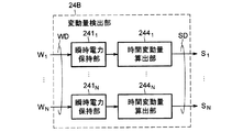
図16は、実施の形態2の変動量検出部24Bの構成を概略的に示す機能ブロック図である。変動量検出部24Bは、実施の形態1の変動量検出部24と同様に、N個の到来波にそれぞれ対応するN個の瞬時電力W1,…,W2を複数の伝送シンボル分保持するN個の瞬時電力保持部(信号保持部)2411,…,241Nを含む。変動量検出部24Bは、さらに、瞬時電力保持部2411,…,241Nに保持されている瞬時電力W1,…,WNのそれぞれの時間変動量S1,…,SNを検出する時間変動量算出部2441,…,244Nを含んでいる。時間変動量S1,…,SNを示す信号SDは、平滑化部26Bと閾値設定部27Bとに供給される。
FIG. 16 is a functional block diagram schematically showing the configuration of the fluctuation
j番目の到来波に対応する時間変動量算出部244jは、たとえば、瞬時電力Wjの時間変化量の絶対値の平均値を時間変動量Sjとして算出することができる。ここで、瞬時電力Wjに代えて、相関ピーク値Pjを使用して時間変動量Sjを算出してもよい。
The time
今、j番目の到来波に対応する相関ピーク値をPj(q)(qは、現在時刻Tqを表す番号)で表すとき、j番目の到来波に対応する瞬時電力Wj(q)は、たとえば、相関ピーク値Pj(q)とその複素共役Pj(q)*との積で与えられる。具体的には、次式(4)に従って瞬時電力Wj(q)を計算することができる。
現在時刻Tqでの時間変動量Sj(q)は、たとえば、シンボル方向に連続するM個の瞬時電力Wj(q),Wj(q−1),…,Wj(q−M+1)を用いて次式(5)に従って算出することができる。
上式(5)の瞬時電力Wjに代えて相関ピーク値Pjが使用される場合には、上式(5)に代えて次式(6)に従って時間変動量Sj(q)を算出することができる。
あるいは、上記上式(6)の相関ピーク値Pjに代えて、相関ピークPjの絶対値(相関ピーク絶対値)が使用される場合には、次式(7)に従って時間変動量Sj(q)を算出することができる。
上式(5),(6)または(7)による演算は、たとえば、タップ数Mの移動平均フィルタを用いて実現することが可能である。 The calculation according to the above formula (5), (6) or (7) can be realized by using, for example, a moving average filter having M taps.
なお、上式(5)は、シンボル方向に連続する瞬時電力の差分絶対値の2乗の移動平均を算出する式であるが、これに代えて、シンボル方向に連続する瞬時電力の差分絶対値の移動平均を算出する式を用いてもよい。同様に、上式(6)は、シンボル方向に連続する相関ピーク値の差分絶対値の2乗の移動平均を算出する式であるが、これに代えて、シンボル方向に連続する相関ピーク値の差分絶対値の移動平均を算出する式を用いてもよい。同様に、上式(7)は、シンボル方向に連続する相関ピーク絶対値の差分絶対値の2乗の移動平均を算出する式であるが、これに代えて、シンボル方向に連続する相関ピーク絶対値の差分絶対値の移動平均を算出する式を用いてもよい。 The above equation (5) is an equation for calculating the moving average of the square of the difference absolute value of the instantaneous power continuous in the symbol direction. Instead, the absolute value of the difference of instantaneous power continuous in the symbol direction is used instead. An equation for calculating the moving average of the above may be used. Similarly, the above equation (6) is an equation for calculating the moving average of the squares of the absolute difference values of the correlation peak values continuous in the symbol direction, but instead of the correlation peak values continuous in the symbol direction. An equation for calculating a moving average of absolute differences may be used. Similarly, the above equation (7) is an equation for calculating the moving average of the squares of the absolute differences of the correlation peak absolute values continuous in the symbol direction, but instead of the correlation peak absolute values continuous in the symbol direction. You may use the formula which calculates the moving average of the difference absolute value of a value.
平滑化部26Bは、実施の形態1の平滑化部26と同様に、区間毎に、相関系列R1(k),R2(k),R3(k),…に対してシンボル方向の平滑化フィルタリングを実行して推定遅延プロファイルFR(k)を生成する機能を有する。本実施の形態の平滑化部26Bは、さらに、時間変動量S1,…,SNに基づいて、相関系列(相関ピーク値)の時間変動に追従するように自己の平滑化フィルタリング特性を変化させる機能を有している。
As with the smoothing
なお、本実施の形態では、変動量検出部24Bは、瞬時電力W1,…,WNに基づいて時間変動量S1,…,SNを検出しているが、これに代えて、相関ピーク値に基づいて時間変動量S1,…,SNを検出するように構成されてもよい。また、本実施の形態では、変動量検出部24Bは、最大N個の到来波にそれぞれ対応するN個の瞬時電力系列を並列に処理する構成を有しているが、これに代えて、N個の瞬時電力系列を時分割処理して時間変動量S1,…,SNを検出するように構成されてもよい。時分割処理を採用することで、回路規模を小さくすることが可能となる。
In the present embodiment, the fluctuation
次に、図17は、実施の形態2の平滑化部26Bの構成例を概略的に示す機能ブロック図である。この平滑化部26Bの構成は、フィルタ制御部265Bを除いて、実施の形態1の平滑化部26の構成と同じである。本実施の形態のフィルタ制御部265Bは、信号SD,SCに応じて、フィルタ部261のフィルタ特性(平滑化フィルタリング特性)を区間変化や相関系列の時間変動に追従させるようにフィルタ部261のフィルタ係数群FCを設定する機能を有する。具体的には、フィルタ制御部265Bは、区間設定部25で決められた区間毎に、時間変動量Sjが大きい程、フィルタ部261の通過帯域が広くなるようにフィルタ係数群FCを設定することができる。
Next, FIG. 17 is a functional block diagram schematically showing a configuration example of the smoothing
閾値設定部27Bは、実施の形態1の閾値設定部27と同様に、区間設定部25で設定された区間毎に閾値処理部28で使用される閾値Th1を設定する機能を有し、さらに、その閾値Th1を上記時間変動量Sjに応じた値に設定する機能を有する。たとえば、時間変動量Sjが小さいために平滑化部26で狭い通過帯域の平滑化フィルタが使用された区間では、閾値Th1を基準値(平滑化部26の出力のピーク値よりも小さい値)よりも低い値に設定することができ、一方で、時間変動量Sjが大きいために平滑化部26で広い通過帯域の平滑化フィルタが使用された区間では、閾値Th1を基準値よりも高い値に設定することができる。
Like the
以上に説明したように実施の形態2では、平滑化部26Bは、相関系列の時間変動に追従して平滑化フィルタリング特性を変化させことができるので、伝送路特性が時間とともに変化する環境下でも、推定遅延プロファイルFR(k)の推定精度の低下を抑制することができる。しかも、平滑化部26Bは、複数の到来波にそれぞれ対応する区間毎に個別に平滑化フィルタリング特性を変化させて区間毎の平滑化を実行することができるため、遅延プロファイルの推定を高い精度で行うことが可能である。したがって、従来技術と比べると、等化処理部13での等化精度を向上させることができる。
As described above, in the second embodiment, the smoothing
実施の形態3.
次に、本発明に係る実施の形態3について説明する。図18は、実施の形態3の平滑化部26Cの構成を概略的に示す機能ブロック図である。本実施の形態の伝送路推定部の構成は、この平滑化部26Cを除いて、実施の形態2の伝送路推定部14B(図15)の構成と同じである。また、本実施の形態の受信装置の構成は、平滑化部26Cを除いて、実施の形態2の受信装置の構成と同じである。
Next, a third embodiment according to the present invention will be described. FIG. 18 is a functional block diagram schematically showing the configuration of the smoothing
図18に示されるように、平滑化部26Cは、実施の形態1の平滑化部26(図10)と同様に相関保持部260、フィルタ部261及びフィルタ制御部265を有する。本実施の形態の平滑化部26Cは、さらに、上記時間変動量S1,…,SNを上記最大ドップラー周波数Fd1,…,FdNにそれぞれ変換するドップラー周波数算出部268を有している。このため、フィルタ制御部265は、最大ドップラー周波数Fd1,…,FdNに応じて区間毎にフィルタ係数群FCを設定することができる。
As illustrated in FIG. 18, the smoothing
ドップラー周波数算出部268は、時間変動量の値と最大ドップラー周波数の値との間の関係を一意に定めるルックアップテーブル(変換テーブル)を有することができる。この場合、ドップラー周波数算出部268は、ルックアップテーブルを参照して、入力された時間変動量Sjの値に対応する最大ドップラー周波数Fdjの値を出力することが可能である。このようなドップラー周波数算出部268は、時間変動量Sjをアドレス入力とし、このアドレス入力に対応する記憶データの値を最大ドップラー周波数Fdjの値として出力するメモリ回路を用いて実現することができる。
The Doppler
あるいは、ドップラー周波数算出部268は、時間変動量Sjを独立変数(引数)とする所定の単調増加関数を用いた演算により、入力された時間変動量Sjから最大ドップラー周波数Fdjを算出してもよい。たとえば、次式(8)に示すような1次関数を用いて最大ドップラー周波数Fdjを算出することができる。
![]()
![]()
ここで、α,βは、定数である(ただし、α>0)。 Here, α and β are constants (where α> 0).
実施の形態3の場合も、実施の形態1,2の場合と同様の効果を得ることができる。 In the third embodiment, the same effect as in the first and second embodiments can be obtained.
以上、図面を参照して本発明に係る種々の実施の形態について述べたが、これらは本発明の例示であり、上記以外の様々な形態を採用することもできる。 Although various embodiments according to the present invention have been described above with reference to the drawings, these are examples of the present invention, and various forms other than the above can be adopted.
上記実施の形態1乃至3の受信装置の機能の一部は、ハードウェア構成で実現されてもよいし、あるいは、CPUを含むマイクロプロセッサにより実行されるコンピュータプログラムで実現されてもよい。当該機能の一部がコンピュータプログラムで実現される場合には、マイクロプロセッサは、コンピュータ読み取り可能な記録媒体から当該コンピュータプログラムをロードし実行することによって当該機能の一部を実現することができる。 Part of the functions of the receiving apparatuses according to the first to third embodiments may be realized by a hardware configuration, or may be realized by a computer program executed by a microprocessor including a CPU. When a part of the function is realized by a computer program, the microprocessor can realize a part of the function by loading and executing the computer program from a computer-readable recording medium.
また、上記実施の形態1乃至3の受信装置の構成の全部または一部は、LSI(Large Scale Integrated circuit)で実現することができる。また、FPGA(Field−Programmable Gate Array)やASIC(Application Specific Integrated Circuit)により実施の形態1乃至3の受信装置の構成の全部または一部を実現することも可能である。 Further, all or part of the configuration of the receiving apparatus according to the first to third embodiments can be realized by an LSI (Large Scale Integrated circuit). It is also possible to realize all or part of the configuration of the receiving apparatus according to the first to third embodiments by an FPGA (Field-Programmable Gate Array) or an ASIC (Application Specific Integrated Circuit).
さらに、上記実施の形態1乃至3の受信装置は、ディジタル放送受信装置(テレビジョン放送受信機及び音声放送受信機を含む。)、無線LAN機器、電力線通信(PLC:Power−Line Communication)システムの受信装置、あるいは、移動体通信システムの受信端末といった通信装置として構成されてもよい。 Further, the receivers of the first to third embodiments are digital broadcast receivers (including television broadcast receivers and audio broadcast receivers), wireless LAN devices, and power line communication (PLC: Power-Line Communication) systems. You may comprise as communication apparatuses, such as a receiving device or the receiving terminal of a mobile communication system.
1 受信装置、 10 フロントエンド部、 11 PN除去部(既知信号除去部)、 12 等化部、 13 等化処理部、 14,14B 伝送路推定部、 15 デインターリーバ、 16 デマッピング部、 17 誤り訂正部、 21 相関演算部、 22 PN系列生成部(既知信号系列生成部)、 23 到来波検出部、 24,24B 変動量検出部、 2411〜241N 瞬時電力保持部(信号保持部)、 2421〜242N 時間軸方向フーリエ変換部、 2431〜243N エッジ検出部、 2441〜244N 時間変動量算出部、 25 区間設定部、 26,26B,26C 平滑化部、 260 相関保持部、 261 フィルタ部、 265,265B フィルタ制御部(フィルタ係数設定部)、 2661〜266K フィルタ係数記憶部、 267 フィルタ係数選択部、 268 ドップラー周波数算出部、 27,27B 閾値設定部、 28 閾値処理部。
DESCRIPTION OF
Claims (13)
既知信号系列を供給する既知信号系列生成部と、
前記伝送シンボル毎に前記既知信号系列と前記受信信号との間の相互相関を計算して相互相関値の系列を得る相関演算部と、
前記相互相関値の系列から、当該受信装置で受信された複数の到来波にそれぞれ対応する複数の相関ピーク値の位置を前記伝送シンボル毎に検出する到来波検出部と、
前記相互相関値のそれぞれの位置に基づいて、前記相互相関値の系列に対して、前記複数の相関ピーク値のうちの少なくとも1つに対応する区間を含む、複数の区間を設定する区間設定部と、
前記複数の相関ピーク値の時間変動を検出する変動量検出部と、
前記相互相関値の系列に対してシンボル方向の平滑化フィルタリングを前記複数の区間の区間毎に実行して推定遅延プロファイルを生成するフィルタ部と、
前記変動量検出部により検出された当該時間変動に応じて前記フィルタ部の平滑化フィルタリング特性を前記複数の区間の区間毎に変化させるフィルタ制御部と、
前記推定遅延プロファイルに基づいて前記受信信号の歪みを補正する等化処理を実行する等化処理部と
を備え、
前記フィルタ制御部は、前記時間変動が大きい程、前記フィルタ部の通過帯域が広くなるように前記平滑化フィルタリング特性を変化させる
ことを特徴とする等化装置。 An equalizer for correcting distortion of a received signal of a transmission symbol received by a receiver when a transmission symbol having a known signal sequence and an effective symbol including an information signal is continuously transmitted from the transmitter. And
A known signal sequence generator for supplying a known signal sequence;
A correlation calculation unit for calculating a cross-correlation between the known signal sequence and the received signal for each transmission symbol to obtain a sequence of cross-correlation values;
An incoming wave detector that detects, for each transmission symbol, a position of a plurality of correlation peak values respectively corresponding to a plurality of incoming waves received by the receiving device from the series of cross-correlation values;
A section setting unit that sets a plurality of sections including a section corresponding to at least one of the plurality of correlation peak values for the series of cross correlation values based on the respective positions of the cross correlation values. When,
A fluctuation amount detector for detecting temporal fluctuations of the plurality of correlation peak values;
A filter unit that performs smoothing filtering in a symbol direction on the cross-correlation value series for each of the sections to generate an estimated delay profile;
A filter control unit that changes the smoothing filtering characteristic of the filter unit for each of the sections according to the time variation detected by the variation amount detection unit;
An equalization processing unit that executes an equalization process for correcting distortion of the received signal based on the estimated delay profile;
The said filter control part changes the said smoothing filtering characteristic so that the pass band of the said filter part becomes wide, so that the said time fluctuation is large, The equalization apparatus characterized by the above-mentioned.
前記フィルタ部により生成された推定遅延プロファイルから閾値未満の値を切り捨てる閾値処理を実行する閾値処理部と、
前記変動量検出部により検出された当該時間変動に応じて前記閾値を変化させる閾値設定部と
をさらに備え、
前記等化処理部は、前記閾値処理の実行後の当該推定遅延プロファイルに基づいて前記受信信号の歪みを補正する
ことを特徴とする等化装置。 The equalization apparatus according to claim 1 or 2 ,
A threshold processing unit that executes threshold processing for truncating a value less than the threshold from the estimated delay profile generated by the filter unit;
A threshold setting unit that changes the threshold according to the time variation detected by the variation detection unit;
The equalization apparatus, wherein the equalization processing unit corrects distortion of the received signal based on the estimated delay profile after the threshold processing is executed.
前記変動量検出部は、
前記複数の相関ピーク値の各々の瞬時電力または相関ピーク値を複数の伝送シンボル分保持する信号保持部と、
前記瞬時電力または前記相関ピーク値を前記複数の伝送シンボルに亘ってサンプリングし、当該サンプリングされた瞬時電力または相関ピーク値を直交変換して周波数スペクトルを生成する直交変換部と、
前記周波数スペクトルのエッジの周波数値を検出するエッジ検出部と
を含み、
前記フィルタ制御部は、前記エッジの周波数値に応じて前記平滑化フィルタリング特性を変化させる
ことを特徴とする等化装置。 The equalization apparatus according to claim 1 or 2 ,
The fluctuation amount detection unit
A signal holding unit that holds the instantaneous power or the correlation peak value of each of the plurality of correlation peak values for a plurality of transmission symbols;
An orthogonal transform unit that samples the instantaneous power or the correlation peak value over the plurality of transmission symbols and orthogonally transforms the sampled instantaneous power or the correlation peak value to generate a frequency spectrum;
An edge detector for detecting a frequency value of an edge of the frequency spectrum,
The said filter control part changes the said smoothing filtering characteristic according to the frequency value of the said edge, The equalization apparatus characterized by the above-mentioned.
前記フィルタ部により生成された推定遅延プロファイルから閾値未満の値を切り捨てる閾値処理を実行する閾値処理部と、
前記閾値を前記エッジの周波数値に応じた値に設定する閾値設定部と
をさらに備え、
前記閾値設定部は、前記エッジの周波数値が小さい程、前記閾値を小さくし、
前記等化処理部は、前記閾値処理の実行後の当該推定遅延プロファイルに基づいて前記受信信号の歪みを補正する
ことを特徴とする等化装置。 The equalization apparatus according to claim 5 , wherein
A threshold processing unit that executes threshold processing for truncating a value less than the threshold from the estimated delay profile generated by the filter unit;
A threshold setting unit that sets the threshold to a value corresponding to the frequency value of the edge;
The threshold value setting unit decreases the threshold value as the frequency value of the edge is smaller.
The equalization apparatus, wherein the equalization processing unit corrects distortion of the received signal based on the estimated delay profile after the threshold processing is executed.
前記変動量検出部は、
前記複数の到来波の各々に対応する当該相関ピーク値または当該相関ピーク値の瞬時電力を複数の伝送シンボル分保持する信号保持部と、
前記信号保持部に保持されている当該瞬時電力または当該相関ピーク値の時間変動量を検出する時間変動量算出部と
を含み、
前記フィルタ制御部は、前記時間変動量算出部により検出された前記時間変動量に応じて前記平滑化フィルタリング特性を変化させる
ことを特徴とする等化装置。 The equalization apparatus according to claim 1 or 2 ,
The fluctuation amount detection unit
A signal holding unit for holding the correlation peak value corresponding to each of the plurality of incoming waves or the instantaneous power of the correlation peak value for a plurality of transmission symbols;
A time fluctuation amount calculating unit that detects a time fluctuation amount of the instantaneous power or the correlation peak value held in the signal holding unit,
The said filter control part changes the said smoothing filtering characteristic according to the said time fluctuation amount detected by the said time fluctuation amount calculation part, The equalization apparatus characterized by the above-mentioned.
前記変動量検出部の出力に基づいて最大ドップラー周波数を算出するドップラー周波数算出部をさらに備え、
前記変動量検出部は、
前記複数の到来波の各々に対応する当該相関ピーク値または当該相関ピーク値の瞬時電力を複数の伝送シンボル分保持する信号保持部と、
前記信号保持部に保持されている当該瞬時電力または当該相関ピーク値の時間変動量を検出する時間変動量算出部と
を含み、
前記ドップラー周波数算出部は、前記時間変動量に基づいて前記最大ドップラー周波数を算出し、
前記フィルタ制御部は、前記最大ドップラー周波数に応じて前記平滑化フィルタリング特性を変化させる
ことを特徴とする等化装置。 The equalization apparatus according to claim 1 or 2 ,
Further comprising a Doppler frequency calculation unit for calculating a maximum Doppler frequency based on the output of the fluctuation amount detection unit;
The fluctuation amount detection unit
A signal holding unit for holding the correlation peak value corresponding to each of the plurality of incoming waves or the instantaneous power of the correlation peak value for a plurality of transmission symbols;
A time fluctuation amount calculating unit that detects a time fluctuation amount of the instantaneous power or the correlation peak value held in the signal holding unit,
The Doppler frequency calculation unit calculates the maximum Doppler frequency based on the amount of time variation,
The equalizing apparatus, wherein the filter control unit changes the smoothing filtering characteristic according to the maximum Doppler frequency.
前記フィルタ部により生成された推定遅延プロファイルから閾値未満の値を切り捨てる閾値処理を実行する閾値処理部と、
前記閾値を前記時間変動量に応じた値に設定する閾値設定部と
をさらに備え、
前記閾値設定部は、前記時間変動量が小さい程、前記閾値を小さくし、
前記等化処理部は、前記閾値処理の実行後の当該推定遅延プロファイルに基づいて前記受信信号の歪みを補正する
ことを特徴とする等化装置。 The equalization apparatus according to claim 9 , wherein
A threshold processing unit that executes threshold processing for truncating a value less than the threshold from the estimated delay profile generated by the filter unit;
A threshold setting unit that sets the threshold to a value according to the amount of time variation,
The threshold value setting unit decreases the threshold value as the time variation amount decreases.
The equalization apparatus, wherein the equalization processing unit corrects distortion of the received signal based on the estimated delay profile after the threshold processing is executed.
前記フィルタ部は、可変フィルタ係数群を有するデジタルフィルタであり、
前記フィルタ制御部は、前記可変フィルタ係数群の値を更新することで前記平滑化フィルタリング特性を変化させる
ことを特徴とする等化装置。 The equalization apparatus according to any one of claims 1 to 10 , wherein
The filter unit is a digital filter having a variable filter coefficient group,
The said filter control part changes the said smoothing filtering characteristic by updating the value of the said variable filter coefficient group, The equalization apparatus characterized by the above-mentioned.
前記信号受信部で受信された当該受信信号の歪みを補正する請求項1から11のうちのいずれか1項に記載の等化装置と
を備えることを特徴とする受信装置。 A signal receiving unit that receives a signal of the transmission symbol when a transmission symbol having a known signal sequence and an effective symbol including an information signal is continuously transmitted from the transmission device;
Receiving apparatus characterized by comprising equalization device according to any one of claims 1 to 11 for correcting the distortion of the received the received signal in the signal receiving unit.
前記伝送シンボル毎に前記既知信号系列と前記受信信号との間の相互相関を計算して相互相関値の系列を得るステップと、
前記相互相関値の系列から、当該受信装置で受信された複数の到来波にそれぞれ対応する複数の相関ピーク値の位置を前記伝送シンボル毎に検出するステップと、
前記相互相関値のそれぞれの位置に基づいて、前記相互相関値の系列に対して、前記複数の相関ピーク値のうちの少なくとも1つに対応する区間を含む、複数の区間を設定するステップと、
前記複数の相関ピーク値の時間変動を検出するステップと、
前記相互相関値の系列に対してシンボル方向の平滑化フィルタリングを前記複数の区間の区間毎に実行して推定遅延プロファイルを生成するステップと、
当該検出された時間変動に応じて前記平滑化フィルタリングの特性を前記複数の区間の区間毎に変化させるステップと、
前記推定遅延プロファイルに基づいて前記受信信号の歪みを補正するステップと
を備え、
前記平滑化フィルタリングの特性を変化させる前記ステップは、前記時間変動が大きい程、前記平滑化フィルタリングにおける通過帯域が広くなるように前記平滑化フィルタリングの特性を変化させる
ことを特徴とする等化方法。 This is an equalization method for correcting distortion of a received signal of a transmission symbol received by a receiving device when a transmission symbol having a known signal sequence and an effective symbol including an information signal is continuously transmitted from the transmitting device. And
Calculating a cross-correlation between the known signal sequence and the received signal for each transmission symbol to obtain a sequence of cross-correlation values;
Detecting a position of a plurality of correlation peak values respectively corresponding to a plurality of incoming waves received by the receiving device from the cross-correlation value sequence for each transmission symbol;
Setting a plurality of sections including a section corresponding to at least one of the plurality of correlation peak values for the series of cross-correlation values based on the respective positions of the cross-correlation values;
Detecting time variations of the plurality of correlation peak values;
Performing a smoothing filtering in a symbol direction on the cross-correlation value series for each of the sections to generate an estimated delay profile;
Changing the characteristics of the smoothing filtering for each section of the plurality of sections according to the detected temporal variation;
Correcting distortion of the received signal based on the estimated delay profile,
The equalizing method characterized in that the step of changing the characteristics of the smoothing filtering changes the characteristics of the smoothing filtering so that a pass band in the smoothing filtering becomes wider as the time variation is larger.
Priority Applications (2)
| Application Number | Priority Date | Filing Date | Title |
|---|---|---|---|
| JP2012057811A JP5896795B2 (en) | 2012-03-14 | 2012-03-14 | Equalizer, receiver, and equalization method |
| CN201210557407.5A CN103312643B (en) | 2012-03-14 | 2012-12-20 | Balancer, receiving system and equalization methods |
Applications Claiming Priority (1)
| Application Number | Priority Date | Filing Date | Title |
|---|---|---|---|
| JP2012057811A JP5896795B2 (en) | 2012-03-14 | 2012-03-14 | Equalizer, receiver, and equalization method |
Publications (3)
| Publication Number | Publication Date |
|---|---|
| JP2013192107A JP2013192107A (en) | 2013-09-26 |
| JP2013192107A5 JP2013192107A5 (en) | 2015-02-12 |
| JP5896795B2 true JP5896795B2 (en) | 2016-03-30 |
Family
ID=49137435
Family Applications (1)
| Application Number | Title | Priority Date | Filing Date |
|---|---|---|---|
| JP2012057811A Expired - Fee Related JP5896795B2 (en) | 2012-03-14 | 2012-03-14 | Equalizer, receiver, and equalization method |
Country Status (2)
| Country | Link |
|---|---|
| JP (1) | JP5896795B2 (en) |
| CN (1) | CN103312643B (en) |
Families Citing this family (7)
| Publication number | Priority date | Publication date | Assignee | Title |
|---|---|---|---|---|
| JP5710534B2 (en) * | 2012-03-27 | 2015-04-30 | 株式会社東芝 | Frequency domain equalizer and receiver |
| JP5995703B2 (en) * | 2012-12-19 | 2016-09-21 | 三菱電機株式会社 | Equalizer, equalization method, and receiver |
| JP6198665B2 (en) | 2013-07-05 | 2017-09-20 | 三菱電機株式会社 | Receiving apparatus and receiving method |
| JP6293011B2 (en) * | 2013-11-21 | 2018-03-14 | 三菱電機株式会社 | Equalizer, equalization method, and receiver |
| US9929758B2 (en) * | 2015-07-27 | 2018-03-27 | Futurewei Technologies, Inc. | Reducing receiver distortion caused by transmitter signals |
| CN111953624A (en) * | 2019-05-17 | 2020-11-17 | 中兴通讯股份有限公司 | Echo time delay estimation method and device |
| CN113381958B (en) * | 2020-02-25 | 2022-07-08 | 大唐移动通信设备有限公司 | Method and device for adjusting self-adaptive peak threshold |
Family Cites Families (16)
| Publication number | Priority date | Publication date | Assignee | Title |
|---|---|---|---|---|
| JPH1051356A (en) * | 1996-03-29 | 1998-02-20 | Matsushita Electric Ind Co Ltd | Doppler frequency measurement circuit and synchronization circuit |
| US5903596A (en) * | 1996-05-16 | 1999-05-11 | Nakano; Takayuki | Spread spectrum demodulation unit |
| JP3146196B2 (en) * | 1999-03-17 | 2001-03-12 | 株式会社次世代デジタルテレビジョン放送システム研究所 | OFDM demodulator |
| JP2001251216A (en) * | 2000-03-06 | 2001-09-14 | Oki Electric Ind Co Ltd | Circuit and method for capturing synchronization |
| JP2002094412A (en) * | 2000-09-14 | 2002-03-29 | Matsushita Electric Ind Co Ltd | Cdma receiving device and method for processing reception |
| JP2002111549A (en) * | 2000-10-02 | 2002-04-12 | Canon Inc | Synchronizer |
| JP2002141885A (en) * | 2000-10-31 | 2002-05-17 | Mitsubishi Electric Corp | Ofdm receiver |
| JP2002261658A (en) * | 2001-03-02 | 2002-09-13 | Matsushita Electric Ind Co Ltd | Receiving apparatus and pass selection method |
| JP4165238B2 (en) * | 2003-01-29 | 2008-10-15 | 日本電気株式会社 | Path search circuit, method and program |
| JP4816353B2 (en) * | 2006-09-12 | 2011-11-16 | ソニー株式会社 | OFDM receiving apparatus and OFDM signal receiving method |
| CN101232480B (en) * | 2006-10-05 | 2012-09-05 | 马维尔国际贸易有限公司 | Method and device for regulating frequency offset |
| JP5042118B2 (en) * | 2008-05-20 | 2012-10-03 | 三菱電機株式会社 | Transmission path estimation apparatus and method |
| JP5338409B2 (en) * | 2009-03-19 | 2013-11-13 | 三菱電機株式会社 | Delay profile estimation device and image display device |
| JP4975085B2 (en) * | 2009-11-09 | 2012-07-11 | 三菱電機株式会社 | Receiving apparatus and method |
| JP2011199391A (en) * | 2010-03-17 | 2011-10-06 | Toshiba Corp | Response estimator of transmission line |
| JP4851637B1 (en) * | 2011-05-16 | 2012-01-11 | パナソニック株式会社 | Equalizer and equalization method |
-
2012
- 2012-03-14 JP JP2012057811A patent/JP5896795B2/en not_active Expired - Fee Related
- 2012-12-20 CN CN201210557407.5A patent/CN103312643B/en not_active Expired - Fee Related
Also Published As
| Publication number | Publication date |
|---|---|
| CN103312643B (en) | 2016-04-13 |
| JP2013192107A (en) | 2013-09-26 |
| CN103312643A (en) | 2013-09-18 |
Similar Documents
| Publication | Publication Date | Title |
|---|---|---|
| JP5896795B2 (en) | Equalizer, receiver, and equalization method | |
| JP4938679B2 (en) | Inter-carrier interference canceling apparatus and receiving apparatus using the same | |
| JP3802031B2 (en) | Receiving apparatus and receiving method | |
| EP1742401A1 (en) | Ofdm receiver apparatus and ofdm receiving method | |
| JP4637498B2 (en) | Communication apparatus and communication method | |
| JP2008124964A (en) | Channel estimation apparatus | |
| US8155223B2 (en) | Receiving device, receiving method, and program | |
| JP4396423B2 (en) | OFDM receiver | |
| JP2009278448A (en) | Ofdm receiver and ofdm receiving method | |
| JP4545209B2 (en) | Orthogonal frequency division multiplexed signal receiving apparatus and receiving method thereof | |
| JP2004080731A (en) | Ofdm receiving system and ofdm signal correcting method | |
| JP4157159B1 (en) | Receiving apparatus and receiving method | |
| KR100213100B1 (en) | Frequency error corrector for orthogonal frequency division multiplexing and method therefor | |
| JP2007288450A (en) | Demodulating device and method | |
| JP5398284B2 (en) | Frequency division multiplex transmission signal receiver | |
| JP5995703B2 (en) | Equalizer, equalization method, and receiver | |
| EP1755300A2 (en) | Synchronisation in multicarrier receivers | |
| JP2005167594A (en) | Signal generator and signal generating method | |
| JP2010268044A (en) | Receiving device | |
| JP5566223B2 (en) | Diversity receiving apparatus and diversity receiving method | |
| JP5812827B2 (en) | Receiver | |
| JP2007258794A (en) | Method and device for reducing noise in ofdm receiver | |
| JP5306111B2 (en) | OFDM receiver | |
| JP5689271B2 (en) | OFDM receiver | |
| JP4838370B2 (en) | Communication apparatus and communication method |
Legal Events
| Date | Code | Title | Description |
|---|---|---|---|
| A521 | Written amendment |
Free format text: JAPANESE INTERMEDIATE CODE: A523 Effective date: 20141217 |
|
| A621 | Written request for application examination |
Free format text: JAPANESE INTERMEDIATE CODE: A621 Effective date: 20141217 |
|
| A977 | Report on retrieval |
Free format text: JAPANESE INTERMEDIATE CODE: A971007 Effective date: 20150612 |
|
| A131 | Notification of reasons for refusal |
Free format text: JAPANESE INTERMEDIATE CODE: A131 Effective date: 20150616 |
|
| A521 | Written amendment |
Free format text: JAPANESE INTERMEDIATE CODE: A523 Effective date: 20150731 |
|
| A131 | Notification of reasons for refusal |
Free format text: JAPANESE INTERMEDIATE CODE: A131 Effective date: 20151117 |
|
| A521 | Written amendment |
Free format text: JAPANESE INTERMEDIATE CODE: A523 Effective date: 20160106 |
|
| TRDD | Decision of grant or rejection written | ||
| A01 | Written decision to grant a patent or to grant a registration (utility model) |
Free format text: JAPANESE INTERMEDIATE CODE: A01 Effective date: 20160202 |
|
| A61 | First payment of annual fees (during grant procedure) |
Free format text: JAPANESE INTERMEDIATE CODE: A61 Effective date: 20160301 |
|
| R150 | Certificate of patent or registration of utility model |
Ref document number: 5896795 Country of ref document: JP Free format text: JAPANESE INTERMEDIATE CODE: R150 |
|
| LAPS | Cancellation because of no payment of annual fees |