JP5811515B2 - Recording device - Google Patents
Recording device Download PDFInfo
- Publication number
- JP5811515B2 JP5811515B2 JP2010077510A JP2010077510A JP5811515B2 JP 5811515 B2 JP5811515 B2 JP 5811515B2 JP 2010077510 A JP2010077510 A JP 2010077510A JP 2010077510 A JP2010077510 A JP 2010077510A JP 5811515 B2 JP5811515 B2 JP 5811515B2
- Authority
- JP
- Japan
- Prior art keywords
- recording
- recording medium
- roll paper
- conveyance
- jam
- Prior art date
- Legal status (The legal status is an assumption and is not a legal conclusion. Google has not performed a legal analysis and makes no representation as to the accuracy of the status listed.)
- Active
Links
- 230000032258 transport Effects 0.000 claims description 99
- 238000001514 detection method Methods 0.000 claims description 96
- 238000007639 printing Methods 0.000 claims description 23
- 238000005520 cutting process Methods 0.000 claims description 18
- 230000002093 peripheral effect Effects 0.000 claims description 12
- 238000011144 upstream manufacturing Methods 0.000 claims description 8
- 238000007599 discharging Methods 0.000 claims description 2
- 238000000926 separation method Methods 0.000 claims 2
- 238000000034 method Methods 0.000 description 22
- 230000008569 process Effects 0.000 description 12
- 230000007246 mechanism Effects 0.000 description 10
- 238000012423 maintenance Methods 0.000 description 9
- 238000005452 bending Methods 0.000 description 5
- 230000006870 function Effects 0.000 description 4
- 239000000758 substrate Substances 0.000 description 4
- 238000010586 diagram Methods 0.000 description 3
- 238000004519 manufacturing process Methods 0.000 description 3
- 238000010438 heat treatment Methods 0.000 description 2
- 238000009434 installation Methods 0.000 description 2
- 238000012544 monitoring process Methods 0.000 description 2
- 230000003287 optical effect Effects 0.000 description 2
- 238000003825 pressing Methods 0.000 description 2
- 230000004044 response Effects 0.000 description 2
- 230000004397 blinking Effects 0.000 description 1
- 238000004891 communication Methods 0.000 description 1
- 230000000694 effects Effects 0.000 description 1
- 238000012840 feeding operation Methods 0.000 description 1
- 230000001771 impaired effect Effects 0.000 description 1
- 230000006872 improvement Effects 0.000 description 1
- 230000001678 irradiating effect Effects 0.000 description 1
- 238000007665 sagging Methods 0.000 description 1
- 238000000859 sublimation Methods 0.000 description 1
- 230000008022 sublimation Effects 0.000 description 1
- 238000004804 winding Methods 0.000 description 1
- 230000037303 wrinkles Effects 0.000 description 1
Images


Classifications
-
- B—PERFORMING OPERATIONS; TRANSPORTING
- B41—PRINTING; LINING MACHINES; TYPEWRITERS; STAMPS
- B41J—TYPEWRITERS; SELECTIVE PRINTING MECHANISMS, i.e. MECHANISMS PRINTING OTHERWISE THAN FROM A FORME; CORRECTION OF TYPOGRAPHICAL ERRORS
- B41J11/00—Devices or arrangements of selective printing mechanisms, e.g. ink-jet printers or thermal printers, for supporting or handling copy material in sheet or web form
- B41J11/006—Means for preventing paper jams or for facilitating their removal
-
- B—PERFORMING OPERATIONS; TRANSPORTING
- B41—PRINTING; LINING MACHINES; TYPEWRITERS; STAMPS
- B41J—TYPEWRITERS; SELECTIVE PRINTING MECHANISMS, i.e. MECHANISMS PRINTING OTHERWISE THAN FROM A FORME; CORRECTION OF TYPOGRAPHICAL ERRORS
- B41J13/00—Devices or arrangements of selective printing mechanisms, e.g. ink-jet printers or thermal printers, specially adapted for supporting or handling copy material in short lengths, e.g. sheets
- B41J13/0009—Devices or arrangements of selective printing mechanisms, e.g. ink-jet printers or thermal printers, specially adapted for supporting or handling copy material in short lengths, e.g. sheets control of the transport of the copy material
- B41J13/0045—Devices or arrangements of selective printing mechanisms, e.g. ink-jet printers or thermal printers, specially adapted for supporting or handling copy material in short lengths, e.g. sheets control of the transport of the copy material concerning sheet refeed sections of automatic paper handling systems, e.g. intermediate stackers
-
- B—PERFORMING OPERATIONS; TRANSPORTING
- B41—PRINTING; LINING MACHINES; TYPEWRITERS; STAMPS
- B41J—TYPEWRITERS; SELECTIVE PRINTING MECHANISMS, i.e. MECHANISMS PRINTING OTHERWISE THAN FROM A FORME; CORRECTION OF TYPOGRAPHICAL ERRORS
- B41J29/00—Details of, or accessories for, typewriters or selective printing mechanisms not otherwise provided for
- B41J29/02—Framework
-
- B—PERFORMING OPERATIONS; TRANSPORTING
- B41—PRINTING; LINING MACHINES; TYPEWRITERS; STAMPS
- B41J—TYPEWRITERS; SELECTIVE PRINTING MECHANISMS, i.e. MECHANISMS PRINTING OTHERWISE THAN FROM A FORME; CORRECTION OF TYPOGRAPHICAL ERRORS
- B41J29/00—Details of, or accessories for, typewriters or selective printing mechanisms not otherwise provided for
- B41J29/38—Drives, motors, controls or automatic cut-off devices for the entire printing mechanism
Description
本発明は、記録媒体を搬送して記録を行って排出口から排出する記録装置に関する。 The present invention relates to a recording apparatus for discharging from the discharge port by performing recording by conveying the recording medium.
一般に、記録媒体に文字や画像を記録するプリンター等の記録装置は、搬送中の記録媒体が詰まったり引っかかったりして搬送不良を起こすことがある。この搬送不良を一般にジャムという。ジャムが発生した記録装置は動作を継続できないので手作業で詰まった記録媒体を除去する必要があり、この除去作業を容易にする記録装置の構成が提案されている(例えば、特許文献1参照)。 In general, a recording apparatus such as a printer that records characters and images on a recording medium may cause a conveyance failure because the recording medium being conveyed is clogged or caught. This conveyance failure is generally called jam. Since the recording apparatus in which the jam has occurred cannot continue to operate, it is necessary to remove the recording medium jammed manually, and a configuration of the recording apparatus that facilitates the removal work has been proposed (for example, see Patent Document 1). .
ところで、ジャムが発生した記録装置は手作業で記録媒体を除去するまで使用できず、ATMや発券機等のように記録装置を内蔵した機器では記録装置のジャムの発生により記録装置だけでなく機器全体が停止してしまい、装置全体の可用性を損なってしまうことがあった。このため、記録装置や記録装置を内蔵した機器がジャムの発生によって稼働停止となる機会を減らし、稼働停止時間を短くすることが望まれていた。
本発明は、上述した事情に鑑みてなされたものであり、記録媒体を搬送して記録を行う記録装置において、記録媒体のジャムによる稼働停止を減らし、稼働停止時間の短縮を図ることを目的とする。
By the way, a recording device in which a jam has occurred cannot be used until the recording medium is manually removed. In a device having a recording device such as an ATM or a ticket issuing machine, not only the recording device but also a device due to the occurrence of a jam in the recording device. In some cases, the entire system stops and the availability of the entire apparatus is impaired. For this reason, it has been desired to reduce the operation stop time by reducing the chance that the recording device or the device incorporating the recording device is stopped due to the occurrence of a jam.
The present invention has been made in view of the above-described circumstances, and an object of the present invention is to reduce operation stoppage due to jamming of a recording medium and shorten operation stop time in a recording apparatus that conveys a recording medium and performs recording. To do.
上記課題を解決するため、本発明は、記録媒体に記録する記録ヘッドと、前記記録媒体を搬送方向に搬送する搬送ローラーと、前記記録媒体をガイドするもので、前記搬送方向において前記搬送ローラーと前記記録ヘッドのニップ部の下流側で前記記録媒体を屈曲させる屈曲部を有する搬送路と、前記記録媒体を排出する排出口と、搬送方向において前記屈曲部の下流側であって前記排出口の上流側に配置され、前記屈曲部の下流側であって前記排出口の上流側の切断位置で前記記録媒体を切断するカッターと、前記搬送路から離れて位置するもので、前記搬送路の屈曲部から前記搬送ローラーに沿って巻き込まれて、前記搬送路から逸脱した前記記録媒体を検出する媒体検出部と、前記搬送ローラーを、最も高速の通常搬送速度、次に高速の印刷時搬送速度、及び最も低速の速度の3段階の速度で回転させ、前記媒体検出部により前記記録媒体が検出されない場合は前記搬送ローラーを前記通常搬送速度で回転させ、前記記録ヘッドで記録する場合は前記搬送ローラーを前記印刷時搬送速度で回転させ、前記媒体検出部により前記記録媒体が検出された場合に、前記搬送ローラーを、前記最も低速の速度またはそれ以下の低速で所定量逆転させて前記記録媒体を逆送りし、その後、前記搬送ローラーを前記最も低速の速度で回転させて、少なくとも前記所定量だけ、前記記録媒体を正方向に搬送する制御部と、を備え、前記搬送ローラーの周面に沿った前記ニップ部から前記媒体検出部の検出位置までの距離が、前記カッターの前記切断位置から前記排出口までの距離よりも短く、前記搬送ローラーに巻き取られた前記記録媒体を、前記記録媒体の先端が前記切断位置より下流にある状態で前記媒体検出部で検出すること、を特徴とする。
本発明によれば、屈曲部を有する搬送路に記録媒体を搬送する間に、記録媒体が搬送路の屈曲部近傍で搬送ローラーに巻き込まれてジャムが発生した場合、媒体検出部によって搬送路から逸脱した記録媒体を検出することで速やかにジャムを検出し、搬送ローラーを逆転させてから再び正転させることで、記録媒体を排出口側へ導くようにし、ジャムを解消することを可能とする。これにより、記録媒体のジャムを速やかに検出して、人手による作業を経ることなくジャムを解消することを可能とする。従って、記録媒体のジャムによる稼働停止を減らし、稼働停止時間の短縮を図ることができ、メンテナンスの作業負担の軽減、メンテナンス費用の軽減、及び、装置の可用性の向上が期待できる。
In order to solve the above problems, the present invention provides a recording head for recording on a recording medium, a conveying roller for conveying the recording medium in a conveying direction, and a guide for the recording medium. A conveying path having a bent portion that bends the recording medium downstream of the nip portion of the recording head, a discharge port that discharges the recording medium, and a downstream side of the bent portion in the conveying direction. A cutter that is disposed on the upstream side and that is located downstream of the bent portion and upstream of the discharge port and that cuts the recording medium at a cutting position; The medium detection unit that detects the recording medium that is wound along the conveyance roller from the unit and deviates from the conveyance path, and the conveyance roller with the highest normal conveyance speed, then the high-speed When the recording medium is not detected by the medium detection unit, the conveyance roller is rotated at the normal conveyance speed and recording is performed with the recording head. In this case, the transport roller is rotated at the transport speed at the time of printing, and when the recording medium is detected by the medium detection unit, the transport roller is reversed by a predetermined amount at the slowest speed or lower speed. wherein the recording medium backward Te, then, said conveying roller is rotated at the slowest speed, by at least the predetermined amount, and a control unit that conveys the recording medium in the forward direction, the transport roller The distance from the nip portion along the circumferential surface to the detection position of the medium detection unit is shorter than the distance from the cutting position of the cutter to the discharge port. Wherein the wound-up the recording medium conveying roller, the leading end of the recording medium is characterized Rukoto, be detected by the medium detecting unit in a state that is downstream from the cutting position.
According to the present invention, when the recording medium is caught in the conveyance roller near the bending portion of the conveyance path and a jam occurs while the recording medium is conveyed to the conveyance path having the bending portion, the medium detection unit removes the recording medium from the conveyance path. By detecting the deviating recording medium, it is possible to quickly detect a jam, reverse the transport roller, and then forward again to guide the recording medium to the discharge port side, thereby eliminating the jam. . As a result, it is possible to quickly detect a jam in the recording medium and eliminate the jam without a manual operation. Accordingly, it is possible to reduce the operation stoppage due to the jam of the recording medium and to shorten the operation stop time, and it can be expected to reduce the maintenance work load, the maintenance cost, and the availability of the apparatus.
また、本発明は、上記の記録装置において、前記記録装置を収容する外装パネルの内側に配置され、前記排出口の外側に位置する前記外装パネルの出口から前記記録媒体を排出するよう構成されたこと、を特徴とする。
本発明によれば、外装パネルの出口において記録媒体の搬送が妨げられたときなど、屈曲部からジャムを発生することができ、このジャムを速やかに検出して、搬送ローラーの逆転および正転の動作によりジャムを解消できる。このため、記録媒体の搬送が妨げられたとき、屈曲部以外の搬送路でジャムを発生させず、屈曲部でジャムを発生させるようにし、搬送ローラーの逆転と正転のみで、ジャムの解消を可能とし、多くの場合、人手による作業を経ることなくジャムを解消できるようになる。また、記録媒体の搬送が妨げられたとき、屈曲部でジャムを発生させ、搬送ローラー側に巻き込むことは、次の効果もある。例えば、搬送路の他の場所でジャムが発生すると、記録媒体が逃げるところがないので記録媒体が折り畳まれ搬送路を塞ぐに至り、ジャムの検出が難しい上に、搬送ローラーの逆転、正転ではジャムを解消できなくなってしまうことが多い。しかし、本発明の例によれば、ジャムのほとんどが屈曲部付近で発生するため、搬送ローラーの所定の位置にジャムの紙が到達するので、ジャムの検出が容易であり、また記録媒体が折り畳まれて搬送路を塞ぐこともなく、ジャムが検出されたときの皺の状況も軽易であり、搬送ローラーの逆転、正転によりジャムを解消することも可能である。これにより、記録媒体のジャムによる装置の稼働停止を減らし、稼働停止時間の短縮を図ることができる。また、外装パネルに収容された記録装置のジャムを解消するために外装パネルを開く必要がなく、この記録装置を収容した装置のメンテナンスの作業負担の軽減、メンテナンス費用の軽減、及び、装置の可用性の向上を図ることができる。
According to the present invention, in the recording apparatus, the recording medium is disposed inside an exterior panel that houses the recording apparatus, and the recording medium is discharged from an outlet of the exterior panel that is located outside the discharge port. It is characterized by this.
According to the present invention, it is possible to generate a jam from the bent portion, such as when the conveyance of the recording medium is hindered at the exit of the exterior panel. Jam can be eliminated by operation. For this reason, when the conveyance of the recording medium is hindered, the jam is not generated in the conveyance path other than the bent portion, but the jam is generated in the bent portion, and the jam is eliminated only by the reverse rotation and the forward rotation of the conveyance roller. In many cases, jams can be eliminated without manual work. In addition, when the conveyance of the recording medium is hindered, generating a jam at the bent portion and winding it on the conveyance roller side has the following effects. For example, if a jam occurs elsewhere in the transport path, the recording medium does not escape and the recording medium is folded to close the transport path, and it is difficult to detect the jam. In many cases, it becomes impossible to solve the problem. However, according to the example of the present invention, most of the jam occurs in the vicinity of the bent portion, so that the jammed paper reaches a predetermined position of the transport roller, so that the jam can be easily detected and the recording medium is folded. The jam is not easily blocked, and the state of the wrinkle when the jam is detected is easy, and it is possible to eliminate the jam by reverse rotation and forward rotation of the conveyance roller. As a result, the operation stoppage of the apparatus due to the jam of the recording medium can be reduced, and the operation stop time can be shortened. In addition, it is not necessary to open the exterior panel in order to eliminate jamming of the recording device housed in the exterior panel, reducing the work burden of maintenance of the device housing this recording device, reducing maintenance costs, and availability of the device Can be improved.
また、本発明は、上記の記録装置において、前記媒体検出部は、前記搬送ローラーの周面に対向する位置において前記記録媒体を検出するよう配置され、前記搬送ローラーの周面に沿った前記ニップ部から前記媒体検出部の検出位置までの距離が、少なくとも前記搬送路の屈曲部から前記排出口までの距離よりも短いこと、を特徴とする。
本発明によれば、搬送路の屈曲部で屈曲して搬送ローラーに巻き込まれた記録媒体を、媒体検出部によって検出できる。また、屈曲部より下流側に搬送されていた記録媒体の先端を含む部分が搬送ローラーに巻き込まれてしまう前にジャムを検出できるので、記録媒体の先端がまだ搬送路に残っている状態で、搬送を止め、搬送ローラーを逆転し正転するので、記録紙の先端が搬送路に沿ってガイドされて排出口側へ進むことができる。記録媒体の先端が搬送路から外れてしまうと、その後、搬送ローラーを逆転し正転しても、記録媒体の先端が搬送路に沿って排出口側へ進むことを困難にするが、そのような事態を避けることができる。このように、検出後の搬送ローラーの動作により高率でジャムを解消できる。
In the recording apparatus, the medium detection unit may be arranged to detect the recording medium at a position facing the circumferential surface of the transport roller, and the nip along the circumferential surface of the transport roller. The distance from the part to the detection position of the medium detection part is shorter than at least the distance from the bent part of the transport path to the discharge port.
According to the present invention, the recording medium that is bent at the bent portion of the conveyance path and wound around the conveyance roller can be detected by the medium detection unit. In addition, since a jam can be detected before the portion including the tip of the recording medium that has been transported downstream from the bent portion is caught in the transport roller, the state where the tip of the recording medium still remains in the transport path, Since the conveyance is stopped and the conveyance roller is rotated in the reverse direction to rotate forward, the leading edge of the recording paper can be guided along the conveyance path and proceed to the discharge port side. If the leading edge of the recording medium deviates from the conveying path, it will be difficult for the leading edge of the recording medium to advance along the conveying path toward the discharge port even if the conveying roller is reversed and rotated forward. Can avoid the situation. Thus, jam can be eliminated at a high rate by the operation of the transport roller after detection.
また、本発明は、上記の記録装置において、前記搬送ローラーは、前記記録ヘッドに対向配置され、前記記録媒体に記録する際、前記記録ヘッドとの間に前記記録媒体を挟んで搬送するプラテンであること、を特徴とする。
本発明によれば、プラテンにより搬送された記録媒体がジャムを生じた場合にプラテンの動作によって、人手による作業を経ることなくジャムを解消できる。
また、本発明は、上記の記録装置において、前記記録装置は、本体と前部フレームから構成されるものであり、前記前部フレームは、前記本体に対し回動可能に取り付けられるものであり、前記本体には、少なくとも前記記録ヘッドが搭載され、前記前部フレームには、少なくとも前記搬送ローラーが搭載されること、を特徴とする。
Further, in the above recording apparatus, the conveyance roller is opposed to the recording head, when recording on the recording medium, in the platen for transporting across the recording medium between the recording head It is characterized by being.
According to the present invention, when a jam occurs in the recording medium conveyed by the platen, the jam can be eliminated without manual operation by the operation of the platen.
In the recording apparatus according to the present invention, the recording apparatus includes a main body and a front frame, and the front frame is rotatably attached to the main body. At least the recording head is mounted on the main body, and at least the transport roller is mounted on the front frame.
また、本発明は、上記の記録装置において、前記搬送ローラーは前記記録ヘッドに対向する通常位置と、前記排出口側の離脱位置との間で移動可能であり、前記搬送ローラーが前記離脱位置から前記通常位置に移動する際、前記搬送ローラーに当接し通常位置へガイドする斜面を有する突起部が前記記録ヘッド側に設けられ、前記突起部は、前記搬送路に突出して前記屈曲部を形成し、前記記録媒体は前記突起部を乗り越えて前記排出口側へ搬送されること、を特徴とする。
本発明によれば、搬送ローラーが通常の位置に復帰する際に記録ヘッドに搬送ローラーが衝突しないように、搬送ローラーと当接した後滑らかにガイドする斜面を備えるもので、搬送路に突出する凸部を設け、この凸部を乗り越えて記録媒体を搬送する構成において、凸部を乗り越える際に記録媒体が曲がってジャムが発生しても、このジャムを速やかに検出して解消できる。また、搬送ローラーを離脱可能に移動し、記録媒体の搬送路を開放することで、記録媒体のセット、および、ジャムが解消しなかった場合の記録媒体の除去を容易にすることができる。さらに凸部は、搬送ローラーをガイドする斜面と、ジャムを発生させる契機となる屈曲部を、一体で形成することができ、小型化にも有効である。
Further, in the above recording apparatus, a normal position wherein the conveying roller is opposed to the recording head is movable between a disengaged position of the discharge port side, the transport rollers from the disengagement position when moving in the normal position, the protrusion having an inclined surface for guiding the contact normal position on the transport roller is provided on the recording head side, the protrusions of the bent portion is formed to project into the conveying path The recording medium is transported to the discharge port side over the protrusion .
According to the present invention, the conveyance roller is provided with a slope that smoothly guides after contacting the conveyance roller so that the conveyance roller does not collide with the recording head when the conveyance roller returns to the normal position, and protrudes into the conveyance path. In a configuration in which a convex portion is provided and the recording medium is conveyed over the convex portion, even when the recording medium is bent and a jam occurs when the convex portion is overcome, the jam can be detected and resolved quickly. Further, by moving the conveyance roller in a detachable manner and opening the conveyance path of the recording medium, it is possible to facilitate setting of the recording medium and removal of the recording medium when the jam is not resolved. Furthermore, the convex portion can be integrally formed with a slope that guides the transport roller and a bent portion that triggers the occurrence of jamming, and is effective for miniaturization.
また、本発明は、上記の記録装置において、前記制御部は、前記媒体検出部により前記記録媒体が検出され、前記所定量だけ前記搬送ローラーを正転させた後に前記記録媒体を搬送する場合は、前記媒体検出部により前記記録媒体が検出されない場合の搬送速度で搬送すること、を特徴とする。
本発明によれば、搬送ローラーを逆転させてジャムを解消しながら記録媒体を排出口側へ低速で搬送するので、記録媒体が排出口から出やすくなるように搬送して、搬送中にジャムの再発を防止し、より確実にジャムを解消することができる。
In the recording apparatus, the control unit may detect the recording medium by the medium detection unit and transport the recording medium after the transport roller is rotated forward by the predetermined amount. The recording medium is conveyed at a conveyance speed when the recording medium is not detected by the medium detection unit .
According to the present invention, the recording medium is conveyed at a low speed to the discharge port side while reversing the conveyance roller to eliminate the jam. Therefore, the recording medium is conveyed so that it can easily come out from the discharge port. Recurring can be prevented and jam can be resolved more reliably.
また、本発明は、上記の記録装置において、前記媒体検出部は、前記搬送ローラーの幅方向中央に配置されたこと、を特徴とする。
本発明によれば、様々な幅の記録媒体に対してジャムの発生を速やかに検出できる。
また、本発明は、上記の記録装置において、前記制御部が前記搬送ローラーの逆転および正転を少なくとも1回実行した後、前記媒体検出部により前記記録媒体が検出された場合は、前記記録媒体が検出されたことを報知する報知手段を更に備えること、を特徴とする。
本発明によれば、ジャム発生を検出した後、少なくとも1回、搬送ローラーの逆転および正転を実行し、或いは複数回繰り返しても、ジャムを検出した場合は、ジャムが解消できないと判断し、エラーの旨を報知する。この場合、ブザーや表示手段で報知し、オペレーターに手動によるジャム除去を促す。この報知により、オペレーターは、搬送ローラーを移動させ容易にジャムを生じた記録媒体を除去できる。
また、本発明は、上記の記録装置において、前記所定量は、前記搬送ローラーが前記所定量逆転された後に前記記録媒体の先端が、前記ニップ部または前記屈曲部より前記搬送方向において下流側に位置するように設定されること、を特徴とする。
また、本発明は、上記の記録装置において、前記記録ヘッドの搬送方向の下流側に配置され、切断位置において前記記録媒体を切断するカッターを備え、前記搬送ローラーの周面に沿った前記ニップ部から前記媒体検出部の検出位置までの距離が、少なくとも前記カッターの前記切断位置から前記排出口までの距離よりも短いこと、を特徴とする。
また、本発明は、上記の記録装置において、前記記録ヘッドを支持する記録ヘッド支持部を備え、前記屈曲部は、前記記録ヘッド支持部と一体で構成されていること、を特徴とする。
The present invention is also characterized in that, in the recording apparatus, the medium detection unit is arranged at a center in the width direction of the transport roller.
According to the present invention, it is possible to quickly detect the occurrence of a jam on recording media having various widths.
Further, in the above recording apparatus, after the control unit has executed at least once reversed and forward of said transport roller, the case where the recording medium is detected by the medium detecting unit, the recording medium It is further characterized by further comprising notifying means for notifying that has been detected .
According to the present invention, after detecting the occurrence of a jam, it is determined that the jam cannot be resolved if the jam is detected even if the reverse and forward rotations of the transport roller are performed at least once, or repeated a plurality of times. Notify about the error. In this case, a buzzer or display means informs the operator and prompts the operator to remove the jam manually. By this notification, the operator can easily remove the jammed recording medium by moving the transport roller .
In the recording apparatus according to the aspect of the invention, the predetermined amount may be that the leading end of the recording medium is located downstream of the nip portion or the bent portion in the transport direction after the transport roller is reversed by the predetermined amount. It is set so that it may be located.
Further, the present invention provides the recording apparatus according to the above-described recording apparatus, further comprising a cutter that is disposed downstream in the transport direction of the recording head and that cuts the recording medium at a cutting position, and the nip portion along the peripheral surface of the transport roller The distance from the detection position of the medium detection unit to the detection position of the medium detection unit is at least shorter than the distance from the cutting position of the cutter to the discharge port.
According to the present invention, in the above recording apparatus, a recording head support portion that supports the recording head is provided, and the bent portion is configured integrally with the recording head support portion.
また、上記課題を解決するため、本発明は、記録媒体に記録する記録ヘッドと、前記記録媒体を搬送方向に搬送する搬送ローラーと、前記記録媒体をガイドするもので、前記搬送方向において前記搬送ローラーと前記記録ヘッドのニップ部の下流側で前記記録媒体を屈曲させる屈曲部を有する搬送路と、前記記録媒体を排出する排出口と、前記搬送路から離れて位置するもので、前記搬送路の屈曲部から前記搬送ローラーに沿って巻き込まれて、前記搬送路から逸脱した前記記録媒体を検出する媒体検出部とを設けた構成の記録装置の制御方法であって、前記搬送ローラーを、最も高速の通常搬送速度、次に高速の印刷時搬送速度、及び最も低速の速度の3段階の速度で回転させ、前記媒体検出部により前記記録媒体が検出されない場合は前記搬送ローラーを前記通常搬送速度で回転させ、前記記録ヘッドで記録する場合は前記搬送ローラーを前記印刷時搬送速度で回転させ、前記媒体検出部により前記記録媒体が検出された場合に、前記搬送ローラーを、前記最も低速の速度で所定量逆転させて前記記録媒体を逆送りし、その後、前記搬送ローラーを前記最も低速の速度で回転させて、少なくとも前記所定量だけ、前記記録媒体を正方向に搬送すること、を特徴とする。
本発明によれば、屈曲部を有する搬送路に記録媒体を搬送する間に、記録媒体が搬送路の屈曲部近傍で搬送ローラーに巻き込まれて、ジャムが発生した場合、媒体検出部によって搬送路から逸脱した記録媒体を検出することで速やかにジャムを検出し、搬送ローラーを逆転させてから再び正転させることで、記録媒体を排出口側へ導くようにし、ジャムを解消することを可能とする。これにより、記録媒体のジャムを速やかに検出して、人手による作業を経ることなくジャムを解消することを可能とする。従って、記録媒体のジャムによる稼働停止を減らし、稼働停止時間の短縮を図ることができ、メンテナンスの作業負担の軽減、メンテナンス費用の軽減、及び、装置の可用性の向上が期待できる。
また、本発明は、上記の記録装置の制御方法において、前記媒体検出部が前記記録媒体を検出した場合、ジャムが発生したと判断すること、を特徴とする。
また、本発明は、上記の記録装置の制御方法において、前記搬送ローラーの逆転および正転を少なくとも1回実行した後、前記媒体検出部により前記記録媒体が検出された場合は、前記ジャムが解消されていないと判断すること、を特徴とする。
また、本発明は、上記の記録装置の制御方法において、前記媒体検出部により前記記録媒体が検出され、前記所定量だけ前記搬送ローラーを正転させた後に前記記録媒体を搬送する場合は、前記媒体検出部により前記記録媒体が検出されない場合の搬送速度で搬送する。
また、本発明は、上記の記録装置の制御方法において、前記所定量は、前記搬送ローラーが前記所定量逆転された後に前記記録媒体の先端が、前記ニップ部または前記屈曲部より前記搬送方向において下流側に位置するように設定されること、を特徴とする。
In order to solve the above problems, the present invention provides a recording head for recording on a recording medium, a conveying roller for conveying the recording medium in a conveying direction, and a guide for the recording medium. A conveying path having a bent portion that bends the recording medium downstream of a nip portion of the roller and the recording head; a discharge port that discharges the recording medium; and a position away from the conveying path. are caught from the bent portion along the conveying roller, a control method of detecting for the medium detecting unit and configuration of a recording apparatus provided with the recording medium deviates from the transport path, the transport roller, most When the recording medium is not detected by the medium detection unit, it is rotated at the three speeds of the high speed normal conveyance speed, the next high speed printing conveyance speed, and the slowest speed. Rotating the transport roller in the normal conveying speed, the case of recording by the recording head rotates the conveying roller in the printing during conveyance speed, when the recording medium by the medium detecting unit is detected, the transport roller the, the most at a slower rate by a predetermined amount reversely feed reverse the previous type recording medium, then, said conveying roller is rotated at the slowest speed, by at least the predetermined amount, the recording medium forward It is characterized in that it is conveyed.
According to the present invention, when a recording medium is caught in the conveyance roller in the vicinity of the bending portion of the conveyance path and a jam occurs while the recording medium is conveyed to the conveyance path having the bending portion, the medium detection unit performs the conveyance path. It is possible to quickly detect jams by detecting recording media that deviate from, and to reverse the transport roller and then forward again to guide the recording media to the discharge port side and eliminate jams. To do. As a result, it is possible to quickly detect a jam in the recording medium and eliminate the jam without a manual operation. Accordingly, it is possible to reduce the operation stoppage due to the jam of the recording medium and to shorten the operation stop time, and it can be expected to reduce the maintenance work load, the maintenance cost, and the availability of the apparatus.
Further, the present invention is characterized in that, in the above-described control method of the recording apparatus, when the medium detection unit detects the recording medium, it is determined that a jam has occurred.
Further, according to the present invention, in the above-described control method of the recording apparatus, when the recording medium is detected by the medium detection unit after the conveyance roller is rotated at least once and forwardly, the jam is eliminated. It is characterized by judging that it is not done.
Further, in the control method of the recording apparatus according to the present invention, when the recording medium is detected by the medium detection unit and the recording medium is conveyed after the conveying roller is rotated forward by the predetermined amount, The recording medium is transported at a transport speed when the recording medium is not detected.
According to the present invention, in the control method of the recording apparatus, the predetermined amount is such that the front end of the recording medium is moved in the transport direction from the nip portion or the bent portion after the transport roller is reversed by the predetermined amount. It is set so that it may be located in the downstream.
本発明によれば、記録媒体のジャムを速やかに検出して、人手による作業を経ずにジャムを解消することができ、ジャムによる稼働停止を減らして稼働停止時間の短縮を図ることができる。 According to the present invention, it is possible to quickly detect a jam in a recording medium, eliminate the jam without manually performing work, reduce the operation stop due to the jam, and reduce the operation stop time.
以下、図面を参照して本発明の実施形態について説明する。
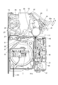
図1は、本発明を適用した実施形態に係るプリンター1の斜視図である。また、図2は、プリンター1の設置状態における断面図である。
プリンター1は、本体10の後方から供給される記録媒体としての感熱ロール紙Sに熱エネルギーを与えて文字、記号或いは画像等を印刷(記録)する記録装置であり、記録後の感熱ロール紙Sを本体10の前面に設けられた排出口11から排出する。
プリンター1は、例えば決済機能を有する自動販売機等の装置(図示略)に内蔵され、領収書、レシート、チケット等の各種帳票を発行する組込型のプリンターである。図2に示すように、プリンター1は、上記装置の筐体を構成する外装パネル101の内側に設置され、プリンター1が排出口11から排出した感熱ロール紙Sが、外装パネル101に形成された排出口102から外部に排出される。
Hereinafter, embodiments of the present invention will be described with reference to the drawings.
FIG. 1 is a perspective view of a
The
The
プリンター1は、上記装置の内部に感熱ロール紙Sとともに固定され、上記装置の制御回路にフレキシブルケーブル103を介して接続されている。プリンター1には、フレキシブルケーブル103を介して、感熱ロール紙Sに印刷する文字や画像のデータやプリンター1の動作を指示するコマンド等の制御情報が入力され、プリンター1の各部を動作させるための電源が供給される。
The
図1に示すように、プリンター1の本体10は、ベースフレーム13、右サイドフレーム15及び左サイドフレーム17からなる本体フレームに各部を設けて構成される。本体10の前面上部には、左右サイドフレーム15、17に対して回動可能に前部フレーム19が取り付けられ、この前部フレーム19の前面を覆うように上部カバー20が配置されている。また、本体10の前面下部にはカッターユニットケース21が設けられ、上部カバー20とカッターユニットケース21との間に上記の排出口11が開口する。
As shown in FIG. 1, the
図2に示すように、本体10の背面には感熱ロール紙Sを取り込む差入口23が開口し、本体10の後部には、差入口23から入った感熱ロール紙Sを斜め下方に案内する下紙案内27及び上紙案内29が設けられ、上紙案内29には用紙センサー25が設けられている。用紙センサー25は、下紙案内27に光を照射して反射光を検出する反射型光センサーであり、用紙センサー25の受光部の検出状態に基づいて下紙案内27上に位置する感熱ロール紙Sの有無を検出できる。
下紙案内27及び上紙案内29の前端は、略水平に配置された記録ヘッド31に臨んでいる。記録ヘッド31は、感熱ロール紙Sの記録面(図2中の下面に相当)に接する複数の発熱素子が直線上に配置されたラインサーマルヘッドであり、ラインサーマルヘッドに駆動電流を供給するヘッドドライバー回路33と一体に構成されている。また、記録ヘッド31に対向してプラテン35が配置され、プラテン35と記録ヘッド31との間に感熱ロール紙Sが挟まれる。
As shown in FIG. 2, an
The front ends of the
プラテン35(搬送ローラー)は、本体10の幅方向に延設され、前部フレーム19に回動自在に支持されたローラープラテンである。プラテン35は、搬送モーター37によって駆動されて回転し、記録ヘッド31との間に感熱ロール紙Sを挟んで搬送する。プラテン35は、搬送モーター37の回転方向により、図中符号Aで示す方向に回る正転動作と、符号Bで示す方向に回る逆転動作とを切り替えて行う。プラテン35が正転動作すると感熱ロール紙Sは排出口11に向けて正送りされ、プラテン35が逆転動作すると感熱ロール紙Sは差入口23側に向けて逆送りされる。
差入口23から本体10に入った感熱ロール紙Sは、下紙案内27と上紙案内29との間を通って記録ヘッド31とプラテン35との間に導かれ、プラテン35の回転力により排出口11に搬送される。この感熱ロール紙Sの搬送路を、図中に符号Pで示す。
The platen 35 (conveying roller) is a roller platen that extends in the width direction of the
The heat-sensitive roll paper S that has entered the
記録ヘッド31及びプラテン35の前方には、感熱ロール紙Sを切断する固定刃41と可動刃43とが配置されている。固定刃41は本体10の前部フレーム19に固定され、可動刃43は前部フレーム19の下方に位置するカッターユニットケース21に内蔵され、固定刃41と可動刃43とは、感熱ロール紙Sの搬送路Pを挟んで上下に対向する。可動刃43は、カッターユニットケース21に内蔵されたカッター駆動モーター45と、搬送モーター37と可動刃43とを連結する駆動機構44によって、上下に駆動され、この可動刃43が上昇して固定刃41とかみ合うことにより感熱ロール紙Sが切断される。この固定刃41、可動刃43、駆動機構44、及び、カッター駆動モーター45によりカッターユニット47が構成される。
A fixed
固定刃41は前部フレーム19に固定され、その前面は安全のため上部カバー20により覆われている。上部カバー20の前端は、排出口11の上方に張り出す前部上紙案内20aとなっている。また、カッターユニットケース21の上部には、水平よりやや上方に伸びる前部下紙案内板49が取り付けられ、これらの前部下紙案内板49及び前部上紙案内20aによって、排出口11を出た感熱ロール紙Sが排出口102に案内される。
記録ヘッド31により印刷された感熱ロール紙Sは、プラテン35により排出口11に搬送され、感熱ロール紙Sの先端が排出口11の前方に位置する排出口102からはみ出した位置で、カッターユニット47により切断される。切断された感熱ロール紙Sは排出口102の外に出て利用者により掴まれて取り出される。
The fixed
The thermal roll paper S printed by the
また、本体10は、記録ヘッド31をプラテン35に向けて付勢する付勢機構55を備えている。略平板状の記録ヘッド31にはヘッド支持板51が下方から接し、付勢機構55は左右のサイドフレーム15、17に固定された板ばねの弾性により、ヘッド支持板51を記録ヘッド31もろとも押し上げて、記録ヘッド31とプラテン35とを密接させる。付勢機構55の付勢力によって記録ヘッド31はプラテン35に押し付けられ、記録ヘッド31とプラテン35とのニップ部には感熱ロール紙Sを挟む押圧力が作用する。この押圧力により、記録ヘッド31と感熱ロール紙Sとが密着して高品位の印刷が可能となり、また、プラテン35と感熱ロール紙Sの滑りが抑制され、正確な搬送が可能になる。
Further, the
ヘッド支持板51の前端には、突起部51aが設けられている。突起部51aは板状のヘッド支持板51の前部を折り曲げて形成された山状の凸部であり、下方から搬送路Pに突出している。突起部51aは、付勢機構55による付勢力が記録ヘッド31とプラテン35に確実に伝わるよう、プラテン35を正しい位置に保持するために設けられている。
A
本体10の前部フレーム19は、左右サイドフレーム15、17に掛け渡された丸棒形状の軸61によって回動自在に支持されており、軸61を中心として前方に開くことができる。図1及び図2に示すように、右サイドフレーム15の前部には前部フレーム19とともに軸61を中心として回動可能に取り付けられた固定レバー63が設けられている。固定レバー63は回動範囲の下端位置で前部フレーム19に係合し、前部フレーム19を右サイドフレーム15に固定する。固定レバー63を跳ね上げるように回動させると、固定レバー63と前部フレーム19の係合が解け、前部フレーム19は前方へ回動可能となる。
The
図3は、前部フレーム19を前方に開いた状態の断面図である。
この図3中に矢印Fで示すように、前部フレーム19を前方に回動させると、前部フレーム19とともにプラテン35及び固定刃41が前方へ移動する。この開放状態ではプラテン35が記録ヘッド31から離れているので、感熱ロール紙Sに対する保持力が無くなり、感熱ロール紙Sの除去、セット、交換等の作業を行うことが可能になる。感熱ロール紙Sの交換等の作業が終了した後は、図3中に矢印Rで示す方向に前部フレーム19が回動され、プラテン35が記録ヘッド31に対向する位置に納まる。
FIG. 3 is a cross-sectional view of the state in which the
As indicated by arrow F in FIG. 3, when the
プリンター1が印刷を行う通常状態では、付勢機構55の付勢力により記録ヘッド31とプラテン35とが押圧されており、前部フレーム19を前方に開くとプラテン35は通常位置から離脱し、記録ヘッド31はヘッド支持板51とともに可動範囲の最上部に移動する。そして、前部フレーム19を前方に開いた状態から通常状態に戻す過程では、プラテン35が付勢機構55の付勢力を受けて収まるように、記録ヘッド31を押し下げる必要が生じる。この過程でプラテン35が直接記録ヘッド31の発熱素子に衝突しないように、プリンター1は、ヘッド支持板51の前部に突起部51aを備えている。突起部51aは記録ヘッド31の前方に位置する山状の突起であり、前側に斜面51bを有しているので、図3の状態からプラテン35を矢印Rで示す方向に移動させると、プラテン35が突起部51aの前側の斜面51bに当接する。この状態から、プラテン35は斜面51bにガイドされながら、さらに矢印R方向に移動すると、付勢機構55の付勢力に抗してヘッド支持板51とともに記録ヘッド31が押し下げられ、プラテン35は突起部51aを乗り越えて、記録ヘッド31と対向する通常位置に復帰する。
In the normal state in which the
このように、本体10は、通常状態ではプラテン35と記録ヘッド31とを付勢力により密着させ、感熱ロール紙Sの交換時には、プラテン35を前方に移動させて記録ヘッド31とプラテン35との密着を解くことが可能な構成とし、この構成において、通常状態に戻す際にプラテン35が記録ヘッド31に衝突しないよう、突起部51aを設けている。
このため、突起部51aが、復帰時のプラテン35に当接するように搬送路Pに向けて突出した形状となることは不可欠であり、プラテン35によって搬送される感熱ロール紙Sは、突起部51aを乗り越えて、排出口11に向かう。つまり、感熱ロール紙Sが搬送される搬送路Pは、突起部51aにおいて上方に屈曲し、この屈曲した搬送路Pを感熱ロール紙Sが搬送される。
また、記録ヘッド31の後方には、記録ヘッド31よりも上部に盛り上がった形状を有するヘッドドライバー回路33が位置しているので、プラテン35は、ヘッドドライバー回路33と突起部51aとによって、通常位置から離脱しないよう保持される。
突起部51aと斜面51bは、ヘッド支持板51に一体的に形成することができるので、場所を取らず、小型化に資することができる。
As described above, the
For this reason, it is indispensable that the protruding
Further, since the
Since the
このように構成されるプリンター1は、プラテン35により搬送された感熱ロール紙Sが排出口11の手前で詰まり(ジャム)を起こした場合に、このジャムを検出するジャム検出センサー39(検出部)を備えている。
ジャム検出センサー39は、図2及び図3に示すように、プラテン35の前方に位置してプラテン35の周面に対向する。ジャム検出センサー39は、反射型の光センサーであり、その検出面39aには発光部(図示略)及び受光部(図示略)が設けられている。このジャム検出センサー39の受光状態に基づいて、ジャム検出センサー39に対向するプラテン35の周面に感熱ロール紙Sがあるか否かを検出できる。
ジャム検出センサー39の位置は、図2に示すように搬送路Pより明らかに上方にある。すなわち、ジャム検出センサー39は、ジャムが発生して、矢印A方向に回転するプラテン35によって搬送路Pより上に感熱ロール紙Sが巻き込まれた場合に、これを検出するためのセンサーである。
The
As shown in FIGS. 2 and 3, the
Position of the
図4は、図2のX−X´線における横断面図である。
この図4はプラテン35を通る断面を下方から見た図であり、図中の上下方向は本体10の幅方向である。
ジャム検出センサー39は、プラテン35の長手方向すなわち本体10の幅方向において、略中央に位置している。プリンター1は、異なる幅サイズの感熱ロール紙S(例えば80mm幅と60mm幅)を使用可能であり、どのサイズを用いるかはプリンター1を収容する装置の用途・目的により決まるが、安定して搬送を行うためには、通常、プラテン35の幅の半分より細い感熱ロール紙Sが用いられることはない。従って、図4に示すように、ジャム検出センサー39をプラテン35の幅方向略中央に設けることで、感熱ロール紙Sのサイズによらず感熱ロール紙Sがジャム検出センサー39から完全に外れた位置を通ることがない。これにより、どのサイズの感熱ロール紙Sが使用されても、ジャムが発生して感熱ロール紙Sがプラテン35に巻き込まれた場合に、これを確実に検出できる。また、同様の理由により、用紙センサー25も、プラテン35の幅方向中央に配置されており、どのサイズの感熱ロール紙Sが使用されても、差入口23から差し入れられた感熱ロール紙Sを確実に検出できる。
4 is a cross-sectional view taken along line XX ′ of FIG.
FIG. 4 is a view of a cross section passing through the
The
また、図2及び図3に示すように、本体10の下部には、プリンター1の制御系を構成する各種回路が実装された制御基板7が収容されている。
以下、この制御基板7に実装されるプリンター1の制御系について説明する。
As shown in FIGS. 2 and 3, a
Hereinafter, a control system of the
図5は、プリンター1の制御系の構成を示すブロック図である。
プリンター1は、プリンター1の各部を制御して印刷動作を実行させる制御部70を有し、この制御部70は、所定のプログラムを実行して各種データを処理するCPU71と、CPU71が実行する基本制御プログラムを記憶したROM73と、CPU71が実行するプログラムや処理対象のデータ等を一時的に記憶するワークエリアを形成するRAM74と、CPU71が実行するプログラムや処理対象のデータ、設定値等を記憶する不揮発性メモリー75とを備えている。
また、プリンター1は、各センサーや入力部から入力されるアナログ信号をデジタル化してCPU71に出力するとともに、CPU71から入力される制御信号に従ってLEDを点灯させるゲートアレイ(G/A)76と、CPU71の制御に従ってモーター等を駆動するモータードライバー77と、CPU71の制御に従って記録ヘッド31を駆動するヘッドドライバー回路33と、を備え、ゲートアレイ76、モータードライバー77及びヘッドドライバー回路33は制御部70のCPU71に接続されている。
FIG. 5 is a block diagram illustrating a configuration of a control system of the
The
In addition, the
また、CPU71には、プリンター1を収容する装置の制御部を構成するホスト基板110と、フレキシブルケーブル103を介して接続されたインターフェース(I/F)72が接続されている。インターフェース72は、フレキシブルケーブル103を接続するためのコネクター等を備え、ホスト基板110とCPU71との間の通信を仲介する。具体的には、インターフェース72は、ホスト基板110から送信される印刷指示のコマンド、印刷データ等を受信してCPU71に出力し、ホスト基板110からステータス要求等のコマンドが送信された場合には、このコマンドを受信してCPU71に出力するとともに、このコマンドに応じてCPU71が出力する応答をホスト基板110に送信する。
The
ゲートアレイ76には、各種スイッチ類を有し、これらスイッチの操作に応じて操作信号を出力する入力部78、1または複数のLEDを備えるLED表示部79、上述した反射型光センサーとして構成される用紙センサー25及びジャム検出センサー39が接続されている。
ゲートアレイ76は、入力部78が出力する操作信号と、用紙センサー25及びジャム検出センサー39が受光量に応じて出力する検出電圧の値とを検出し、これらのアナログ値を量子化してデジタルデータに変換し、CPU71に出力する。CPU71は、ゲートアレイ76から入力されるデータをもとに、入力部78における操作を検出し、また、用紙センサー25及びジャム検出センサー39の検出電圧に基づいて、これらのセンサーによる感熱ロール紙Sの検出状態を判別する。
The
The
モータードライバー77には、搬送モーター37及びカッター駆動モーター45が接続されている。モータードライバー77は、例えばステッピングモーターで構成されるカッター駆動モーター45及び搬送モーター37に対し、駆動電源を供給するとともに必要数の駆動パルスを出力して、可動刃43を移動させて感熱ロール紙Sの切断を行わせ、搬送モーター37を駆動してプラテン35を正転または逆転させる。
A
また、ヘッドドライバー回路33は、上述したように記録ヘッド31と一体に構成され、記録ヘッド31が備える各発熱素子(図示略)に対して個別に駆動電流を供給するとともに電圧を制御し、感熱ロール紙Sへの印刷を行わせる。
In addition, the
CPU71は、用紙センサー25による感熱ロール紙Sの検出状態に基づいて、感熱ロール紙Sの有無を監視しながら、インターフェース72を介してホスト基板110から入力される印刷ジョブを実行し、モータードライバー77を介して搬送モーター37を動作させて感熱ロール紙Sを搬送させながら、ヘッドドライバー回路33により記録ヘッド31を駆動して感熱ロール紙Sへの印刷を実行する。CPU71は、搬送モーター37を動作させて、印刷後の感熱ロール紙Sをカッターユニット47の位置まで搬送させ、モータードライバー77によりカッター駆動モーター45を動作させて感熱ロール紙Sを切断する。また、CPU71は、メンテナンス時等に入力部78のスイッチの操作を検出すると、この操作に応じて、ゲートアレイ76によりLED表示部79の各LEDの点灯状態を変化させる。
The
プリンター1は、プラテン35の回転により感熱ロール紙Sが巻き込まれてジャムが発生した場合に、このジャムを検出してプラテン35を逆転及び正転させてジャムを解消する機能を有する。
図2に示すように、搬送路Pの上方にはプラテン35の周面に対向するようにジャム検出センサー39が配設され、このジャム検出センサー39によって、制御部70は、プラテン35に巻き込まれた感熱ロール紙Sの有無を検出する。このジャムを検出した場合、制御部70は、搬送モーター37を停止させ、さらに搬送モーター37を逆方向に回転させる。これにより搬送モーター37は逆転動作を開始し、プラテン35に巻き込まれた感熱ロール紙Sが搬送路Pに戻される。その後、制御部70は、搬送モーター37を再び正転させ、プラテン35を正転方向に回転させるので、感熱ロール紙Sは再び排出口11に向けて搬送され、ジャムが解消する。
なお、所定回数、搬送モーター37の逆転、正転を1回以上実行し、或いは複数回繰り返してもジャム検出センサー39が引き続き紙を検出している場合は、ジャムが解消できなかったと判断し、LED表示部79の各LEDの点灯状態を変化させ、エラーであることを報知する。これは、図示しないブザーなどの報知音出力手段が出力する音でもよい。この場合、搬送モーター37の逆転、正転を実行する回数は、予め設定され、不揮発性メモリー75に記憶される。
The
As shown in FIG. 2, a
Note that if the
モータードライバー77は、制御部70の制御に従って、搬送モーター37を少なくとも2段階、好ましくは3段階の速度で正方向に回転させる。すなわち、制御部70は、モータードライバー77を制御して、搬送モーター37を、記録ヘッド31により印刷を行わないで感熱ロール紙Sを搬送する場合の通常搬送速度と、記録ヘッド31により印刷中に感熱ロール紙Sを搬送する場合の印刷時搬送速度と、後述する感熱ロール紙Sのジャムを解消する場合のジャム解消時搬送速度とを切り替えて駆動する。これに伴い、プラテン35は、搬送モーター37の通常搬送速度、印刷時搬送速度、及びジャム解消時搬送速度に応じた速度で回転し、感熱ロール紙Sを搬送する。通常搬送速度が最も高速で、次に印刷時搬送速度が高速で、ジャム解消時搬送速度が最も低速である。通常搬送速度は感熱ロール紙Sを搬送するだけでよい場合の搬送速度であり、スループットの高速化のために速いことが好ましい。印刷時搬送速度は、一定水準以上の印刷品質を保つため、記録ヘッド31が感熱ロール紙Sに熱を与えることが可能な速度に抑える必要があるので、通常搬送速度より低速である。また、ジャム解消時搬送速度は、後述するように、感熱ロール紙Sのジャムを解消した後に、ジャムを再発しないように感熱ロール紙Sを搬送するため、特に低い速度となっている。
なお、搬送モーター37を逆転させる場合の搬送速度は、1段階だけでも2段階以上あってもよい。本実施形態では1段階の速度とする。この逆転動作中の搬送速度は、印刷時搬送速度またはジャム解消時搬送速度と同程度またはそれ以下の低速であることが好ましい。感熱ロール紙Sのジャムを解消する場合に、感熱ロール紙Sの損傷等を確実に防ぐことが可能なためである。
The
Note that the conveyance speed when the
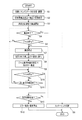
図6は、プリンター1の動作を示すフローチャートである。
この図6に示す動作で、制御部70は、インターフェース72を介してホスト基板110から送信された印刷指示のコマンド、印刷データを受信してRAM74のワークエリアに展開し(ステップS1)、印刷を実行する(ステップS2)。ステップS2で、制御部70は、搬送モーター37を印刷時搬送速度で回転させ、記録ヘッド31により感熱ロール紙Sへの印刷を行う。印刷終了後、制御部70は、搬送モーター37の回転速度すなわちプラテン35の回転速度を通常搬送速度に切り替えて、プラテン35を回転させ、排出口11へ向けて感熱ロール紙Sの搬送を開始する(ステップS3)。
FIG. 6 is a flowchart showing the operation of the
In the operation shown in FIG. 6, the
搬送開始後、制御部70は、感熱ロール紙Sの搬送が終了したか否かを判別し(ステップS4)、搬送が終了する前であれば(ステップS4;No)、ジャム検出センサー39の検出電圧に基づいてジャム検出センサー39が感熱ロール紙Sを検出したか否かを判別する(ステップS5)。
ジャム検出センサー39が感熱ロール紙Sを検出していない場合はステップS4に戻って搬送を継続し、搬送が終了した場合は(ステップS4;Yes)、カッターユニット47によって感熱ロール紙Sを切断し(ステップS6)、本処理を終了する。
After starting the conveyance, the
If the
一方、ジャム検出センサー39が感熱ロール紙Sを検出した場合(ステップS5;Yes)、制御部70は搬送モーター37を停止させ(ステップS7)、予め設定された戻し量だけ感熱ロール紙Sを逆送りするため、搬送モーター37を逆転動作させる(ステップS8)。戻し量は、後述するように、ジャムを解消するに十分な量が予め設定される。設定された戻し量は、搬送モーター37の動作ステップ数や搬送する感熱ロール紙Sの長さ等として、不揮発性メモリー75に記憶されている。
制御部70は、逆送りを行った回数をカウントし、カウント値をRAM74に記憶する機能を有しており、ステップS8で逆送りを行う毎に、カウント値をカウントアップする。
On the other hand, when the
The
続いて、制御部70は、搬送モーター37を正転動作させて、再び感熱ロール紙Sを排出口11に向けて搬送する(ステップS9)。この搬送時、制御部70は、搬送モーター37をジャム解消時搬送速度で回転させ、ステップS8で逆送りした戻し量だけ、感熱ロール紙Sを搬送させる。この搬送中、制御部70は、ジャム検出センサー39の検出状態を監視し(ステップS10)、ジャム検出センサー39が感熱ロール紙Sを検出していない間は(ステップS10;No)、戻し量相当の搬送が終わるまで搬送と監視を継続する(ステップS11)。
Subsequently, the
ジャム検出センサー39が感熱ロール紙Sを検出しないまま戻し量相当の搬送が終わった場合(ステップS11;Yes)、制御部70は、RAM74に記憶している逆送り回数のカウント値をクリアし、ステップS4に戻って、停止していた搬送を継続する。この場合、制御部70は、戻し量相当の搬送が終わった時点で搬送モーター37の回転速度をジャム解消時搬送速度から通常搬送速度に切り替えて、感熱ロール紙Sの所定位置がカッターユニット47の切断位置に達するまで、搬送する。搬送が終了したら(ステップS4;Yes)、制御部70はステップS6に移行して、カッターユニット47によって感熱ロール紙Sを切断し、本処理を終了する。
When conveyance corresponding to the return amount is finished without detecting the thermal roll paper S by the jam detection sensor 39 (step S11; Yes), the
また、戻し量相当の搬送が終わるまでの間にジャム検出センサー39によって感熱ロール紙Sが検出された場合(ステップS10;Yes)、制御部70は、逆送り回数のカウント値が、予め不揮発性メモリー75に記憶している設定回数を超過したか否かを判別する(ステップS12)。ここで、逆送り回数のカウント値が設定回数を超過した場合(ステップS12;Yes)、ステップS7〜S9を繰り返してもジャムが解消していないので、制御部70は、エラーを報知して搬送モーター37を含む各部の動作を停止し(ステップS13)、本処理を終了する。エラーを報知する方法としては、インターフェース72を介してホスト基板110に、エラー発生を示すステータスを通知する方法、LED表示部79を点滅または点灯させる方法、ビープ音等を出力する方法等がある。
また、逆送り回数のカウント値が設定回数を超過していない場合(ステップS12;No)、制御部70はステップS7に戻って、再び逆送りを試行する。
In addition, when the thermal roll paper S is detected by the
If the count value of the number of reverse feeds does not exceed the set number of times (step S12; No), the
図7から図9の各図は、ジャム発生が検出される過程を示す説明図である。
図7には、ジャムが発生する典型的な事例として、排出口102が利用者の指等により塞がれた場合を示す。この場合、プリンター1が感熱ロール紙Sを排出できなくなるが、プラテン35は感熱ロール紙Sを搬送するため矢印A方向に正転するので、感熱ロール紙Sにたるみが生じる。このたるみは、プラテン35と記録ヘッド31とのニップ部Nから排出口11までの間で発生し、特に、搬送路Pが屈曲する突起部51aの位置で発生し易い。これは、突起部51aを乗り越える際に感熱ロール紙Sが折れ曲がり、この曲がりが拡大するようにジャムが生じるためである。
Each of FIGS. 7 to 9 is an explanatory diagram illustrating a process in which occurrence of a jam is detected.
FIG. 7 shows a case where the
突起部51aで感熱ロール紙Sに曲がりが生じた後、さらにプラテン35が矢印A方向に正転すると、ニップ部Nから感熱ロール紙Sが繰り出されることで、感熱ロール紙Sの屈曲部分が大きくなる。その結果、図8に示すように、感熱ロール紙Sの弛み部S1は、回転するプラテン35の周面に接するほど大きくなって、やがてプラテン35の周面に沿って巻き込まれる。
After the
図8に示すように弛み部S1がプラテン35の周面に接するまでの間は、プラテン35がニップ部Nから前方に繰り出した感熱ロール紙Sによって弛み部S1が形成される。
これに対し、弛み部S1がプラテン35に巻き込まれてからは、弛み部S1は折れて二重になって、一方はニップ部Nより上流側の感熱ロール紙Sに繋がり、他方は突起部51aより下流側の感熱ロール紙Sに繋がっている。このため、プラテン35が回転すると、弛み部S1の頂点より上流側の感熱ロール紙Sと下流側の感熱ロール紙Sとの両方がプラテン35に巻き込まれるので、突起部51aより下流側の感熱ロール紙Sは図9中に矢印Zで示す方向に引き込まれる。このように、他の搬送路P上の箇所ではジャムが起こり難いので、感熱ロール紙Sが逃げるところがなく折り畳まれてしまい、プラテン35の逆転によって搬送路Pに戻るので、ジャムの除去を困難にすることがない。
As shown in FIG. 8, the slack portion S <b> 1 is formed by the thermal roll paper S in which the
On the other hand, after the slack portion S1 is caught in the
そして、プラテン35に巻き込まれた弛み部S1がジャム検出センサー39の検出位置SPに達すると、ジャム検出センサー39の検出状態に基づき、制御部70が感熱ロール紙Sのジャムを検出する。制御部70は、プラテン35を停止させ、さらに逆送り動作を行わせることで、弛み部S1の解消を図る。
When the slack portion S1 caught in the
ジャム検出センサー39は、図7〜図9に示すように、ニップ部Nから検出位置SPまでのプラテン35の周面に沿った長さDが、弛み部S1の発生箇所である突起部51aから排出口11の位置Oまでの長さよりも短くなる位置に設置されている。
上述したようにプラテン35に弛み部S1が巻き込まれた後は、突起部51aと排出口11との間にある感熱ロール紙Sが本体10内に引き込まれる。突起部51aより下流側にあった感熱ロール紙Sが先端を含めてプラテン35に巻き込まれてしまうと、プラテン35が逆送りと正転動作をして弛み部S1が解けても、解けた感熱ロール紙Sがうまく突起部51aの下流側に進まない可能性がある。感熱ロール紙Sの先端が搬送路Pから外れてしまうと、その後、プラテン35を逆転し正転しても、感熱ロール紙Sの先端が搬送路Pに沿って排出口11側へ進むことを困難にする。しかし、この実施例では、感熱ロール紙Sの先端が搬送路Pから外れてしまうことがなく搬送路に残った状態となっているので、逆転し正転したとき、感熱ロール紙Sの先端が滑らかに搬送路Pに沿って排出口11側へ進むことができる。
そこで、本実施形態のプリンター1は、ニップ部Nから検出位置SPまでの長さDが、突起部51aから位置Oまでの距離より短くなるようにして、突起部51aの下流側の感熱ロール紙Sが先端を含めてプラテン35に巻き込まれる前に、ジャム検出センサー39が感熱ロール紙Sを検出できる構成としている。この構成により、プラテン35の逆送りと正転によって弛み部S1を解けば、感熱ロール紙Sが確実に排出口11に向けて搬送できる。
As shown in FIGS. 7 to 9, the
As described above, after the slack portion S1 is caught in the
Therefore, in the
また、カッターユニット47によって感熱ロール紙Sを切断した直後は、感熱ロール紙Sの先端はカッターユニット47の切断位置Cにある。このような場合に、弛み部S1を解消してより確実に感熱ロール紙Sを排出口11に搬送するためには、長さDが突起部51aから切断位置Cまでの距離よりも短くなるようにジャム検出センサー39を設けるとよい。この場合、ジャム検出センサー39が弛み部S1を検出した時点で、感熱ロール紙Sの先端が突起部51aより下流側にあるので、カッターユニット47で感熱ロール紙Sを切断した直後であっても、プラテン35の逆送りと正転により弛み部S1を解消して、感熱ロール紙Sを再び排出口11へ搬送できる。
Further, immediately after the thermal roll paper S is cut by the
さらに、ニップ部Nから検出位置SPまでのプラテン35の周面に沿った長さDが、カッターユニット47の切断位置Cから排出口11の位置Oまでの距離より短いと、より好ましい。
例えば図10に仮想線で示すように、ニップ部Nから検出位置SPまでの長さDが長くなる位置にジャム検出センサー39を設置した場合、ジャム検出センサー39が弛み部S1を検出した時点で、突起部51aより下流側にあった感熱ロール紙Sがプラテン35に巻き取られて、感熱ロール紙Sの先端は切断位置Cより上流側に達する。この状態でプラテン35を逆転及び正転させて弛み部S1を解くと、感熱ロール紙Sの先端が固定刃41または可動刃43に引っかかる可能性が否定できない。
この可能性を排除するためには、ジャム検出センサー39が弛み部S1を検出した時点で、感熱ロール紙Sの先端が切断位置Cより下流にあればよい。すなわち、ニップ部Nから検出位置SPまでの長さDは、突起部51aから切断位置Cまでの距離をD1、突起部51aから排出口11の位置Oまでの距離をD2とした場合、D≦D2−D1となる。D2−D1は切断位置Cから排出口11の位置Oまでの距離である。つまり、長さDは、切断位置Cから排出口11の位置Oまでの距離以下が好ましいといえる。
Furthermore, it is more preferable that the length D along the peripheral surface of the
For example, as shown by an imaginary line in FIG. 10, when the
In order to eliminate this possibility, the leading edge of the thermal roll paper S should be downstream from the cutting position C when the
また、ジャム検出センサー39により制御部70がジャム発生を検出してから逆送りを行う「戻し量」は、弛み部S1を解消できるようにするため、少なくともニップ部Nから検出位置SPまでの長さD相当、或いは、長さD以上であることが好ましく、より好ましくは、長さDに、搬送モーター37の動作ステップ数で10ステップ程度を加えた長さとすることである。
戻し量が多いほど確実に弛み部S1を解消できるが、戻し量が大きすぎると逆送り動作の終了時に感熱ロール紙Sの先端がニップ部Nまたは突起部51aよりも上流に言ってしまう。このため、戻し量の上限は、逆送り動作の終了時に感熱ロール紙Sの先端がニップ部Nまたは突起部51aよりも下流に位置する程度である。
Further, the “return amount” in which the
The larger the return amount, the more reliably the slack portion S1 can be eliminated. However, if the return amount is too large, the leading edge of the thermal roll paper S is said to be upstream of the nip portion N or the
以上のように、本発明を適用した実施形態によれば、感熱ロール紙Sを搬送して記録を行い、排出口11から排出するプリンター1において、感熱ロール紙Sを搬送するプラテン35と、プラテン35のニップ部より下流側で突起部51aにより屈曲する屈曲部を有する搬送路Pと、感熱ロール紙Sの搬送路Pから離れて位置し、搬送路Pの屈曲部で搬送路Pから逸脱した感熱ロール紙Sを検出するジャム検出センサー39と、ジャム検出センサー39により感熱ロール紙Sが検出された場合に、プラテン35を逆転させて感熱ロール紙Sを逆送りし、その後に少なくとも逆送りした量だけプラテン35を正転させて感熱ロール紙Sを排出口11へ搬送させる制御部70を備えたこと、を特徴とする。
これにより、屈曲部を有する搬送路Pに感熱ロール紙Sを搬送する間に屈曲部でジャムが発生した場合、ジャム検出センサー39によって搬送路Pから逸脱した感熱ロール紙Sを検出することで速やかにジャムを検出し、プラテン35を逆転させてから再び正転させることで感熱ロール紙Sのジャムを解消する。これにより、感熱ロール紙Sのジャムを速やかに検出して、人手による作業を経ることなくジャムを解消できる。従って、感熱ロール紙Sのジャムによる稼働停止を減らし、プリンター1、及び、プリンター1を内蔵する装置の稼働停止時間の短縮を図ることができ、メンテナンスの作業負担の軽減、メンテナンス費用の軽減、及び、装置の可用性の向上が期待できる。
As described above, according to the embodiment to which the present invention is applied, in the
Thus, when a jam occurs in the bent portion while the thermal roll paper S is conveyed to the conveyance path P having the bent portion, the
また、プリンター1は外装パネル101の内側に配置され、排出口11の外側に位置する外装パネル101の排出口102から感熱ロール紙Sを排出するので、外装パネル101の排出口102において感熱ロール紙Sの搬送が妨げられてジャムが発生した場合に、このジャムを速やかに検出して、プラテン35の逆転および正転の動作によりジャムを解消できる。
さらに、ジャム検出センサー39は、プラテン35の周面に対向する位置において感熱ロール紙Sを検出するよう配置され、プラテン35のニップ部Nからジャム検出センサー39の検出位置までの距離が、突起部51aから排出口11までの距離よりも短いので、突起部51aによる搬送路Pの屈曲部で屈曲してプラテン35に巻き込まれた感熱ロール紙Sを、ジャム検出センサー39によって検出できる。また、突起部51aより下流側に搬送されていた感熱ロール紙Sの全てがプラテン35に巻き込まれてしまう前にジャムを検出できるので、検出後のプラテン35の動作により高率でジャムを解消できる。
さらに、記録ヘッド31に対向配置され、記録ヘッド31との間に感熱ロール紙Sを挟んで搬送するプラテン35の動作によって、人手による作業を経ることなくジャムを解消できる。
Further, since the
Further, the
Further, jamming can be eliminated without manual operation by the operation of the
プリンター1は、プラテン35を記録ヘッド31に対向する通常位置から排出口11側に離脱可能に構成され、プラテン35が離脱位置から通常位置に復帰する過程で、記録ヘッド31にプラテン35が衝突しないように、プラテン35と当接した後滑らかにガイドする斜面51bを備えるもので、搬送路Pに突出する突起部51aを設け、この突起部51aを乗り越えて感熱ロール紙Sを搬送する構成において、突起部51aを乗り越える際に感熱ロール紙Sが曲がってジャムが発生しても、このジャムを速やかに検出して解消できる。また、プラテン35を離脱可能に移動し、感熱ロール紙Sが通る搬送路Pを開放することで、感熱ロール紙Sのセット、および、ジャムが解消しなかった場合の感熱ロール紙Sの除去を容易にすることができる。さらに突起部51aは、プラテン35をガイドする斜面51bと、ジャムを発生させる契機となる屈曲部を、一体で形成することができ、小型化にも有効である。
そして、プリンター1の制御部70は、ジャム検出センサー39により感熱ロール紙Sが検出されてプラテン35を逆転させた後に、通常の記録終了後に感熱ロール紙Sを排出口11へ搬送する通常搬送速度よりも低速のジャム解消時搬送速度で、感熱ロール紙Sを排出口11へ搬送させるので、ジャムの再発を防止し、より確実にジャムを解消することができる。
さらに、ジャム検出センサー39は、プラテン35の幅方向中央に配置されたので、様々な幅の感熱ロール紙Sに対してジャムの発生を速やかに検出できる。
The
Then, the
Furthermore, since the
なお、上記実施形態は本発明を適用した一具体例を示すものであり、本発明はこれに限定されるものではない。例えば、上記実施形態においては、プリンター1が1つのプラテン35により感熱ロール紙Sを搬送する構成を例に挙げて説明したが、本発明はこれに限定されるものではなく、ローラープラテンの他に1または複数の搬送ローラーを設けて感熱ロール紙Sを搬送する構成としてもよい。この場合、感熱ロール紙Sのジャムを検出するジャム検出センサー39は、搬送ローラー及びローラープラテンのうち最も排出口11に近い位置にあるものの周面に対向させて設ければよい。
また、例えば、上記実施形態においては、本体10の外部に保持された感熱ロール紙Sを差入口23から取り込んで印刷を行う構成を例に挙げて説明したが、本発明はこれに限定されるものではなく、本体10の内部に感熱ロール紙を収容する収容部を設けてもよい。
さらに、本発明を適用可能な記録装置は、記録媒体を搬送して記録を行う装置であれば特に制限されず、サーマルラインプリンターに限らず、インクジェット式プリンター、ドットインパクト式プリンター、レーザープリンター、熱昇華型プリンターのいずれであってもよいし、他の方式で文字や画像を形成する装置であってもよく、上記実施形態のような組込型の記録装置に限らず、独立した外装ケースを有するスタンドアロン型の記録装置にも、他の装置の機能を備えた複合機にも本発明を適用可能である。
In addition, the said embodiment shows one specific example to which this invention is applied, and this invention is not limited to this. For example, in the above-described embodiment, the configuration in which the
Further, for example, in the above-described embodiment, the configuration in which the thermal roll paper S held outside the
Furthermore, the recording apparatus to which the present invention can be applied is not particularly limited as long as it is an apparatus that conveys a recording medium and performs recording, and is not limited to a thermal line printer, but is an inkjet printer, a dot impact printer, a laser printer, a thermal printer, and the like. It may be any of sublimation type printers, and may be a device that forms characters and images by other methods, and is not limited to the built-in type recording device as in the above embodiment, and an independent outer case is used. The present invention can be applied to a stand-alone type recording apparatus having an image forming apparatus and a multifunction apparatus having the functions of other apparatuses.
1…プリンター(記録装置)、11…排出口、23…差入口、25…用紙センサー、31…記録ヘッド、35…プラテン(搬送ローラー)、37…搬送モーター、39…ジャム検出センサー(媒体検出部)、39a…検出面、47…カッターユニット、51…ヘッド支持板、51a…突起部(凸部)、55…付勢機構、70…制御部、71…CPU、76…ゲートアレイ、77…モータードライバー、101…外装パネル、102…排出口(出口)、S…感熱ロール紙(記録媒体)。
DESCRIPTION OF
Claims (7)
前記記録媒体を搬送方向に搬送する搬送ローラーと、
前記記録媒体をガイドするもので、前記搬送方向において前記搬送ローラーと前記記録ヘッドのニップ部の下流側で前記記録媒体を屈曲させる屈曲部を有する搬送路と、
前記記録媒体を排出する排出口と、
搬送方向において前記屈曲部の下流側であって前記排出口の上流側に配置され、前記屈曲部の下流側であって前記排出口の上流側の切断位置で前記記録媒体を切断するカッターと、
前記搬送路から離れて位置するもので、前記搬送路の屈曲部から前記搬送ローラーに沿って巻き込まれて、前記搬送路から逸脱した前記記録媒体を検出する媒体検出部と、
前記搬送ローラーを、最も高速の通常搬送速度、次に高速の印刷時搬送速度、及び最も低速の速度の3段階の速度で回転させ、前記媒体検出部により前記記録媒体が検出されない場合は前記搬送ローラーを前記通常搬送速度で回転させ、前記記録ヘッドで記録する場合は前記搬送ローラーを前記印刷時搬送速度で回転させ、前記媒体検出部により前記記録媒体が検出された場合に、前記搬送ローラーを、前記最も低速の速度またはそれ以下の低速で所定量逆転させて前記記録媒体を逆送りし、その後、前記搬送ローラーを前記最も低速の速度で回転させて、少なくとも前記所定量だけ、前記記録媒体を正方向に搬送する制御部と、を備え、
前記搬送ローラーの周面に沿った前記ニップ部から前記媒体検出部の検出位置までの距離が、前記カッターの前記切断位置から前記排出口までの距離よりも短く、前記搬送ローラーに巻き取られた前記記録媒体を、前記記録媒体の先端が前記切断位置より下流にある状態で前記媒体検出部で検出すること、
を特徴とする記録装置。 A recording head for recording on a recording medium;
A transport roller for transporting the recording medium in the transport direction;
A guide for guiding the recording medium, and a conveyance path having a bent portion that bends the recording medium on the downstream side of the nip portion of the recording roller and the recording head in the conveyance direction;
An outlet for discharging the recording medium;
A cutter that is disposed downstream of the bent portion and upstream of the discharge port in the conveying direction, and that cuts the recording medium at a cutting position downstream of the bent portion and upstream of the discharge port;
A medium detection unit that is located away from the conveyance path, is wound along the conveyance roller from a bent portion of the conveyance path, and detects the recording medium deviating from the conveyance path;
When the recording medium is not detected by the medium detection unit, the conveyance roller is rotated at three stages of the highest normal conveyance speed, the next highest printing conveyance speed, and the lowest speed. A roller is rotated at the normal conveyance speed, and when recording is performed by the recording head, the conveyance roller is rotated at the conveyance speed during printing, and when the recording medium is detected by the medium detection unit, the conveyance roller is The recording medium is reversely fed by a predetermined amount at the slowest speed or a lower speed, and then the recording medium is reversely fed, and then the conveying roller is rotated at the slowest speed to at least the predetermined amount. A controller for conveying the
The distance from the nip portion along the circumferential surface of the transport roller to the detection position of the medium detection unit is shorter than the distance from the cutting position of the cutter to the discharge port, and was wound around the transport roller. said recording medium, Rukoto be detected in a state the leading end of the recording medium downstream from the cutting position by the medium detecting unit,
A recording apparatus.
前記搬送ローラーの周面に沿った前記ニップ部から前記媒体検出部の検出位置までの距離が、少なくとも前記搬送路の屈曲部から前記排出口までの距離よりも短いこと、
を特徴とする請求項1に記載の記録装置。 The medium detection unit is arranged to detect the recording medium at a position facing the peripheral surface of the transport roller,
A distance from the nip portion along the circumferential surface of the transport roller to a detection position of the medium detection unit is shorter than at least a distance from a bent portion of the transport path to the discharge port;
The recording apparatus according to claim 1.
を特徴とする請求項1または2のいずれかに記載の記録装置。 The transport roller is a platen that is disposed opposite to the recording head and transports the recording medium with the recording head between the recording head when recording on the recording medium;
The recording apparatus according to claim 1, wherein:
前記前部フレームは、前記本体に対し回動可能に取り付けられるものであり、
前記本体には、少なくとも前記記録ヘッドが搭載され、
前記前部フレームには、少なくとも前記搬送ローラーが搭載されること、
を特徴とする請求項1から3のいずれかに記載の記録装置。 The recording device is composed of a main body and a front frame,
The front frame is rotatably attached to the main body,
At least the recording head is mounted on the main body,
At least the transport roller is mounted on the front frame,
The recording apparatus according to claim 1, wherein the recording apparatus is a recording apparatus.
前記搬送ローラーが前記離脱位置から前記通常位置に移動する際、前記搬送ローラーに当接し通常位置へガイドする斜面を有する突起部が前記記録ヘッド側に設けられ、
前記突起部は、前記搬送路に突出して前記屈曲部を形成し、前記記録媒体は前記突起部を乗り越えて前記排出口側へ搬送されること、
を特徴とする請求項1から4のいずれかに記載の記録装置。 The transport roller is movable between a normal position facing the recording head and a separation position on the discharge port side,
When the transport roller moves from the separation position to the normal position, a protrusion having a slope that contacts the transport roller and guides to the normal position is provided on the recording head side,
The protrusion protrudes into the transport path to form the bent portion, and the recording medium is transported to the discharge port side over the protrusion.
The recording apparatus according to claim 1, wherein:
を特徴とする請求項1から6のいずれかに記載の記録装置。 The predetermined amount is set so that the front end of the recording medium is positioned downstream of the nip portion or the bent portion in the transport direction after the transport roller is reversed by the predetermined amount;
The recording apparatus according to claim 1, wherein:
Priority Applications (4)
| Application Number | Priority Date | Filing Date | Title |
|---|---|---|---|
| JP2010077510A JP5811515B2 (en) | 2010-03-30 | 2010-03-30 | Recording device |
| CN2011100791201A CN102218941B (en) | 2010-03-30 | 2011-03-28 | Recording apparatus and control method of recording apparatus |
| US13/075,151 US8477168B2 (en) | 2010-03-30 | 2011-03-29 | Recording apparatus and control method of recording apparatus |
| RU2011111941/12A RU2481958C2 (en) | 2010-03-30 | 2011-03-29 | Recording device and method of controlling recording device |
Applications Claiming Priority (1)
| Application Number | Priority Date | Filing Date | Title |
|---|---|---|---|
| JP2010077510A JP5811515B2 (en) | 2010-03-30 | 2010-03-30 | Recording device |
Publications (3)
| Publication Number | Publication Date |
|---|---|
| JP2011207074A JP2011207074A (en) | 2011-10-20 |
| JP2011207074A5 JP2011207074A5 (en) | 2013-03-07 |
| JP5811515B2 true JP5811515B2 (en) | 2015-11-11 |
Family
ID=44709194
Family Applications (1)
| Application Number | Title | Priority Date | Filing Date |
|---|---|---|---|
| JP2010077510A Active JP5811515B2 (en) | 2010-03-30 | 2010-03-30 | Recording device |
Country Status (4)
| Country | Link |
|---|---|
| US (1) | US8477168B2 (en) |
| JP (1) | JP5811515B2 (en) |
| CN (1) | CN102218941B (en) |
| RU (1) | RU2481958C2 (en) |
Families Citing this family (17)
| Publication number | Priority date | Publication date | Assignee | Title |
|---|---|---|---|---|
| CN102190197A (en) * | 2010-03-15 | 2011-09-21 | 株式会社东芝 | Recording medium sorting apparatus, erasing apparatus, and recording medium sorting method |
| WO2012066837A1 (en) * | 2010-11-17 | 2012-05-24 | シチズンホールディングス株式会社 | Printer device and paper feeding method for printer device |
| JP5882762B2 (en) * | 2012-01-31 | 2016-03-09 | キヤノン株式会社 | Reading apparatus and recording apparatus |
| US8864278B2 (en) * | 2012-02-24 | 2014-10-21 | Eastman Kodak Company | Detecting potential collision damage to printhead |
| JP2015037982A (en) * | 2012-08-24 | 2015-02-26 | 株式会社Pfu | Manuscript transport device, jam determination method and computer program |
| JP5404873B1 (en) * | 2012-08-24 | 2014-02-05 | 株式会社Pfu | Document feeder, jam determination method, and computer program |
| CN104507693B (en) * | 2012-09-27 | 2018-04-06 | 惠普发展公司,有限责任合伙企业 | Medium blockage clearing |
| JP2014108584A (en) * | 2012-12-03 | 2014-06-12 | Canon Inc | Printing system, printing device, printing device control method, and program |
| JP6201636B2 (en) * | 2013-10-28 | 2017-09-27 | 沖電気工業株式会社 | Media processing device |
| JP6287370B2 (en) * | 2014-03-10 | 2018-03-07 | セイコーエプソン株式会社 | Image recording apparatus and image recording method |
| JP6425449B2 (en) * | 2014-08-05 | 2018-11-21 | サトーホールディングス株式会社 | Thermal printing apparatus and control method thereof |
| JP2017165011A (en) * | 2016-03-17 | 2017-09-21 | セイコーエプソン株式会社 | Recording device and medium feeding method by recording device |
| JP6862228B2 (en) * | 2017-03-10 | 2021-04-21 | キヤノン株式会社 | Sheet feeder and printing equipment |
| US10843491B2 (en) * | 2017-07-07 | 2020-11-24 | Zebra Technologies Corporation | Media unit leveling assembly for media processing devices |
| JP7142896B2 (en) * | 2018-05-21 | 2022-09-28 | 三栄電機株式会社 | Ticket issuing device |
| JP2021154703A (en) * | 2020-03-30 | 2021-10-07 | セイコーエプソン株式会社 | Printer and printer control method |
| KR102604532B1 (en) * | 2023-02-21 | 2023-11-22 | 화성시스템(주) | Device for detecting and removing print paper jams in printer |
Family Cites Families (26)
| Publication number | Priority date | Publication date | Assignee | Title |
|---|---|---|---|---|
| JPH0616294A (en) * | 1991-04-19 | 1994-01-25 | Canon Inc | Recording device |
| JPH05162894A (en) | 1991-12-13 | 1993-06-29 | Tokyo Electric Co Ltd | Paper sheet transport device |
| JPH05238597A (en) | 1992-02-25 | 1993-09-17 | Canon Inc | Recorder |
| JP3212673B2 (en) * | 1992-03-12 | 2001-09-25 | グローリー工業株式会社 | Banknote jam recovery method and recovery device |
| JPH061493A (en) * | 1992-06-19 | 1994-01-11 | Canon Inc | Recording device |
| JPH06980A (en) * | 1992-06-23 | 1994-01-11 | Tokyo Electric Co Ltd | Thermal printer |
| JPH07228387A (en) * | 1994-02-16 | 1995-08-29 | Brother Ind Ltd | Recorder |
| JP3387636B2 (en) | 1994-07-29 | 2003-03-17 | キヤノン株式会社 | Sheet material feeding device and recording device |
| US5867196A (en) | 1994-07-29 | 1999-02-02 | Canon Kabushiki Kaisha | Sheet supply apparatus for controlling sheet feeding with reversing of conveyance direction |
| US5717836A (en) * | 1995-03-09 | 1998-02-10 | Matsushita Electric Industrial Co., Ltd. | Printing apparatus having a retractable curl removal member and reversible roller |
| KR0174230B1 (en) * | 1996-04-18 | 1999-05-15 | 김광호 | Sheets releasing method in case of paper jam |
| KR0184576B1 (en) * | 1996-04-25 | 1999-05-15 | 김광호 | Apparatus and method for removing paper jam of inkjet printer |
| JPH09323454A (en) * | 1996-06-05 | 1997-12-16 | Seiko Epson Corp | Method for confirming loading of paper and thermal printer |
| JPH1148507A (en) * | 1997-07-30 | 1999-02-23 | Seiko Instr Inc | Line thermal printer |
| JP2001253570A (en) * | 2000-03-13 | 2001-09-18 | Canon Inc | Recorder |
| JP3925620B2 (en) * | 2001-11-16 | 2007-06-06 | セイコーエプソン株式会社 | Printer and printer unit |
| JP2004130641A (en) * | 2002-10-09 | 2004-04-30 | Canon Inc | Recording apparatus and recording method |
| JP4251014B2 (en) * | 2003-05-22 | 2009-04-08 | セイコーエプソン株式会社 | Printer and printer control method |
| JP2005186510A (en) * | 2003-12-26 | 2005-07-14 | Seiko Epson Corp | Line type thermal printer and its divide driving method |
| DE602005007527D1 (en) * | 2004-03-26 | 2008-07-31 | Noritsu Koki Co Ltd | printer |
| JP4529732B2 (en) * | 2005-03-01 | 2010-08-25 | ブラザー工業株式会社 | Tape printer |
| JP4827634B2 (en) | 2006-07-06 | 2011-11-30 | キヤノン株式会社 | Conveying apparatus and recording apparatus |
| CN100464987C (en) * | 2006-08-18 | 2009-03-04 | 江苏国光信息产业股份有限公司 | Paper-outputting device for printer and its working method |
| JP2009107287A (en) * | 2007-10-31 | 2009-05-21 | Fujitsu Isotec Ltd | Printing device |
| JP5159370B2 (en) * | 2008-03-03 | 2013-03-06 | キヤノン株式会社 | Image forming apparatus and information processing method |
| JP2010064310A (en) * | 2008-09-09 | 2010-03-25 | Toshiba Tec Corp | Printer |
-
2010
- 2010-03-30 JP JP2010077510A patent/JP5811515B2/en active Active
-
2011
- 2011-03-28 CN CN2011100791201A patent/CN102218941B/en active Active
- 2011-03-29 US US13/075,151 patent/US8477168B2/en active Active
- 2011-03-29 RU RU2011111941/12A patent/RU2481958C2/en active
Also Published As
| Publication number | Publication date |
|---|---|
| JP2011207074A (en) | 2011-10-20 |
| US8477168B2 (en) | 2013-07-02 |
| US20110242257A1 (en) | 2011-10-06 |
| CN102218941A (en) | 2011-10-19 |
| RU2011111941A (en) | 2012-10-10 |
| CN102218941B (en) | 2013-12-04 |
| RU2481958C2 (en) | 2013-05-20 |
Similar Documents
| Publication | Publication Date | Title |
|---|---|---|
| JP5811515B2 (en) | Recording device | |
| JP5482027B2 (en) | Thermal printer | |
| JP3022228B2 (en) | Paper ejection device | |
| JP4964978B2 (en) | Medium detection method, medium detection apparatus, medium discharge apparatus, and printing apparatus | |
| JP2011207074A5 (en) | ||
| JP4946553B2 (en) | Printer, printer control method and control program | |
| JP6264146B2 (en) | Transport device | |
| JP7142896B2 (en) | Ticket issuing device | |
| US11691842B2 (en) | Image forming apparatus | |
| JP2008080649A (en) | Transfer mechanism and recording device with the same | |
| CN115362067A (en) | Printing apparatus | |
| JP2009078524A (en) | Thermal printer | |
| JP5984408B2 (en) | Printer device | |
| JP2009083448A (en) | Printer and issuing apparatus | |
| US11897256B2 (en) | Image forming apparatus | |
| JP2010202305A (en) | Mechanism for guiding recording paper and paper roll printer | |
| JP7349065B2 (en) | Post-processing system and image forming system | |
| JP5414478B2 (en) | Sheet conveying apparatus and recording apparatus | |
| JP2011073184A (en) | Method of controlling conveyance of recording paper of printer, and printer | |
| JP2024001916A (en) | Image recording apparatus | |
| EP2431858A2 (en) | Media processing device, control method for a media processing device, and recording medium storing a program executed by a control unit that controls a media processing device | |
| JP2006225097A (en) | Method for dropping delivered sheet and printer for implementing the method | |
| JP2023163430A (en) | image recording device | |
| JP2005205742A (en) | Printing device and paper feeding switching method therefor | |
| JP2010030189A (en) | Method for detecting faulty arrangement of recording paper and serial printer |
Legal Events
| Date | Code | Title | Description |
|---|---|---|---|
| A521 | Request for written amendment filed |
Free format text: JAPANESE INTERMEDIATE CODE: A523 Effective date: 20130117 |
|
| A621 | Written request for application examination |
Free format text: JAPANESE INTERMEDIATE CODE: A621 Effective date: 20130117 |
|
| A977 | Report on retrieval |
Free format text: JAPANESE INTERMEDIATE CODE: A971007 Effective date: 20131225 |
|
| A131 | Notification of reasons for refusal |
Free format text: JAPANESE INTERMEDIATE CODE: A131 Effective date: 20140107 |
|
| A521 | Request for written amendment filed |
Free format text: JAPANESE INTERMEDIATE CODE: A523 Effective date: 20140307 |
|
| RD02 | Notification of acceptance of power of attorney |
Free format text: JAPANESE INTERMEDIATE CODE: A7422 Effective date: 20140307 |
|
| A131 | Notification of reasons for refusal |
Free format text: JAPANESE INTERMEDIATE CODE: A131 Effective date: 20140617 |
|
| A521 | Request for written amendment filed |
Free format text: JAPANESE INTERMEDIATE CODE: A523 Effective date: 20140808 |
|
| A131 | Notification of reasons for refusal |
Free format text: JAPANESE INTERMEDIATE CODE: A131 Effective date: 20150127 |
|
| A521 | Request for written amendment filed |
Free format text: JAPANESE INTERMEDIATE CODE: A523 Effective date: 20150327 |
|
| TRDD | Decision of grant or rejection written | ||
| A01 | Written decision to grant a patent or to grant a registration (utility model) |
Free format text: JAPANESE INTERMEDIATE CODE: A01 Effective date: 20150825 |
|
| A61 | First payment of annual fees (during grant procedure) |
Free format text: JAPANESE INTERMEDIATE CODE: A61 Effective date: 20150907 |
|
| R150 | Certificate of patent or registration of utility model |
Ref document number: 5811515 Country of ref document: JP Free format text: JAPANESE INTERMEDIATE CODE: R150 |
|
| S531 | Written request for registration of change of domicile |
Free format text: JAPANESE INTERMEDIATE CODE: R313531 |
|
| R350 | Written notification of registration of transfer |
Free format text: JAPANESE INTERMEDIATE CODE: R350 |