JP6201636B2 - Media processing device - Google Patents
Media processing device Download PDFInfo
- Publication number
- JP6201636B2 JP6201636B2 JP2013223430A JP2013223430A JP6201636B2 JP 6201636 B2 JP6201636 B2 JP 6201636B2 JP 2013223430 A JP2013223430 A JP 2013223430A JP 2013223430 A JP2013223430 A JP 2013223430A JP 6201636 B2 JP6201636 B2 JP 6201636B2
- Authority
- JP
- Japan
- Prior art keywords
- card
- medium
- conveyance
- switching unit
- transport
- Prior art date
- Legal status (The legal status is an assumption and is not a legal conclusion. Google has not performed a legal analysis and makes no representation as to the accuracy of the status listed.)
- Active
Links
Images


Description
本発明は、IC書き換え機能およびリライト印字機能などを有する媒体処理装置に関する。 The present invention relates to a medium processing apparatus having an IC rewriting function and a rewrite printing function.
従来の技術において、媒体処理装置には、例えば、ICカードのような媒体のICチップが記憶する情報の書き換えを行うことや、媒体が備えるリライト面の既存の印字内容を消去してから再印字を行うことで、媒体を繰り返して使用するようにしているものがある。(例えば、特許文献1参照)。 In the conventional technology, for example, information stored in an IC chip of a medium such as an IC card is rewritten in the medium processing apparatus, or the existing print content on the rewrite surface included in the medium is erased and reprinted. In some cases, the medium is repeatedly used. (For example, refer to Patent Document 1).
しかしながら、従来の媒体処理装置においては、媒体のICチップが記憶する情報の書き換えや、リライト面への再印字などの処理を終了させ、媒体を媒体挿入排出口へ搬送するときに、ユーザの使用状態などによる媒体の反りのため、また、媒体の表面の汚れが媒体を搬送するローラに付着して滑り、搬送力が低減するため、媒体を円滑に搬送することができないことがあるという問題がある。
本発明は、このような問題を解決することを課題とし、媒体を円滑に搬送できるようにすることを目的とする。
However, in the conventional medium processing apparatus, when the information stored in the IC chip of the medium is rewritten or the process such as reprinting on the rewrite surface is finished and the medium is transported to the medium insertion / ejection port, it is used by the user. There is a problem that the medium may not be smoothly conveyed due to warpage of the medium due to the state or the like, and dirt on the surface of the medium adheres to and slides on the roller that conveys the medium and the conveying force is reduced. is there.
An object of the present invention is to solve such a problem, and an object thereof is to enable a medium to be smoothly conveyed.
そのため、本発明は、カード状媒体を搬送する搬送路を有するカード状媒体処理装置において、前記搬送路の一部に配置され、前記カード状媒体の搬送方向に対して直交する方向に移動し、前記カード状媒体を搬送する搬送切替部と、前記搬送路の前記カード状媒体の詰まりを検知し、前記搬送切替部を制御する制御部とを備え、前記制御部は、前記カード状媒体の詰まりを検知したとき、前記搬送切替部を移動させ、その後、前記搬送切替部を移動させた状態で移動前と同じ搬送方向に、詰まりが検知された前記カード状媒体を搬送することを特徴とする。 Therefore, the present invention moves in the card-shaped medium processing apparatus having a conveying path for conveying a card-like medium, disposed on a portion of the transport path, in a direction perpendicular to the conveying direction of the card media, A conveyance switching unit that conveys the card-like medium; and a control unit that detects clogging of the card-like medium in the conveyance path and controls the conveyance switching unit, and the control unit clogs the card-like medium. when detecting, moving the transport switching unit, then, in the same conveying direction as the previous movement in a state of moving the transport switching unit, characterized by transporting the card-like medium jam is detected .
このようにした本発明は、媒体を円滑に搬送することができるという効果が得られる。 According to the present invention as described above, an effect that the medium can be smoothly conveyed is obtained.
以下、図面を参照して本発明による媒体処理装置の実施例を説明する。 Embodiments of a medium processing apparatus according to the present invention will be described below with reference to the drawings.
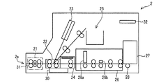
図1は、第1の実施例におけるICカード処理装置の構成を示す概略側面図である。
図1において、媒体処理装置としてのICカード処理装置2は、カード挿入排出口2aと、インサータ部21と、切替部22と、カードリーダ部23と、ICR/W(ICカードRead/Write)部24と、回収部25と、リライト印字部26と、ホッパ部27と、ピッカローラ28と、取忘取込部30と、各部を結びICカード3を搬送する搬送路31と、制御部32とにより構成されている。
FIG. 1 is a schematic side view showing the configuration of the IC card processing apparatus in the first embodiment.
In FIG. 1, an IC
インサータ部21は、図中一点鎖線で囲まれた部分であり、カード挿入排出口2aから挿入されたカードを装置内に引き込むものである。また、インサータ部21は、情報の読取りまたは書込みを行い、また印字が終了したカードをカード挿入排出口2aから排出する。なお、インサータ部21には、カードの磁気ストライプの有無を検知する磁気ヘッドやICカードであるか否かを判別するためのセンサを備えている。
The
搬送切替部としての切替部22は、搬送路31の一部として分岐部に配置され、ICカードの搬送方向に対して直交する回動軸を有しており、回動軸を中心に回動してインサータ部21により引き込んだICカードの搬送先を切り替えて搬送するものであり、ICカードの搬送先をカードリーダ部23、ICR/W部24、回収部25または取忘取込部30へと切り替える。
なお、切替部22は、回動軸を中心に回動してICカードの搬送先を切り替えて搬送するとしたが、それに限られることなく、ICカードの搬送方向に対して直交する方向(図中上下方向)に移動してICカードの搬送先を切り替えて搬送するようにしてもよい。
The
Note that the
カードリーダ部23は、カードの磁気ストライプに記録された情報の読取り、または情報の磁気ストライプへの書き込みを行うものである。このカードリーダ部23には、インサータ部21で磁気ストライプを有するカードであると判別されたカードが搬送される。
ICR/W部24は、ICカードに備えられたICチップに対して情報の読取りまたは書込みを行うものである。このICR/W部24には、インサータ部21で判別されたICカードやホッパ部27から繰り出されたICカードが搬送され、そのICカードのICチップに対して情報の読取りまたは書込みが行われる。
回収部25は、使用済みの旧ICカードを収容するものであり、切替部22で搬送先が切り替えられ、搬送されたICカードを収容するものである。
The
The ICR /
The
リライト印字部26は、印字ヘッド26aおよび消去ヘッド26bを備え、ICカードの表面に形成されたリライト面に印字や印字された文字等の消去を行うものである。このリライト印字部26には、インサータ部21で判別されたICカードやホッパ部27から繰り出されたICカードが搬送され、そのICカードのリライト面に印字し、また印字された文字等を消去する。
ホッパ部27は、ICカード処理装置2に対して着脱可能に構成され、新規のICカードを予め収納しておく収納部である。このホッパ部27は、リライト印字部26の奥部に配設され、底部に形成された開口部から収納したICカードを搬送路31に搬出することができるようになっている。
The
The
ピッカローラ28は、ホッパ部27の底部に形成された開口部を介してホッパ部27に収納されたICカードに接触するように配設され、駆動手段としてのモータからの駆動で回転することにより、ホッパ部27に収容されたICカードを搬送路31へ繰り出すことができるようになっている。
取忘取込部30は、カード挿入排出口2aから排出したカードが所定時間を経過しても受け取られない場合、そのカードを引き込み、収容するものである。
制御部32は、CPU等で構成され、メモリ等の記憶部に記憶された制御プログラム(ソフトウェア)に基づいてICカード処理装置2全体の動作を制御する。
The
The forgetting / taking-in
The
また、制御部32は、切替部22がICカードをインサータ部21などの搬送先へ搬送する際に、搬送路31のICカードの詰まりを検知し、切替部22を制御するものであり、ICカードの詰まりを検知したとき、切替部22を回動させる。
この場合、制御部32は、切替部22を回動させる方向を後述する図4(a)または図5(a)に示すようにICカードの上面方向もしくは下面方向とし、わずかにそれぞれの方向に回動させ、搬送先の搬送路31に対する角度を変更させる。
なお、この制御部32が行う切替部22の回動については後述する。
The
In this case, the
The rotation of the
図2は、第1の実施例におけるICカード書き換え処理の説明図である。
図2に示すように、ICカード処理装置2は、ICカード3がインサータ部21のカード挿入排出口2aから挿入され、インサータ部21でICカード3と判別されると、ICR/W部24でICカード3のICチップから情報の読取りを行う。その後、ICカード3のICチップに対して情報の書き換えを行い、印字が必要な場合はICカード3をリライト印字部26へ搬送し、消去ヘッド26bでICカードのリライト面に印字されている内容を消去し、印字ヘッド26aでICカード3のリライト面に新たな印字内容を印字する。新たな印字内容が印字されたICカード3は、インサータ部21へ搬送されてカード挿入排出口2aから排出される。
FIG. 2 is an explanatory diagram of the IC card rewriting process in the first embodiment.
As shown in FIG. 2, when the
また、ICカード処理装置2は、ICカード3を新規に発行するとき、予めICカード3が収納されたホッパ部27から1枚のICカード3をピッカローラ28により繰り出してICR/W部24へ搬送し、ICR/W部24で情報の書込みを行う。印字が必要な場合はICカード3をリライト印字部26へ搬送し、印字ヘッド26aでICカード3のリライト面に新たな印字内容を印字する。新たな印字内容が印字されたICカード3は、インサータ部21へ搬送されてカード挿入排出口2aから排出される。
Further, when the IC
次に、インサータ部21および切替部22の構成について、図3に基づきながら説明する。
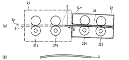
図3は、第1の実施例における第1のリトライ戻し搬送の説明図である。
図3において、インサータ部21および切替部22は、カード挿入排出口2aから挿入された物がICカード3であるか否かを判別する検知センサと、ICカード3を搬送する搬送ローラ対とにより構成されている。インサータ部21には、さらにICカード3の磁気ストライプの有無を検知する磁気ヘッドも備えている。
Next, the configuration of the
FIG. 3 is an explanatory diagram of the first retry return conveyance in the first embodiment.
In FIG. 3, the
インサータ部21は、検知センサ214から図中矢印Bで示す排出方向における下流側へ向かって、検知センサ213、搬送ローラ対216、検知センサ212、磁気ヘッド217および218、搬送ローラ対215、検知センサ211の順に、搬送路31に沿って配置されている。
切替部22は、検知センサ223から図中矢印Bで示す排出方向における下流側へ向かって、搬送ローラ対225、検知センサ222、搬送ローラ対224、検知センサ221の順に、搬送路31に沿って配置されている。
The
The
この切替部22は、ICチップが記憶する情報の書き換え、あるいは、リライト面に再印字するなどの処理を行ったICカード3をカード挿入排出口2aへ排出する際、図中点線で示す位置でICカード3が詰まり、制御部32がジャム(詰まり)監視時間を超えたと判定したとき、制御部32の指示にしたがって第1のリトライ戻し搬送を行い、図中実線で示す位置にICカード3を逆搬送した後、リトライ搬送を行うものである。
なお、ジャム監視時間とは、ICカード3が詰まっているか否かを判断する基準の時間であり、この場合においては検知センサ221がICカード3を検知したときから図示せぬタイマーが計測を開始する。
When the
The jam monitoring time is a reference time for determining whether or not the
また、「搬送ローラ対224がインサータ部21の搬送ローラ対216にICカード3を搬送できない」状態とは、搬送ローラ対224の搬送力が搬送ローラ対216の負荷よりも小さい状態となっている。
この要因としては、例えば、ICカード3が反っているため、搬送ローラ対216がICカード3を挟持できない場合や、ICカード3が汚れているため、搬送ローラ対224が滑り、搬送力が低下した場合などが考えられる。
Further, the state that “the
This may be because, for example, the
上述のような場合、つまり、切替部22がICカード3をインサータ部21へ搬送する際に、搬送路31のICカード3の詰まりを検知したとき、制御部32は、切替部22を回動させる前に、搬送ローラ対216の手前まで搬送した図中点線で示すICカード3を図中矢印Aで示す挿入方向へ戻して逆搬送させ、図中実線で示すようにICカード3が切替部22内の搬送路31に収まるまで搬送し、切替部22にICカード3を戻す(第1のリトライ戻し搬送)。
また、切替部22は回動軸22aを有しており、制御部32の指示にしたがって、モータなどの図示せぬ駆動部により回動するものである。
In the case described above, that is, when the switching
The switching
次に、切替部22が回動することによるリトライ搬送についての説明を図4および図5に基づきながら説明する。
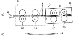
図4は、第1の実施例における1回目のリトライ搬送の説明図である。
図4(a)は切替部22が1回目のリトライ搬送を行っている状態を示しており、図4(b)は図4(a)で示した切替部22の1回目のリトライ搬送で搬送可能なICカード3の形状の例を示している。
Next, a description will be given of retry conveyance based on the rotation of the switching
FIG. 4 is an explanatory diagram of the first retry conveyance in the first embodiment.
FIG. 4A shows a state in which the
図4(a)において、図3に示した第1のリトライ戻し搬送を行ったあと、切替部22は、図中矢印Cで示す媒体上面方向へ回動する。
すると、切替部22内の搬送路31は、インサータ部21内の搬送路31に対して所定の角度となる。
切替部22の搬送ローラ対224は、この状態でICカード3を図中矢印Bで示す排出方向へ搬送する(1回目のリトライ搬送)。
4A, after the first retry return conveyance shown in FIG. 3 is performed, the switching
Then, the
In this state, the pair of
このようにICカード3を搬送することにより、図4(b)に示したように反っているICカード3が搬送ローラ対216に挟持されやすくなるため、ICカード3を円滑に搬送することができる。
また、ICカード3の表面の汚れが搬送ローラ対224に付着して滑り、ICカード3を搬送する搬送力が低減する場合でも、インサータ部21内の搬送路31の上面に押し当てられたICカード3に対する搬送ローラ対224の接触状態が変化することにより、搬送ローラ対224の搬送力の低減を抑制するため、ICカード3を円滑に搬送することができる。
By transporting the
Further, even when dirt on the surface of the
図5は、第1の実施例における2回目のリトライ搬送の説明図である。
図5(a)は切替部22が2回目のリトライ搬送を行っている状態を示しており、図5(b)は図5(a)で示した切替部22の2回目のリトライ搬送で搬送可能なICカード3の形状の例を示している。
図5(a)において、図4(a)に示した1回目のリトライ搬送を行ったあと、切替部22は、図中矢印Dで示す媒体下面方向へ回動する。
すると、切替部22内の搬送路31は、インサータ部21内の搬送路31に対して所定の角度となる。
FIG. 5 is an explanatory diagram of the second retry conveyance in the first embodiment.
FIG. 5A shows a state in which the
5A, after the first retry conveyance shown in FIG. 4A is performed, the switching
Then, the
切替部22の搬送ローラ対224は、この状態でICカード3を図中矢印Bで示す排出方向へ搬送する(2回目のリトライ搬送)。
2回目のリトライ搬送においても、1回目のリトライ搬送と同様に、図5(b)に示したように反っているICカード3が搬送ローラ対216に挟持されやすくなるため、また、ICカード3を搬送する搬送力が低減する場合でも、インサータ部21内の搬送路31の下面に押し当てられたICカード3に対する搬送ローラ対224の接触状態が変化することにより、搬送ローラ対224の搬送力の低減を抑制するため、ICカード3を円滑に搬送することができる。
In this state, the pair of
In the second retry conveyance, the
上述した構成の作用について説明する。
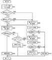
リトライ搬送処理を図6の第1の実施例におけるリトライ搬送処理の流れを表すフローチャートの図中Sで示すステップにしたがって図3から図5までを参照しながら説明する。
S101:制御部32は、切替部22からインサータ部21にICカード3が搬送されず、検知センサ221がICカード3を検知してからジャム監視時間を超えたと判定し、ICカード3のジャムを検出する。
S102:制御部32は、切替部22に第1のリトライ戻し搬送を行うように指示する。
The operation of the above configuration will be described.
The retry conveyance process will be described with reference to FIGS. 3 to 5 in accordance with the step indicated by S in the flowchart showing the flow of the retry conveyance process in the first embodiment of FIG.
S101: The
S102: The
S103:制御部32は、切替部22に1回目のリトライ搬送を行うように指示する。
S104:制御部32は、各検知センサにより正常排出されたか否かを判定し、正常排出されていないと判定すると処理をS105へ移行し、正常排出されたと判定すると処理をS109へ移行する。
S105:制御部32は、切替部22に再度、第1のリトライ戻し搬送を行うように指示する。
S106:制御部32は、切替部22に2回目のリトライ搬送を行うように指示する。
S103: The
S104: The
S105: The
S106: The
S107:制御部32は、各検知センサにより正常排出されたか否かを判定し、正常排出されていないと判定すると処理をS108へ移行し、正常排出されたと判定すると処理をS109へ移行する。
S108:制御部32は、排出リトライオーバーエラーとして係員にICカード3のジャムを警告灯などで報告し、本処理を終了する。
S109:制御部32は、インサータ部21にカード挿入排出口2aにICカード3を排出させ、ユーザがICカード3を受け取るのを待ち、本処理を終了する。
S107: The
S108: The
S109: The
以上説明したように、第1の実施例では、ICカードのジャムを検出した制御部が、切替部にICカードを戻して搬送させた後、搬送先の搬送路に対して所定の角度に切替部の搬送路を回動させるようにしたことにより、ICカードの反りに対応するとともに、切替部の搬送ローラの汚れによる搬送力の低減を抑制するようにしたため、媒体を円滑に搬送することができるという効果が得られる。
なお、第1の実施例では、ICカードを切替部からインサータ部に搬送し、カード挿入排出口へ排出する場合を例として説明したが、それに限られることなく、挿入されたICカードを切替部からICR/W部などに搬送する場合に適用することも可能であり、また、挿入されたICカードをインサータ部などから切替部に搬送する場合に適用することも可能である。
As described above, in the first embodiment, the control unit that detects the jam of the IC card returns the IC card to the switching unit and transports it, and then switches to a predetermined angle with respect to the transport path of the transport destination. By rotating the conveyance path of the unit, it is possible to cope with the warp of the IC card and to suppress the reduction of the conveyance force due to the contamination of the conveyance roller of the switching unit, so that the medium can be conveyed smoothly. The effect that it can be obtained.
In the first embodiment, the case where the IC card is transported from the switching unit to the inserter unit and discharged to the card insertion / extraction port is described as an example. The present invention can also be applied to the case where the inserted IC card is transported from the inserter section or the like to the switching section.
本実施例におけるインサータ部21は、第2のリトライ戻し搬送を行い、ICカード3が反っている場合やICカード3の表面の汚れが搬送ローラ対216に付着して滑り、ICカード3を搬送する搬送力が低減する場合においても、第1の実施例の第1のリトライ戻し搬送を行うことなく、ICカード3をカード挿入排出口2aへ搬送できるようにするものである。
The
図7は、第2の実施例における第2のリトライ戻し搬送の説明図である。
なお、インサータ部21および切替部22の構成は上述した第1の実施例と同様であるため、同一の符号を付してその説明を省略する。
図7において、インサータ部21は、ICチップが記憶する情報の書き換え、あるいは、リライト面に再印字するなどの処理を行ったICカード3をカード挿入排出口2aへ排出する際、図中点線で示す位置でICカード3が詰まり、制御部32がジャム監視時間を超えたと判定したとき、第2のリトライ戻し搬送を行うものである。
FIG. 7 is an explanatory diagram of second retry return conveyance in the second embodiment.
In addition, since the structure of the
In FIG. 7, when the
この場合においては、検知センサ212がICカード3を検知したときから図示せぬタイマーが計測を開始し、制御部32がジャム監視時間を超えたか否かを判定する。
また、図中点線で示す位置でICカード3が詰まる要因としては、例えば、搬送ローラ対216に搬送する際に搬送ローラ対224がICカード3の汚れなどで滑ることにより時間が掛かったため、搬送ローラ対216がICカード3を搬送し始めたところでジャム監視時間を超えてしまったことなどが考えられる。
In this case, a timer (not shown) starts measuring from when the
In addition, as a factor that the
上述のような場合、つまり、切替部22がICカード3を搬送先へ搬送する際に、搬送路31のICカード3の詰まりを検知したときであって、搬送先がICカード3を受け取っているときに、制御部32は、インサータ部21に、磁気ヘッド217および218の手前まで搬送した図中点線で示すICカード3を挟持して受け取った状態を維持しながら、図中矢印Aで示す挿入方向へ逆搬送させて戻す(第2のリトライ戻し搬送)。
このようにICカード3を搬送することにより、第1の実施例の第1のリトライ戻し搬送を行って切替部22までICカード3を戻し、再度搬送ローラ対216に挟持させることなく、搬送ローラ対216がICカード3を挟持した状態から搬送を行い、再度ジャム監視時間を超える確率は少なくなるため、ICカード3を円滑に搬送することができる。
In the case described above, that is, when the switching
By carrying the
上述した構成の作用について説明する。
リトライ搬送処理を図8の第2の実施例におけるリトライ搬送処理の流れを表すフローチャートの図中Sで示すステップにしたがって図7を参照しながら説明する。
切替部22が行うリトライ処理を図6の第1の実施例におけるリトライ搬送処理の流れを表すフローチャートの図中Sで示すステップにしたがって図6および図7を参照しながら説明する。
S201:図6におけるS101と同様の処理であるため説明を省略する。
The operation of the above configuration will be described.
The retry conveyance process will be described with reference to FIG. 7 in accordance with the step indicated by S in the flowchart showing the flow of the retry conveyance process in the second embodiment of FIG.
The retry process performed by the switching
S201: Since it is the same process as S101 in FIG. 6, description is abbreviate | omitted.
S202:制御部32は、搬出ローラ対216の排出方向における上流側に配置されている検知センサ213がICカード3を検知しているか否かを判定し、検知している(検知センサON)と判定すると処理をS203へ移行し、検知していない(検知センサOFF)と判定すると処理をS209へ移行する。
S203:制御部32は、搬出ローラ対216の排出方向における下流側に配置されている検知センサ212がICカード3を検知しているか否かを判定し、検知している(検知センサON)と判定すると処理をS204へ移行し、検知していない(検知センサOFF)と判定すると処理をS209へ移行する。
S202: The
S203: The
S204:制御部32は、搬送ローラ対216に第2のリトライ戻し搬送を行うように指示する。
S205:制御部32は、各検知センサによりICカード3が正常排出されたか否かを判定し、正常排出されていないと判定すると処理をS207へ移行し、正常排出されたと判定すると処理をS206へ移行する。
S206:正常排出されたと判定した制御部32は、インサータ部21にカード挿入排出口2aへICカード3を排出するように指示し、ユーザがICカード3を受け取るのを待ち、本処理を終了する。
S204: The
S205: The
S206: The
S207:制御部32は、ジャム監視時間を超えたか否かを判定し、ジャム監視時間を超えたと判定するとリトライオーバーとして処理をS208へ移行し、ジャム監視時間を超えていないと判定すると処理をS204へ移行する。
S208:制御部32は、排出リトライオーバーエラーとして係員にICカード3のジャムを警告灯などで報告し、本処理を終了する。
S209〜S216:図6におけるS102〜S109と同様の処理であるため説明を省略する。
S207: The
S208: The
S209 to S216: The processing is the same as S102 to S109 in FIG.
以上説明したように、第2の実施例では、インサータ部の搬送ローラ対がICカードを挟持した状態から再度搬送を行うことにより、ジャム監視時間を超える確率は少なくなるため、媒体を円滑に搬送することができるという効果が得られる。
なお、第2の実施例では、インサータ部の搬送ローラ対を例として説明したが、それに限られることなく、リライト印字部の搬送ローラ対などに適用することも可能である。
As described above, in the second embodiment, since the pair of transport rollers of the inserter transports again from the state where the IC card is sandwiched, the probability of exceeding the jam monitoring time is reduced, so that the medium is transported smoothly. The effect that it can do is acquired.
In the second embodiment, the conveyance roller pair of the inserter unit is described as an example. However, the present invention is not limited to this, and the present invention can be applied to the conveyance roller pair of the rewrite printing unit.
2 ICカード処理装置
2a カード挿入排出口
3 ICカード
21 インサータ部
22 切替部
22a 回動軸
23 カードリーダ部
24 ICR/W部
25 回収部
26 リライト印字部
27 ホッパ部
28 ピッカローラ
30 取忘取込部
31 搬送路
211〜214、221〜223 検知センサ
215、216、224、225 搬送ローラ対
217、218 磁気ヘッド
2 IC
Claims (9)
前記搬送路の一部に配置され、前記カード状媒体の搬送方向に対して直交する方向に移動し、前記カード状媒体を搬送する搬送切替部と、
前記搬送路の前記カード状媒体の詰まりを検知し、前記搬送切替部を制御する制御部とを備え、
前記制御部は、前記カード状媒体の詰まりを検知したとき、前記搬送切替部を移動させ、その後、前記搬送切替部を移動させた状態で移動前と同じ搬送方向に、詰まりが検知された前記カード状媒体を搬送することを特徴とするカード状媒体処理装置。 In the card- like medium processing apparatus having a conveyance path for conveying the card-like medium ,
Said disposed on a portion of the transport path, the transport switching unit which moves in a direction perpendicular to the conveying direction of the card media to transport the card media,
A controller that detects clogging of the card-like medium in the conveyance path and controls the conveyance switching unit ;
Wherein the control unit, upon detecting a blockage of the card-like medium, moving the conveyance path switching unit, then, in the same conveying direction as the previous movement in a state of moving the transport switching unit, clogging is detected A card- like medium processing apparatus for conveying a card-like medium.
前記搬送切替部は、前記搬送路の分岐部に配置されることを特徴とするカード状媒体処理装置。 The card-like medium processing apparatus according to claim 1,
The card-type medium processing apparatus, wherein the transport switching unit is arranged at a branching portion of the transport path.
前記搬送切替部は、前記カード状媒体の搬送方向に対して直交する回動軸を有し、前記回動軸を中心に回動して搬送先を切り替えることを特徴とするカード状媒体処理装置。 The card-like medium processing device according to claim 2,
The card-type medium processing apparatus, wherein the conveyance switching unit has a rotation axis that is orthogonal to a conveyance direction of the card-like medium, and rotates about the rotation axis to switch a conveyance destination. .
前記制御部は、前記搬送切替部が前記カード状媒体を前記搬送先へ搬送する際に、または、搬送元が前記カード状媒体を前記搬送切替部へ搬送する際に、前記搬送路の前記カード状媒体の詰まりを検知したとき、前記搬送切替部を回動させることを特徴とするカード状媒体処理装置。 In the card-like medium processing device according to claim 3,
The control unit is configured such that when the transport switching unit transports the card-like medium to the transport destination, or when a transport source transports the card-like medium to the transport switching unit , the card in the transport path when detecting clogging of Jo media, card-shaped medium processing apparatus characterized by rotating the transport switching unit.
前記制御部は、前記搬送切替部を回動させる方向を前記カード状媒体の上面方向もしくは下面方向とし、前記搬送先の前記搬送路に対する角度、または、前記搬送切替部の前記搬送路に対する角度を変更させ、
前記搬送路における前記カード状媒体の詰まりを検知したとき、前記搬送切替部を上面方向もしくは下面方向のいずれか一方向に回動させてリトライ搬送を行い、このリトライ搬送で前記カード状媒体が正常に搬送されない場合に、前記搬送切替部を前記一方向の反対方向に回動させて、さらにリトライ搬送を行うことを特徴とするカード状媒体処理装置。 The card-like medium processing device according to claim 4,
The control unit sets the rotation direction of the conveyance switching unit as an upper surface direction or a lower surface direction of the card-like medium, and determines an angle of the conveyance destination with respect to the conveyance path or an angle of the conveyance switching unit with respect to the conveyance path. is changed,
When the clogging of the card-like medium in the conveyance path is detected, the conveyance switching unit is rotated in one direction of the upper surface direction or the lower surface direction to carry out retry conveyance, and the card-like medium is normal by this retry conveyance. The card-like medium processing apparatus further performs retry conveyance by rotating the conveyance switching unit in a direction opposite to the one direction when the medium is not conveyed .
前記制御部は、前記搬送切替部が前記カード状媒体を前記搬送先へ搬送する際に、前記搬送路の前記カード状媒体の詰まりを検知したとき、前記搬送切替部を回動させる前に、前記カード状媒体を逆搬送させ、前記搬送切替部に前記カード状媒体を戻すことを特徴とするカード状媒体処理装置。 In the card-like medium processing device according to claim 4 or 5,
When the conveyance switching unit detects the clogging of the card-like medium in the conveyance path when the conveyance switching unit conveys the card-like medium to the conveyance destination, before rotating the conveyance switching unit , wherein by reversely conveying the card media, the card-like medium treatment apparatus characterized by returning the card-like medium to the conveying switch portion.
前記制御部は、前記搬送切替部が前記カード状媒体を前記搬送先へ搬送する際に、前記搬送路の前記カード状媒体の詰まりを検知したときであって、前記搬送先が前記カード状媒体を受け取っているときに、前記カード状媒体を受け取った状態を維持しながら前記搬送先内で逆搬送させたあと、前記カード状媒体を搬送させることを特徴とするカード状媒体処理装置。 In the card-like medium processing device according to claim 4 or 5,
The control unit detects a clogging of the card-like medium in the conveyance path when the conveyance switching unit conveys the card-like medium to the conveyance destination, and the conveyance destination is the card-like medium. A card-like medium processing apparatus, wherein the card-like medium is conveyed after being reversely conveyed in the conveyance destination while maintaining the state where the card-like medium is received.
前記制御部は、前記搬送元が前記カード状媒体を前記搬送切替部へ搬送する際に、前記搬送路の前記カード状媒体の詰まりを検知したとき、前記搬送切替部を回動させる前に、前記カード状媒体を逆搬送させ、前記搬送元に前記カード状媒体を戻すことを特徴とするカード状媒体処理装置。 In the card-like medium processing device according to claim 4 or 5,
The control unit detects the clogging of the card-like medium in the conveyance path when the conveyance source conveys the card-like medium to the conveyance switching unit, and before rotating the conveyance switching unit , wherein by reversely conveying the card media, card-shaped medium processing device characterized by returning the card-like medium to the transfer origin.
前記制御部は、前記搬送元が前記カード状媒体を前記搬送切替部へ搬送する際に、前記搬送路の前記カード状媒体の詰まりを検知したときであって、前記搬送切替部が前記カード状媒体を受け取っているときに、前記カード状媒体を受け取った状態を維持しながら前記搬送先内で逆搬送させたあと、前記カード状媒体を搬送させることを特徴とするカード状媒体処理装置。 In the card-like medium processing device according to claim 4 or 5,
Wherein, when said conveying source transports the card media into the transport switching unit, there is when it detects clogging of the card-like medium of the conveying path, the conveying switch portion shape the card An apparatus for processing a card-like medium, wherein when the medium is received, the card-like medium is conveyed after being reversely conveyed in the conveyance destination while maintaining the state of receiving the card-like medium.
Priority Applications (1)
| Application Number | Priority Date | Filing Date | Title |
|---|---|---|---|
| JP2013223430A JP6201636B2 (en) | 2013-10-28 | 2013-10-28 | Media processing device |
Applications Claiming Priority (1)
| Application Number | Priority Date | Filing Date | Title |
|---|---|---|---|
| JP2013223430A JP6201636B2 (en) | 2013-10-28 | 2013-10-28 | Media processing device |
Publications (2)
| Publication Number | Publication Date |
|---|---|
| JP2015087812A JP2015087812A (en) | 2015-05-07 |
| JP6201636B2 true JP6201636B2 (en) | 2017-09-27 |
Family
ID=53050580
Family Applications (1)
| Application Number | Title | Priority Date | Filing Date |
|---|---|---|---|
| JP2013223430A Active JP6201636B2 (en) | 2013-10-28 | 2013-10-28 | Media processing device |
Country Status (1)
| Country | Link |
|---|---|
| JP (1) | JP6201636B2 (en) |
Family Cites Families (5)
| Publication number | Priority date | Publication date | Assignee | Title |
|---|---|---|---|---|
| JPS597324Y2 (en) * | 1979-09-29 | 1984-03-06 | 株式会社リコー | collation device |
| JP3217530B2 (en) * | 1993-03-25 | 2001-10-09 | 株式会社東芝 | Paper transport device |
| JPH09320009A (en) * | 1996-05-27 | 1997-12-12 | Fujitsu Ltd | Medium processing device |
| JP4225934B2 (en) * | 2004-02-24 | 2009-02-18 | 沖電気工業株式会社 | Card processing device |
| JP5811515B2 (en) * | 2010-03-30 | 2015-11-11 | セイコーエプソン株式会社 | Recording device |
-
2013
- 2013-10-28 JP JP2013223430A patent/JP6201636B2/en active Active
Also Published As
| Publication number | Publication date |
|---|---|
| JP2015087812A (en) | 2015-05-07 |
Similar Documents
| Publication | Publication Date | Title |
|---|---|---|
| JP5899748B2 (en) | Medium processing apparatus and method for controlling medium processing apparatus | |
| JP6201636B2 (en) | Media processing device | |
| JP6324232B2 (en) | Page turning device | |
| JP5948803B2 (en) | Media processing device | |
| JP6426077B2 (en) | ATM and ATM automatic cleaning method | |
| JP2010079606A (en) | Card processing apparatus | |
| JP5899750B2 (en) | Medium processing apparatus, method for controlling medium processing apparatus, and program | |
| JP6467335B2 (en) | Automatic transaction apparatus, ink transfer prevention method and ink transfer prevention program in automatic transaction apparatus | |
| JP2000076390A (en) | Card issuing machine | |
| JP7190868B2 (en) | CARD PROCESSING DEVICE, TOLL COLLECTION MACHINE, CARD PROCESSING METHOD, PROGRAM | |
| JP5847422B2 (en) | Booklet processing device | |
| JP4931468B2 (en) | Media processing device | |
| JP4081393B2 (en) | Image sensor operation confirmation method, operation confirmation apparatus, and operation confirmation program | |
| JP2010066940A (en) | Automatic transaction apparatus and method of controlling the same | |
| JP2008165471A (en) | Device for handling card | |
| JP2023137284A (en) | Card issuance device and card issuing method | |
| JP4718306B2 (en) | Rewrite card processor | |
| JP2001147993A (en) | Device and method for issuing ic card | |
| JP2022086060A (en) | Card reader and card discharge control method | |
| JP3913007B2 (en) | Automatic passbook issuing device | |
| JP5866926B2 (en) | RECORDING DEVICE, RECORDING DEVICE CONTROL METHOD, AND PROGRAM | |
| JP2008070960A (en) | Reader/writer, reader/writer control method, and printing method | |
| JP2017004384A (en) | IC card processing device | |
| JP2007004351A (en) | Card issue device | |
| JPH11167609A (en) | Card issuing mechanism in card vending machine |
Legal Events
| Date | Code | Title | Description |
|---|---|---|---|
| A621 | Written request for application examination |
Free format text: JAPANESE INTERMEDIATE CODE: A621 Effective date: 20160816 |
|
| A977 | Report on retrieval |
Free format text: JAPANESE INTERMEDIATE CODE: A971007 Effective date: 20170220 |
|
| A131 | Notification of reasons for refusal |
Free format text: JAPANESE INTERMEDIATE CODE: A131 Effective date: 20170228 |
|
| A521 | Written amendment |
Free format text: JAPANESE INTERMEDIATE CODE: A523 Effective date: 20170405 |
|
| A131 | Notification of reasons for refusal |
Free format text: JAPANESE INTERMEDIATE CODE: A131 Effective date: 20170516 |
|
| A521 | Written amendment |
Free format text: JAPANESE INTERMEDIATE CODE: A523 Effective date: 20170704 |
|
| TRDD | Decision of grant or rejection written | ||
| A01 | Written decision to grant a patent or to grant a registration (utility model) |
Free format text: JAPANESE INTERMEDIATE CODE: A01 Effective date: 20170801 |
|
| A61 | First payment of annual fees (during grant procedure) |
Free format text: JAPANESE INTERMEDIATE CODE: A61 Effective date: 20170814 |
|
| R150 | Certificate of patent or registration of utility model |
Ref document number: 6201636 Country of ref document: JP Free format text: JAPANESE INTERMEDIATE CODE: R150 |