JP5809561B2 - Hydraulic valve circuit - Google Patents
Hydraulic valve circuit Download PDFInfo
- Publication number
- JP5809561B2 JP5809561B2 JP2011531047A JP2011531047A JP5809561B2 JP 5809561 B2 JP5809561 B2 JP 5809561B2 JP 2011531047 A JP2011531047 A JP 2011531047A JP 2011531047 A JP2011531047 A JP 2011531047A JP 5809561 B2 JP5809561 B2 JP 5809561B2
- Authority
- JP
- Japan
- Prior art keywords
- load
- fluid
- mast
- lift
- valve
- Prior art date
- Legal status (The legal status is an assumption and is not a legal conclusion. Google has not performed a legal analysis and makes no representation as to the accuracy of the status listed.)
- Active
Links
Images

Classifications
-
- G—PHYSICS
- G01—MEASURING; TESTING
- G01G—WEIGHING
- G01G19/00—Weighing apparatus or methods adapted for special purposes not provided for in the preceding groups
- G01G19/08—Weighing apparatus or methods adapted for special purposes not provided for in the preceding groups for incorporation in vehicles
- G01G19/10—Weighing apparatus or methods adapted for special purposes not provided for in the preceding groups for incorporation in vehicles having fluid weight-sensitive devices
-
- B—PERFORMING OPERATIONS; TRANSPORTING
- B66—HOISTING; LIFTING; HAULING
- B66F—HOISTING, LIFTING, HAULING OR PUSHING, NOT OTHERWISE PROVIDED FOR, e.g. DEVICES WHICH APPLY A LIFTING OR PUSHING FORCE DIRECTLY TO THE SURFACE OF A LOAD
- B66F9/00—Devices for lifting or lowering bulky or heavy goods for loading or unloading purposes
- B66F9/06—Devices for lifting or lowering bulky or heavy goods for loading or unloading purposes movable, with their loads, on wheels or the like, e.g. fork-lift trucks
- B66F9/075—Constructional features or details
- B66F9/12—Platforms; Forks; Other load supporting or gripping members
- B66F9/18—Load gripping or retaining means
- B66F9/183—Coplanar side clamps
-
- B—PERFORMING OPERATIONS; TRANSPORTING
- B66—HOISTING; LIFTING; HAULING
- B66F—HOISTING, LIFTING, HAULING OR PUSHING, NOT OTHERWISE PROVIDED FOR, e.g. DEVICES WHICH APPLY A LIFTING OR PUSHING FORCE DIRECTLY TO THE SURFACE OF A LOAD
- B66F9/00—Devices for lifting or lowering bulky or heavy goods for loading or unloading purposes
- B66F9/06—Devices for lifting or lowering bulky or heavy goods for loading or unloading purposes movable, with their loads, on wheels or the like, e.g. fork-lift trucks
- B66F9/075—Constructional features or details
- B66F9/12—Platforms; Forks; Other load supporting or gripping members
- B66F9/18—Load gripping or retaining means
- B66F9/184—Roll clamps
-
- B—PERFORMING OPERATIONS; TRANSPORTING
- B66—HOISTING; LIFTING; HAULING
- B66F—HOISTING, LIFTING, HAULING OR PUSHING, NOT OTHERWISE PROVIDED FOR, e.g. DEVICES WHICH APPLY A LIFTING OR PUSHING FORCE DIRECTLY TO THE SURFACE OF A LOAD
- B66F9/00—Devices for lifting or lowering bulky or heavy goods for loading or unloading purposes
- B66F9/06—Devices for lifting or lowering bulky or heavy goods for loading or unloading purposes movable, with their loads, on wheels or the like, e.g. fork-lift trucks
- B66F9/075—Constructional features or details
- B66F9/20—Means for actuating or controlling masts, platforms, or forks
- B66F9/22—Hydraulic devices or systems
-
- F—MECHANICAL ENGINEERING; LIGHTING; HEATING; WEAPONS; BLASTING
- F15—FLUID-PRESSURE ACTUATORS; HYDRAULICS OR PNEUMATICS IN GENERAL
- F15B—SYSTEMS ACTING BY MEANS OF FLUIDS IN GENERAL; FLUID-PRESSURE ACTUATORS, e.g. SERVOMOTORS; DETAILS OF FLUID-PRESSURE SYSTEMS, NOT OTHERWISE PROVIDED FOR
- F15B2211/00—Circuits for servomotor systems
- F15B2211/30—Directional control
- F15B2211/305—Directional control characterised by the type of valves
- F15B2211/3056—Assemblies of multiple valves
- F15B2211/3059—Assemblies of multiple valves having multiple valves for multiple output members
- F15B2211/30595—Assemblies of multiple valves having multiple valves for multiple output members with additional valves between the groups of valves for multiple output members
-
- F—MECHANICAL ENGINEERING; LIGHTING; HEATING; WEAPONS; BLASTING
- F15—FLUID-PRESSURE ACTUATORS; HYDRAULICS OR PNEUMATICS IN GENERAL
- F15B—SYSTEMS ACTING BY MEANS OF FLUIDS IN GENERAL; FLUID-PRESSURE ACTUATORS, e.g. SERVOMOTORS; DETAILS OF FLUID-PRESSURE SYSTEMS, NOT OTHERWISE PROVIDED FOR
- F15B2211/00—Circuits for servomotor systems
- F15B2211/50—Pressure control
- F15B2211/55—Pressure control for limiting a pressure up to a maximum pressure, e.g. by using a pressure relief valve
-
- F—MECHANICAL ENGINEERING; LIGHTING; HEATING; WEAPONS; BLASTING
- F15—FLUID-PRESSURE ACTUATORS; HYDRAULICS OR PNEUMATICS IN GENERAL
- F15B—SYSTEMS ACTING BY MEANS OF FLUIDS IN GENERAL; FLUID-PRESSURE ACTUATORS, e.g. SERVOMOTORS; DETAILS OF FLUID-PRESSURE SYSTEMS, NOT OTHERWISE PROVIDED FOR
- F15B2211/00—Circuits for servomotor systems
- F15B2211/50—Pressure control
- F15B2211/555—Pressure control for assuring a minimum pressure, e.g. by using a back pressure valve
-
- F—MECHANICAL ENGINEERING; LIGHTING; HEATING; WEAPONS; BLASTING
- F15—FLUID-PRESSURE ACTUATORS; HYDRAULICS OR PNEUMATICS IN GENERAL
- F15B—SYSTEMS ACTING BY MEANS OF FLUIDS IN GENERAL; FLUID-PRESSURE ACTUATORS, e.g. SERVOMOTORS; DETAILS OF FLUID-PRESSURE SYSTEMS, NOT OTHERWISE PROVIDED FOR
- F15B2211/00—Circuits for servomotor systems
- F15B2211/50—Pressure control
- F15B2211/565—Control of a downstream pressure
Description
本発明は、資材運搬機器に用いる油圧弁回路に関するものであり、より詳細には、フリーリフトマストを有する資材運搬機器に関連するクランプ部材の重量応答制御に適している油圧弁回路に関するものである。 The present invention relates to a hydraulic valve circuit used in a material transporting device, and more particularly to a hydraulic valve circuit suitable for weight response control of a clamp member related to a material transporting device having a free lift mast. .
標準的なフォークリフトや他のタイプの資材運搬機器は、典型的には、積荷をある高さから別の高さにホイスト、即ちリフトするためのマストアセンブリを有しており、このようなマストアセンブリは、概して、特定のタイプの積荷を扱うために設計された種々のアタッチメントを受け入れることができるように構成されている。例えば、カートンクランプまたはペーパーロールクランプのような積荷クランプのアタッチメントを用いることができ、これらは、それぞれ、積荷の側部に充分な把持力を与えて積荷をある場所から別の場所までリフトして運ぶための油圧制御可能な積荷クランプ部材を有する。 Standard forklifts and other types of material handling equipment typically have a mast assembly for hoisting, i.e., lifting loads from one height to another. Are generally configured to accept various attachments designed to handle a particular type of load. For example, load clamp attachments such as carton clamps or paper roll clamps can be used, each of which lifts the load from one place to another with sufficient grip on the sides of the load. It has a hydraulically controllable load clamping member for carrying.
マストアセンブリは、概して、2つの汎用タイプのうちの1つ、すなわち「フリーリフト」または「非フリーリフト」のいずれかのタイプである。フリーリフトマストは、マストアセンブリの全高が対応して変化することなく、「フリーリフト」の全可動域にわたって積荷をある高さから別の高さまでリフトすることができる。フリーリフトの可動域を超えて積荷をリフトするには、マストをテレスコープし、リフトする範囲を伸長する必要がある。マストは、次々に順次テレスコープするいくつかの段を有するようにできる。各段は、一般的に、伸長可能な1つ以上の油圧シリンダを有し、これらのシリンダは駆動されると、完全に伸長してから、次の段に関連する伸長可能な1つ以上の油圧シリンダが駆動される。連続する各々の段の油圧シリンダは、通常、駆動するために、前の段のシリンダよりも高いホイスト圧力を必要とする。したがって、例えばフリーリフトのリフト可動域およびメインリフトのリフト可動域を有するフリーリフトマストでは、1つまたは複数のメインリフトシリンダは、1つまたは複数のフリーリフトシリンダが完全に伸長した位置に達するまでは伸長し始めない。 A mast assembly is generally of one of two general purpose types, either “free lift” or “non-free lift”. A free lift mast can lift a load from one height to another over the entire range of motion of the “free lift” without correspondingly changing the overall height of the mast assembly. To lift a load beyond the range of free lift, it is necessary to telescope the mast and extend the lift range. The mast can have several stages that telescope one after the other. Each stage typically has one or more extendable hydraulic cylinders that, when driven, fully extend and then have one or more extendable cylinders associated with the next stage. The hydraulic cylinder is driven. Each successive stage hydraulic cylinder typically requires a higher hoist pressure than the previous stage cylinder to drive. Thus, for example, in a free lift mast having a lift range of free lift and a lift range of main lift, one or more main lift cylinders until one or more free lift cylinders reach a fully extended position. Does not begin to stretch.
これとは対照的に、非フリーリフトマストは、積荷がリフトされると即座にテレスコープし始める。このようにマストがテレスコープするのは、頭上が制限された環境では望ましくない。例えば、囲いのあるトラクタトレーラは、内部の高さが例えば104インチに制限されることがある。特定のリフトトラックにおいて、マストを縮めた高さが、カウンターバランス型の着座式リフトトラックに見られるように、79〜84インチである場合、マストをさらにテレスコープさせてもトレーラの天井に支障をきたさないようにするために、マストをテレスコープするのに利用できる垂直空間はわずか20〜25インチに過ぎないことがある。 In contrast, non-free lift masts begin to telescope as soon as the load is lifted. This telescoping of the mast is undesirable in an overhead environment. For example, an enclosed tractor trailer may have an internal height limited to, for example, 104 inches. In certain lift trucks, if the height of the mast is 79-84 inches, as seen in counterbalanced seated lift trucks, the trailer ceiling can be disturbed even if the mast is further telescoped. To avoid mess, the vertical space available to telescope the mast may be only 20-25 inches.
フリーリフトマストは、一般的に、マストをフリーリフトの可動域を超えて伸長するために、ホイストラインの圧力を段階的または漸次高くする必要があるため、主に油圧制御のシステムにおいて、積荷の重量を検知するためにホイストラインの圧力を利用し、このような圧力に応答して把持力を自動的にそれ相応に調整するように構成されるものは、このようなマストを用いて実現することはできなかった。このような把持力調整用に電子制御装置を使用する代替設計のものには、単位コストが高価になったりシステムの複雑さが増したりするとともに、マストの伸長に応じて可動にしなければならない電気導体が必要になるという不都合がある。したがって、フリーリフトマストを有する資材運搬システムに関連する、積荷クランプ部材の力を重量に応じて自動制御する、種々の油圧弁回路が必要とされている。 Freelift masts generally require a stepwise or progressive increase in hoist line pressure to extend the mast beyond the freelift range of motion, so in mainly hydraulic control systems, What is constructed using such a mast is configured to utilize the pressure of the hoist line to detect weight and automatically adjust the gripping force accordingly in response to such pressure. I couldn't. Such an alternative design that uses an electronic control device for adjusting the gripping force increases the unit cost and increases the complexity of the system, as well as the electricity that must be made movable as the mast expands. There is a disadvantage that a conductor is required. Accordingly, there is a need for various hydraulic valve circuits that automatically control the load clamp member force as a function of weight associated with a material handling system having a free lift mast.
本発明をより完全に理解するために、図面は、本発明の種々の実施形態による例示的な油圧回路を示している。しかしながら、図面は、本発明の範囲を制限するものではない。 For a more complete understanding of the present invention, the drawings illustrate exemplary hydraulic circuits according to various embodiments of the present invention. However, the drawings are not intended to limit the scope of the invention.
以下の詳細な説明では、種々の実施形態を充分に理解するために、多数の特定細部を説明する。しかしながら、当業者は、これらの特定細部がなくとも本発明を実施することができ、本発明は記載された実施形態に限定されるものではなく、本発明は種々の代替実施形態で実施することもできることを理解するであろう。したがって、他の例において、周知の方法、手順、構成要素、およびシステムについての詳細な説明は省略する。 In the following detailed description, numerous specific details are set forth in order to provide a thorough understanding of various embodiments. However, one of ordinary skill in the art may practice the invention without these specific details, and the invention is not limited to the described embodiments, and the invention may be practiced in various alternative embodiments. You will understand that you can also. Accordingly, in other examples, detailed descriptions of well-known methods, procedures, components, and systems are omitted.
図1は、積荷リフトシステムであって、フリーリフトマストと、このようなシステムにおける積荷クランプ部材の重量応答制御に適している種々の油圧弁回路とを有する積荷リフトシステム100の例示回路図である。図示のように、システム100は、一般に、積荷クランプ部材(図示せず)同士の間に保持される積荷に把持力を与えるために揃って動作し得る、1つ以上の流体動力アクチュエータ101,103を備えている。図1に概略的に示す、少なくとも1つの細長で縦方向に伸長可能な流体動力リフト装置は、フリーリフト段154およびメインリフト段156を有している。手動操作式の積荷クランプセレクタ弁134および積荷リフトセレクタ弁146と、これらのセレクタ弁134,146の手動操作に応え、流体動力アクチュエータ101,103およびリフト装置154,156の動作を制御する種々の油圧弁回路と、が設けられている。
FIG. 1 is an exemplary circuit diagram of a
積荷クランプ部材は、その少なくとも1つが流体動力アクチュエータ101,103の1つ以上によって制御可能であり、ペーパーロールクランプのアームまたは少なくとも1つの流体動力アクチュエータによって制御可能な任意のタイプの積荷クランプ部材とすることができる。例えば、積荷クランプ部材は、カートンクランプのアタッチメントにおけるクランプアームとすることができる。しかしながら、説明のために、積荷リフトシステム100を、タンデム動作するように配置され各々が流体動力アクチュエータ101,103の1つによって制御される一対の積荷クランプ部材を有するペーパーロールクランプのアタッチメントとの関連で説明する。タンデム配置では、流体動力アクチュエータ101,103は、流体ライン(即ち油圧流体の導管)118,120を経て油圧流体が流体動力アクチュエータ(即ちシリンダ)101,103のヘッド側に導入されるにつれて、また同時に、流体動力アクチュエータ(即ちシリンダ)101,103のロッド側から流体ライン(即ち油圧流体の導管)122,124を経て油圧流体が排出されるにつれて、積荷クランプ部材を閉じるように構成される。
The load clamp member can be any type of load clamp member, at least one of which can be controlled by one or more of the fluid powered
各々の流体動力アクチュエータ101,103は、積荷クランプ部材を開閉するための油圧回路を備える積荷クランプ弁アセンブリ126によって制御されるようにすることができる。積荷クランプ弁アセンブリ126に用いられる特定の回路は、少なくとも1つの積荷クランプ閉じライン(即ち油圧流体の導管)130および少なくとも1つの積荷クランプ開きライン132に応答して積荷クランプ部材を選択的に開閉する、動力アクチュエータ101,103の少なくとも1つを動作させる従来型の回路を備えるようにできる。例えば、積荷クランプ弁アセンブリ126は、ペーパーロールクランプのアタッチメントのクランプ部材を制御するためのパイロット操作式のチェック弁、および関連回路を備えるようにすることができる。他の例として、積荷クランプ弁アセンブリ126は、カートンクランプのアタッチメントのクランプ部材を制御するためのパイロット操作式のチェック弁と、流体分配器/結合器と、を備えるようにすることができる。
Each fluid powered
図1に概略的に示すように、リフトシステム100は、フリーリフト段154および少なくとも1つのメインリフト段156を有する少なくとも1つの細長で縦方向に伸長可能な流体動力リフト装置(154,156)を備えている。リフト装置154,156は、フリーリフトの可動域(図1において154として概略的に示す)および少なくとも1つのメインリフトの可動域(図1において156として概略的に示す)を有する、単一で多段式の流体動力装置とすることもできる。しかしながら、リフト装置154,156は、マストを展開させずに積荷クランプ部材をリフトするためのフリーリフトの縦方向可動域と、リフト装置が伸長するにつれてマストが展開する少なくとも1つのメインリフトの縦方向可動域とを有するように構成した、流体動力装置のアセンブリを備えることができる。図に概略的に示すように、フリーリフト段154のピストンはメインリフト段156のピストンよりも大きな圧力面積を有しているので、フリーリフト段154は、メインリフト段156よりも、ライン158における伸長作動用の流圧が低くて済む。したがって、ライン158への油圧流体を増量することにより、フリーリフト段154は、その最終移動端まで伸長し、その後ライン158への流体を増量すると、メインリフト段156が伸長し始める。
As schematically shown in FIG. 1, the
図1の油圧弁回路は、3つの異なるモジュール、すなわち弁アセンブリ128、150および152にグループ化したものを示しているが、種々のコンポーネントは異なるグループ化をすることもできるし、異なる数のモジュールまたは弁アセンブリにグループ化することもできる。例えば、150および152の回路は、単一のモジュールまたは弁アセンブリとすることができる。さらに、図1の回路は、部分的に、独立して用いることも、また代替回路とともに用いることもできる。例えば、150および152の回路は、128に示す回路とは異なる回路と共に用いることができる。
Although the hydraulic valve circuit of FIG. 1 shows three different modules, grouped into
図示のように、弁アセンブリ128にグループ化された油圧弁回路は、リフト装置154,156に関連する油圧回路から検知された積荷重量に相当する圧力をライン168で受けて、その検知された積荷重量に相当する圧力を積荷クランプ部材の重量応答制御に用いるための回路を備えている。弁アセンブリ150および152にグループ化された油圧弁回路は、ライン168にて受け取られる、積荷の検知重量に相当する圧力が均等化されて当該重量がリフト装置154,156の縦方向に伸長可能な位置にほぼ無関係となるようにする回路であって、積荷クランプセレクタ弁134および積荷リフトセレクタ弁146を閉じた際にリフト装置154,156を備える1つまたは複数のシリンダを蓄圧器として機能させ、これにより積荷リフトシステム100の積荷クランプ部材を常時自動重量応答制御するための回路を含む。
As shown, the hydraulic valve circuit grouped into
弁アセンブリ128に示す油圧弁回路は、積荷クランプセレクタ弁134から油圧流体を受け取るための積荷クランプ閉じ回路を含んでいる。例えば、ペーパーロールを取り扱う積荷リフトシステム100が装備されたリフトトラックの操縦者は、積荷クランプセレクタ弁134を動かして、ポンプ142から油圧流体を積荷クランプ閉じライン136に流して、パイロット操作式弁190を脱座させ、まずは流体導管186に、次に流体導管130を経て積荷クランプ弁アセンブリ126まで油圧流体を流し続けることにより、積荷クランプ部材の閉じ作用を開始することができる。積荷クランプ閉じライン130に油圧流体が導入されるにつれて、同時に油圧流体は積荷クランプ開きライン132を経て排出される。バネでバイアスされ通常は開いている二方弁196は、積荷クランプ開きライン132を経て排出される流体を貯留槽(またはタンク)140に戻すための経路を提供する。積荷クランプセレクタ弁134を、積荷クランプ開きライン138の流体圧力を増大させる位置にすると、二方弁196は、図示のように、積荷クランプ開きライン138からパイロットされて、弁が閉じられて流体が流れない位置に動かされる。システム100に過度の圧力が生じた場合、容器140に流体を戻すために、安全逃し弁144が設けられている。
The hydraulic valve circuit shown in the
積荷クランプ部材が、積荷の側部に把持力をかけて、その積荷をしっかり掴む際には、積荷クランプ閉じライン136の油圧圧力が、調節可能な圧力逃し弁194または他の適切な弁によって所望閾値の(即ち開始の)把持圧力まで増大する。例えば、圧力逃し弁194は、積荷クランプ閉じライン136の流体圧力を650psiに制限するように設定して、この制限を超える積荷クランプセレクタ弁134からの油圧流体は、クランプされる積荷にかかる把持圧力を増やし続けるのではなくて、リフトトラックの貯留槽140に戻されるようにすることができる。
When the load clamp member applies a gripping force to the side of the load and firmly grips the load, the hydraulic pressure in the load
積荷クランプ閉じライン136における流体圧力が、圧力逃し弁194の設定値、即ち閾値圧力にまで増大するにつれて、パイロット操作式のチェック弁190の直ぐ下流の箇所184にて検知される流体圧力184もまた、閾値圧力にまで増大する。パイロットライン174は、2つのパイロット操作式で調整可能のバネバイアスされた2位置弁172,176の位置を制御するために184の箇所にて検知された圧力を受け取り、これらの2位置弁は、リフト装置154,156に関連するライン168および油圧回路から受け入れられる流体圧力の範囲を選択的に制御するのに用いられる。弁172は、低めの圧力限界値を設定するのに用いて、当該限界値を下回ると積荷クランプ閉じ回路が油圧的に積荷リフト回路から切り離されるようにするのが好適であり、また弁176は、最大クランプ圧力を設定するのに用いて、当該圧力を超えると積荷クランプ閉じ回路が油圧的に積荷リフト回路から切り離されるようにするのが好適である。2位置弁176は通常開いている弁として示してあり、ライン174によって閉じられるかまたは流体の流れがない状態にパイロットされない限り流体が流れるようにしてある一方、2位置弁172は通常は閉じている弁として示してあり、ライン174によって開かれるかまたは流体の流れがある状態にパイロットされない限り流体の流れを遮るようにしてある。2位置弁172,176の各々は、バネでバイアスされるようにして、パイロットラインの圧力がバネ抵抗の設定値を超えるまでは通常の状態に留まるようにする。積荷クランプ開きライン132およびバネの上のライン170の圧力により、弁172,176はそれらの通常の状態に戻る。積荷クランプ開きライン132,138における圧力も、パイロットライン192を経てチェック弁190を脱座させ、積荷クランプ閉じ回路から流体を排出する。
As the fluid pressure in the load
弁172に対するバネ抵抗は、圧力逃し弁194の閾値すなわち開始圧力の設定値より低くしつつも、積荷クランプ部材が積荷を把持するために閉じる際に、これらの積荷クランプ部材が、下方にドリフトするのを防ぐ程度に高く設定するのが好適である。典型的なバネ抵抗の設定値は、弁172のバネに対しては600psi、また弁176のバネに対しては1800psiとすることができる。184の箇所にて検知される流体圧力が、一旦弁172のバネ設定値すなわち例えば600psiに達すると、弁172は開いて、流体圧力が、現在開いている弁172の下流と、通常開いている弁176の下流と、またチェック弁178の下流とにおいても検出されるようになる。弁172および176の双方が開くと、ライン168からの流体圧力によって、積荷の重量が、180の箇所にて検知できるようになる。弁172が開くまで、積荷クランプ閉じ回路における圧力は、ホイストライン148および168の圧力から分離される。2位置弁176および172の双方がともに開いている時だけ、ライン168からの流体は、180の箇所にて積荷クランプ閉じ回路に受け入れられる。チェック弁178は、積荷クランプ閉じ回路からの流体がライン168を経て積荷リフト回路へ流れるのを防止する。
While the spring resistance to the
チェック弁182は、ライン168からの流体が積荷クランプ閉じ回路の上流に流れるのを阻止し、その代わりにライン168からの流体を、圧力調整弁188を経て強制的に流す。圧力調整弁188は、ライン168を経て受け取られる重量に比例する流体圧力との関連で、積荷クランプ部材によって与えられるクランプ圧力を調整するのに用いることができる。例えば、比較的容量が大きめの流体動力アクチュエータ101,103を有するリフトシステムでは、ライン168から受け取られる重量に比例する油圧圧力によって、積荷に与えられる把持力が過剰になることがある。このような場合、圧力調整弁188を用いて、積荷を把持するのに利用できる可能な最大圧力を減らすことができる。あるタイプの積荷の脆弱性および安定性といったような他のファクタや、リフト装置154,156を備えた1つまたは複数の積荷リフトシリンダのサイズおよび容量や、後に詳しく述べるような、リフト装置154,156に関連する均圧回路150の圧力増大効果によっては、ライン168から受け取られるクランプ圧力を減らすことが必要になることもある。
弁188の位置には、ライン168における圧力に可変的に応答し、1つ以上のパイロット制御式の逃し弁または減圧弁を含む、任意の好適なタイプの圧力調整弁を用いることができる。
Any suitable type of pressure regulating valve can be used for the position of
積荷リフトの動作の間、積荷をクランプする閾値圧力に達したら、積荷クランプセレクタ弁134をその中央の非作動位置に戻し、そしてホイストすなわち積荷リフトセレクタ弁146を動かして、ポンプ142からホイスト作動ライン148に油圧流体が流れるようにし、リフト装置154,156を伸長させて積荷を持ち上げる。流体導管148,158、および168が単に共に相互連結される場合、ライン168にて検知される積荷重量とライン168内の油圧圧力との関係は、リフト装置154,156の位置に応じて変動する。これは、フリーリフト154にて積荷をリフトするのに必要な油圧圧力は、メインリフト156にて同じ積荷をリフトするよりも低い油圧圧力で済むためである。例えば、メインリフト段156が作動するためには、400psiの追加の油圧圧力が必要になる。したがって、このようなリフトシステムから入手可能な積荷重量信号は、リフト装置がフリーリフトであるかメインリフトであるかによって変化する。
When a threshold pressure is reached that clamps the load during load lift operation, the load
弁アセンブリ150および152にグループ化された油圧弁回路は、ライン168にて受け取られて検知される積荷重量を均等化して、リフト装置154,156の縦方向に伸長可能な位置にほぼ無関係となるようにする回路を含んでいる。図示のように、例示の弁アセンブリ150は、フリーリフトシリンダ154とメインリフトシリンダ156との間の作動圧力の差を補償する圧力差調整弁164を有している。例えば、圧力調整弁164は、メインリフトシリンダ156の比較的小さな面積のピストンを動作させるのにライン158にて必要とされる下流の高い圧力に比べて、ライン158における圧力を400psi低減させて、フリーリフトシリンダ154を動作させるように調整することができる。フリーリフトシリンダ154の動作中、ライン148における圧力は弁164によって効果的に増大されて、ライン168において検出される積荷重量を、メインリフトシリンダ156の動作中に当然発生する積荷重量に等しくする。
The hydraulic valve circuits grouped into
フリーリフト154の動作中は、積荷がマストをテレスコープせずにリフトされるため、メインリフト段156は動かないままである。一実施例において、弁アセンブリ152は、プランジャにより作動される通常は閉じている二方弁160を備え、マストの可動なメインリフトのテレスコープする区域の横材198の下で、マストの最も低い(固定された)区域の横材に取り付けられる。フリーリフト段154がその最終の上側移動端に達した後には、メインリフト段156が作動して、メインリフトの横材198がプランジャ162から上方へ動くことにより、ライン168における圧力が二方弁160を開く位置に動かす。これにより、流体が均圧弁164をバイパスするようになり、その減圧効果は除去される。積荷をリフトし続けるためにライン148を経て追加の油圧流体が導入されると、その流体は均圧弁164をバイパスするため、ライン148において、リフト装置154,156のうちメインリフト段156を作動させるための高い圧力が得られる。他のタイプの弁またはコンポーネントを用いて、リフト装置154,156がそのメインリフト156の可動域にある時に、均圧弁164をバイパスするようにもできる。
During operation of the
リフト装置154,156をそのメインリフト156の可動域から引っ込める時には、油圧流体を、二方弁(またはバイパス弁)160を経て流すことができる。二方弁160が一旦閉じると(メインリフトの横材198がプランジャ162を押し下げると)、流体はチェック弁166を経て流れることにより均圧弁164をバイパスすることができ、チェック弁166は、リフト装置154,156が更に引っ込められる際に、油圧流体をフリーリフト段154から排出する経路を提供する。
When the
チェック弁166は、積荷クランプセレクタ弁134および積荷リフトセレクタ弁146を閉じた際に、リフト装置154,156を備える1つまたは複数のシリンダを蓄圧器として機能させることにより、積荷リフトシステム100に積荷クランプ部材の常時自動重量応答動力制御を与えることができる。例えば、検知される積荷重量の大きさが増大する場合、チェック弁166によって、リフト装置154,156からの流体が、積荷クランプセレクタ弁134または積荷リフトセレクタ弁146のいずれかを同時に作動させなくても、ライン168を経て積荷クランプ閉じ回路への流体を自動的に増やすことができる。同様に、積荷にかかる把持力が低下する場合には、チェック弁166によって、リフト装置154,156からの流体が、積荷クランプセレクタ弁134または積荷リフトセレクタ弁146のいずれかを同時に作動させなくても、積荷クランプ閉じ回路への流体を自動的に増やすことができる。
When the load
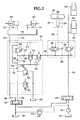
ここまで、プランジャ作動式の二方弁160を備えた弁アセンブリ152について説明したが、図2に示すように、弁アセンブリ152は、例えば、マストの伸長可能な位置に応答するスイッチ204であって、弁アセンブリ150におけるソレノイド作動式の通常は開いている二方弁200に電線206を経て作動信号を供給するスイッチ204を備えることができる。図2において、ソレノイド作動式の二方弁200は、図1にならって、作動されて閉じた位置にあるのを示している。なお、図1は、リフト装置154,156がフリーリフト154の可動域にて動作するための、二方弁160が閉じた(閉鎖)位置にある様子を示している。一実施例において、マストの可動なメインリフトの区域の横材198に、例えばターゲット202のような、スイッチトリガ要素または他のデバイスを取り付け、そしてマストの下方または固定部分に、スイッチ204(例えば近接スイッチ)を取り付けることができる。一実施例において、近接スイッチ204は、リフト装置154,156のうちの、フリーリフト154の可動域の全伸長範囲にわたって、ソレノイド作動式の二方弁200を、作動されて閉じた位置に維持する作動信号を供給する。フリーリフト段154がその上側の最終移動端に達した後、メインリフトの横材198がマストの固定された部分から上方へ動くことにより、スイッチ素子は分離されて、ソレノイド作動式の二方弁200の作動状態が解除されるようになり、これにより二方弁200は開いた位置に動く。これにより、流体は均圧弁164をバイパスするようになり、その減圧効果は除去される。積荷をリフトし続けるためにライン148を経て追加の油圧流体が導入されると、その流体は均圧弁164をバイパスするため、ライン148において、リフト装置154,156のうちメインリフト段156を作動させるための高い圧力が得られる。スイッチ204およびソレノイド弁200が電気的なものであっても、それらを双方とも、マストまたはリフトトラックにおいて固定されてマストの伸長に応じて動かない部分に取り付けることにより、マストの伸長に応じて動かなければならないため危険性および耐久性の問題に曝される導電体を設ける必要はなくなる。他のタイプの弁またはコンポーネントを用いて、リフト装置154,156がそのメインリフト156の可動域にある時に、均圧弁164をバイパスするようにもできる。
Up to now, a
リフト装置154,156をそのメインリフト156の可動域から引っ込める時には、油圧流体を、二方弁(またはバイパス弁)200を経て流すことかできる。二方弁200が一旦閉じると、流体はチェック弁166を経て流れることにより均圧弁164をバイパスすることができ、チェック弁166は、リフト装置154,156が更に引っ込められる際に、油圧流体をフリーリフト段154から排出する経路を提供する。
When the
2段式(すなわちフリーリフトおよびメインリフト)のリフト装置について説明してきたが、均圧弁およびバイパス弁を追加して、ライン168にて検知される積荷重量がリフト装置の縦方向に伸長可能な位置に無関係となるように、必要とされる高い作動圧力を補償することにより、追加のメインリフト段を用いることもできる。例えば、リフト装置が、図1に示した単一のメインリフト段156の先に第2のメインリフト段を含む場合、均圧弁164と直列に他の均圧弁を加えることができ、また、第1のメインリフト段156がその最終移動端に達した時に追加の(第2の)メインリフト段を作動させるために、追加された均圧弁をバイパスする他の弁を加えることもできる。
The lift device of the two-stage type (that is, the free lift and the main lift) has been described, but the position where the product load detected by the
本明細書において使用した用語および表現は、説明のためのものであり、本発明を限定するものではない。このような用語および表現を用いることにより、明細書中で示し説明した特徴の全部または一部と均等なものを除外するものではない。本発明の技術的範囲は、特許請求の範囲における請求項によってのみ規定され限定される。 The terms and expressions used in the present specification are illustrative and do not limit the present invention. The use of such terms and expressions does not exclude equivalents to all or part of the features shown and described in the specification. The technical scope of the present invention is defined and limited only by the claims in the claims.
Claims (3)
前記マストは流体動力リフトアクチュエータに動作可能に係合し、
前記流体動力リフトアクチュエータの流体圧力は、前記重量の大きさに可変的に依存するとともに前記マストの縦方向に伸長可能な異なる位置にも可変的に依存し、
前記油圧弁回路は、前記流体動力リフトアクチュエータに油圧により相互接続可能であるとともに前記流体圧力から前記重量の大きさを油圧により自動的に検知できる少なくとも1つの流体弁アセンブリを備え、当該検知された前記重量の大きさが前記マストの前記縦方向に伸長可能な異なる位置には依存しないようにした、油圧弁回路。 A hydraulic valve circuit suitable for detecting the weight of a load supported by at least one load engaging member that is movably moved along a slender and longitudinally extendable mast of a lifting device. ,
The mast is operably engaged with a fluid powered lift actuator;
The fluid pressure of the fluid power lift actuator is variably dependent on the size of the weight and also variably on different positions where the mast can extend in the longitudinal direction,
The hydraulic valve circuit includes at least one fluid valve assembly that can be hydraulically interconnected to the fluid power lift actuator and that can automatically detect the magnitude of the weight from the fluid pressure by hydraulic pressure. A hydraulic valve circuit in which the magnitude of the weight does not depend on different positions of the mast that can extend in the longitudinal direction.
前記マストは流体動力リフトアクチュエータに動作可能に係合し、
前記流体動力リフトアクチュエータは、前記重量の大きさに可変的に依存するとともに前記マストの縦方向に伸長可能な異なる位置にも可変的に依存する当該リフトアクチュエータにおける流体圧力によって前記積荷を支持することができ、
前記油圧弁回路は、前記積荷把持装置に油圧により相互接続可能であるとともに前記流体動力リフトアクチュエータから前記流体動力把持アクチュエータへと流体を移送可能な少なくとも1つの流体弁アセンブリを備えることにより、前記積荷クランプセレクタ弁を同時に手動操作することなく、また前記積荷リフトセレクタ弁を同時に手動操作することなく、前記マストの前記縦方向に伸長可能な異なる位置に無関係に前記積荷に対する前記把持力を増大させるようにした、油圧弁回路。 In addition to a fluid-powered gripping actuator that can automatically give a variable load response gripping force to the load in response to a manually operated load clamp selector valve, the lift device can be elongated in the longitudinal direction. A hydraulic valve circuit suitable for controlling a load gripping device having at least one load engaging member movable and moving along a rigid mast,
The mast is operably engaged with a fluid powered lift actuator;
The fluid powered lift actuator supports the load by fluid pressure in the lift actuator that is variably dependent on the size of the weight and also variably dependent on different positions that can be extended in the longitudinal direction of the mast. Can
The hydraulic valve circuit includes at least one fluid valve assembly that is hydraulically interconnectable to the load gripping device and capable of transferring fluid from the fluid power lift actuator to the fluid power gripping actuator. To increase the gripping force on the load without manual operation of the clamp selector valve at the same time and without manual operation of the load lift selector valve at the same time regardless of the different positions of the mast that can be extended in the longitudinal direction. Hydraulic valve circuit.
前記マストは流体動力リフトアクチュエータに動作可能に係合し、
前記流体動力リフトアクチュエータの流体圧力は、前記重量の大きさに可変的に依存するとともに、前記マストの縦方向に伸長可能な異なる位置にも可変的に依存し、
前記油圧弁回路は、前記流体動力リフトアクチュエータに油圧により相互接続可能であるとともに、前記流体圧力を、圧力差調整弁をバイパスすることによって、前記重量の大きさに可変的に依存するとともに前記マストの前記縦方向に伸長可能な位置に可変的に依存しない圧力に自動的に変換できる少なくとも1つの流体弁アセンブリを備えた、油圧弁回路。 A hydraulic valve circuit suitable for detecting the weight of a load supported by at least one load engaging member that is movably moved along a slender and longitudinally extendable mast of a lifting device. ,
The mast is operably engaged with a fluid powered lift actuator;
The fluid pressure of the fluid power lift actuator variably depends on the size of the weight, and also variably depends on different positions where the mast can extend in the longitudinal direction,
The hydraulic valve circuit can be interconnected hydraulically to the fluid power lift actuator, and the fluid pressure is variably dependent on the size of the weight by bypassing a pressure differential adjustment valve and the mast. A hydraulic valve circuit comprising at least one fluid valve assembly that can be automatically converted to a pressure that is variably independent of the longitudinally extendable position of the valve.
Applications Claiming Priority (5)
| Application Number | Priority Date | Filing Date | Title |
|---|---|---|---|
| US24824508A | 2008-10-09 | 2008-10-09 | |
| US12/248,245 | 2008-10-09 | ||
| US12/543,279 | 2009-08-18 | ||
| US12/543,279 US9964428B2 (en) | 2008-10-09 | 2009-08-18 | Equalized hydraulic clamp force control |
| PCT/US2009/055539 WO2010042283A2 (en) | 2008-10-09 | 2009-08-31 | Equalized hydraulic clamp force control |
Publications (2)
| Publication Number | Publication Date |
|---|---|
| JP2012505133A JP2012505133A (en) | 2012-03-01 |
| JP5809561B2 true JP5809561B2 (en) | 2015-11-11 |
Family
ID=41381581
Family Applications (1)
| Application Number | Title | Priority Date | Filing Date |
|---|---|---|---|
| JP2011531047A Active JP5809561B2 (en) | 2008-10-09 | 2009-08-31 | Hydraulic valve circuit |
Country Status (8)
| Country | Link |
|---|---|
| US (3) | US9964428B2 (en) |
| EP (2) | EP3524568B1 (en) |
| JP (1) | JP5809561B2 (en) |
| CN (2) | CN102159491B (en) |
| BR (1) | BRPI0907862A2 (en) |
| CA (2) | CA2907264C (en) |
| ES (2) | ES2914407T3 (en) |
| WO (1) | WO2010042283A2 (en) |
Families Citing this family (20)
| Publication number | Priority date | Publication date | Assignee | Title |
|---|---|---|---|---|
| US9964428B2 (en) * | 2008-10-09 | 2018-05-08 | Cascade Corporation | Equalized hydraulic clamp force control |
| CN103508382B (en) * | 2012-06-26 | 2015-10-21 | 安庆联动属具股份有限公司 | Many grades of regulators |
| CN102900715B (en) * | 2012-10-08 | 2015-06-24 | 北京索普液压机电有限公司 | Hydraulic control system for forklift, and forklift |
| US8755929B2 (en) * | 2012-10-29 | 2014-06-17 | Cascade Corporation | Interactive clamp force control system for load handling clamps |
| US9114963B2 (en) * | 2013-02-26 | 2015-08-25 | Cascade Corporation | Clamping surface positioning system for mobile load-handling clamps |
| DE102013108495B4 (en) * | 2013-08-07 | 2017-08-24 | Mhwirth Gmbh | Lift brake system |
| DE102014001426A1 (en) * | 2014-02-05 | 2015-08-06 | Kaup Gmbh & Co. Kg | Hitch and method |
| CN104033450B (en) * | 2014-05-28 | 2016-05-25 | 广西柳工机械股份有限公司 | Hydraulic control unloader valve |
| DE102015201993A1 (en) * | 2015-02-05 | 2016-08-11 | Zwick Gmbh & Co. Kg | Material sample holder with control unit |
| CN111929080B (en) * | 2015-09-14 | 2022-08-16 | 马可迅车轮美国有限责任公司 | Monitoring device for monitoring various vehicle conditions |
| US10017366B2 (en) * | 2016-04-01 | 2018-07-10 | Cascade Corporation | Clamp having a load-clamping hydraulic cylinder with multiple telescopically extensible stages adapted to apply load clamping force alternatively responsive to load-lifting force or load size |
| US10494241B2 (en) * | 2016-09-16 | 2019-12-03 | Cascade Corporation | Hydraulic clamping systems having load side-shifting variably responsive to load weight |
| CN108762062A (en) * | 2018-05-24 | 2018-11-06 | 安庆联动属具股份有限公司 | A kind of lift truck attachment clamping force self-adaptation control method and system |
| CN109231086A (en) * | 2018-10-18 | 2019-01-18 | 合肥搬易通科技发展有限公司 | A kind of pallet stacking car hydraulic system of certain time interior control clamping force size |
| DE112019006356T5 (en) * | 2018-12-21 | 2021-09-02 | Rightline Equipment, Inc. | FORKLIFT ATTACHMENT WITH SMART CLAMP |
| US11034565B2 (en) * | 2019-03-05 | 2021-06-15 | Cascade Corporation | Revolving paper roll clamp with short arm drift prevention |
| US11655130B2 (en) | 2019-05-22 | 2023-05-23 | Cascade Corporation | Synchronized hybrid clamp force controller for lift truck attachment |
| US11220417B2 (en) * | 2019-05-22 | 2022-01-11 | Cascade Corporation | Hybrid clamp force control for lift truck attachment |
| US11613453B2 (en) | 2019-08-29 | 2023-03-28 | The Raymond Corporation | Variable hydraulic pressure relief systems and methods for a material handling vehicle |
| CN111022412B (en) * | 2019-12-25 | 2022-06-21 | 南京三强电子通信技术有限公司 | Balance cylinder for assembling airplane wing |
Family Cites Families (37)
| Publication number | Priority date | Publication date | Assignee | Title |
|---|---|---|---|---|
| DE942349C (en) | 1953-10-03 | 1956-05-03 | Hans Still Ag | Gripper for stacked goods, especially for floor handling equipment |
| AT311769B (en) | 1972-04-06 | 1973-12-10 | Voest Ag | Hydraulic forge charging pliers |
| US4000683A (en) * | 1975-05-27 | 1977-01-04 | Caterpillar Tractor Co. | Hydraulic load lifting system |
| CA1106733A (en) | 1977-07-13 | 1981-08-11 | Clark Equipment Company | Pressure control mechanism for a grapple skidder |
| US4161256A (en) * | 1977-10-04 | 1979-07-17 | Cascade Corporation | Fluid power system having multiple, separately controllable double-acting fluid motors and reduced number of fluid conduits |
| JPS5490752A (en) | 1977-12-27 | 1979-07-18 | Nissan Motor Co Ltd | Safety circuit for side clamp |
| US4177000A (en) * | 1978-03-22 | 1979-12-04 | Cascade Corporation | Rotatable load clamp adapted for selective load positioning in response to selective rotational positioning of clamp |
| JPS6218637Y2 (en) * | 1980-11-25 | 1987-05-13 | ||
| US4431385A (en) | 1981-11-16 | 1984-02-14 | Hare Louis R O | Solar displacement pump |
| DD206661A3 (en) | 1982-02-23 | 1984-02-01 | Bauakademie Ddr | LOADING AND CARRYING DEVICE |
| JPS5916022A (en) * | 1982-07-16 | 1984-01-27 | Uchida Yuatsu Kiki Kogyo Kk | Backlash removing circuit device |
| US4491190A (en) * | 1983-01-31 | 1985-01-01 | Mayfield Harvey G | Weight measurement apparatus |
| JPS6072499U (en) * | 1983-10-22 | 1985-05-22 | 株式会社大阪タイユー | Article lifting device |
| US4663738A (en) | 1984-12-04 | 1987-05-05 | Xerox Corporation | High density block oriented solid state optical memories |
| JPS61139996U (en) * | 1985-02-19 | 1986-08-29 | ||
| JPS6490752A (en) | 1987-10-02 | 1989-04-07 | Canon Kk | Multi color printer |
| JPH0636076Y2 (en) * | 1988-03-29 | 1994-09-21 | 株式会社をくだ屋技研 | Hand lift truck |
| US4860512A (en) | 1988-06-15 | 1989-08-29 | Therma-Tru Corp. | Compression molded door assembly |
| JP2915675B2 (en) | 1992-02-26 | 1999-07-05 | 三菱重工業株式会社 | Forklift control device |
| US5417464A (en) * | 1993-12-10 | 1995-05-23 | Cascade Corporation | Slip-correcting load-clamping system |
| JP3175513B2 (en) * | 1994-12-28 | 2001-06-11 | 日産自動車株式会社 | Control circuit of hydraulic cylinder in forklift |
| US5666295A (en) * | 1996-01-05 | 1997-09-09 | Sentek Products | Apparatus and method for dynamic weighing of loads in hydraulically operated lifts |
| SE505210C2 (en) | 1996-04-26 | 1997-07-14 | Nymek Ab | Control for a load handling device |
| JP3461443B2 (en) | 1998-04-07 | 2003-10-27 | 松下電器産業株式会社 | Semiconductor device, semiconductor device design method, recording medium, and semiconductor device design support device |
| US6843636B2 (en) | 1998-10-07 | 2005-01-18 | Cascade Corporation | Adaptive load-clamping system |
| US6431816B1 (en) | 1998-10-07 | 2002-08-13 | Cascade Corporation | Adaptive load-clamping system |
| CA2282198C (en) * | 1998-10-07 | 2003-06-10 | Cascade Corporation | Adaptive load-clamping system |
| DE10259470B4 (en) * | 2002-12-19 | 2005-08-11 | Jungheinrich Aktiengesellschaft | Method for determining the load weight on the load bearing means of a hydraulic lifting device |
| US6959726B2 (en) * | 2003-10-01 | 2005-11-01 | Husco International, Inc. | Valve assembly for attenuating bounce of hydraulically driven members of a machine |
| US7412919B2 (en) | 2004-08-04 | 2008-08-19 | Loron, Inc. | Hydraulic force control system for clamping assembly |
| US7909563B2 (en) * | 2004-11-30 | 2011-03-22 | Cascade Corporation | Fork positioner |
| SE528276C2 (en) | 2005-02-14 | 2006-10-10 | Hans Nilsson | Clamp force control |
| ITMI20051256A1 (en) * | 2005-07-04 | 2007-01-05 | Auramo Oy | HYDRAULIC GROUP TO CONTROL THE ARMS OF A CALIPER AND THE CALIPER INCLUDING THE HYDRAULIC GROUP |
| US7210396B2 (en) * | 2005-08-31 | 2007-05-01 | Caterpillar Inc | Valve having a hysteretic filtered actuation command |
| CA2553994A1 (en) | 2006-07-25 | 2008-01-25 | Michel Lessard | Fully mechanical hydraulic pressure calculator |
| JP5353371B2 (en) * | 2008-05-26 | 2013-11-27 | 株式会社豊田自動織機 | Multistage mast type forklift load measuring device |
| US9964428B2 (en) * | 2008-10-09 | 2018-05-08 | Cascade Corporation | Equalized hydraulic clamp force control |
-
2009
- 2009-08-18 US US12/543,279 patent/US9964428B2/en active Active
- 2009-08-31 JP JP2011531047A patent/JP5809561B2/en active Active
- 2009-08-31 ES ES19158194T patent/ES2914407T3/en active Active
- 2009-08-31 CA CA2907264A patent/CA2907264C/en active Active
- 2009-08-31 EP EP19158194.1A patent/EP3524568B1/en active Active
- 2009-08-31 CN CN200980136402.1A patent/CN102159491B/en active Active
- 2009-08-31 WO PCT/US2009/055539 patent/WO2010042283A2/en active Application Filing
- 2009-08-31 EP EP09792115.9A patent/EP2331449B1/en active Active
- 2009-08-31 CA CA2732257A patent/CA2732257C/en active Active
- 2009-08-31 CN CN201510512704.1A patent/CN105174149B/en active Active
- 2009-08-31 ES ES09792115T patent/ES2733527T3/en active Active
- 2009-08-31 BR BRPI0907862-2A patent/BRPI0907862A2/en not_active Application Discontinuation
-
2018
- 2018-05-07 US US15/973,136 patent/US10900825B2/en active Active
-
2020
- 2020-12-17 US US17/125,495 patent/US11300441B2/en active Active
Also Published As
| Publication number | Publication date |
|---|---|
| CA2907264C (en) | 2016-11-29 |
| EP2331449A2 (en) | 2011-06-15 |
| ES2733527T3 (en) | 2019-11-29 |
| US20180252572A1 (en) | 2018-09-06 |
| CN105174149B (en) | 2017-10-13 |
| CA2907264A1 (en) | 2010-04-15 |
| CN102159491A (en) | 2011-08-17 |
| EP2331449B1 (en) | 2019-04-03 |
| US20210102836A1 (en) | 2021-04-08 |
| BRPI0907862A2 (en) | 2015-07-21 |
| CN105174149A (en) | 2015-12-23 |
| US10900825B2 (en) | 2021-01-26 |
| CA2732257C (en) | 2015-12-22 |
| US11300441B2 (en) | 2022-04-12 |
| EP3524568B1 (en) | 2022-04-27 |
| CN102159491B (en) | 2015-09-16 |
| US9964428B2 (en) | 2018-05-08 |
| WO2010042283A2 (en) | 2010-04-15 |
| WO2010042283A3 (en) | 2010-06-03 |
| ES2914407T3 (en) | 2022-06-10 |
| US20100089704A1 (en) | 2010-04-15 |
| EP3524568A1 (en) | 2019-08-14 |
| JP2012505133A (en) | 2012-03-01 |
| CA2732257A1 (en) | 2010-04-15 |
Similar Documents
| Publication | Publication Date | Title |
|---|---|---|
| JP5809561B2 (en) | Hydraulic valve circuit | |
| AU2018202033B2 (en) | Systems and methods for mast stabilization on a material handling vehicle | |
| US11118607B2 (en) | Variable hydraulic pressure relief systems and methods for a material handling vehicle | |
| JP6622412B2 (en) | Clamp having a telescoping load clamping hydraulic cylinder with a plurality of extension stages adapted to apply a load clamping force alternatively in response to a load lifting force or load size | |
| JP2019534831A (en) | Hydraulic clamping system that variably responds to load load side shift |
Legal Events
| Date | Code | Title | Description |
|---|---|---|---|
| A621 | Written request for application examination |
Free format text: JAPANESE INTERMEDIATE CODE: A621 Effective date: 20120816 |
|
| A977 | Report on retrieval |
Free format text: JAPANESE INTERMEDIATE CODE: A971007 Effective date: 20140124 |
|
| A131 | Notification of reasons for refusal |
Free format text: JAPANESE INTERMEDIATE CODE: A131 Effective date: 20140204 |
|
| A601 | Written request for extension of time |
Free format text: JAPANESE INTERMEDIATE CODE: A601 Effective date: 20140502 |
|
| A602 | Written permission of extension of time |
Free format text: JAPANESE INTERMEDIATE CODE: A602 Effective date: 20140513 |
|
| A521 | Request for written amendment filed |
Free format text: JAPANESE INTERMEDIATE CODE: A523 Effective date: 20140604 |
|
| A131 | Notification of reasons for refusal |
Free format text: JAPANESE INTERMEDIATE CODE: A131 Effective date: 20150106 |
|
| A601 | Written request for extension of time |
Free format text: JAPANESE INTERMEDIATE CODE: A601 Effective date: 20150406 |
|
| A601 | Written request for extension of time |
Free format text: JAPANESE INTERMEDIATE CODE: A601 Effective date: 20150507 |
|
| A521 | Request for written amendment filed |
Free format text: JAPANESE INTERMEDIATE CODE: A523 Effective date: 20150515 |
|
| TRDD | Decision of grant or rejection written | ||
| A01 | Written decision to grant a patent or to grant a registration (utility model) |
Free format text: JAPANESE INTERMEDIATE CODE: A01 Effective date: 20150818 |
|
| A61 | First payment of annual fees (during grant procedure) |
Free format text: JAPANESE INTERMEDIATE CODE: A61 Effective date: 20150911 |
|
| R150 | Certificate of patent or registration of utility model |
Ref document number: 5809561 Country of ref document: JP Free format text: JAPANESE INTERMEDIATE CODE: R150 |
|
| R250 | Receipt of annual fees |
Free format text: JAPANESE INTERMEDIATE CODE: R250 |
|
| R250 | Receipt of annual fees |
Free format text: JAPANESE INTERMEDIATE CODE: R250 |
|
| R250 | Receipt of annual fees |
Free format text: JAPANESE INTERMEDIATE CODE: R250 |
|
| R250 | Receipt of annual fees |
Free format text: JAPANESE INTERMEDIATE CODE: R250 |
|
| R250 | Receipt of annual fees |
Free format text: JAPANESE INTERMEDIATE CODE: R250 |
|
| R250 | Receipt of annual fees |
Free format text: JAPANESE INTERMEDIATE CODE: R250 |