EP3524568A1 - Equalized hydraulic clamp force control - Google Patents
Equalized hydraulic clamp force control Download PDFInfo
- Publication number
- EP3524568A1 EP3524568A1 EP19158194.1A EP19158194A EP3524568A1 EP 3524568 A1 EP3524568 A1 EP 3524568A1 EP 19158194 A EP19158194 A EP 19158194A EP 3524568 A1 EP3524568 A1 EP 3524568A1
- Authority
- EP
- European Patent Office
- Prior art keywords
- load
- valve
- lifting
- fluid
- gripping
- Prior art date
- Legal status (The legal status is an assumption and is not a legal conclusion. Google has not performed a legal analysis and makes no representation as to the accuracy of the status listed.)
- Granted
Links
- 239000012530 fluid Substances 0.000 claims abstract description 100
- 230000001419 dependent effect Effects 0.000 claims description 10
- 230000001105 regulatory effect Effects 0.000 claims description 10
- 230000001276 controlling effect Effects 0.000 claims description 7
- 230000033001 locomotion Effects 0.000 abstract description 17
- 230000000712 assembly Effects 0.000 description 7
- 238000000429 assembly Methods 0.000 description 7
- 230000004913 activation Effects 0.000 description 5
- 239000000463 material Substances 0.000 description 4
- 230000000694 effects Effects 0.000 description 3
- 239000004020 conductor Substances 0.000 description 2
- 230000014509 gene expression Effects 0.000 description 2
- 238000000034 method Methods 0.000 description 2
- 230000000903 blocking effect Effects 0.000 description 1
- 238000010586 diagram Methods 0.000 description 1
- 238000011144 upstream manufacturing Methods 0.000 description 1
Images
Classifications
-
- G—PHYSICS
- G01—MEASURING; TESTING
- G01G—WEIGHING
- G01G19/00—Weighing apparatus or methods adapted for special purposes not provided for in the preceding groups
- G01G19/08—Weighing apparatus or methods adapted for special purposes not provided for in the preceding groups for incorporation in vehicles
- G01G19/10—Weighing apparatus or methods adapted for special purposes not provided for in the preceding groups for incorporation in vehicles having fluid weight-sensitive devices
-
- B—PERFORMING OPERATIONS; TRANSPORTING
- B66—HOISTING; LIFTING; HAULING
- B66F—HOISTING, LIFTING, HAULING OR PUSHING, NOT OTHERWISE PROVIDED FOR, e.g. DEVICES WHICH APPLY A LIFTING OR PUSHING FORCE DIRECTLY TO THE SURFACE OF A LOAD
- B66F9/00—Devices for lifting or lowering bulky or heavy goods for loading or unloading purposes
- B66F9/06—Devices for lifting or lowering bulky or heavy goods for loading or unloading purposes movable, with their loads, on wheels or the like, e.g. fork-lift trucks
- B66F9/075—Constructional features or details
- B66F9/12—Platforms; Forks; Other load supporting or gripping members
- B66F9/18—Load gripping or retaining means
- B66F9/183—Coplanar side clamps
-
- B—PERFORMING OPERATIONS; TRANSPORTING
- B66—HOISTING; LIFTING; HAULING
- B66F—HOISTING, LIFTING, HAULING OR PUSHING, NOT OTHERWISE PROVIDED FOR, e.g. DEVICES WHICH APPLY A LIFTING OR PUSHING FORCE DIRECTLY TO THE SURFACE OF A LOAD
- B66F9/00—Devices for lifting or lowering bulky or heavy goods for loading or unloading purposes
- B66F9/06—Devices for lifting or lowering bulky or heavy goods for loading or unloading purposes movable, with their loads, on wheels or the like, e.g. fork-lift trucks
- B66F9/075—Constructional features or details
- B66F9/12—Platforms; Forks; Other load supporting or gripping members
- B66F9/18—Load gripping or retaining means
- B66F9/184—Roll clamps
-
- B—PERFORMING OPERATIONS; TRANSPORTING
- B66—HOISTING; LIFTING; HAULING
- B66F—HOISTING, LIFTING, HAULING OR PUSHING, NOT OTHERWISE PROVIDED FOR, e.g. DEVICES WHICH APPLY A LIFTING OR PUSHING FORCE DIRECTLY TO THE SURFACE OF A LOAD
- B66F9/00—Devices for lifting or lowering bulky or heavy goods for loading or unloading purposes
- B66F9/06—Devices for lifting or lowering bulky or heavy goods for loading or unloading purposes movable, with their loads, on wheels or the like, e.g. fork-lift trucks
- B66F9/075—Constructional features or details
- B66F9/20—Means for actuating or controlling masts, platforms, or forks
- B66F9/22—Hydraulic devices or systems
-
- F—MECHANICAL ENGINEERING; LIGHTING; HEATING; WEAPONS; BLASTING
- F15—FLUID-PRESSURE ACTUATORS; HYDRAULICS OR PNEUMATICS IN GENERAL
- F15B—SYSTEMS ACTING BY MEANS OF FLUIDS IN GENERAL; FLUID-PRESSURE ACTUATORS, e.g. SERVOMOTORS; DETAILS OF FLUID-PRESSURE SYSTEMS, NOT OTHERWISE PROVIDED FOR
- F15B2211/00—Circuits for servomotor systems
- F15B2211/30—Directional control
- F15B2211/305—Directional control characterised by the type of valves
- F15B2211/3056—Assemblies of multiple valves
- F15B2211/3059—Assemblies of multiple valves having multiple valves for multiple output members
- F15B2211/30595—Assemblies of multiple valves having multiple valves for multiple output members with additional valves between the groups of valves for multiple output members
-
- F—MECHANICAL ENGINEERING; LIGHTING; HEATING; WEAPONS; BLASTING
- F15—FLUID-PRESSURE ACTUATORS; HYDRAULICS OR PNEUMATICS IN GENERAL
- F15B—SYSTEMS ACTING BY MEANS OF FLUIDS IN GENERAL; FLUID-PRESSURE ACTUATORS, e.g. SERVOMOTORS; DETAILS OF FLUID-PRESSURE SYSTEMS, NOT OTHERWISE PROVIDED FOR
- F15B2211/00—Circuits for servomotor systems
- F15B2211/50—Pressure control
- F15B2211/55—Pressure control for limiting a pressure up to a maximum pressure, e.g. by using a pressure relief valve
-
- F—MECHANICAL ENGINEERING; LIGHTING; HEATING; WEAPONS; BLASTING
- F15—FLUID-PRESSURE ACTUATORS; HYDRAULICS OR PNEUMATICS IN GENERAL
- F15B—SYSTEMS ACTING BY MEANS OF FLUIDS IN GENERAL; FLUID-PRESSURE ACTUATORS, e.g. SERVOMOTORS; DETAILS OF FLUID-PRESSURE SYSTEMS, NOT OTHERWISE PROVIDED FOR
- F15B2211/00—Circuits for servomotor systems
- F15B2211/50—Pressure control
- F15B2211/555—Pressure control for assuring a minimum pressure, e.g. by using a back pressure valve
-
- F—MECHANICAL ENGINEERING; LIGHTING; HEATING; WEAPONS; BLASTING
- F15—FLUID-PRESSURE ACTUATORS; HYDRAULICS OR PNEUMATICS IN GENERAL
- F15B—SYSTEMS ACTING BY MEANS OF FLUIDS IN GENERAL; FLUID-PRESSURE ACTUATORS, e.g. SERVOMOTORS; DETAILS OF FLUID-PRESSURE SYSTEMS, NOT OTHERWISE PROVIDED FOR
- F15B2211/00—Circuits for servomotor systems
- F15B2211/50—Pressure control
- F15B2211/565—Control of a downstream pressure
Definitions
- This disclosure relates generally to hydraulic valve circuits for use with material handling equipment and, more particularly, to hydraulic valve circuits adapted for weight-responsive control of clamping members associated with material handling equipment having free lift masts.
- Standard forklifts and other types of material handling equipment typically have mast assemblies for hoisting or lifting a load from one height to another, and such mast assemblies are typically configured to receive a variety of attachments that may be designed for handling particular types of loads.
- load-clamping attachments such as carton clamps or paper roll clamps may be used, each having hydraulically controllable load-clamping members for imparting sufficient gripping forces on the sides of a load to allow lifting and carrying the load from one place to another.
- Mast assemblies are typically one of two general types -- "free lift” or “non-free lift.” Free lift masts permit lifting a load from one height to another throughout a "free lift" range of motion without a corresponding change in the overall height of the mast assembly. Lifting the load beyond the free lift range of motion requires the mast to telescope so as to extend the range of lifting.
- the mast may have several stages which telescope in succession, one after the other. Each stage will generally have one or more extensible hydraulic cylinders which, when activated, extend fully before activation of the one or more extensible hydraulic cylinders associated with the next stage.
- the hydraulic cylinders in each successive stage usually require higher hoist pressures for activation than cylinders of the preceding stage. Consequently, in a free lift mast having, for example, a free lift range of lifting motion and a main lift range of lifting motion, the main lift cylinder or cylinders will not begin to extend until the free lift cylinder or cylinders have reached their fully extended position.
- non-free lift masts begin to telescope immediately as the load is lifted.
- Such telescoping of the mast is undesirable in overhead constrained environments.
- the interior of enclosed tractor trailers may be limited to, for example, an inside height of 264 cm (104 inches). If the particular lift truck has a collapsed mast height of between 200 TO 213 cm (79 to 84 inches), as is common for counterbalanced sit-down lift trucks, there may be only 50.8 to 63.5 cm (20 to 25 inches) of vertical space available for the mast to telescope before further telescoping of the mast interferes with the ceiling of the trailer.
- a hydraulic valve circuit adapted for controlling a load-gripping device as defined in claim 1.
- Optional features of the hydraulic valve circuit are set out in the claims dependent on claim 1.
- a hydraulic valve circuit adapted for sensing a weight magnitude of a load supported by at least one elongate, longitudinally-extensible lifting device having a fluid power lifting actuator whose fluid pressure is variably dependent on said weight magnitude and also variably dependent on different longitudinally-extensible positions of said lifting device, said hydraulic valve circuit comprising at least one fluid valve assembly hydraulically interconnectable with said fluid power lifting actuator and capable of hydraulically sensing said weight magnitude from said fluid pressure automatically substantially irrespective of said different longitudinally-extensible positions of said lifting device.
- a hydraulic valve circuit adapted for controlling a load-gripping device having a fluid power gripping actuator capable of applying automatically variable load weight responsive gripping force to a load in response to a manually activated load-clamping selector valve, and further having at least one elongate, longitudinally-extensible lifting device having a fluid power lifting actuator capable of supporting said load by fluid pressure in said lifting actuator which is variably dependent on a weight magnitude of said load and also variably dependent on different longitudinally-extensible positions of said lifting device, said hydraulic valve circuit comprising at least one fluid valve assembly hydraulically interconnectable with said load-gripping device and capable of transferring fluid from said fluid power lifting actuator to said fluid power gripping actuator to thereby increase said gripping force on said load irrespective of said different longitudinally-extensible positions of said lifting device, without concurrent manual actuation of said load-clamping selector valve and without concurrent manual actuation of said load-lifting selector valve.
- a hydraulic valve circuit adapted for sensing a weight magnitude of a load supported by at least one elongate, longitudinally-extensible lifting device having a fluid power lifting actuator whose fluid pressure is variably dependent on said weight magnitude and also variably dependent on different longitudinally-extensible positions of said lifting device, said hydraulic valve circuit comprising at least one fluid valve assembly hydraulically interconnectable with said fluid power lifting actuator and capable of automatically converting said fluid pressure to a pressure that is variably dependent on said weight magnitude and substantially independent of said longitudinally-extensible position of said lifting device.
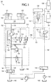
- FIG. 1 An exemplary circuit diagram of a load-lifting system 100 having a free lift mast and various hydraulic valve circuitry adapted for weight-responsive control of load-clamping members in such a system is provided in FIG. 1 .
- the system 100 generally includes one or more fluid power actuators 101, 103 capable of operating in unison to apply a gripping force to a load held between load-clamping members (not shown).
- At least one elongate, longitudinally-extensible fluid power lifting device shown schematically in FIG. 1 has a free lift stage 154 and a main lift stage 156.
- the load-clamping members may comprise paper roll clamp arms or any type of load-clamping members controllable by at least one fluid power actuator.
- the load-clamping members may comprise clamping arms in a carton clamp attachment.
- the load-lifting system 100 will be described in the context of a paper roll clamp attachment having a pair of load-clamping members arranged for operation in tandem, each load-clamping member controlled by one of the fluid power actuators 101, 103.
- the fluid power actuators 101, 103 may be configured for closing the load-clamping members as hydraulic fluid is introduced into the head sides of the fluid power actuators (or cylinders) 101, 103 via fluid lines (or hydraulic fluid conduits) 118, 120 and as hydraulic fluid is concurrently exhausted from the rod sides of the fluid power actuators 101, 103 via fluid lines 122, 124.
- Each of the power actuators 101, 103 may be controlled by a load-clamping valve assembly 126, which comprises hydraulic circuitry for closing or opening the load-clamping members.
- the specific circuitry used for the load-clamping valve 126 may comprise conventional circuitry for operating at least one of the power actuators 101, 103 for selectively closing or opening load-clamping member in response to at least one load-clamp-closing line (or hydraulic fluid conduit) 130 and at least one load-clamp-opening line 132.
- the load-clamping valve assembly 126 may, for example, include pilot-operated check valves and associated circuitry for controlling the clamping members of a paper roll clamp attachment.
- the load-clamping valve assembly 126 may include pilot-operated check valves and a fluid divider/combiner for controlling the clamping members of a carton clamp attachment.
- the lifting system 100 includes at least one elongate, longitudinally-extensible fluid power lifting device 154, 156, which has a free lift stage 154 and at least one main lift stage 156.
- the lifting device 154, 156 may be a single, multiple stage fluid power device having a free lift range of motion (shown schematically in FIG. 1 as 154 ) and at least one main lift range of motion (shown schematically in FIG. 1 as 156).
- the lifting device 154, 156 may, however, comprise an assembly of fluid power devices configured to have a free lift range of longitudinal movement for lifting the load-clamping members without unfolding of the mast and at least one main lift range of longitudinal movement whereby the mast unfolds as the lifting device extends.
- the free lift stage 154 requires a lower fluid pressure in line 158 for extensible actuation than the main lift stage 156 because the free lift stage 154 piston has a larger pressure surface area than the main lift stage 156 piston. Consequently, increasing hydraulic fluid to line 158 causes extension of the free lift stage 154 until its end of travel, after which increasing fluid to line 158 causes the main lift stage 156 to begin to extend.
- the hydraulic valve circuitry in FIG. 1 is shown grouped into three different modules or valve assemblies 128, 150, and 152, although various components may be grouped differently or grouped into a different number of modules or valve assemblies.
- the circuitry in 150 and 152 may, for example, comprise a single module or valve assembly. Further, portions of the circuitry in FIG. 1 may be used independently or with substituted circuitry. For example, the circuitry in 150 and 152 may be used with circuitry different than that shown in 128.
- the hydraulic valve circuitry grouped into the valve assembly 128, as shown, comprises circuitry for receiving a sensed load weight in line 168 from hydraulic circuitry associated with the lifting device 154, 156, and for using the sensed load weight for weight-responsive control of the load-clamping members.
- the hydraulic valve circuitry grouped into the valve assemblies 150 and 152 include circuitry for ensuring that the sensed load weight received in line 168 is equalized so as to be substantially independent of the longitudinally-extensible position of the lifting device 154, 156, and for enabling the cylinder or cylinders that comprise the lifting device 154, 156 to act as accumulators when the load-clamping 134 and load-lifting 146 selector valves are closed, thereby providing the load-lifting system 100 with full-time automatic weight-responsive force control of the load-clamping members.
- the hydraulic valve circuitry shown in the valve assembly 128 includes load-clamp-closing circuitry for receiving hydraulic fluid from a load-clamping selector valve 134.
- a load-clamping selector valve 134 For example, an operator of a lift truck equipped with a load-lifting system 100 for handling paper rolls may initiate closure of the load-clamping members by moving a load-clamping selector valve 134 to cause hydraulic fluid to flow from pump 142 into load-clamp-closing line 136, unseat the pilot-operated valve 190, and continue flowing to the load-clamping valve 126 via first fluid conduit 186 and then fluid conduit 130. As the fluid is introduced into the load-clamp-closing line 130, hydraulic fluid is concurrently exhausted through the load-clamp-opening line 132.
- the spring biased, normally open two-way valve 196 provides a path for fluid exhausted through the load-clamp-opening line 132 to return to the reservoir (or tank) 140.
- the two-way valve 196 is shown piloted from the load-clamp-opening line 138 causing the valve to move to a closed, no flow position when the load-clamping selector valve 134 is positioned for increasing fluid pressure in the load-clamp-opening line 138.
- Safety relief valve 144 is provided to return fluid back to the reservoir 140 if excessive pressure develops in the system 100.
- hydraulic pressure in the load-clamp-closing line 136 increases to a desired threshold (or starting) gripping pressure by an adjustable pressure relief valve 194 or other suitable valve.
- the pressure relief valve 194 may be set to limit the load-clamp-closing line 136 to 44.81 bar (650 psi) so that hydraulic fluid from the load-clamping selector valve 134 exceeding this limit is returned to the lift truck reservoir 140 rather than allowed to continue to increase the gripping pressure imposed on the clamped load.
- the fluid pressure sensed immediately downstream of the pilot-operated check valve 190, at 184 also increases up to the threshold pressure.
- the pilot line 174 receives the sensed pressure at 184 for controlling the position of two pilot-operated, adjustably spring biased two-position valves 172, 176, which are used to selectively control the range of fluid pressure accepted from line 168 and hydraulic circuitry associated with the lifting device 154, 156.
- the valve 172 is preferably used to set a lower pressure limit below which the load-clamp-closing circuitry is hydraulically decoupled from the load-lifting circuitry
- the valve 176 is preferably used to set a maximum clamping pressure above which the load-clamp-closing circuitry is hydraulically decoupled from the load-lifting circuitry.
- the two-position valve 176 is shown as a normally open valve, allowing fluid flow unless piloted by line 174 into a closed or no fluid flow state, whereas the two-position valve 172 is shown as a normally closed valve, blocking fluid flow unless piloted by line 174 into an open, fluid flow state.
- Each of the two-position valves 172, 176 is spring biased so as to remain in its normal state until the pilot line pressure exceeds the setting of the spring resistance. Pressure in the load-clamp-opening line 132 and spring override line 170 causes the valves 172, 176 to return to their normal state. Pressure in the load-clamp-opening line 132, 138 also unseats the check valve 190 via pilot line 192 allowing fluid to drain from the load-clamp-closing circuitry.
- the spring resistance setting for valve 172 is less than the threshold or starting pressure setting for the pressure relief valve 194 yet high enough to prevent the load-clamping members from drifting downward as they are being closed for gripping the load.
- Typical spring resistance settings may be 41.37 bar (600 psi) for the spring in valve 172 and 124.1 bar (1800 psi) for the spring in valve 176.
- valves 172 and 176 When both valves 172 and 176 are open, fluid pressure from line 168, and thereby the weight of the load, may be sensed at 180. Until valve 172 opens, the pressure in the load-clamp-closing circuitry is decoupled from pressure in the hoist lines 148 and 168. Only when both of the two-position valves 176 and 172 are open is fluid from line 168 able to be received into the load-clamp-closing circuitry at 180. The check valve 178 prevents fluid from the load-clamp-closing circuitry from flowing through line 168 back into the load-lifting circuitry.
- the check valve 182 prevents fluid from the line 168 from flowing upstream in the load-clamp-closing circuitry, instead forcing fluid to flow through the pressure regulating valve 188.
- the pressure regulating valve 188 may be used to adjust the clamping pressure applied by the load-clamping members in relation to weight-proportional fluid pressure received through the line 168. For example, for a lifting system having larger capacity fluid power actuators 101, 103, the weight-proportional hydraulic pressure received from the line 168 may result in excessive gripping forces exerted on the load. In such cases the pressure regulating valve 188 may be used to reduce the maximum pressure available for gripping the load.
- valve 188 Any suitable type of pressure regulating valve variably responsive to the pressure in line 168 can be used in the position of valve 188, including one or more pilot-controlled relief valves or pressure reducing valves.
- the load-clamping selector valve 134 is returned to its centered, unactuated position, and the hoist or load-lifting selector valve 146 is moved to allow hydraulic fluid to flow from pump 142 into hoist actuating line 148 for extending the lifting device 154, 156 to lift the load.
- the fluid conduits 148, 158, and 168 are simply interconnected together, the relationship between load weight sensed at line 168 and the hydraulic pressure in the line 168 would vary depending upon the position of the lifting device 154, 156 because lifting the load in free lift 154 requires less hydraulic pressure than lifting the same load in main lift 156.
- the main lift stage 156 may, for example, require an additional 27.58 bar (400 psi0 of hydraulic pressure for activation. Consequently, the load weight signal available from such a lifting system varies depending upon whether the lifting device is in free lift or main lift.
- the hydraulic valve circuitry grouped into the valve assemblies 150 and 152 includes circuitry for ensuring that the sensed load weight received in line 168 is equalized so as to be substantially independent of the longitudinally-extensible position of the lifting device 154, 156.
- the exemplary valve assembly 150 includes a pressure-differential regulating valve 164 that compensates for the difference in actuation pressures between free lift cylinder 154 and main lift cylinder 156.
- the pressure regulating valve 164 may be adjusted, for example, to reduce the pressure in line 158 by 400 psi to operate the free lift cylinder 154, as compared with the higher downstream pressure required in line 158 to operate the smaller-area piston of the main lift cylinder 156.
- the pressure in line 148 is effectively intensified by the valve 164 so as to equalize the sensed load weight in line 168 to that which naturally occurs during operation of the main lift cylinder 156.
- a valve assembly 152 comprising a normally closed, plunger-activated two-way valve 160, is mounted to a cross member of the lowest (fixed) mast section below a cross member 198 of the movable main lift telescoping section of the mast.
- the main lift cross member 198 moves upwardly from the plunger 162 as the main lift stage 156 is actuated, thereby allowing the pressure in line 168 to move the two-way valve 160 to its open position. This enables fluid to bypass the equalizing valve 164, eliminating its pressure-reducing effect.
- the fluid is able to bypass the equalizing valve 164 so that the higher pressure in line 148 is available for actuating the main lift stage 156 of the lifting device 154, 156.
- Other types of valves or components may be used for bypassing the equalizing valve 164 when the lifting device 154, 156 is in its main lift 156 range of motion.
- hydraulic fluid is permitted to flow through the two-way (or bypassing) valve 160.
- the two-way valve 160 becomes closed (when the main lift cross member 198 depresses the plunger 162 ) fluid is able to bypass the equalizing valve 164 by flowing through the check valve 166, which in turn provides a path for hydraulic fluid to exhaust from the free lift stage 154 as the lifting device 154, 156 is further retracted.
- the check valve 166 also enables the cylinder or cylinders that comprise the lifting device 154, 156 to act as accumulators when the load-clamping 134 and load-lifting 146 selector valves are closed, thereby providing the load-lifting system 100 with full-time automatic weight-responsive force control of the load-clamping members. If, for example, there is an increase in the magnitude of sensed load weight, the check valve 166 enables fluid from the lifting device 154, 156 to automatically increase fluid to the load-clamp-closing circuitry through line 168 without concurrent actuation of either the load-clamping 134 or load-lifting 146 selector valves.
- the check valve 166 enables fluid from the lifting device 154, 156 to automatically increase fluid to the load-clamp-closing circuitry without concurrent actuation of either the load-clamping 134 or load-lifting 146 selector valves.
- valve assembly 152 comprising a plunger-activated two-way valve 160
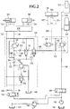
- the valve assembly 152 may comprise, for example, a switch 204 that is responsive to the extensible position of the mast and that provides an activation signal via electric wires 206 to a normally open, solenoid-activated two-way valve 200 in valve assembly 150, as shown in FIG. 2 .
- the solenoid-activated two-way valve 200 is shown in FIG. 2 in an activated, closed position to be consistent with FIG. 1 , which shows the two-way valve 160 in a closed (blocked) position for operation of the lifting device 154, 156 in its free lift 154 range of movement.
- a switch triggering element or other device such as, for example, a target 202 may be mounted to a cross member 198 of the movable main lift section of the mast and a switch 204 (such as a proximity switch) may be mounted on the lower or fixed portion of the mast.
- a proximity switch 204 provides an activation signal causing the solenoid-activated two-way valve 200 to remain in an activated, closed position throughout extension of the lifting device 154, 156 in its free lift 154 range of movement.
- the main lift cross member 198 moves upwardly away from the fixed portion of the mast, thereby separating the switch elements and causing de-activation of the solenoid-activated two-way valve 200, which in turn moves the two-way valve 200 to its open position.
- This enables fluid to bypass the equalizing valve 164, eliminating its pressure-reducing effect.
- the fluid is able to bypass the equalizing valve 164 so that the higher pressure in line 148 is available for actuating the main lift stage 156 of the lifting device 154, 156.
- switch 204 and solenoid valve 200 are electrical, they are both mounted on portions of the mast or lift truck which are fixed and do not move in response to mast extension, thereby avoiding the need for any electrical conductor which must move in response to mast extension and would therefore be exposed to hazards and durability problems.
- Other types of valves or components may be used for bypassing the equalizing valve 164 when the lifting device 154, 156 is in its main lift 156 range of motion.
- hydraulic fluid is permitted to flow through the two-way (or bypassing) valve 200. Once the two-way valve 200 becomes closed fluid is able to bypass the equalizing valve 164 by flowing through the check valve 166, which in turn provides a path for hydraulic fluid to exhaust from the free lift stage 154 as the lifting device 154, 156 is further retracted.
- additional main lift stages may be accommodated by adding equalization and bypassing valves to compensate for the higher actuation pressures required so that the sensed load weight at line 168 remains independent of the longitudinally-extensible position of the lifting device.
- the lifting device includes a second main lift stage beyond the single main lift stage 156 shown in FIG. 1
- another equalization valve may be added in series with equalizing valve 164, and another valve for bypassing the added equalizing valve may be added for actuation of the additional (second) main lift stage when the first main lift stage 156 reaches its end of travel.
Landscapes
- Engineering & Computer Science (AREA)
- Structural Engineering (AREA)
- Transportation (AREA)
- Mechanical Engineering (AREA)
- Life Sciences & Earth Sciences (AREA)
- Geology (AREA)
- Civil Engineering (AREA)
- Chemical & Material Sciences (AREA)
- Combustion & Propulsion (AREA)
- Physics & Mathematics (AREA)
- General Physics & Mathematics (AREA)
- Forklifts And Lifting Vehicles (AREA)
- Fluid-Pressure Circuits (AREA)
Abstract
Description
- This disclosure relates generally to hydraulic valve circuits for use with material handling equipment and, more particularly, to hydraulic valve circuits adapted for weight-responsive control of clamping members associated with material handling equipment having free lift masts.
- Standard forklifts and other types of material handling equipment typically have mast assemblies for hoisting or lifting a load from one height to another, and such mast assemblies are typically configured to receive a variety of attachments that may be designed for handling particular types of loads. For example, load-clamping attachments such as carton clamps or paper roll clamps may be used, each having hydraulically controllable load-clamping members for imparting sufficient gripping forces on the sides of a load to allow lifting and carrying the load from one place to another.
- Mast assemblies are typically one of two general types -- "free lift" or "non-free lift." Free lift masts permit lifting a load from one height to another throughout a "free lift" range of motion without a corresponding change in the overall height of the mast assembly. Lifting the load beyond the free lift range of motion requires the mast to telescope so as to extend the range of lifting. The mast may have several stages which telescope in succession, one after the other. Each stage will generally have one or more extensible hydraulic cylinders which, when activated, extend fully before activation of the one or more extensible hydraulic cylinders associated with the next stage. The hydraulic cylinders in each successive stage usually require higher hoist pressures for activation than cylinders of the preceding stage. Consequently, in a free lift mast having, for example, a free lift range of lifting motion and a main lift range of lifting motion, the main lift cylinder or cylinders will not begin to extend until the free lift cylinder or cylinders have reached their fully extended position.
- By contrast, non-free lift masts begin to telescope immediately as the load is lifted. Such telescoping of the mast is undesirable in overhead constrained environments. For example, the interior of enclosed tractor trailers may be limited to, for example, an inside height of 264 cm (104 inches). If the particular lift truck has a collapsed mast height of between 200 TO 213 cm (79 to 84 inches), as is common for counterbalanced sit-down lift trucks, there may be only 50.8 to 63.5 cm (20 to 25 inches) of vertical space available for the mast to telescope before further telescoping of the mast interferes with the ceiling of the trailer.
- In part because free lift masts typically require stepped or progressively higher hoist line pressures for extending the mast beyond the free lift range of motion, principally hydraulic control systems adapted to utilize hoist line pressures for sensing load weight and correspondingly regulating gripping forces automatically in response to such pressures have not been achieved with such masts. Alternative designs using electronic controllers for such gripping force regulation have disadvantages such as higher unit costs and added system complexity, as well as the requirement for electrical conductors, such as the electronic controller disclosed in
U.S. Patent No. 6,421,816 , which must be movable in response to mast extension. Therefore, different hydraulic valve circuits are needed for automatic weight-responsive force control of load-clamping members associated with material handling systems having free lift masts. An example of a hydraulic circuit for load-clamping can be found in European patent application publication No.EP1657030A1 . - In accordance with a first aspect of the invention, there is provided a hydraulic valve circuit adapted for controlling a load-gripping device as defined in
claim 1. Optional features of the hydraulic valve circuit are set out in the claims dependent onclaim 1. - In accordance with a second aspect of the invention, there is provided a hydraulic valve circuit adapted for sensing a weight magnitude of a load supported by at least one elongate, longitudinally-extensible lifting device having a fluid power lifting actuator whose fluid pressure is variably dependent on said weight magnitude and also variably dependent on different longitudinally-extensible positions of said lifting device, said hydraulic valve circuit comprising at least one fluid valve assembly hydraulically interconnectable with said fluid power lifting actuator and capable of hydraulically sensing said weight magnitude from said fluid pressure automatically substantially irrespective of said different longitudinally-extensible positions of said lifting device.
- In accordance with a third aspect of the invention, there is provided a hydraulic valve circuit adapted for controlling a load-gripping device having a fluid power gripping actuator capable of applying automatically variable load weight responsive gripping force to a load in response to a manually activated load-clamping selector valve, and further having at least one elongate, longitudinally-extensible lifting device having a fluid power lifting actuator capable of supporting said load by fluid pressure in said lifting actuator which is variably dependent on a weight magnitude of said load and also variably dependent on different longitudinally-extensible positions of said lifting device, said hydraulic valve circuit comprising at least one fluid valve assembly hydraulically interconnectable with said load-gripping device and capable of transferring fluid from said fluid power lifting actuator to said fluid power gripping actuator to thereby increase said gripping force on said load irrespective of said different longitudinally-extensible positions of said lifting device, without concurrent manual actuation of said load-clamping selector valve and without concurrent manual actuation of said load-lifting selector valve.
- In accordance with a fourth aspect of the invention, there is provided a hydraulic valve circuit adapted for sensing a weight magnitude of a load supported by at least one elongate, longitudinally-extensible lifting device having a fluid power lifting actuator whose fluid pressure is variably dependent on said weight magnitude and also variably dependent on different longitudinally-extensible positions of said lifting device, said hydraulic valve circuit comprising at least one fluid valve assembly hydraulically interconnectable with said fluid power lifting actuator and capable of automatically converting said fluid pressure to a pressure that is variably dependent on said weight magnitude and substantially independent of said longitudinally-extensible position of said lifting device.
- For a more complete understanding of the present invention, the drawings herein illustrate exemplary hydraulic circuitry in accordance with various embodiments of the invention. The drawings, however, do not limit the scope of the invention.
-
FIG. 1 is a schematic of a load-lifting system having a free lift mast and various hydraulic valve circuitry adapted for weight-responsive control of load-clamping members, in accordance with various embodiments. -
FIG. 2 is the schematic inFIG. 1 with a solenoid-controlled two-way hydraulic valve as an exemplary alternative to the plunger-activated valve inFIG. 1 . - In the following detailed description, numerous specific details are set forth in order to provide a thorough understanding of various embodiments. However, those skilled in the art will understand that the present invention may be practiced without these specific details, that the present invention is not limited to the described embodiments, and that the present invention may be practiced in a variety of alternate embodiments. In other instances, well known methods, procedures, components, and systems have not been described in detail.
- An exemplary circuit diagram of a load-
lifting system 100 having a free lift mast and various hydraulic valve circuitry adapted for weight-responsive control of load-clamping members in such a system is provided inFIG. 1 . Thesystem 100, as shown, generally includes one or morefluid power actuators FIG. 1 has afree lift stage 154 and amain lift stage 156. Manually operated load-clamping 134 and load-lifting 146 selector valves, and various hydraulic valve circuitry for controlling the operation of thefluid power actuators lifting device selector valves - The load-clamping members, at least one of which is controllable by one or more of the
fluid power actuators lifting system 100 will be described in the context of a paper roll clamp attachment having a pair of load-clamping members arranged for operation in tandem, each load-clamping member controlled by one of thefluid power actuators fluid power actuators fluid power actuators fluid lines - Each of the
power actuators clamping valve assembly 126, which comprises hydraulic circuitry for closing or opening the load-clamping members. The specific circuitry used for the load-clamping valve 126 may comprise conventional circuitry for operating at least one of thepower actuators opening line 132. The load-clamping valve assembly 126 may, for example, include pilot-operated check valves and associated circuitry for controlling the clamping members of a paper roll clamp attachment. As another example, the load-clamping valve assembly 126 may include pilot-operated check valves and a fluid divider/combiner for controlling the clamping members of a carton clamp attachment. - As shown schematically in
FIG. 1 , thelifting system 100 includes at least one elongate, longitudinally-extensible fluidpower lifting device free lift stage 154 and at least onemain lift stage 156. Thelifting device FIG. 1 as 154) and at least one main lift range of motion (shown schematically inFIG. 1 as 156). Thelifting device free lift stage 154 requires a lower fluid pressure inline 158 for extensible actuation than themain lift stage 156 because thefree lift stage 154 piston has a larger pressure surface area than themain lift stage 156 piston. Consequently, increasing hydraulic fluid toline 158 causes extension of thefree lift stage 154 until its end of travel, after which increasing fluid toline 158 causes themain lift stage 156 to begin to extend. - The hydraulic valve circuitry in
FIG. 1 is shown grouped into three different modules orvalve assemblies FIG. 1 may be used independently or with substituted circuitry. For example, the circuitry in 150 and 152 may be used with circuitry different than that shown in 128. - The hydraulic valve circuitry grouped into the
valve assembly 128, as shown, comprises circuitry for receiving a sensed load weight inline 168 from hydraulic circuitry associated with thelifting device valve assemblies line 168 is equalized so as to be substantially independent of the longitudinally-extensible position of thelifting device lifting device lifting system 100 with full-time automatic weight-responsive force control of the load-clamping members. - The hydraulic valve circuitry shown in the
valve assembly 128 includes load-clamp-closing circuitry for receiving hydraulic fluid from a load-clamping selector valve 134. For example, an operator of a lift truck equipped with a load-lifting system 100 for handling paper rolls may initiate closure of the load-clamping members by moving a load-clamping selector valve 134 to cause hydraulic fluid to flow frompump 142 into load-clamp-closing line 136, unseat the pilot-operatedvalve 190, and continue flowing to the load-clamping valve 126 viafirst fluid conduit 186 and thenfluid conduit 130. As the fluid is introduced into the load-clamp-closing line 130, hydraulic fluid is concurrently exhausted through the load-clamp-opening line 132. The spring biased, normally open two-way valve 196 provides a path for fluid exhausted through the load-clamp-opening line 132 to return to the reservoir (or tank) 140. The two-way valve 196 is shown piloted from the load-clamp-opening line 138 causing the valve to move to a closed, no flow position when the load-clamping selector valve 134 is positioned for increasing fluid pressure in the load-clamp-opening line 138.Safety relief valve 144 is provided to return fluid back to thereservoir 140 if excessive pressure develops in thesystem 100. - As the load-clamping members close upon the load, imposing a gripping force upon the sides of the load, hydraulic pressure in the load-clamp-
closing line 136 increases to a desired threshold (or starting) gripping pressure by an adjustablepressure relief valve 194 or other suitable valve. For example, thepressure relief valve 194 may be set to limit the load-clamp-closing line 136 to 44.81 bar (650 psi) so that hydraulic fluid from the load-clampingselector valve 134 exceeding this limit is returned to thelift truck reservoir 140 rather than allowed to continue to increase the gripping pressure imposed on the clamped load. - As the fluid pressure increases in the load-clamp-
closing line 136 up to the setting of thepressure relief valve 194, i.e. the threshold pressure, the fluid pressure sensed immediately downstream of the pilot-operatedcheck valve 190, at 184, also increases up to the threshold pressure. Thepilot line 174 receives the sensed pressure at 184 for controlling the position of two pilot-operated, adjustably spring biased two-position valves line 168 and hydraulic circuitry associated with thelifting device valve 172 is preferably used to set a lower pressure limit below which the load-clamp-closing circuitry is hydraulically decoupled from the load-lifting circuitry, and thevalve 176 is preferably used to set a maximum clamping pressure above which the load-clamp-closing circuitry is hydraulically decoupled from the load-lifting circuitry. The two-position valve 176 is shown as a normally open valve, allowing fluid flow unless piloted byline 174 into a closed or no fluid flow state, whereas the two-position valve 172 is shown as a normally closed valve, blocking fluid flow unless piloted byline 174 into an open, fluid flow state. Each of the two-position valves opening line 132 andspring override line 170 causes thevalves opening line check valve 190 viapilot line 192 allowing fluid to drain from the load-clamp-closing circuitry. - Preferably the spring resistance setting for
valve 172 is less than the threshold or starting pressure setting for thepressure relief valve 194 yet high enough to prevent the load-clamping members from drifting downward as they are being closed for gripping the load. Typical spring resistance settings may be 41.37 bar (600 psi) for the spring invalve 172 and 124.1 bar (1800 psi) for the spring invalve 176. Once the fluid pressure sensed at 184 reaches the spring setting ofvalve 172, or 41.37 bar (600 psi), for example,valve 172 opens to allow fluid pressure to be sensed downstream of nowopen valve 172, downstream of the normallyopen valve 176, and also downstream ofcheck valve 178. When bothvalves line 168, and thereby the weight of the load, may be sensed at 180. Untilvalve 172 opens, the pressure in the load-clamp-closing circuitry is decoupled from pressure in the hoistlines position valves line 168 able to be received into the load-clamp-closing circuitry at 180. Thecheck valve 178 prevents fluid from the load-clamp-closing circuitry from flowing throughline 168 back into the load-lifting circuitry. - The
check valve 182 prevents fluid from theline 168 from flowing upstream in the load-clamp-closing circuitry, instead forcing fluid to flow through thepressure regulating valve 188. Thepressure regulating valve 188 may be used to adjust the clamping pressure applied by the load-clamping members in relation to weight-proportional fluid pressure received through theline 168. For example, for a lifting system having larger capacityfluid power actuators line 168 may result in excessive gripping forces exerted on the load. In such cases thepressure regulating valve 188 may be used to reduce the maximum pressure available for gripping the load. Other factors such as the fragility and stability of certain types of loads, the size and capacity of the load-lifting cylinder or cylinders comprising thelifting device pressure equalizing circuitry 150 associated with thelifting device line 168. - Any suitable type of pressure regulating valve variably responsive to the pressure in
line 168 can be used in the position ofvalve 188, including one or more pilot-controlled relief valves or pressure reducing valves. - During a load-lifting operation, after the threshold pressure is reached for clamping the load the load-clamping
selector valve 134 is returned to its centered, unactuated position, and the hoist or load-liftingselector valve 146 is moved to allow hydraulic fluid to flow frompump 142 into hoistactuating line 148 for extending thelifting device fluid conduits line 168 and the hydraulic pressure in theline 168 would vary depending upon the position of thelifting device free lift 154 requires less hydraulic pressure than lifting the same load inmain lift 156. Themain lift stage 156 may, for example, require an additional 27.58 bar (400 psi0 of hydraulic pressure for activation. Consequently, the load weight signal available from such a lifting system varies depending upon whether the lifting device is in free lift or main lift. - The hydraulic valve circuitry grouped into the
valve assemblies line 168 is equalized so as to be substantially independent of the longitudinally-extensible position of thelifting device exemplary valve assembly 150 includes a pressure-differential regulating valve 164 that compensates for the difference in actuation pressures betweenfree lift cylinder 154 andmain lift cylinder 156. Thepressure regulating valve 164 may be adjusted, for example, to reduce the pressure inline 158 by 400 psi to operate thefree lift cylinder 154, as compared with the higher downstream pressure required inline 158 to operate the smaller-area piston of themain lift cylinder 156. During operation of thefree lift cylinder 154 the pressure inline 148 is effectively intensified by thevalve 164 so as to equalize the sensed load weight inline 168 to that which naturally occurs during operation of themain lift cylinder 156. - During
free lift 154, as the load is lifted without telescoping of the mast, themain lift stage 156 remains stationary. In one embodiment, avalve assembly 152, comprising a normally closed, plunger-activated two-way valve 160, is mounted to a cross member of the lowest (fixed) mast section below across member 198 of the movable main lift telescoping section of the mast. After thefree lift stage 154 reaches its upper end of travel, the mainlift cross member 198 moves upwardly from theplunger 162 as themain lift stage 156 is actuated, thereby allowing the pressure inline 168 to move the two-way valve 160 to its open position. This enables fluid to bypass the equalizingvalve 164, eliminating its pressure-reducing effect. As additional hydraulic fluid is introduced throughline 148 to continue lifting the load, the fluid is able to bypass the equalizingvalve 164 so that the higher pressure inline 148 is available for actuating themain lift stage 156 of thelifting device valve 164 when thelifting device main lift 156 range of motion. - When retracting the
lifting device main lift 156 range of movement, hydraulic fluid is permitted to flow through the two-way (or bypassing)valve 160. Once the two-way valve 160 becomes closed (when the mainlift cross member 198 depresses the plunger 162) fluid is able to bypass the equalizingvalve 164 by flowing through thecheck valve 166, which in turn provides a path for hydraulic fluid to exhaust from thefree lift stage 154 as thelifting device - The
check valve 166 also enables the cylinder or cylinders that comprise thelifting device system 100 with full-time automatic weight-responsive force control of the load-clamping members. If, for example, there is an increase in the magnitude of sensed load weight, thecheck valve 166 enables fluid from thelifting device line 168 without concurrent actuation of either the load-clamping 134 or load-lifting 146 selector valves. Similarly, if there is a decrease in the gripping force exerted on the load, thecheck valve 166 enables fluid from thelifting device - Although a
valve assembly 152 comprising a plunger-activated two-way valve 160 has been described, thevalve assembly 152 may comprise, for example, aswitch 204 that is responsive to the extensible position of the mast and that provides an activation signal viaelectric wires 206 to a normally open, solenoid-activated two-way valve 200 invalve assembly 150, as shown inFIG. 2 . The solenoid-activated two-way valve 200 is shown inFIG. 2 in an activated, closed position to be consistent withFIG. 1 , which shows the two-way valve 160 in a closed (blocked) position for operation of thelifting device free lift 154 range of movement. In one embodiment, a switch triggering element or other device such as, for example, atarget 202 may be mounted to across member 198 of the movable main lift section of the mast and a switch 204 (such as a proximity switch) may be mounted on the lower or fixed portion of the mast. In one embodiment, aproximity switch 204 provides an activation signal causing the solenoid-activated two-way valve 200 to remain in an activated, closed position throughout extension of thelifting device free lift 154 range of movement. After thefree lift stage 154 reaches its upper end of travel, the mainlift cross member 198 moves upwardly away from the fixed portion of the mast, thereby separating the switch elements and causing de-activation of the solenoid-activated two-way valve 200, which in turn moves the two-way valve 200 to its open position. This enables fluid to bypass the equalizingvalve 164, eliminating its pressure-reducing effect. As additional hydraulic fluid is introduced throughline 148 to continue lifting the load, the fluid is able to bypass the equalizingvalve 164 so that the higher pressure inline 148 is available for actuating themain lift stage 156 of thelifting device switch 204 andsolenoid valve 200 are electrical, they are both mounted on portions of the mast or lift truck which are fixed and do not move in response to mast extension, thereby avoiding the need for any electrical conductor which must move in response to mast extension and would therefore be exposed to hazards and durability problems. Other types of valves or components may be used for bypassing the equalizingvalve 164 when thelifting device main lift 156 range of motion. - When retracting the
lifting device main lift 156 range of movement, hydraulic fluid is permitted to flow through the two-way (or bypassing)valve 200. Once the two-way valve 200 becomes closed fluid is able to bypass the equalizingvalve 164 by flowing through thecheck valve 166, which in turn provides a path for hydraulic fluid to exhaust from thefree lift stage 154 as thelifting device - Although a two-stage (i.e. free lift and main lift) lifting device has been described, additional main lift stages may be accommodated by adding equalization and bypassing valves to compensate for the higher actuation pressures required so that the sensed load weight at
line 168 remains independent of the longitudinally-extensible position of the lifting device. For example, if the lifting device includes a second main lift stage beyond the singlemain lift stage 156 shown inFIG. 1 , another equalization valve may be added in series with equalizingvalve 164, and another valve for bypassing the added equalizing valve may be added for actuation of the additional (second) main lift stage when the firstmain lift stage 156 reaches its end of travel. - The terms and expressions which have been employed in the forgoing specification are used therein as terms of description and not of limitation, and there is no intention in the use of such terms and expressions of excluding equivalence of the features shown and described or portions thereof, it being recognized that the scope of the invention is defined and limited only by the claims which follow and the statements of invention above.
Claims (5)
- A hydraulic valve circuit adapted for controlling a load-gripping device having a fluid power gripping actuator (101, 103) capable of applying an automatically variable load weight responsive gripping force to a load in response to a manually activated load-clamping selector valve (134) of an elongate, longitudinally-extensible lifting device that lifts the load in response to a manually activated load-lifting selector valve (146), the load lifting device having a fluid power lifting actuator (154, 156) capable of supporting said load by fluid pressure in said lifting actuator which is variably dependent on a weight magnitude of said load and also variably dependent on different longitudinally-extensible positions of said lifting device, characterized by said hydraulic valve circuit comprising at least one fluid valve assembly (128) hydraulically interconnectable with said load-gripping device and capable of transferring fluid from said fluid power lifting actuator to said fluid power gripping actuator to thereby increase said gripping force on said load irrespective of said different longitudinally-extensible positions of said lifting device, without concurrent manual actuation of said load-clamping selector valve and without concurrent manual actuation of said load-lifting selector valve.
- The hydraulic valve circuit of claim 1 including a check valve (178) that allows fluid to flow from the fluid power lifting actuator to the fluid power gripping actuator and prevents fluid from flowing from the fluid power gripping actuator to the fluid power lifting actuator.
- The hydraulic valve circuit of any of the preceding claims and including at least one valve (172, 176) that limits the increase in said gripping force to a gripping magnitude between a lower threshold and an upper threshold.
- The hydraulic circuit of any of the preceding claims and including a regulating valve (188) that regulates the magnitude of the gripping force applied to the load as a function of the pressure in the fluid power lifting actuator.
- The hydraulic circuit of claim 4 including a check valve (182) that causes any said increase in said gripping force to be regulated by the pressure regulating valve.
Applications Claiming Priority (4)
| Application Number | Priority Date | Filing Date | Title |
|---|---|---|---|
| US24824508A | 2008-10-09 | 2008-10-09 | |
| US12/543,279 US9964428B2 (en) | 2008-10-09 | 2009-08-18 | Equalized hydraulic clamp force control |
| PCT/US2009/055539 WO2010042283A2 (en) | 2008-10-09 | 2009-08-31 | Equalized hydraulic clamp force control |
| EP09792115.9A EP2331449B1 (en) | 2008-10-09 | 2009-08-31 | Equalized hydraulic clamp force control |
Related Parent Applications (2)
| Application Number | Title | Priority Date | Filing Date |
|---|---|---|---|
| EP09792115.9A Division EP2331449B1 (en) | 2008-10-09 | 2009-08-31 | Equalized hydraulic clamp force control |
| EP09792115.9A Division-Into EP2331449B1 (en) | 2008-10-09 | 2009-08-31 | Equalized hydraulic clamp force control |
Publications (2)
| Publication Number | Publication Date |
|---|---|
| EP3524568A1 true EP3524568A1 (en) | 2019-08-14 |
| EP3524568B1 EP3524568B1 (en) | 2022-04-27 |
Family
ID=41381581
Family Applications (2)
| Application Number | Title | Priority Date | Filing Date |
|---|---|---|---|
| EP09792115.9A Active EP2331449B1 (en) | 2008-10-09 | 2009-08-31 | Equalized hydraulic clamp force control |
| EP19158194.1A Active EP3524568B1 (en) | 2008-10-09 | 2009-08-31 | Equalized hydraulic clamp force control |
Family Applications Before (1)
| Application Number | Title | Priority Date | Filing Date |
|---|---|---|---|
| EP09792115.9A Active EP2331449B1 (en) | 2008-10-09 | 2009-08-31 | Equalized hydraulic clamp force control |
Country Status (8)
| Country | Link |
|---|---|
| US (3) | US9964428B2 (en) |
| EP (2) | EP2331449B1 (en) |
| JP (1) | JP5809561B2 (en) |
| CN (2) | CN102159491B (en) |
| BR (1) | BRPI0907862A2 (en) |
| CA (2) | CA2732257C (en) |
| ES (2) | ES2914407T3 (en) |
| WO (1) | WO2010042283A2 (en) |
Families Citing this family (20)
| Publication number | Priority date | Publication date | Assignee | Title |
|---|---|---|---|---|
| US9964428B2 (en) | 2008-10-09 | 2018-05-08 | Cascade Corporation | Equalized hydraulic clamp force control |
| CN103508382B (en) * | 2012-06-26 | 2015-10-21 | 安庆联动属具股份有限公司 | Many grades of regulators |
| CN102900715B (en) * | 2012-10-08 | 2015-06-24 | 北京索普液压机电有限公司 | Hydraulic control system for forklift, and forklift |
| US8755929B2 (en) * | 2012-10-29 | 2014-06-17 | Cascade Corporation | Interactive clamp force control system for load handling clamps |
| US9114963B2 (en) * | 2013-02-26 | 2015-08-25 | Cascade Corporation | Clamping surface positioning system for mobile load-handling clamps |
| DE102013108495B4 (en) * | 2013-08-07 | 2017-08-24 | Mhwirth Gmbh | Lift brake system |
| DE102014001426A1 (en) * | 2014-02-05 | 2015-08-06 | Kaup Gmbh & Co. Kg | Hitch and method |
| CN104033450B (en) * | 2014-05-28 | 2016-05-25 | 广西柳工机械股份有限公司 | Hydraulic control unloader valve |
| DE102015201993A1 (en) * | 2015-02-05 | 2016-08-11 | Zwick Gmbh & Co. Kg | Material sample holder with control unit |
| WO2017048762A1 (en) | 2015-09-14 | 2017-03-23 | Maxion Wheels U.S.A. Llc | Vehicle wheel assembly having improved monitoring capabilities for various vehicle conditions and monitoring device for accomplishing such monitoring |
| US10017366B2 (en) * | 2016-04-01 | 2018-07-10 | Cascade Corporation | Clamp having a load-clamping hydraulic cylinder with multiple telescopically extensible stages adapted to apply load clamping force alternatively responsive to load-lifting force or load size |
| US10494241B2 (en) * | 2016-09-16 | 2019-12-03 | Cascade Corporation | Hydraulic clamping systems having load side-shifting variably responsive to load weight |
| CN108762062A (en) * | 2018-05-24 | 2018-11-06 | 安庆联动属具股份有限公司 | A kind of lift truck attachment clamping force self-adaptation control method and system |
| CN109231086A (en) * | 2018-10-18 | 2019-01-18 | 合肥搬易通科技发展有限公司 | A kind of pallet stacking car hydraulic system of certain time interior control clamping force size |
| US11530123B2 (en) * | 2018-12-21 | 2022-12-20 | Rightline Equipment, Inc. | Lift truck attachment with smart clamp |
| US11034565B2 (en) | 2019-03-05 | 2021-06-15 | Cascade Corporation | Revolving paper roll clamp with short arm drift prevention |
| US11220417B2 (en) * | 2019-05-22 | 2022-01-11 | Cascade Corporation | Hybrid clamp force control for lift truck attachment |
| US11655130B2 (en) | 2019-05-22 | 2023-05-23 | Cascade Corporation | Synchronized hybrid clamp force controller for lift truck attachment |
| CA3091493A1 (en) * | 2019-08-29 | 2021-02-28 | The Raymond Corporation | Variable hydraulic pressure relief systems and methods for a material handling vehicle |
| CN111022412B (en) * | 2019-12-25 | 2022-06-21 | 南京三强电子通信技术有限公司 | Balance cylinder for assembling airplane wing |
Citations (5)
| Publication number | Priority date | Publication date | Assignee | Title |
|---|---|---|---|---|
| US6421816B1 (en) | 1998-04-07 | 2002-07-16 | Matsushita Electric Industrial Co., Ltd. | Semiconductor device, semiconductor device design method, semiconductor device design method recording medium, and semiconductor device design support system |
| US20050072474A1 (en) * | 2003-10-01 | 2005-04-07 | Jervis Mark J. | Valve assembly for attenuating bounce of hydraulically driven members of a machine |
| EP1657030A1 (en) | 1998-10-07 | 2006-05-17 | Cascade Corporation | Adaptive load-clamping system |
| US20070017364A1 (en) * | 2005-07-04 | 2007-01-25 | Veneziani Luciano | Hydraulic control unit for the arms of a grip and grip including said hydraulic unit |
| US20070044650A1 (en) * | 2005-08-31 | 2007-03-01 | Caterpillar Inc. | Valve having a hysteretic filtered actuation command |
Family Cites Families (32)
| Publication number | Priority date | Publication date | Assignee | Title |
|---|---|---|---|---|
| DE942349C (en) | 1953-10-03 | 1956-05-03 | Hans Still Ag | Gripper for stacked goods, especially for floor handling equipment |
| AT311769B (en) * | 1972-04-06 | 1973-12-10 | Voest Ag | Hydraulic forge charging pliers |
| US4000683A (en) * | 1975-05-27 | 1977-01-04 | Caterpillar Tractor Co. | Hydraulic load lifting system |
| CA1106733A (en) * | 1977-07-13 | 1981-08-11 | Clark Equipment Company | Pressure control mechanism for a grapple skidder |
| US4161256A (en) * | 1977-10-04 | 1979-07-17 | Cascade Corporation | Fluid power system having multiple, separately controllable double-acting fluid motors and reduced number of fluid conduits |
| JPS5490752A (en) * | 1977-12-27 | 1979-07-18 | Nissan Motor Co Ltd | Safety circuit for side clamp |
| US4177000A (en) * | 1978-03-22 | 1979-12-04 | Cascade Corporation | Rotatable load clamp adapted for selective load positioning in response to selective rotational positioning of clamp |
| JPS6218637Y2 (en) * | 1980-11-25 | 1987-05-13 | ||
| US4431385A (en) | 1981-11-16 | 1984-02-14 | Hare Louis R O | Solar displacement pump |
| DD206661A3 (en) | 1982-02-23 | 1984-02-01 | Bauakademie Ddr | LOADING AND CARRYING DEVICE |
| JPS5916022A (en) * | 1982-07-16 | 1984-01-27 | Uchida Yuatsu Kiki Kogyo Kk | Backlash removing circuit device |
| US4491190A (en) * | 1983-01-31 | 1985-01-01 | Mayfield Harvey G | Weight measurement apparatus |
| JPS6072499U (en) * | 1983-10-22 | 1985-05-22 | 株式会社大阪タイユー | Article lifting device |
| US4663738A (en) | 1984-12-04 | 1987-05-05 | Xerox Corporation | High density block oriented solid state optical memories |
| JPS61139996U (en) * | 1985-02-19 | 1986-08-29 | ||
| JPS6490752A (en) | 1987-10-02 | 1989-04-07 | Canon Kk | Multi color printer |
| JPH0636076Y2 (en) * | 1988-03-29 | 1994-09-21 | 株式会社をくだ屋技研 | Hand lift truck |
| US4860512A (en) | 1988-06-15 | 1989-08-29 | Therma-Tru Corp. | Compression molded door assembly |
| JP2915675B2 (en) | 1992-02-26 | 1999-07-05 | 三菱重工業株式会社 | Forklift control device |
| US5417464A (en) * | 1993-12-10 | 1995-05-23 | Cascade Corporation | Slip-correcting load-clamping system |
| JP3175513B2 (en) * | 1994-12-28 | 2001-06-11 | 日産自動車株式会社 | Control circuit of hydraulic cylinder in forklift |
| US5666295A (en) * | 1996-01-05 | 1997-09-09 | Sentek Products | Apparatus and method for dynamic weighing of loads in hydraulically operated lifts |
| SE505210C2 (en) * | 1996-04-26 | 1997-07-14 | Nymek Ab | Control for a load handling device |
| US6843636B2 (en) * | 1998-10-07 | 2005-01-18 | Cascade Corporation | Adaptive load-clamping system |
| CA2282198C (en) * | 1998-10-07 | 2003-06-10 | Cascade Corporation | Adaptive load-clamping system |
| DE10259470B4 (en) * | 2002-12-19 | 2005-08-11 | Jungheinrich Aktiengesellschaft | Method for determining the load weight on the load bearing means of a hydraulic lifting device |
| US7412919B2 (en) * | 2004-08-04 | 2008-08-19 | Loron, Inc. | Hydraulic force control system for clamping assembly |
| US7909563B2 (en) * | 2004-11-30 | 2011-03-22 | Cascade Corporation | Fork positioner |
| SE528276C2 (en) | 2005-02-14 | 2006-10-10 | Hans Nilsson | Clamp force control |
| CA2553994A1 (en) | 2006-07-25 | 2008-01-25 | Michel Lessard | Fully mechanical hydraulic pressure calculator |
| JP5353371B2 (en) * | 2008-05-26 | 2013-11-27 | 株式会社豊田自動織機 | Multistage mast type forklift load measuring device |
| US9964428B2 (en) * | 2008-10-09 | 2018-05-08 | Cascade Corporation | Equalized hydraulic clamp force control |
-
2009
- 2009-08-18 US US12/543,279 patent/US9964428B2/en active Active
- 2009-08-31 CN CN200980136402.1A patent/CN102159491B/en active Active
- 2009-08-31 ES ES19158194T patent/ES2914407T3/en active Active
- 2009-08-31 CA CA2732257A patent/CA2732257C/en active Active
- 2009-08-31 CA CA2907264A patent/CA2907264C/en active Active
- 2009-08-31 JP JP2011531047A patent/JP5809561B2/en active Active
- 2009-08-31 BR BRPI0907862-2A patent/BRPI0907862A2/en not_active Application Discontinuation
- 2009-08-31 EP EP09792115.9A patent/EP2331449B1/en active Active
- 2009-08-31 EP EP19158194.1A patent/EP3524568B1/en active Active
- 2009-08-31 CN CN201510512704.1A patent/CN105174149B/en active Active
- 2009-08-31 ES ES09792115T patent/ES2733527T3/en active Active
- 2009-08-31 WO PCT/US2009/055539 patent/WO2010042283A2/en active Application Filing
-
2018
- 2018-05-07 US US15/973,136 patent/US10900825B2/en active Active
-
2020
- 2020-12-17 US US17/125,495 patent/US11300441B2/en active Active
Patent Citations (5)
| Publication number | Priority date | Publication date | Assignee | Title |
|---|---|---|---|---|
| US6421816B1 (en) | 1998-04-07 | 2002-07-16 | Matsushita Electric Industrial Co., Ltd. | Semiconductor device, semiconductor device design method, semiconductor device design method recording medium, and semiconductor device design support system |
| EP1657030A1 (en) | 1998-10-07 | 2006-05-17 | Cascade Corporation | Adaptive load-clamping system |
| US20050072474A1 (en) * | 2003-10-01 | 2005-04-07 | Jervis Mark J. | Valve assembly for attenuating bounce of hydraulically driven members of a machine |
| US20070017364A1 (en) * | 2005-07-04 | 2007-01-25 | Veneziani Luciano | Hydraulic control unit for the arms of a grip and grip including said hydraulic unit |
| US20070044650A1 (en) * | 2005-08-31 | 2007-03-01 | Caterpillar Inc. | Valve having a hysteretic filtered actuation command |
Also Published As
| Publication number | Publication date |
|---|---|
| JP5809561B2 (en) | 2015-11-11 |
| CN105174149B (en) | 2017-10-13 |
| CN105174149A (en) | 2015-12-23 |
| JP2012505133A (en) | 2012-03-01 |
| CN102159491B (en) | 2015-09-16 |
| US20210102836A1 (en) | 2021-04-08 |
| ES2733527T3 (en) | 2019-11-29 |
| US20180252572A1 (en) | 2018-09-06 |
| CA2732257C (en) | 2015-12-22 |
| WO2010042283A2 (en) | 2010-04-15 |
| EP2331449A2 (en) | 2011-06-15 |
| EP3524568B1 (en) | 2022-04-27 |
| BRPI0907862A2 (en) | 2015-07-21 |
| CN102159491A (en) | 2011-08-17 |
| CA2907264A1 (en) | 2010-04-15 |
| CA2907264C (en) | 2016-11-29 |
| WO2010042283A3 (en) | 2010-06-03 |
| ES2914407T3 (en) | 2022-06-10 |
| US9964428B2 (en) | 2018-05-08 |
| US20100089704A1 (en) | 2010-04-15 |
| EP2331449B1 (en) | 2019-04-03 |
| CA2732257A1 (en) | 2010-04-15 |
| US11300441B2 (en) | 2022-04-12 |
| US10900825B2 (en) | 2021-01-26 |
Similar Documents
| Publication | Publication Date | Title |
|---|---|---|
| US11300441B2 (en) | Equalized hydraulic clamp force control | |
| AU2016399760B2 (en) | Clamp having a load-clamping hydraulic cylinder with multiple telescopically extensible stages adapted to apply load clamping force alternatively responsive to load-lifting force or load size | |
| CN109562520B (en) | Load side shifting hydraulic clamping system with variable load weight response | |
| US11674533B2 (en) | Variable hydraulic pressure relief systems and methods for a material handling vehicle |
Legal Events
| Date | Code | Title | Description |
|---|---|---|---|
| PUAI | Public reference made under article 153(3) epc to a published international application that has entered the european phase |
Free format text: ORIGINAL CODE: 0009012 |
|
| STAA | Information on the status of an ep patent application or granted ep patent |
Free format text: STATUS: THE APPLICATION HAS BEEN PUBLISHED |
|
| AC | Divisional application: reference to earlier application |
Ref document number: 2331449 Country of ref document: EP Kind code of ref document: P |
|
| AK | Designated contracting states |
Kind code of ref document: A1 Designated state(s): AT BE BG CH CY CZ DE DK EE ES FI FR GB GR HR HU IE IS IT LI LT LU LV MC MK MT NL NO PL PT RO SE SI SK SM TR |
|
| STAA | Information on the status of an ep patent application or granted ep patent |
Free format text: STATUS: REQUEST FOR EXAMINATION WAS MADE |
|
| 17P | Request for examination filed |
Effective date: 20200204 |
|
| RBV | Designated contracting states (corrected) |
Designated state(s): AT BE BG CH CY CZ DE DK EE ES FI FR GB GR HR HU IE IS IT LI LT LU LV MC MK MT NL NO PL PT RO SE SI SK SM TR |
|
| STAA | Information on the status of an ep patent application or granted ep patent |
Free format text: STATUS: EXAMINATION IS IN PROGRESS |
|
| STAA | Information on the status of an ep patent application or granted ep patent |
Free format text: STATUS: EXAMINATION IS IN PROGRESS |
|
| 17Q | First examination report despatched |
Effective date: 20201125 |
|
| GRAP | Despatch of communication of intention to grant a patent |
Free format text: ORIGINAL CODE: EPIDOSNIGR1 |
|
| STAA | Information on the status of an ep patent application or granted ep patent |
Free format text: STATUS: GRANT OF PATENT IS INTENDED |
|
| GRAJ | Information related to disapproval of communication of intention to grant by the applicant or resumption of examination proceedings by the epo deleted |
Free format text: ORIGINAL CODE: EPIDOSDIGR1 |
|
| GRAP | Despatch of communication of intention to grant a patent |
Free format text: ORIGINAL CODE: EPIDOSNIGR1 |
|
| INTG | Intention to grant announced |
Effective date: 20211013 |
|
| INTG | Intention to grant announced |
Effective date: 20211026 |
|
| GRAS | Grant fee paid |
Free format text: ORIGINAL CODE: EPIDOSNIGR3 |
|
| GRAA | (expected) grant |
Free format text: ORIGINAL CODE: 0009210 |
|
| STAA | Information on the status of an ep patent application or granted ep patent |
Free format text: STATUS: THE PATENT HAS BEEN GRANTED |
|
| AC | Divisional application: reference to earlier application |
Ref document number: 2331449 Country of ref document: EP Kind code of ref document: P |
|
| AK | Designated contracting states |
Kind code of ref document: B1 Designated state(s): AT BE BG CH CY CZ DE DK EE ES FI FR GB GR HR HU IE IS IT LI LT LU LV MC MK MT NL NO PL PT RO SE SI SK SM TR |
|
| REG | Reference to a national code |
Ref country code: GB Ref legal event code: FG4D |
|
| REG | Reference to a national code |
Ref country code: CH Ref legal event code: EP |
|
| REG | Reference to a national code |
Ref country code: FI Ref legal event code: FGE |
|
| REG | Reference to a national code |
Ref country code: DE Ref legal event code: R096 Ref document number: 602009064417 Country of ref document: DE |
|
| REG | Reference to a national code |
Ref country code: AT Ref legal event code: REF Ref document number: 1486827 Country of ref document: AT Kind code of ref document: T Effective date: 20220515 |
|
| REG | Reference to a national code |
Ref country code: IE Ref legal event code: FG4D |
|
| REG | Reference to a national code |
Ref country code: ES Ref legal event code: FG2A Ref document number: 2914407 Country of ref document: ES Kind code of ref document: T3 Effective date: 20220610 |
|
| REG | Reference to a national code |
Ref country code: NO Ref legal event code: T2 Effective date: 20220427 |
|
| REG | Reference to a national code |
Ref country code: SE Ref legal event code: TRGR |
|
| REG | Reference to a national code |
Ref country code: LT Ref legal event code: MG9D |
|
| REG | Reference to a national code |
Ref country code: NL Ref legal event code: MP Effective date: 20220427 |
|
| REG | Reference to a national code |
Ref country code: AT Ref legal event code: MK05 Ref document number: 1486827 Country of ref document: AT Kind code of ref document: T Effective date: 20220427 |
|
| PG25 | Lapsed in a contracting state [announced via postgrant information from national office to epo] |
Ref country code: NL Free format text: LAPSE BECAUSE OF FAILURE TO SUBMIT A TRANSLATION OF THE DESCRIPTION OR TO PAY THE FEE WITHIN THE PRESCRIBED TIME-LIMIT Effective date: 20220427 |
|
| PG25 | Lapsed in a contracting state [announced via postgrant information from national office to epo] |
Ref country code: PT Free format text: LAPSE BECAUSE OF FAILURE TO SUBMIT A TRANSLATION OF THE DESCRIPTION OR TO PAY THE FEE WITHIN THE PRESCRIBED TIME-LIMIT Effective date: 20220829 Ref country code: LT Free format text: LAPSE BECAUSE OF FAILURE TO SUBMIT A TRANSLATION OF THE DESCRIPTION OR TO PAY THE FEE WITHIN THE PRESCRIBED TIME-LIMIT Effective date: 20220427 Ref country code: HR Free format text: LAPSE BECAUSE OF FAILURE TO SUBMIT A TRANSLATION OF THE DESCRIPTION OR TO PAY THE FEE WITHIN THE PRESCRIBED TIME-LIMIT Effective date: 20220427 Ref country code: GR Free format text: LAPSE BECAUSE OF FAILURE TO SUBMIT A TRANSLATION OF THE DESCRIPTION OR TO PAY THE FEE WITHIN THE PRESCRIBED TIME-LIMIT Effective date: 20220728 Ref country code: BG Free format text: LAPSE BECAUSE OF FAILURE TO SUBMIT A TRANSLATION OF THE DESCRIPTION OR TO PAY THE FEE WITHIN THE PRESCRIBED TIME-LIMIT Effective date: 20220727 Ref country code: AT Free format text: LAPSE BECAUSE OF FAILURE TO SUBMIT A TRANSLATION OF THE DESCRIPTION OR TO PAY THE FEE WITHIN THE PRESCRIBED TIME-LIMIT Effective date: 20220427 |
|
| PG25 | Lapsed in a contracting state [announced via postgrant information from national office to epo] |
Ref country code: PL Free format text: LAPSE BECAUSE OF FAILURE TO SUBMIT A TRANSLATION OF THE DESCRIPTION OR TO PAY THE FEE WITHIN THE PRESCRIBED TIME-LIMIT Effective date: 20220427 Ref country code: LV Free format text: LAPSE BECAUSE OF FAILURE TO SUBMIT A TRANSLATION OF THE DESCRIPTION OR TO PAY THE FEE WITHIN THE PRESCRIBED TIME-LIMIT Effective date: 20220427 Ref country code: IS Free format text: LAPSE BECAUSE OF FAILURE TO SUBMIT A TRANSLATION OF THE DESCRIPTION OR TO PAY THE FEE WITHIN THE PRESCRIBED TIME-LIMIT Effective date: 20220827 |
|
| REG | Reference to a national code |
Ref country code: DE Ref legal event code: R097 Ref document number: 602009064417 Country of ref document: DE |
|
| PG25 | Lapsed in a contracting state [announced via postgrant information from national office to epo] |
Ref country code: SM Free format text: LAPSE BECAUSE OF FAILURE TO SUBMIT A TRANSLATION OF THE DESCRIPTION OR TO PAY THE FEE WITHIN THE PRESCRIBED TIME-LIMIT Effective date: 20220427 Ref country code: SK Free format text: LAPSE BECAUSE OF FAILURE TO SUBMIT A TRANSLATION OF THE DESCRIPTION OR TO PAY THE FEE WITHIN THE PRESCRIBED TIME-LIMIT Effective date: 20220427 Ref country code: RO Free format text: LAPSE BECAUSE OF FAILURE TO SUBMIT A TRANSLATION OF THE DESCRIPTION OR TO PAY THE FEE WITHIN THE PRESCRIBED TIME-LIMIT Effective date: 20220427 Ref country code: EE Free format text: LAPSE BECAUSE OF FAILURE TO SUBMIT A TRANSLATION OF THE DESCRIPTION OR TO PAY THE FEE WITHIN THE PRESCRIBED TIME-LIMIT Effective date: 20220427 Ref country code: DK Free format text: LAPSE BECAUSE OF FAILURE TO SUBMIT A TRANSLATION OF THE DESCRIPTION OR TO PAY THE FEE WITHIN THE PRESCRIBED TIME-LIMIT Effective date: 20220427 Ref country code: CZ Free format text: LAPSE BECAUSE OF FAILURE TO SUBMIT A TRANSLATION OF THE DESCRIPTION OR TO PAY THE FEE WITHIN THE PRESCRIBED TIME-LIMIT Effective date: 20220427 |
|
| PLBE | No opposition filed within time limit |
Free format text: ORIGINAL CODE: 0009261 |
|
| STAA | Information on the status of an ep patent application or granted ep patent |
Free format text: STATUS: NO OPPOSITION FILED WITHIN TIME LIMIT |
|
| PG25 | Lapsed in a contracting state [announced via postgrant information from national office to epo] |
Ref country code: MC Free format text: LAPSE BECAUSE OF FAILURE TO SUBMIT A TRANSLATION OF THE DESCRIPTION OR TO PAY THE FEE WITHIN THE PRESCRIBED TIME-LIMIT Effective date: 20220427 |
|
| REG | Reference to a national code |
Ref country code: CH Ref legal event code: PL |
|
| 26N | No opposition filed |
Effective date: 20230130 |
|
| PG25 | Lapsed in a contracting state [announced via postgrant information from national office to epo] |
Ref country code: LU Free format text: LAPSE BECAUSE OF NON-PAYMENT OF DUE FEES Effective date: 20220831 Ref country code: LI Free format text: LAPSE BECAUSE OF NON-PAYMENT OF DUE FEES Effective date: 20220831 Ref country code: CH Free format text: LAPSE BECAUSE OF NON-PAYMENT OF DUE FEES Effective date: 20220831 |
|
| REG | Reference to a national code |
Ref country code: BE Ref legal event code: MM Effective date: 20220831 |
|
| PG25 | Lapsed in a contracting state [announced via postgrant information from national office to epo] |
Ref country code: SI Free format text: LAPSE BECAUSE OF FAILURE TO SUBMIT A TRANSLATION OF THE DESCRIPTION OR TO PAY THE FEE WITHIN THE PRESCRIBED TIME-LIMIT Effective date: 20220427 |
|
| PG25 | Lapsed in a contracting state [announced via postgrant information from national office to epo] |
Ref country code: IE Free format text: LAPSE BECAUSE OF NON-PAYMENT OF DUE FEES Effective date: 20220831 |
|
| PG25 | Lapsed in a contracting state [announced via postgrant information from national office to epo] |
Ref country code: BE Free format text: LAPSE BECAUSE OF NON-PAYMENT OF DUE FEES Effective date: 20220831 |
|
| PGFP | Annual fee paid to national office [announced via postgrant information from national office to epo] |
Ref country code: TR Payment date: 20230810 Year of fee payment: 15 Ref country code: NO Payment date: 20230829 Year of fee payment: 15 Ref country code: IT Payment date: 20230822 Year of fee payment: 15 Ref country code: GB Payment date: 20230828 Year of fee payment: 15 Ref country code: FI Payment date: 20230825 Year of fee payment: 15 Ref country code: ES Payment date: 20230901 Year of fee payment: 15 |
|
| PGFP | Annual fee paid to national office [announced via postgrant information from national office to epo] |
Ref country code: SE Payment date: 20230827 Year of fee payment: 15 Ref country code: FR Payment date: 20230825 Year of fee payment: 15 Ref country code: DE Payment date: 20230829 Year of fee payment: 15 |
|
| PG25 | Lapsed in a contracting state [announced via postgrant information from national office to epo] |
Ref country code: HU Free format text: LAPSE BECAUSE OF FAILURE TO SUBMIT A TRANSLATION OF THE DESCRIPTION OR TO PAY THE FEE WITHIN THE PRESCRIBED TIME-LIMIT; INVALID AB INITIO Effective date: 20090831 |
|
| PG25 | Lapsed in a contracting state [announced via postgrant information from national office to epo] |
Ref country code: CY Free format text: LAPSE BECAUSE OF FAILURE TO SUBMIT A TRANSLATION OF THE DESCRIPTION OR TO PAY THE FEE WITHIN THE PRESCRIBED TIME-LIMIT Effective date: 20220427 |
|
| PG25 | Lapsed in a contracting state [announced via postgrant information from national office to epo] |
Ref country code: MK Free format text: LAPSE BECAUSE OF FAILURE TO SUBMIT A TRANSLATION OF THE DESCRIPTION OR TO PAY THE FEE WITHIN THE PRESCRIBED TIME-LIMIT Effective date: 20220427 |