JP5806603B2 - Alignment device - Google Patents
Alignment device Download PDFInfo
- Publication number
- JP5806603B2 JP5806603B2 JP2011261827A JP2011261827A JP5806603B2 JP 5806603 B2 JP5806603 B2 JP 5806603B2 JP 2011261827 A JP2011261827 A JP 2011261827A JP 2011261827 A JP2011261827 A JP 2011261827A JP 5806603 B2 JP5806603 B2 JP 5806603B2
- Authority
- JP
- Japan
- Prior art keywords
- plate
- blanket
- substrate
- alignment
- flat plate
- Prior art date
- Legal status (The legal status is an assumption and is not a legal conclusion. Google has not performed a legal analysis and makes no representation as to the accuracy of the status listed.)
- Expired - Fee Related
Links
Images


Description
この発明は、透明な平板状の物体の一方主面を、他方主面側から該物体を介して撮像する撮像装置、およびその技術を利用したアライメント装置に関するものである。 The present invention relates to an imaging device that images one main surface of a transparent flat plate-like object from the other main surface side through the object, and an alignment device using the technique.
板状の物体を定められた位置に位置決め保持するための技術として、当該物体を光学的に撮像し、画像処理によって当該物体の位置検出を行う技術がある。例えば特許文献1に記載の技術では、凹凸パターンを設けたモールドを基板に押し当ててパターンを基板に転写するのに際して、モールドおよび基板の両方に基準マークを設けておき、モールドを介して(すなわちモールドを透過する光を受光して)これらを撮像する。そして、撮像されたマークの位置を検出してモールドと基板との位置関係を把握し、位置合わせを行う。
As a technique for positioning and holding a plate-like object at a predetermined position, there is a technique for optically imaging the object and detecting the position of the object by image processing. For example, in the technique described in
このように透明な対象物を介して撮像を行う技術では、当該物体がシート状や薄板状のものである場合、その形状を保持しつつ撮像する必要がある。上記従来技術では十分な厚みのあるモールドを前提としており、このような薄い物体を用いる場合の具体的手段や問題点等については、特許文献1には記載されていない。
In such a technique of imaging through a transparent object, when the object is in the form of a sheet or a thin plate, it is necessary to perform imaging while maintaining the shape. The above prior art presupposes a mold having a sufficient thickness, and specific means and problems when using such a thin object are not described in
この発明は上記課題に鑑みなされたものであり、透明な平板状の物体の一方主面を、他方主面側から該物体を介して撮像する技術において、特に対象物が薄い場合でも支障なく撮像を行うことのできる技術を提供することを目的とする。 The present invention has been made in view of the above problems, and in the technique of imaging one main surface of a transparent flat plate-like object from the other main surface side through the object, even if the object is thin, it can be imaged without any problem. An object is to provide a technique capable of performing the above.
この発明にかかるアライメント装置の一の態様は、上記目的を達成するため、上面が平板体保持面となった盤状部材であり、シート状または平板状で透明な平板体の一方主面を上向きに、前記一方主面とは反対側の他方主面を前記平板体保持面に当接させて前記平板体を略水平姿勢に保持する保持ステージと、前記保持ステージに保持された前記平板体の前記一方主面と対向させて基板を近接保持する基板保持手段と、前記保持ステージの下側から、前記保持ステージに設けられた導光孔および前記平板体を介して前記平板体および前記基板を撮像する複数の撮像手段と、前記複数の撮像手段が撮像した画像に基づき前記平板体との間の相対位置を調整するアライメント調整手段とを備え、前記保持ステージには、前記複数の撮像手段の各々に対応する複数の前記導光孔が設けられるとともに前記導光孔の各々の内部には透明な窓部材が設けられ、前記窓部材のうち前記平板体に臨む入射側表面が、前記平板体保持面よりも前記平板体とは反対側に後退した位置に設けられ、該入射側表面と前記平板体の前記他方主面との間を離間した状態で前記保持ステージが前記平板体を保持することを特徴としている。 One aspect of the alignment apparatus according to the present invention is a plate-like member whose upper surface is a flat plate holding surface in order to achieve the above object, and one main surface of a flat plate member having a sheet shape or a flat plate shape faces upward. A holding stage that holds the flat plate in a substantially horizontal position by bringing the other main surface opposite to the one main surface into contact with the flat plate holding surface, and the flat plate held by the holding stage . Substrate holding means for holding the substrate in proximity to the one main surface, and the flat plate body and the substrate from below the holding stage via the light guide hole provided in the holding stage and the flat plate body A plurality of imaging means for imaging, and an alignment adjusting means for adjusting a relative position between the flat plate based on images taken by the plurality of imaging means, and the holding stage includes the plurality of imaging means Each A corresponding plurality the light guide holes together is provided in the interior of each of the light guide holes is provided a transparent window member, the incident-side surface facing the flat plate member of the window member, the flat plate member holding surface The holding stage holds the flat plate in a state where the flat plate is provided at a position retracted to the opposite side of the flat plate, and the incident side surface is separated from the other main surface of the flat plate. It is a feature.
このように構成された発明では、撮像対象である平板体の一方主面とは反対側の他方主面を保持ステージの平板体保持面に当接させて保持することにより、平板体の姿勢を管理することができる。そして、保持ステージの導光孔に設けられた透明な窓部材を介して、平板体の撮像を行うことができる。ここで、窓部材の表面のうち平板体に臨んで平板体からの出射光が入射する側の入射側表面を平板体保持面と同一平面とした場合、次のような問題がある。すなわち、平板体はその他方主面が窓部材の入射側表面に当接することで平坦な姿勢が維持されるが、平板体と窓部材との間に微小な隙間が部分的に生じることは避けられない。これに起因して、撮像される画像に干渉縞が発生し、撮像の目的を達成することができなくなることがある。 In the invention configured as described above, the posture of the flat plate is maintained by holding the other main surface opposite to the one main surface of the flat plate to be imaged in contact with the flat plate holding surface of the holding stage. Can be managed. And a flat body can be imaged through the transparent window member provided in the light guide hole of the holding stage. Here, when the incident-side surface on the side where the outgoing light from the flat plate enters the flat plate of the surface of the window member is the same plane as the flat plate holding surface, there are the following problems. In other words, the flat plate body is maintained in a flat posture by the other principal surface coming into contact with the incident side surface of the window member, but it is avoided that a minute gap is partially formed between the flat plate member and the window member. I can't. As a result, interference fringes may occur in the captured image, and the purpose of imaging may not be achieved.
一方、この発明では、窓部材の入射側表面を保持ステージの平板体保持面よりも後退した位置に配置することで、該入射側表面と平板体の他方主面との間を離間した状態に保持する。これにより、干渉縞が写り込むことが防止されて、良好な画像を撮像することが可能である。 On the other hand, in this invention, the incident side surface of the window member is disposed at a position retracted from the flat body holding surface of the holding stage so that the incident side surface and the other main surface of the flat body are separated from each other. Hold. Thereby, interference fringes are prevented from appearing and a good image can be taken.
この発明においては、保持ステージは上面が平板体保持面となった盤状部材であり、平板体をその一方主面を上にして略水平に保持する。この場合、撮像手段は平板体の下方から撮像を行うこととなる。このような構成では、平板体の下面を保持ステージの上面に当接させて保持することで、平板体の姿勢を安定的に保持することができる。そして、例えば平板体の上面(一方主面)に何らかの付着物がある場合にもそれに影響を及ぼすことなく撮像が可能であるため、平板体の一方主面側に担持された被担持物を撮像するのに好適である。 In the present invention, the holding stage is a board-shaped member having an upper surface becomes flat body holding surface, that holds substantially horizontally on top the one main surface of the flat plate. In this case, the imaging unit performs imaging from below the flat plate. In such a configuration, the posture of the flat plate can be stably held by holding the lower surface of the flat plate in contact with the upper surface of the holding stage. For example, even when there is some deposit on the upper surface (one main surface) of the flat plate, it is possible to image without affecting it, so the image of the object supported on the one main surface side of the flat plate is captured. It is suitable for doing.
上記のように構成されたアライメント装置では、平板体をその姿勢を維持した状態で保持しながら撮像を行い、その結果に基づき基板との位置関係を調整することにより、平板体と基板との間の相対位置の調整を高精度に行うことができる。 In the alignment apparatus configured as described above, imaging is performed while holding the flat plate while maintaining its posture, and the positional relationship between the flat plate and the substrate is adjusted based on the result. Can be adjusted with high accuracy .
この発明においては、例えば、窓部材の入射側表面と平板体の他方主面とのギャップは、200μm以上であることが好ましい。これ以上のギャップを設けることで、干渉縞の発生をより確実に防止することができる。 In the present invention, for example, the gap between the incident-side surface of the window member and the other principal surface of the flat plate is preferably 200 μm or more. By providing a gap larger than this, the generation of interference fringes can be prevented more reliably.
また例えば、窓部材は石英製とすることができる。石英は光透過性が良好で、熱や経時変化による形状の変動も少なく、精密加工が可能であることから、本発明の窓部材として好適なものである。 For example, the window member can be made of quartz. Quartz is suitable as a window member of the present invention because it has good light transmissivity, little variation in shape due to heat and changes over time, and can be precisely processed.
また例えば、アライメント調整手段は、撮像装置により撮像された、基板に形成された第1アライメントマークおよび平板体に担持された第2アライメントマークの位置検出結果に基づき平板体と基板との間の相対位置を調整することができる。このような構成によれば、撮像装置は、いずれも透明な窓部材および平板体を介して基板側の第1アライメントマークおよび平板体側の第2アライメントマークを撮像することができる。こうして撮像されたアライメントマークの位置検出およびそれに基づくアライメント調整の方法については特に限定されず任意であり、例えばこの種の技術として公知のものを適用することが可能である。 In addition example, the alignment adjusting means, which is imaged by an imaging device, between the first alignment mark and the flat plate and the substrate based on the position detection result of the second alignment marks carried on the flat plate member which is formed on a substrate The relative position can be adjusted. According to such a configuration, the imaging apparatus can image the first alignment mark on the substrate side and the second alignment mark on the flat plate body side through the transparent window member and the flat plate body. The method of detecting the position of the alignment mark thus imaged and the method of adjusting the alignment based thereon are not particularly limited, and for example, a known technique of this type can be applied.
この発明によれば、窓部材の表面を保持ステージの平板体保持面から後退させているので、平板体と窓部材との当接によって生じる干渉縞を防止し、良好な画像を撮像することができる。そして、こうして得られた画像に基づき基板との位置関係を調整することにより、平板体と基板との間の相対位置の調整を高精度に行うことができる。 According to this invention, since the surface of the window member is retracted from the flat plate holding surface of the holding stage, it is possible to prevent interference fringes caused by the contact between the flat plate and the window member, and to pick up a good image. it can. Then, by adjusting the positional relationship with the substrate based on the image thus obtained, the relative position between the flat plate and the substrate can be adjusted with high accuracy.
ここでは、まず本発明の実施形態を含む印刷装置の全体構成を説明した後、装置各部の構成および動作を詳しく説明する。この印刷装置は、ステージ上に保持した透明で平板状のブランケットBLをステージ下方から撮像する撮像装置としての構成、およびこれにより撮像される画像を利用してブランケットBLと基板SBとの位置合わせを行うアライメント装置としての構成を有し、ブランケットBLからの転写によって基板SBに所定のパターンを形成する装置であるが、以下に説明するように、全体動作としては版PPを用いてブランケットBL上に所定パターンのパターニングを行い、これを基板SBに転写するという印刷技術と同様のプロセスを採用していることから、本明細書ではこの装置を「印刷装置」と称している。 Here, after first describing the overall configuration of the printing apparatus including the embodiment of the present invention, the configuration and operation of each part of the apparatus will be described in detail. This printing apparatus is configured as an imaging apparatus that images a transparent, flat blanket BL held on a stage from the lower side of the stage, and aligns the blanket BL and the substrate SB using an image captured thereby. This apparatus has a configuration as an alignment apparatus to perform and forms a predetermined pattern on the substrate SB by transfer from the blanket BL. As described below, the overall operation is performed on the blanket BL using a plate PP. Since a process similar to the printing technique of patterning a predetermined pattern and transferring it to the substrate SB is employed, this apparatus is referred to as a “printing apparatus” in this specification.
A.装置の全体構成
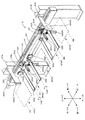
図1は、本発明にかかる印刷装置の一実施形態を示す斜視図であり、装置内部の構成を明示するために、装置カバーを外した状態の装置構成を図示している。また、図2は図1の装置の電気的構成を示すブロック図である。この印刷装置100は、装置の左側面側より装置内部に搬入される版の下面に対して、装置の正面側より装置内部に搬入されるブランケットの上面を密着させた後で剥離することで、版の下面に形成されたパターンによりブランケット上の塗布層をパターニングしてパターン層を形成する(パターニング処理)。また、印刷装置100は、装置の右側面側より装置内部に搬入される基板の下面に対して、パターニング処理されたブランケットの上面を密着させた後で剥離することで、そのブランケットに形成されたパターン層を基板の下面に転写する(転写処理)。なお、図1および後で説明する各図では、装置各部の配置関係を明確にするために、版および基板の搬送方向を「X方向」とし、図1の右手側から左手側に向かう水平方向を「+X方向」と称し、逆方向を「−X方向」と称する。また、X方向と直交する水平方向のうち、装置の正面側を「+Y方向」と称するとともに、装置の背面側を「−Y方向」と称する。さらに、鉛直方向における上方向および下方向をそれぞれ「+Z方向」および「−Z方向」と称する。
A. Overall Configuration of Apparatus FIG. 1 is a perspective view showing an embodiment of a printing apparatus according to the present invention, and illustrates the apparatus configuration with the apparatus cover removed in order to clearly show the internal configuration of the apparatus. FIG. 2 is a block diagram showing an electrical configuration of the apparatus of FIG. This
この印刷装置100では、バネ方式の除振台11の上に本体ベース12が載置され、さらに本体ベース12上に石定盤13が取り付けられている。また、この石定盤13の上面中央に2本のアーチ状フレーム14L、14Rが互いにX方向に離間しながら立設されている。これらのアーチ状フレーム14L、14Rの(−Y)側上端部には、2本の水平プレート15が連結されて第1フレーム構造体が構成されている。また、この第1フレーム構造体により覆われるように、第2フレーム構造体が石定盤13の上面に設けられている。より詳しくは、図1に示すように、各アーチ状フレーム14L、14Rの直下位置でフレーム14L、14Rよりも小型のアーチ状フレーム16L、16Rが石定盤13に立設されている。また、X方向に延設される複数の水平プレート17が各フレーム16L、16Rで柱部位同士を接続し、またY方向に延設される複数の水平プレート17がフレーム16L、16R同士を接続している。
In this
このように構成されたフレーム構造体の間では、フレーム14L、16Lの梁部位の間、ならびにフレーム14R、16Rの梁部位の間に搬送空間が形成されており、当該搬送空間を介して版及び基板を水平姿勢に保持した状態で搬送可能となっている。本実施形態では、第2フレーム構造体の後側、つまり(−Y)側に搬送部2が設けられて版および基板をX方向に搬送可能となっている。
Between the frame structures configured as described above, a conveyance space is formed between the beam portions of the
また、第1フレーム構造体を構成する水平プレート15に対して上ステージ部3が固定されて搬送部2により搬送される版および基板の上面を吸着保持可能となっている。つまり、搬送部2の版用シャトルによって版が図1の左手側から搬送空間を介して上ステージ部3の直下位置に搬送された後、上ステージ部3の吸着プレートが下降して版を吸着保持する。逆に、版用シャトルが上ステージ部3の直下位置に位置した状態で版を吸着した吸着プレートが吸着を解除すると、版が搬送部2に移載される。こうして、搬送部2と上ステージ部3との間で、版の受渡しが行われる。
Further, the
また、基板についても版と同様にして上ステージ部3に保持される。すなわち、搬送部2の基板用シャトルによって基板が図1の右手側から搬送空間を介して上ステージ部3の直下位置に搬送された後、上ステージ部3の吸着プレートが下降して基板を吸着保持する。逆に、基板用シャトルが上ステージ部3の直下位置に位置した状態で基板を吸着した上ステージ部3の吸着プレートが吸着を解除すると、基板が搬送部2に移載される。こうして、搬送部2と上ステージ部3との間で、基板の受渡しが行われる。
The substrate is also held on the
上ステージ部3の鉛直方向の下方(以下「鉛直下方」あるいは「(−Z)方向」という)では、石定盤13の上面にアライメント部4が配置されている。そして、アライメント部4のアライメントステージ上に下ステージ部5が載置されて下ステージ部5の上面が上ステージ部3の吸着プレートと対向している。この下ステージ部5の上面はブランケットを吸着保持可能となっており、制御部6がアライメントステージを制御することで下ステージ部5上のブランケットを高精度に位置決め可能となっている。
Below the
このように、本実施形態では、上ステージ部3と下ステージ部5とが鉛直方向Zにおいて互いに対向配置されている。そして、それらの間に、下ステージ部5上に載置されるブランケットを上方より押さえる押さえ部7と、版、基板およびブランケットのプリアライメントを行うプリアライメント部8とがそれぞれ配置され、第2フレーム構造体に固定されている。
Thus, in the present embodiment, the
プリアライメント部8では、プリアライメント上部およびプリアライメント下部が鉛直方向Zに2段で積層配置されている。このプリアライメント上部は上ステージ部3の吸着プレートの直下位置に位置決めされた版用シャトルに保持される版にアクセスして版用シャトル上で版の位置合せを行う(版のプリアライメント処理)。また、吸着プレートの直下位置に位置決めされた基板用シャトルに保持される基板SBにアクセスして基板用シャトル上で基板の位置合せを行う(基板のプリアライメント処理)。さらに、プリアライメント下部は下ステージ部5の吸着プレート上に載置されたブランケットにアクセスして当該吸着プレート上でブランケットの位置合せを行う(ブランケットのプリアライメント処理)。
In the
ブランケット上のパターン層を基板に精密に転写するためには、基板のプリアライメント処理以外に、精密なアライメント処理が必要となる。このため、本実施形態では、アライメント部4は4台のCCD(Charge Coupled Device)カメラCMa〜CMdを有しており、各CCDカメラCMa〜CMdにより上ステージ部3に保持される基板と、下ステージ部5に保持されるブランケットとの各々に形成されるアライメントマークを読み取り可能となっている。そして、CCDカメラCMa〜CMdによる読取画像に基づいて制御部6がアライメントステージを制御することで、上ステージ部3で保持される基板に対し、下ステージ部5で吸着されるブランケットを精密に位置合せすることが可能となっている。
In order to precisely transfer the pattern layer on the blanket to the substrate, a precise alignment process is required in addition to the pre-alignment process of the substrate. For this reason, in the present embodiment, the
また、ブランケット上のパターン層を基板に転写した後、ブランケットを基板から剥離するが、その剥離段階で静電気が発生する。また、版によりブランケット上の塗布層をパターニングした後、ブランケットを版から剥離した際にも、静電気が発生する。そこで、本実施形態では、静電気を除電するために、除電部9が設けられている。この除電部9は、第1フレーム構造体の左側、つまり(+X)側より上ステージ部3と下ステージ部5で挟まれた空間に向けてイオンを照射するイオナイザ91を有している。
Further, after transferring the pattern layer on the blanket to the substrate, the blanket is peeled off from the substrate, and static electricity is generated in the peeling step. Static electricity is also generated when the blanket is peeled off the plate after the coating layer on the blanket is patterned by the plate. Therefore, in the present embodiment, a
なお、図1への図示を省略しているが、装置カバーのうち(+X)側カバーには版を搬入出するための開口が設けられるとともに、版用開口を開閉する版用シャッター(後の図13中の符号18)が設けられている。そして、制御部6のバルブ制御部64が版用シャッター駆動シリンダCL11に接続されるバルブの開閉を切り替えることで、版用シャッター駆動シリンダCL11を作動させて版用シャッターを開閉駆動する。なお、この実施形態では、シリンダCL11を駆動するための駆動源として加圧エアーを用いており、その正圧供給源として工場の用力を用いているが、装置100がエアー供給部を装備し、当該エアー供給部によりシリンダCL11を駆動するように構成してもよい。この点については、後で説明するシリンダについても同様である。
Although not shown in FIG. 1, the (+ X) side cover of the apparatus cover is provided with an opening for loading and unloading the plate, and a plate shutter for opening and closing the plate opening (later Reference numeral 18) in FIG. 13 is provided. The
また、本実施形態では、(−X)側カバーおよび(+Y)側カバーにも、それぞれ基板およびブランケットを搬入出するための開口が設けられるとともに、基板用開口に対して基板用シャッター(後の図13中の符号19)およびブランケット用開口に対してブランケット用シャッター(図示省略)がそれぞれ設けられている。そして、バルブ制御部64によるバルブ開閉により基板用シャッター駆動シリンダCL12およびブランケット用シャッター駆動シリンダCL13がそれぞれ開閉駆動される。
In the present embodiment, the (−X) side cover and the (+ Y) side cover are also provided with openings for loading and unloading the substrate and the blanket, respectively, and the substrate shutter (rear) Blanket shutters (not shown) are provided for the reference numeral 19) and the blanket opening in FIG. The substrate shutter drive cylinder CL12 and the blanket shutter drive cylinder CL13 are each opened and closed by opening and closing the valve by the
このように、本実施形態では、3つのシャッターと3つのシャッター駆動シリンダCL11〜CL13によりシャッター部10が構成されており、版、基板およびブランケットをそれぞれ独立して印刷装置100に対して搬入出可能となっている。なお、本実施形態では、図1への図示を省略しているが、版の搬入出のために版用搬入出ユニットが装置100の左手側に並設されるとともに、基板の搬入出のために基板用搬入出ユニットが装置100の右手側に並設されているが、版を搬送するための搬送ロボット(図示省略)が直接的に搬送部2の版用シャトルにアクセスして版の搬入出を行うように構成してもよく、この場合、版用搬入出ユニットの設置は不要となる。この点に関しては、基板側でも同様である。つまり、基板を搬送するための搬送ロボット(図示省略)が直接的に搬送部2の基板用シャトルにアクセスして基板の搬入出を行うように構成することで、基板用搬入出ユニットの設置は不要となる。
As described above, in this embodiment, the shutter unit 10 is configured by the three shutters and the three shutter drive cylinders CL11 to CL13, and the plate, the substrate, and the blanket can be carried into and out of the
一方、本実施形態では、ブランケットの搬入出については、ブランケットを搬送するための搬送ロボットを用いて行っている。すなわち、当該搬送ロボットが下ステージ部5に対してアクセスして処理前のブランケットを直接的に搬入し、また使用後のブランケットを受け取り搬出する。もちろん、版や基板と同様に、専用の搬入出ユニットを装置正面側に配置してもよいことは言うまでもない。
On the other hand, in this embodiment, carrying in / out of the blanket is performed using a transfer robot for transferring the blanket. That is, the transfer robot accesses the
B.装置各部の構成
B−1.搬送部2
図3は図1の印刷装置に装備される搬送部を示す斜視図である。この搬送部2は、鉛直方向Zに延設された2本のブラケット21L、21Rを有している。図1に示すように、ブラケット21Lは左側フレーム14Lの後側柱部位の左隣で石定盤13の上面より立設され、ブラケット21Rは右側フレーム14Rの後側柱部位の右隣で石定盤13の上面より立設されている。そして、図3に示すように、これら2本のブラケット21L、21Rの上端部を互いに連結するようにボールねじ機構22が左右方向、つまりX方向に延設されている。このボールねじ機構22においては、ボールねじ(図示省略)がX方向に延びており、その一方端には、シャトル水平駆動用のモータM21の回転軸(図示省略)が連結されている。また、ボールねじの中央部に対して2つのボールねじブラケット23、23が螺合されるとともに、それらのボールねじブラケット23、23の(+Y)側面に対してX方向に延設されたシャトル保持プレート24が取り付けられている。
B. Configuration of each part of apparatus B-1.
FIG. 3 is a perspective view showing a transport unit equipped in the printing apparatus of FIG. The
このシャトル保持プレート24の(+X)側端部に版用シャトル25Lが鉛直方向Zに昇降可能に設けられる一方、(−X)側端部に基板用シャトル25Rが鉛直方向Zに昇降可能に設けられている。これらのシャトル25L、25Rは、ハンドの回転機構を除き、同一構成を有しているため、ここでは、版用シャトル25Lの構成を説明し、基板用シャトル25Rについては同一符号または相当符号を付して構成説明を省略する。
A
シャトル25Lは、X方向に版PPの幅サイズ(X方向サイズ)と同程度、あるいは若干長く延びる昇降プレート251と、昇降プレート251の(+X)側端部および(−X)側端部からそれぞれ前側、つまり(+Y)側に延設された2つの版用ハンド252、252とを有している。昇降プレート251はボールねじ機構253を介してシャトル保持プレート24の(+X)側端部に昇降可能に取り付けられている。すなわち、シャトル保持プレート24の(+X)側端部に対し、ボールねじ機構253が鉛直方向Zに延設されている。このボールねじ機構253の下端には、版用シャトル昇降モータM22Lに回転軸(図示省略)が連結されている。また、ボールねじ機構253に対してボールねじブラケット(図示省略)が螺合されるとともに、そのボールねじブラケットの(+Y)側面に対して昇降プレート251が取り付けられている。このため、制御部6のモータ制御部63からの動作指令に応じて版用シャトル昇降モータM22Lが作動することで、昇降プレート251が鉛直方向Zに昇降駆動される。
The
各ハンド252、252の前後サイズ(Y方向サイズ)は版PPの長さサイズ(Y方向サイズ)よりも長く、各ハンド252、252の先端側(+Y側)で版PPを保持可能となっている。
The front and rear size (Y direction size) of each
また、こうして版用ハンド252、252で版PPが保持されたことを検知するために、昇降プレート251の中央部から(+Y)側にセンサブラケット254が延設されるとともに、センサブラケット254の先端部に版検知用のセンサSN21が取り付けられている。このため、両ハンド252上に版PPが載置されると、センサSN21が版PPの後端部、つまり(−Y)側端部を検知し、検知信号を制御部6に出力する。
Further, in order to detect that the plate PP is held by the plate hands 252 and 252 in this way, a
さらに、各版用ハンド252、252はベアリング(図示省略)を介して昇降プレート251に取り付けられ、前後方向(Y方向)に延びる回転軸YA2を回転中心として回転自在となっている。また、昇降プレート251のX方向両端には、回転アクチュエータRA2、RA2が取り付けられている。これらの回転アクチュエータRA2、RA2は加圧エアーを駆動源として動作するものであり、加圧エアーの供給経路に介挿されたバルブ(図示省略)の開閉により180゜単位で回転可能となっている。このため、制御部6のバルブ制御部64による上記バルブの開閉を制御することで、版用ハンド252、252の一方主面が上方に向いてパターニング前の版PPを扱うのに適したハンド姿勢(以下「未使用姿勢」という)と、他方主面が上方を向いてパターニング後の版PPを扱うのに適したハンド姿勢(以下「使用済姿勢」という)との間で、ハンド姿勢を切替え可能となっている。このようにハンド姿勢の切替え機構を有している点が、版用シャトル25Lが基板用シャトル25Rと唯一相違する点である。
Furthermore, the plate hands 252 and 252 are attached to the elevating
次に、シャトル保持プレート24に対する版用シャトル25Lおよび基板用シャトル25Rの取り付け位置について説明する。この実施形態では、図3に示すように、版用シャトル25Lおよび基板用シャトル25Rは、版PPや基板SBの幅サイズ(なお実施形態では、版PPと基板SBの幅サイズは同一である)よりも長い間隔だけX方向に離間してシャトル保持プレート24に取り付けられている。そして、シャトル水平駆動モータM21の回転軸を所定方向に回転させると、両シャトル25L、25Rは上記離間距離を保ったままX方向に移動する。例えば図3では、符号XP23が上ステージ部3の直下位置を示しており、シャトル25L、25Rは、位置XP23からそれぞれ(+X)方向および(−X)方向に等距離(この距離を「ステップ移動単位」という)だけ離れた位置XP22、XP24に位置している。なお、本実施形態では、図3に示す状態を「中間位置状態」と称する。
Next, attachment positions of the
また、この中間位置状態からシャトル水平駆動モータM21の回転軸を所定方向に回転させてシャトル保持プレート24をステップ移動単位だけ(+X)方向に移動させると、基板用シャトル25Rが(+X)方向に移動して上ステージ部3の直下位置XP23まで移動して位置決めされる。このとき、版用シャトル25Lも一体的に(+X)方向に移動して版用搬入出ユニットに近接した位置XP21に位置決めされる。
Further, when the rotary shaft of the shuttle horizontal drive motor M21 is rotated in a predetermined direction from this intermediate position state and the
逆に、シャトル水平駆動モータM21の回転軸を所定方向と逆の方向に回転させてシャトル保持プレート24をステップ移動単位だけ(−X)方向に移動させると、版用シャトル25Lが中間位置状態から(−X)方向に移動して上ステージ部3の直下位置XP23まで移動して位置決めされる。このとき、基板用シャトル25Rも一体的に(−X)方向に移動して基板用搬入出ユニットに近接した位置XP25に位置決めされる。このように、本明細書では、X方向におけるシャトル位置として5つの位置XP21〜XP25が規定されている。つまり、版受渡し位置XP21は、版用シャトル25Lが位置決めされる3つの位置XP21〜XP23のうち最も版用搬入出ユニットに近接位置であり、版用搬入出ユニットとの間で版PPの搬入出が行われるX方向位置を意味している。この基板受渡し位置XP25は、基板用シャトル25Rが位置決めされる3つの位置XP23〜XP25のうち最も基板用搬入出ユニットに近接位置であり、基板用搬入出ユニットとの間で基板SBの搬入出が行われるX方向位置を意味している。また、位置XP23は上ステージ部3の吸着プレート37が鉛直方向Zに移動して版PPや基板SBを吸着保持するX方向位置を意味しており、版用シャトル25LがX方向位置XP23に位置している際には、当該位置XP23を「版吸着位置XP23」と称する一方、基板用シャトル25RがX方向位置XP23に位置している際には、当該位置XP23を「基板吸着位置XP23」と称する。また、このようにシャトル25L、25Rにより版PPや基板SBを搬送する鉛直方向Zでの位置、つまり高さ位置を「搬送位置」と称する。
On the contrary, when the rotary shaft of the shuttle horizontal drive motor M21 is rotated in the direction opposite to the predetermined direction and the
また、本実施形態では、パターニング時での版PPとブランケットとのギャップ量、ならびに転写時での基板SBとブランケットとのギャップ量を正確に制御するため、版PPおよび基板SBの厚みを計測する必要がある。そこで、版厚み計測センサSN22および基板厚み計測センサSN23が設けられている。 In the present embodiment, the thickness of the plate PP and the substrate SB is measured in order to accurately control the gap amount between the plate PP and the blanket during patterning and the gap amount between the substrate SB and the blanket during transfer. There is a need. Therefore, a plate thickness measurement sensor SN22 and a substrate thickness measurement sensor SN23 are provided.
より具体的には、図3に示すように、前側、(+Y)側に延設されたセンサブラケット26Lが左側ブラケット21Lに取り付けられてセンサブラケット26Lの先端部が位置XP21に位置決めされる版PPの上方まで延びている。そして、センサブラケット26Lの先端部に対し、版厚み計測センサSN22が取り付けられている。このセンサSN22は投光部と受光部とを有しており、版PPの上面で反射された光に基づいてセンサSN22から版PPの上面までの距離を計測するとともに、版PPの下面で反射された光に基づいてセンサSN22から版PPの下面までの距離を計測し、それらの距離に関する情報を制御部6に出力している。したがって、制御部6では、これらの距離情報から版PPの厚みを正確に求めることが可能となっている。
More specifically, as shown in FIG. 3, a plate PP in which a
また、基板側についても版側と同様にして、基板厚み計測センサSN23が設けられている。すなわち、センサブラケット26Rが右側ブラケット21Rに取り付けられてセンサブラケット26Rの先端部が位置XP25に位置決めされる基板SBの上方まで延びている。そして、センサブラケット26Rの先端部に対し、基板厚み計測センサSN23が取り付けられ、基板SBの厚みが計測される。
Further, the substrate thickness measurement sensor SN23 is provided on the substrate side as in the plate side. That is, the
B−2.上ステージ部3
図4は図1の印刷装置に装備される上ステージ部を示す斜視図である。この上ステージ部3は位置XP23(図3参照)に位置決めされる版PPや基板SBの上方に配置されており、支持フレーム31が水平プレート15と連結されることによって第1フレーム構造体に支持されている。この支持フレーム31は、図4に示すように、鉛直方向Zに延設されたフレーム側面を有しており、鉛直方向Zに延設されたボールねじ機構32を当該フレーム側面で支持している。また、ボールねじ機構32の上端部には、第1ステージ昇降モータM31の回転軸(図示省略)が連結されるとともに、ボールねじ機構32に対してボールねじブラケット321が螺合している。
B-2.
FIG. 4 is a perspective view showing an upper stage unit equipped in the printing apparatus of FIG. The
このボールねじブラケット321には、別の支持フレーム33が固定されており、ボールねじブラケット321と一体的に鉛直方向Zに昇降可能となっている。さらに、当該支持フレーム33のフレーム面で、別のボールねじ機構34が支持されている。このボールねじ機構34には、上記ボールねじ機構32のボールねじよりも狭ピッチのボールねじが設けられ、その上端部には、第2ステージ昇降モータM32の回転軸(図示省略)が連結されるとともに、中央部にはボールねじブラケット341が螺合している。
Another
このボールねじブラケット341には、ステージホルダ35が取り付けられている。ステージホルダ35は、鉛直方向Zに延設された3枚の鉛直プレート351〜353で構成されている。そのうちの鉛直プレート351はボールねじブラケット341に固着され、残りの鉛直プレート352、353はそれぞれ鉛直プレート351の左右側に固着されている。そして、鉛直プレート351〜353の鉛直下方端に対して水平支持プレート36が取り付けられ、さらに当該水平支持プレート36の下面に、例えばアルミニウム合金などの金属製の吸着プレート37が取り付けられている。
A
したがって、制御部6のモータ制御部63からの動作指令に応じてステージ昇降モータM31、M32が作動することで、吸着プレート37が鉛直方向Zに昇降移動させられる。また、本実施形態では、異なるピッチを有するボールねじ機構32、34を組み合わせ、第1ステージ昇降モータM31を作動させることで比較的広いピッチで吸着プレート37を昇降させる、つまり吸着プレート37を高速移動させることができるとともに、第2ステージ昇降モータM32を作動させることで比較的狭いピッチで吸着プレート37を昇降させる、つまり吸着プレート37を精密に位置決めすることができる。
Therefore, the
この吸着プレート37の下面、つまり版PPや基板SBを吸着保持する吸着面に複数本の吸着溝371が設けられている。また、吸着プレート37の外周縁に設けた複数の切欠部373および吸着プレート37の中央部には、複数の吸着パッド38が配置されている。なお、吸着パッド38は、先端面が吸着プレート37の下面と面一になった状態で吸着パッド38を支持するノズル本体が水平支持プレート36やノズル支持プレート39等の支持部材で支持されている。また、吸着パッド38のうち吸着プレート37の中央部に配置されるもの(図示省略)は、吸着強度を向上させるための補助的なものであり、このような補助的な吸着パッドを設けないことも可能である。
A plurality of
このように、本実施形態では、版PPや基板SBを吸着保持するための吸着手段として、吸着溝371および吸着パッド38が設けられるとともに、それぞれに対して負圧を独立して供給するための負圧供給経路を介して負圧供給源に接続されている。そして、制御部6のバルブ制御部64からの開閉指令に応じて吸着溝用の負圧供給経路に介挿されるバルブV31(図2)を開閉制御することで吸着溝371による版PPや基板SBの吸着が可能となる。また、バルブ制御部64からの開閉指令に応じて吸着パッド用の負圧供給経路に介挿されるバルブV32(図2)を開閉制御することで吸着パッド38による版PPや基板SBの吸着が可能となる。なお、本実施形態では、上記した吸着手段および後述するようにブランケットを吸着保持する吸着手段は、負圧供給源として工場の用力を用いているが、装置100が真空ポンプなどの負圧供給部を装備し、当該負圧供給部から吸着手段に負圧を供給するように構成してもよい。
As described above, in the present embodiment, the
B−3.アライメント部4
図5は図1の印刷装置に装備されるアライメント部および下ステージ部を示す斜視図である。アライメント部4および下ステージ部5は、図1に示すように、上ステージ部3の鉛直下方側に配置されている。アライメント部4は、カメラ取付ベース41、4本の柱部材42、中央部に開口が設けられた額縁状のステージ支持プレート43、アライメントステージ44および撮像部45を有している。このカメラ取付ベース41は、図1に示すように、石定盤13の上面中央部に形成された凹部の内底面に固定されている。また、カメラ取付ベース41の前後端部の各々から2本ずつ柱部材42が鉛直方向Zの上方(以下「鉛直上方」あるいは「(+Z)方向」という)に立設されており、これらによってカメラ取付ベース41のハンドリング性を向上させている。
B-3.
FIG. 5 is a perspective view showing an alignment unit and a lower stage unit equipped in the printing apparatus of FIG. As shown in FIG. 1, the
ステージ支持プレート43は、図1に示すように、石定盤13の凹部を跨ぐように水平姿勢で配置され、ステージ支持プレート43の中央開口とカメラ取付ベース41とが対向した状態で石定盤13の上面に固定されている。また、このステージ支持プレート43の上面にアライメントステージ44が固定されている。
As shown in FIG. 1, the
アライメントステージ44は、ステージ支持プレート43上に固定されるステージベース441と、ステージベース441の鉛直上方に配置されて下ステージ部5を支持するステージトップ442とを有している。これらステージベース441およびステージトップ442はいずれも中央部に開口を有する額縁形状を有している。また、これらステージベース441およびステージトップ442の間には、鉛直方向Zに延びる回転軸を回転中心とする回転方向、X方向およびY方向の3自由度を有する、例えばクロスローラベアリング等の支持機構(図示省略)がステージトップ442の各角部近傍に配置されている。
The
これらの支持機構のうち、前左角部に配置される支持機構に対してY軸ボールねじ機構443aが設けられるとともに、当該Y軸ボールねじ機構443aにY軸駆動モータM41が取り付けられている。また、前右角部に配置される支持機構に対してX軸ボールねじ機構443bが設けられるとともに、当該X軸ボールねじ機構443bにX軸駆動モータM42が取り付けられている。また、後右角部に配置される支持機構に対してY軸ボールねじ機構443cが設けられるとともに、当該Y軸ボールねじ機構443cの駆動源としてY軸駆動モータM43が取り付けられている。さらに、後左角部に配置される支持機構に対してX軸ボールねじ機構(図示省略)が設けられるとともに、当該X軸ボールねじ機構にX軸駆動モータM44(図2)が取り付けられている。このため、制御部6のモータ制御部63からの動作指令に応じて各駆動モータM41〜M44を作動させることで、アライメントステージ44の中央部に比較的大きな空間を設けながら、ステージトップ442を水平面内で移動させるとともに、鉛直軸を回転中心として回転させて下ステージ部5の吸着プレートを位置決め可能となっている。
Among these support mechanisms, a Y-axis
本実施形態において中空空間を有するアライメントステージ44を用いた理由のひとつは、下ステージ部5の上面に保持されるブランケットおよび上ステージ部3の下面に保持される基板SBに形成されるアライメントマークを撮像部45により撮像するためである。以下、図5および図6を参照しつつ撮像部45の構成について説明する。
One of the reasons for using the
図6はアライメント部の撮像部を示す斜視図である。撮像部45は、ブランケットの4箇所にそれぞれ形成されるアライメントマーク、ならびに基板SBの4箇所にそれぞれ形成されるアライメントマークを撮像するものであり、4つの撮像ユニット45a〜45dを有している。各撮像ユニット45a〜45dの撮像対象領域は、
撮像ユニット45a:ブランケットおよび基板SBの前左角部の近傍領域、
撮像ユニット45b:ブランケットおよび基板SBの前右角部の近傍領域、
撮像ユニット45c:ブランケットおよび基板SBの後右角部の近傍領域、
撮像ユニット45d:ブランケットおよび基板SBの後左角部の近傍領域、
であり、互いに異なっているが、ユニット構成は同一である。したがって、ここでは、撮像ユニット45aの構成を説明し、その他の構成については同一または相当符号を付して説明を省略する。
FIG. 6 is a perspective view showing an imaging unit of the alignment unit. The
Although they are different from each other, the unit configuration is the same. Therefore, here, the configuration of the
撮像ユニット45aでは、XYテーブル451が、図6に示すように、カメラ取付ベース41の前左角部の近傍上面に配置されている。このXYテーブル451のテーブルベースがカメラ取付ベース41に固定されており、調整つまみ(図示省略)をマニュアルで操作することでXYテーブル451のテーブルトップがX方向およびY方向に精密に位置決めされる。このテーブルトップ上に、精密昇降テーブル452が取り付けられている。この精密昇降テーブル452には、Z軸駆動モータM45a(図2)が設けられており、制御部6のモータ制御部63からの動作指令に応じてZ軸駆動モータM45aが作動することで精密昇降テーブル452のテーブルトップが鉛直方向Zに昇降移動する。
In the
この精密昇降テーブル452のテーブルトップの上面には、鉛直方向Zに延設されたカメラブラケット453の下端部が固定される一方、上端部がステージ支持プレート43の中央開口、アライメントステージ44の中央開口およびステージベースの長孔開口(これについては後で詳述する)を通過して下ステージ部5の吸着プレート51の直下近傍まで延設されている。そして、このカメラブラケット453の上端部に対し、撮像面を鉛直上方側に向けた状態でCCDカメラCMa、鏡筒454および対物レンズ455がこの順序で積層配置されている。また、鏡筒454の側面には光源456が取り付けられており、光源駆動部46により点灯駆動される。本実施形態では、光源456としては赤色LED(Light Emitting Diode)を用いているが、ブランケットや基板SBの材質などに応じた光源を用いることができる。また、鏡筒454の上方には対物レンズ455が取り付けられている。さらに、鏡筒454の内部には、ハーフミラー(図示省略)が配置されており、光源456から射出された照明光を(+Z)方向に折り曲げ、対物レンズ455および吸着プレート51の前左角部の近傍領域に設けられた石英窓52aを介して下ステージ部5上のブランケットに照射する。また、照明光の一部はさらに当該ブランケットを介して上ステージ部3の吸着プレート37に吸着保持される基板SBに照射する。なお、本実施形態では、ブランケットは透明部材で構成されているため、上記したように照明光はブランケットを透過して基板SBの下面に到達する。
The lower end of a
また、ブランケットや基板SBから射出される光のうち(−Z)側に進む光は、石英窓52a、対物レンズ455および鏡筒454を介してCCDカメラCMaに入射し、CCDカメラCMaが石英窓52aの鉛直上方に位置するアライメントマークを撮像する。このように撮像ユニット45aでは、石英窓52aを介して照明光を照射するとともに石英窓52aを介してブランケットおよび基板SBの前左角部の近傍領域の画像を撮像し、その像に対応する画像信号を制御部6の画像処理部65に出力する。一方、他の撮像ユニット45b〜45dは、撮像ユニット45aと同様にして、それぞれ石英窓52b〜52dを介して画像を撮像する。
Of the light emitted from the blanket or the substrate SB, the light traveling to the (−Z) side is incident on the CCD camera CMa via the
B−4.下ステージ部5
次に、図5に戻って下ステージ部5の構成について詳述する。この下ステージ部5は、吸着プレート51と、上記した4つの石英窓52a〜52dと、4本の柱部材53と、ステージベース54と、リフトピン部55とを有している。ステージベース54には、左右方向Xに延びる長孔形状の開口が前後方向Yに3つ並んで設けられている。そして、これらの長孔開口と、アライメントステージ44の中央開口とが上方からの平面視でオーバーラップするように、ステージベース54がアライメントステージ44上に固定されている。また、前側の長孔開口には、撮像ユニット45a、45bの上方部(CCDカメラ、鏡筒および対物レンズ)が遊挿されるとともに、後側の長孔開口には、撮像ユニット45c、45dの上方部(CCDカメラ、鏡筒および対物レンズ)が遊挿されている。また、ステージベース54の上面角部から柱部材53が(+Z)に立設され、各頂部が吸着プレート51を支持している。
B-4.
Next, returning to FIG. 5, the configuration of the
この吸着プレート51は例えばアルミニウム合金などの金属プレートであり、その前左角部、前右角部、後右角部および後左角部の近傍領域には、石英窓52a〜52dがそれぞれ設けられている。また、吸着プレート51の上面には、石英窓52a〜52dを取り囲むように溝511が設けられるとともに、溝511により囲まれる内部領域では、石英窓52a〜52dを除き、左右方向Xに延びる複数の溝512が前後方向Yに一定間隔で設けられている。
The
これら溝511、512の各々に対して正圧供給配管(図示省略)の一方端が接続されるとともに、他方端が加圧用マニホールドに接続されている。さらに、各正圧供給配管の中間部に加圧バルブV51(図2)が介挿されている。この加圧用マニホールドに対しては、工場の用力から供給される加圧エアーをレギュレータで調圧することで得られる一定圧力のエアーが常時供給されている。このため、制御部6のバルブ制御部64からの動作指令に応じて所望の加圧バルブV51が選択的に開くと、その選択された加圧バルブV51に繋がる溝511、512に対して調圧された加圧エアーが供給される。
One end of a positive pressure supply pipe (not shown) is connected to each of the
また、溝511、512の各々に対しては、加圧エアーの選択供給のみならず、選択的な負圧供給も可能となっている。すなわち、溝511、512の各々に対して負圧供給配管(図示省略)の一方端が接続されるとともに、他方端が負圧用マニホールドに接続されている。さらに、各負圧供給配管の中間部に吸着バルブV52(図2)が介挿されている。この負圧用マニホールドには、負圧供給源がレギュレータを介して接続されており、所定値の負圧が常時供給されている。このため、制御部6のバルブ制御部64からの動作指令に応じて所望の吸着バルブV52が選択的に開くと、その選択された吸着バルブV52に繋がる溝511、512に対して調圧された負圧が供給される。
Further, not only selective supply of pressurized air but also selective negative pressure supply is possible for each of the
このように本実施形態では、バルブV51、52の開閉制御によって吸着プレート51上にブランケットを部分的あるいは全面的に吸着させたり、吸着プレート51とブランケットとの間にエアーを部分的に供給してブランケットを部分的に膨らませて上ステージ部3に保持された版PPや基板SBに押し遣ることが可能となっている。
As described above, in this embodiment, the blanket is partially or completely adsorbed on the
図7は下ステージ部に装備されるリフトピン部を示す図であり、同図(a)はリフトピン部の平面図であり、同図(b)は側面図である。リフトピン部55では、リフトプレート551が吸着プレート51とステージベース54との間で昇降自在に設けられている。このリフトプレート551には、4箇所の切欠部551a〜551dが形成されて撮像ユニット45a〜45dとの干渉が防止されている。つまり、撮像ユニット45a〜45dがそれぞれ切欠部551a〜551dに入り込む状態で、リフトプレート551は鉛直方向Zに昇降可能となっている。また、このように4箇所の切欠部551a〜551dを設けることでリフトプレート551には6本のフィンガー部551e〜551jが形成され、各フィンガー部551e〜551jの先端部から鉛直上方にリフトピン552e〜552jがそれぞれ立設されている。また、リフトピン552e、552fの間に別のリフトピン552kが立設されるとともに、リフトピン552i、552jの間にさらに別のリフトピン552mが立設されており、合計8本のリフトピン552(552e〜552k、552m)がリフトプレート551に立設されてブランケットの下面全体を支持可能となっている。これらのリフトピン552は吸着プレート51の外周縁に対して鉛直方向Zに穿設された貫通孔(図示省略)よりも細く、図5に示すように、貫通孔を鉛直下方側より挿通可能となっている。
FIG. 7 is a view showing a lift pin portion mounted on the lower stage portion. FIG. 7 (a) is a plan view of the lift pin portion, and FIG. 7 (b) is a side view. In the
また、各リフトピン552の上端側から圧縮ばね553およびハウジング554がこの順序で外挿され、圧縮ばね553の下端部がリフトプレート551で係止されるとともに、その上端部に対してハウジング554が覆い被さっている。なお、ハウジング554の上面は、吸着プレート51の貫通孔の内径よりも大きな外径を有する円形形状を有しており、次に説明するようにピン昇降シリンダCL51によりリフトプレート551を上昇させた際、ハウジング554の上面は吸着プレート51の下面で係止され、リフトプレート551とで圧縮ばね553を挟み込んで収縮させてリフトプレート551の上昇速度をコントロールする。また、リフトプレート551の下降にも、圧縮ばね553の圧縮力を利用してリフトプレート551の下降速度をコントロールする。
Further, the
このピン昇降シリンダCL51は、下面がカメラ取付ベース41に固定されたガイドブラケット555の側面に固定されており、ピン昇降シリンダCL51のピストン先端がスライドブロック556を介してリフトプレート551を支持している。したがって、制御部6のバルブ制御部64がピン昇降シリンダCL51に接続されるバルブの開閉を切り替えることで、ピン昇降シリンダCL51を作動させてリフトプレート551を昇降させる。その結果、吸着プレート51の上面、つまり吸着面に対し、全リフトピン552が進退移動させられる。例えば、リフトピン552が吸着プレート51の上面から(+Z)方向に突出することで、ブランケット搬送ロボットによりブランケットがリフトピン552の頂部に載置可能となる。そして、ブランケットの載置に続いて、リフトピン552が吸着プレート51の上面よりも(−Z)方向に後退することで、ブランケットが吸着プレート51の上面に移載される。その後、後述するように適当なタイミングで、吸着プレート51の近傍に配置されたブランケット厚み計測センサSN51によって当該ブランケットの厚みが計測される。
The pin elevating cylinder CL51 is fixed to the side surface of a
図8はブランケット厚み計測部を示す斜視図である。この実施形態では、ブランケット厚み計測部56は下ステージ部5の一部構成であり、次のように構成されている。ブランケット厚み計測部56では、シリンダブラケット561が吸着プレート51の右側近傍位置で第2フレーム構造体に固定されている。また、このシリンダブラケット561に対し、センサ水平駆動シリンダCL52が水平状態で固定されており、制御部6のバルブ制御部64が当該シリンダCL52に接続されるバルブの開閉を切り替えることで、シリンダCL52に取り付けられたスライドプレート562が左右方向Xにスライドする。このスライドプレート562の左端部にはブランケット厚み計測センサSN51が取り付けられている。このため、センサ水平駆動シリンダCL52によってスライドプレート562が左(+X)側、つまり吸着プレート51側に水平移動すると、ブランケット厚み計測センサSN51が吸着プレート51に吸着保持されるブランケットの右端部の直上位置に位置決めされる。このセンサSN51も、版厚み計測センサSN22および基板厚み計測センサSN23と同様に構成されており、同様の計測原理によりブランケットの厚みを計測可能となっている。一方、計測以外のタイミングにおいては、センサ水平駆動シリンダCL52によってスライドプレート562は右(−X)側、つまり吸着プレート51から離れた退避位置に移動させられており、ブランケット厚み計測部56の干渉が防止される。
FIG. 8 is a perspective view showing a blanket thickness measurement unit. In this embodiment, the blanket
B−5.押さえ部7
図9は図1の印刷装置に装備される押さえ部を示す図である。同図(a)は押さえ部7の構成を示す斜視図であり、同図(b)は吸着プレート51に吸着保持されるブランケットBLを押さえ部7により押さえた状態(以下「ブランケット押さえ状態」という)を示し、同図(c)は押さえ部7によるブランケットBLを解除した状態(以下「ブランケット押さえ解除状態」という)を示している。この押さえ部7は、吸着プレート51の鉛直上方側に設けられる押さえ部材71を切替機構72によって鉛直方向Zに昇降することでブランケット押さえ状態とブランケット押さえ解除状態とを切り替える。
B-5. Holding
FIG. 9 is a diagram illustrating a pressing unit provided in the printing apparatus of FIG. FIG. 4A is a perspective view showing the configuration of the
この切替機構72では、第2フレーム構造体の水平プレート17に対し、それぞれシリンダブラケット721〜723によって押さえ部材昇降シリンダCL71〜CL73が、ピストン724を鉛直下方側に進退自在に、取り付けられている。これらのピストン724の先端部では、押さえ部材71がぶら下がり状態で遊嵌されている。
In the
押さえ部材71は、支持プレート711と、4つのブランケット押さえプレート712とを有している。支持プレート711は、ブランケットBLと同一の平面サイズを有し、その中央部が開口しており、全体として額縁形状を有している。この支持プレート711の下面に対し、4枚のブランケット押さえプレート712が固定されて支持プレート711の下面全部を覆っている。
The pressing
また、支持プレート711には、図9(b)、(c)に示すように、押さえ部材昇降シリンダCL71〜CL73に対応する位置にピストン724の外径よりも広い内径を有する貫通孔716が穿設されている。そして、各貫通孔716の下方側より締結部材717が貫通孔716を介してピストン724の先端部に接続されている。これによって、押さえ部材昇降シリンダCL71〜CL73のピストン724は支持プレート711に遊嵌された状態で押さえ部材昇降シリンダCL71〜CL73に連結される。つまり、押さえ部材71は押さえ部材昇降シリンダCL71〜CL73に対してフローティング状態で支持されている。
Further, as shown in FIGS. 9B and 9C, the
そして、制御部6のバルブ制御部64が押さえ部材昇降シリンダCL71〜CL73に接続されるバルブの開閉を切り替えることで、押さえ部材昇降シリンダCL71〜CL73を作動させて押さえ部材71を下ステージ部5の吸着プレート51に対して当接または離間させる。例えば、押さえ部材71がブランケットBLを保持している吸着プレート51に下降してブランケット押さえ状態となり、ブランケットBLの周縁部を全周にわたって吸着プレート51とで挟み込んでホールドする。また、アライメントのために吸着プレート51が移動した際にも、押さえ部材71は吸着プレート51とともに水平方向(X方向、Y方向)に移動し、ブランケットBLを安定して保持する。
And the
B−6.プリアライメント部8
図10は図1の印刷装置に装備されるプリアライメント部を示す斜視図である。プリアライメント部8は、プリアライメント上部81と、プリアライメント下部82とを有している。これらのうちプリアライメント上部81は、プリアライメント下部82よりも鉛直上方側に配置され、ブランケットBLとの密着に先立って、位置XP23で版用シャトル25Lにより保持される版PPおよび基板用シャトル25Rにより保持される基板SBをアライメントする。一方、プリアライメント下部82は、版PPや基板SBとの密着に先立って、下ステージ部5の吸着プレート51に載置されるブランケットBLをアライメントする。なお、プリアライメント上部81と、プリアライメント下部82とは基本的に同一構成を有している。そこで、以下においては、プリアライメント上部81の構成について説明し、プリアライメント下部82については同一または相当符号を付して構成説明を省略する。
B-6.
FIG. 10 is a perspective view showing a pre-alignment unit equipped in the printing apparatus of FIG. The
プリアライメント上部81は、4つの上ガイド移動部811〜814を有している。各上ガイド移動部811〜814は第2フレーム構造体を構成する複数の水平プレートのうち上段側に配置された水平プレート17に設けられている。すなわち、前後方向Yに延設された2本の水平プレートのうちの左側水平プレート17aに対し、その中央部に上ガイド移動部811が取り付けられるとともに、その前側端部に上ガイド移動部812が取り付けられている。また、もう一方の右側水平プレート17bに対し、その中央部に上ガイド移動部813が取り付けられるとともに、その後側端部に上ガイド移動部814が取り付けられている。なお、上ガイド移動部811、813は同一構成を有し、また上ガイド移動部812、814は同一構成を有している。したがって、以下においては、上ガイド移動部811、812の構成を詳述し、上ガイド移動部813、814について同一または相当符号を付して構成説明を省略する。
The pre-alignment
上ガイド移動部811では、ボールねじ機構811aが左右方向Xに延設された状態で左側水平プレート17aの中央部に固定されている。そして、ボールねじ機構811aのボールねじに対してボールねじブラケットが螺合されるとともに、当該ボールねじブラケットに上ガイド811bが上ガイド移動部813に対向して取り付けられている。また、ボールねじ機構811aの左端部に上ガイド駆動モータM81aの回転軸(図示省略)が連結されており、制御部6のモータ制御部63からの動作指令に応じて上ガイド駆動モータM81aが作動することで上ガイド811bが左右方向Xに移動する。
In the upper
また、上ガイド移動部812では、ボールねじ機構812aが前後方向Yに延設された状態で左側水平プレート17aの前側端部に固定されている。そして、ボールねじ機構812aのボールねじに対してボールねじブラケットが螺合されるとともに、当該ボールねじブラケットに対し、左右方向に延設されたガイドホルダ812cの左端部が固定されている。このガイドホルダ812cの右端部は、水平プレート17a、17bの中間位置に達しており、その右端部に上ガイド812bが上ガイド移動部814に対向して取り付けられている。また、ボールねじ機構812aの後端部に上ガイド駆動モータM81bの回転軸(図示省略)が連結されており、制御部6のモータ制御部63からの動作指令に応じて上ガイド駆動モータM81bが作動することで上ガイド812bが前後方向Yに移動する。
Further, in the upper
このように4つの上ガイド811b〜814bが位置XP23の鉛直下方位置で版PPや基板SB(同図中の一点鎖線)を取り囲んでおり、各上ガイド811b〜814bが独立して版PPなどに対して近接および離間可能となっている。したがって、各上ガイド811b〜814bの移動量を制御することによって版PPおよび基板SBをシャトルのハンド上で水平移動あるいは回転させてアライメントすることが可能となっている。
As described above, the four
B−7.除電部9
図11は図1の印刷装置に装備される除電部を示す斜視図である。除電部9では、ベースプレート92が下ステージ部5の左側で石定盤13の上面に固定されている。また、ベースプレート92から柱部材93が立設されており、その上端部は下ステージ部5よりも高い位置まで延設されている。そして、ベースプレート92の上端部に対して固定金具94を介してイオナイザブラケット95が取り付けられている。このイオナイザブラケット95は右方向(−X)に延設され、その先端部は吸着プレート51の近傍に達している。そして、その先端部にイオナイザ91が取り付けられている。
B-7.
FIG. 11 is a perspective view showing a static eliminating unit provided in the printing apparatus of FIG. In the static eliminating
B−8.制御部6
制御部6は、CPU(Central Processing Unit)61、メモリ62、モータ制御部63、バルブ制御部64、画像処理部65および表示/操作部66を有しており、CPU61はメモリ62に予め記憶されたプログラムにしたがって装置各部を制御して、図12ないし図19に示すように、パターニング処理および転写処理を実行する。
B-8.
The
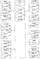
C.印刷装置の全体動作
図12は、図1の印刷装置の全体動作を示すフローチャートである。また、図13ないし図19は、図1の印刷装置の動作を説明するための図であり、図中のテーブルは制御部6による制御内容(制御対象および動作内容)を示し、また図中の模式図は装置各部の状態を示している。この印刷装置100の初期状態では、図13(a)に示すように、版用シャトル25Lおよび基板用シャトル25Rはそれぞれ中間位置XP22、XP24に位置決めされており、版用搬入出ユニットへの版PPのセットを待って版PPの投入工程(ステップS1)、ならびに基板用搬入出ユニットへの基板SBのセットを待って基板SBの投入工程(ステップS2)を実行する。なお、版用シャトル25Lおよび基板用シャトル25Rが一体的に左右方向Xに移動するという搬送構造を採用しているため、版PPの搬入を行った(ステップS1)後、基板SBの搬入を行う(ステップS2)が、両者の順序を入れ替えてもよい。
C. Overall Operation of Printing Apparatus FIG. 12 is a flowchart showing the overall operation of the printing apparatus of FIG. 13 to 19 are diagrams for explaining the operation of the printing apparatus of FIG. 1, and the table in the figure shows the control contents (control target and operation contents) by the
C−1.版搬入工程(ステップS1)
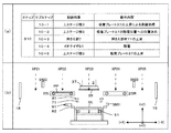
図13(b)の「ステップS1」の欄に示すように、サブステップ(1−1)〜(1−7)を実行する。すなわち、シャトル水平駆動モータM21が回転軸を所定方向に回転させ、シャトル保持プレート24を(+X)方向に移動させる(1−1)。これによって、版用シャトル25Lが版受渡し位置XP21に移動して位置決めされる。また、回転アクチュエータRA2、RA2が動作し、版用ハンド252、252を180゜回転させて原点位置に位置決めする(1−2)。これによって、ハンド姿勢が使用済姿勢から未使用姿勢に切り替わり、使用前の版PPの投入準備が完了する。
C-1. Plate loading process (step S1)
As shown in the column of “Step S1” in FIG. 13B, sub-steps (1-1) to (1-7) are executed. That is, the shuttle horizontal drive motor M21 rotates the rotation shaft in a predetermined direction and moves the
そして、版用シャッター駆動シリンダCL11が動作し、版用シャッター18を鉛直下方に移動させる、つまりシャッター18を開く(1−3)。それに続いて、制御部6からの動作指令に応じて版用搬入出ユニットが版PPを印刷装置100の内部に搬入し、版用シャトル25Lのハンド252,252上に載置する(1−4)。こうして版PPの投入が完了すると、上記バルブの開閉状態を元に戻すことで版用シャッター駆動シリンダCL11が逆方向に作動して版用シャッター18を元の位置に戻す、つまりシャッター18を閉じる(1−5)。
Then, the plate shutter drive cylinder CL11 is operated to move the
版PPの投入完了時点では、版PPは版受渡し位置XP21に位置している。そこで、このタイミングで、版厚み計測センサSN22が作動して版PPの上面および下面の高さ位置(鉛直方向Zにおける位置)を検出し、それらの検出結果を示す高さ情報を制御部6に出力する。そして、これらの高さ情報に基づいてCPU61は版PPの厚みを求め、メモリ62に記憶する。こうして、版PPの厚み計測が実行される(1−6)。その後、シャトル水平駆動モータM21が回転軸を逆回転させてシャトル保持プレート24を(−X)方向に移動させ、中間位置XP22に位置決めする(1−7)。
At the completion of loading the plate PP, the plate PP is located at the plate delivery position XP21. Therefore, at this timing, the plate thickness measurement sensor SN22 operates to detect the height positions (positions in the vertical direction Z) of the upper and lower surfaces of the plate PP, and height information indicating the detection results is sent to the
C−2.基板投入工程(ステップS2)
図13(b)の「ステップS2」の欄に示すように、サブステップ(2−1)〜(2−6)を実行する。すなわち、シャトル水平駆動モータM21が回転軸を所定方向と逆方向に回転させ、シャトル保持プレート24を(−X)方向に移動させる(2−1)。これによって、基板用シャトル25Rが基板受渡し位置XP25に移動して位置決めされる。なお、基板用ハンド252、252については回転機構が設けられておらず、サブステップ(2−1)が完了した時点で基板SBの投入準備が完了する。
C-2. Substrate loading process (step S2)
As shown in the column of “Step S2” in FIG. 13B, the sub-steps (2-1) to (2-6) are executed. That is, the shuttle horizontal drive motor M21 rotates the rotating shaft in the direction opposite to the predetermined direction, and moves the
そして、基板用シャッター駆動シリンダCL12が動作し、基板用シャッター19を鉛直下方に移動させる、つまりシャッター19を開く(2−2)。それに続いて、制御部6からの動作指令に応じて基板用搬入出ユニットが基板SBを印刷装置100の内部に搬入し、基板用シャトル25Rのハンド252,252上に載置する(2−3)。こうして基板SBの投入が完了すると、上記バルブの開閉状態を元に戻すことで基板用シャッター駆動シリンダCL12が逆方向に作動して基板用シャッター19を元の位置に戻す、つまりシャッター19を閉じる(2−4)。
Then, the substrate shutter drive cylinder CL12 operates to move the
基板SBの投入完了時点では、基板SBは基板受渡し位置XP25に位置している。そこで、このタイミングで、基板厚み計測センサSN23が作動して基板SBの上面および下面の高さ位置を検出し、それらの検出結果を示す高さ情報を制御部6に出力する。そして、これらの高さ情報に基づいてCPU61は、版PPに続いて、基板SBの厚みを求め、メモリ62に記憶する。こうして、基板SBの厚み計測が実行される(2−5)。その後、シャトル水平駆動モータM21が回転軸を所定方向に回転させてシャトル保持プレート24を(+X)方向に移動させ、中間位置XP24に位置決めする(2−6)。
When the loading of the substrate SB is completed, the substrate SB is located at the substrate delivery position XP25. Therefore, at this timing, the substrate thickness measurement sensor SN23 operates to detect the height positions of the upper surface and the lower surface of the substrate SB, and outputs height information indicating the detection results to the
このように、本実施形態では、図13(c)に示すように、パターニング処理を実行する前に、版PPのみならず、基板SBをも準備しておき、後で詳述するように、パターニング処理および転写処理を連続して実行する。これによって、ブランケットBL上でパターニングされた塗布層が基板SBに転写されるまでの時間間隔を短縮することができ、安定した処理が実行される。 Thus, in the present embodiment, as shown in FIG. 13C, before performing the patterning process, not only the plate PP but also the substrate SB is prepared, and as will be described in detail later. The patterning process and the transfer process are continuously performed. As a result, the time interval until the coating layer patterned on the blanket BL is transferred to the substrate SB can be shortened, and stable processing is performed.
C−3.版吸着(ステップS3)
図14(a)の「ステップS3」の欄に示すように、サブステップ(3−1)〜(3−7)を実行する。すなわち、シャトル水平駆動モータM21が回転軸を回転させ、シャトル保持プレート24を(−X)方向に移動させる(3−1)。これによって、版用シャトル25Lが版吸着位置XP23に移動して位置決めされる。そして、版用シャトル昇降モータM22Lが回転軸を回転させ、昇降プレート251を下方向(−Z)に移動させる(3−2)。これによって、版用シャトル25Lに支持されたまま版PPが搬送位置よりも低いプリアライメント位置に移動して位置決めされる。
C-3. Plate adsorption (step S3)
As shown in the column of “Step S3” in FIG. 14A, the sub-steps (3-1) to (3-7) are executed. That is, the shuttle horizontal drive motor M21 rotates the rotation shaft, and moves the
次に、上ガイド駆動モータM81a〜M81dが回転軸を回転させ、上ガイド811b、813bが左右方向Xに移動するとともに、上ガイド812b、814bが前後方向Yに移動し、各上ガイド811b〜814bが版用シャトル25Lに支持される版PPの端面と当接して版PPを予め設定した水平位置に位置決めする。その後、各上ガイド駆動モータM81a〜M81dが回転軸を逆方向に回転させ、各上ガイド811b〜814bが版PPから離間する(3−3)。
Next, the upper guide drive motors M81a to M81d rotate the rotation shaft, the
こうして、版PPのプリアライメント処理が完了すると、ステージ昇降モータM31が回転軸を所定方向に回転させ、吸着プレート37を下方向(−Z)に下降させて版PPの上面と当接させる。それに続いて、バルブV31,V32が開き、これによって吸着溝371および吸着パッド38により版PPが吸着プレート37に吸着される(3−4)。
Thus, when the pre-alignment processing of the plate PP is completed, the stage elevating motor M31 rotates the rotating shaft in a predetermined direction, and the
吸着検出センサSN31(図2)により版PPの吸着が検出されると、ステージ昇降モータM31が回転軸を逆方向に回転させ、吸着プレート37が版PPを吸着保持したまま鉛直上方に上昇して版吸着位置XP23の鉛直上方位置に版PPを移動させる(3−5)。そして、版用シャトル昇降モータM22Lが回転軸を回転させ、昇降プレート251を鉛直上方に移動させ、版用シャトル25Lをプリアライメント位置から搬送位置、つまり版吸着位置XP23に移動して位置決めする(3−6)。その後、シャトル水平駆動モータM21が回転軸を回転させてシャトル保持プレート24を(+X)方向に移動させ、空になった版用シャトル25Lを中間位置XP22に位置決めする(3−7)。
When the adsorption of the plate PP is detected by the adsorption detection sensor SN31 (FIG. 2), the stage elevating motor M31 rotates the rotating shaft in the reverse direction, and the
C−4.ブランケット吸着(ステップS4)
図14(a)の「ステップS4」の欄に示すように、サブステップ(4−1)〜(4−9)を実行する。すなわち、X軸駆動モータM42,M44およびY軸駆動モータM41,M43が作動してアライメントステージ44を初期位置に移動させる(4−1)。これによって、毎回スタートが同じ位置となる。それに続いて、ピン昇降シリンダCL51が動作してリフトプレート551を上昇させ、リフトピン552を吸着プレート51の上面から鉛直上方に突出させる(4−2)。こうして、ブランケットBLの投入準備が完了すると、ブランケット用シャッター駆動シリンダCL13が動作し、ブランケット用シャッター(図示省略)を移動させて当該シャッターを開く(4−3)。そして、ブランケット搬送ロボットが、装置100にアクセスしてブランケットBLをリフトピン552の頂部に載置した後、装置100から退避する(4−4)。これに続いて、ブランケット用シャッター駆動シリンダCL13が動作し、ブランケット用シャッターを移動させて当該シャッターを閉じる(4−5)。
C-4. Blanket adsorption (step S4)
As shown in the column of “Step S4” in FIG. 14A, the sub-steps (4-1) to (4-9) are executed. That is, the X-axis drive motors M42 and M44 and the Y-axis drive motors M41 and M43 are operated to move the
次に、ピン昇降シリンダCL51が動作してリフトプレート551を下降させる。これによって、リフトピン552がブランケットBLを支持したまま下降してブランケットBLを吸着プレート51に載置する(4−6)。すると、下ガイド駆動モータM82a〜M82dが回転軸を回転させ、下ガイド821b、823bが左右方向Xに移動するとともに、下ガイド822b、824bが前後方向Yに移動し、各下ガイド821b〜824bが吸着プレート51に支持されるブランケットBLの端面と当接してブランケットBLを予め設定した水平位置に位置決めする(4−7)。
Next, the pin lifting cylinder CL51 operates to lower the
こうしてブランケットBLのプリアライメント処理が完了すると、吸着バルブV52が開き、これによって溝511、512に対して調圧された負圧が供給されてブランケットBLが吸着プレート51に吸着される(4−8)。さらに、各下ガイド駆動モータM82a〜M82dが回転軸を逆方向に回転させ、各下ガイド821b〜824bをブランケットBLから離間させる(4−9)。これによって、図14(b)に示すように、パターニング処理の準備が完了する。
When the pre-alignment processing of the blanket BL is completed in this way, the suction valve V52 is opened, thereby supplying a negative pressure regulated to the
C−5.パターニング(ステップS5)
ここでは、ブランケット厚みが計測された後で、パターニングが実行される。すなわち、図15(a)の「ステップS5」の欄に示すように、センサ水平駆動シリンダCL52が動作してブランケット厚み計測センサSN51をブランケットBLの右端部の直上位置に位置決めする(5−1)。そして、ブランケット厚み計測センサSN51がブランケットBLの厚みに関連する情報を制御部6に出力し、これによってブランケットBLの厚みが計測される(5−2)。その後で、上記センサ水平駆動シリンダCL52が逆方向に動作してスライドプレート562を(−X)方向にスライドさせてブランケット厚み計測センサSN51を吸着プレート51から退避させる(5−3)。
C-5. Patterning (Step S5)
Here, patterning is performed after the blanket thickness is measured. That is, as shown in the column of “Step S5” in FIG. 15A, the sensor horizontal drive cylinder CL52 operates to position the blanket thickness measurement sensor SN51 at a position immediately above the right end of the blanket BL (5-1). . And blanket thickness measurement sensor SN51 outputs the information relevant to the thickness of blanket BL to the
次に、第1ステージ昇降モータM31が回転軸を所定方向に回転させ、吸着プレート37を下方向(−Z)に下降させて版PPをブランケットBLの近傍に移動させる。さらに、第2ステージ昇降モータM32が回転軸を回転させ、狭いピッチで吸着プレート37を昇降させて鉛直方向Zにおける版PPとブランケットBLの間隔、つまりギャップ量を正確に調整する(5−4)。なお、このギャップ量は版PPおよびブランケットBLの厚み計測結果に基づいて制御部6により決定される。
Next, the first stage elevating motor M31 rotates the rotating shaft in a predetermined direction, lowers the
そして、押さえ部材昇降シリンダCL71〜CL73が動作し、押さえ部材71を下降させてブランケットBLの周縁部を全周にわたって押さえ部材71で押さえ付ける(5−5)。それに続いて、バルブV51、52が動作して吸着プレート51とブランケットBLとの間にエアーを部分的に供給してブランケットBLを部分的に膨らませる。この浮上部分が上ステージ部3に保持された版PPに押し遣られる(5−6)。その結果、図15(b)に示すように、ブランケットBLの中央部が版PPに密着して版PPの下面に予め形成されたパターン(図示省略)がブランケットBLの上面に予め塗布された塗布層と当接して当該塗布層をパターニングしてパターン層を形成する。
Then, the pressing member elevating cylinders CL71 to CL73 operate to lower the pressing
C−6.版剥離(ステップS6)
図15(c)の「ステップS6」の欄に示すように、サブステップ(6−1)〜(6−5)を実行する。すなわち、第2ステージ昇降モータM32が回転軸を回転させて吸着プレート37が上昇して版PPをブランケットBLから剥離させる(6−1)。また、剥離処理を行うために版PPを上昇させるのと並行して適時、バルブV51、V52の開閉状態を切替え、ブランケットBLに負圧を与えて吸着プレート37側に引き寄せる。その後、第1ステージ昇降モータM31が回転軸を回転させ、吸着プレート37を上昇させて版PPをイオナイザ91とほぼ同一高さの除電位置に位置決めする(6−2)。また、押さえ部材昇降シリンダCL71〜CL73が動作し、押さえ部材71を上昇させてブランケットBLの押さえ付けを解除する(6−3)。それに続いて、イオナイザ91が作動して上記版剥離処理時に発生する静電気を除電する(6−4)。この除去処理が完了すると、第1ステージ昇降モータM31が回転軸を回転させ、図15(d)に示すように、版PPを吸着保持したまま吸着プレート37が初期位置(版吸着位置XP23よりも高い位置)まで上昇する(6−5)。
C-6. Plate peeling (step S6)
As shown in the column of “Step S6” in FIG. 15C, the sub-steps (6-1) to (6-5) are executed. That is, the second stage elevating motor M32 rotates the rotating shaft, and the
C−7.版退避(ステップS7)
図16(a)の「ステップS7」の欄に示すように、サブステップ(7−1)〜(7−7)を実行する。すなわち、回転アクチュエータRA2、RA2が動作し、版用ハンド252、252を180゜回転させて原点位置から反転位置に位置決めする(7−1)。これによって、ハンド姿勢が未使用姿勢から使用済姿勢に切り替わり、使用済みの版PPの受取準備が完了する。そして、シャトル水平駆動モータM21が回転軸を回転させ、シャトル保持プレート24を(−X)方向に移動させる(7−2)。これによって、版用シャトル25Lが版吸着位置XP23に移動して位置決めされる。
C-7. Save plate (step S7)
As shown in the column of “Step S7” in FIG. 16A, the sub-steps (7-1) to (7-7) are executed. That is, the rotary actuators RA2 and RA2 are operated to rotate the plate hands 252 and 252 by 180 degrees to position them from the origin position to the reverse position (7-1). As a result, the hand posture is switched from the unused posture to the used posture, and the preparation for receiving the used plate PP is completed. Then, the shuttle horizontal drive motor M21 rotates the rotation shaft to move the
一方、第1ステージ昇降モータM31が回転軸を回転させ、版PPを吸着保持したまま吸着プレート37が版用シャトル25Lのハンド252、252に向けて下降してハンド252、252上に版PPを位置させた後、バルブV31,V32が閉じ、これによって吸着溝371および吸着パッド38による版PPの吸着が解除されて搬送位置での版PPの受け渡しが完了する(7−3)。そして、第1ステージ昇降モータM31が回転軸を逆回転させ、吸着プレート37を初期位置まで上昇させる(7−4)。その後、シャトル水平駆動モータM21が回転軸を回転させ、シャトル保持プレート24を(+X)方向に移動させる(7−5)。これによって、版用シャトル25Lが使用済み版PPを保持したまま中間位置XP22に移動して位置決めされる。
On the other hand, the first stage elevating motor M31 rotates the rotation shaft, the
C−8.基板吸着(ステップS8)
図16(a)の「ステップS8」の欄に示すように、シャトル水平駆動モータM21が回転軸を回転させ、シャトル保持プレート24を(+X)方向に移動させる(8−1)。これによって、処理前の基板SBを保持する基板用シャトル25Rが基板吸着位置XP23に移動して位置決めされる。そして、版PPのプリアライメント処理(3−2、3−3)および吸着プレート37による版PPの吸着処理(3−4)と同様にして、基板SBのプリアライメント処理(8−2、8−3)および基板SBの吸着処理(8−4)が実行される。
C-8. Substrate adsorption (step S8)
As shown in the column of “Step S8” in FIG. 16A, the shuttle horizontal drive motor M21 rotates the rotation shaft and moves the
その後、吸着検出センサSN31(図2)により基板SBの吸着が検出されると、ステージ昇降モータM31が回転軸を回転させ、基板SBを吸着保持したまま吸着プレート37を鉛直上方に上昇させて基板吸着位置XP23より高い位置に基板SBを移動させる(8−5)。そして、基板用シャトル昇降モータM22Rが回転軸を回転させ、昇降プレート251を鉛直上方に移動させ、基板用シャトル25Rをプリアライメント位置から搬送位置に移動させて位置決めする(8−6)。その後、シャトル水平駆動モータM21が回転軸を回転させてシャトル保持プレート24を(−X)方向に移動させ、図16(b)に示すように、空になった基板用シャトル25Rを中間位置XP24に位置決めする(8−7)。
Thereafter, when the suction of the substrate SB is detected by the suction detection sensor SN31 (FIG. 2), the stage elevating motor M31 rotates the rotating shaft to raise the
C−9.転写(ステップS9)
図17(a)の「ステップS9」の欄に示すように、ここでは、ブランケット厚みが計測され、さらに精密アライメントが実行された後で、転写処理が実行される。すなわち、図17(a)の「ステップS9」の欄に示すように、パターニング処理(ステップS5)のサブステップ(5−1〜5−3)と同様にして、ブランケットBLの厚みが計測される(9−1〜9−3)。なお、このようにパターニング直前のみならず、転写直前においてもブランケットBLの厚みを計測する主たる理由は、ブランケットBLの一部が膨潤することでブランケットBLの厚みが経時変化するためであり、転写直前でのブランケット厚みを計測することで高精度な転写処理を行うことが可能となる。
C-9. Transcription (Step S9)
As shown in the column “Step S9” in FIG. 17A, here, the blanket thickness is measured, and after the fine alignment is performed, the transfer process is performed. That is, as shown in the column “Step S9” in FIG. 17A, the thickness of the blanket BL is measured in the same manner as the sub-steps (5-1 to 5-3) of the patterning process (Step S5). (9-1 to 9-3). The main reason for measuring the thickness of the blanket BL not only immediately before patterning but also immediately before transfer is that the thickness of the blanket BL changes with time due to swelling of a part of the blanket BL. By measuring the blanket thickness at, a highly accurate transfer process can be performed.
次に、第1ステージ昇降モータM31が回転軸を所定方向に回転させ、吸着プレート37を下方向(−Z)に下降させて基板SBをブランケットBLの近傍に移動させる。さらに、第2ステージ昇降モータM32が回転軸を回転させ、狭いピッチで吸着プレート37を昇降させて鉛直方向Zにおける基板SBとブランケットBLの間隔、つまりギャップ量を正確に調整する(9−4)。このギャップ量については、基板SBおよびブランケットBLの厚み計測結果に基づいて制御部6により決定される。次のサブステップ(9−5)では、パターニング(ステップS5)と同様に、押さえ部材71によるブランケットBLの周縁部の押さえ付けを行う。
Next, the first stage elevating motor M31 rotates the rotating shaft in a predetermined direction, lowers the
こうして、基板SBとブランケットBLとはいずれもプリアライメントされ、しかも転写処理に適した間隔だけ離間して位置決めされるが、ブランケットBLに形成されたパターン層を基板SBに正確に転写するためには、両者を精密に位置合せする必要がある。そこで、本実施形態では、サブステップ(9−6〜9−8)が実行される(精密アライメント)。 Thus, both the substrate SB and the blanket BL are pre-aligned and positioned at a distance suitable for the transfer process, but in order to accurately transfer the pattern layer formed on the blanket BL to the substrate SB. It is necessary to align the two precisely. Therefore, in this embodiment, substeps (9-6 to 9-8) are executed (precise alignment).
ここでは、アライメント部4のZ軸駆動モータM45a〜45dが作動して各撮像ユニット45a〜45dでブランケットBLにパターニングされたアライメントマークに対して焦点が合うようにピント調整が実行される(9−6)。そして、各撮像ユニット45a〜45dで撮像される画像が制御部6の画像処理部65に出力される(9−7)。そして、それらの画像に基づいて制御部6は基板SBに対してブランケットBLを位置合せするための制御量を求め、さらにアライメント部4のX軸駆動モータM42、M44およびY軸駆動モータM41、M43の動作指令を作成する。そして、X軸駆動モータM42、M44およびY軸駆動モータM41、M43が上記制御指令に応じて作動して吸着プレート51を水平方向に移動させるとともに鉛直方向Zに延びる仮想回転軸回りに回転させてブランケットBLを基板SBに精密に位置合せする(9−8)。
Here, the Z-axis drive motors M45a to 45d of the
そして、バルブV51、52が動作して吸着プレート51とブランケットBLとの間にエアーを部分的に供給してブランケットBLを部分的に膨らませる。この浮上部分が上ステージ部3に保持された基板SBに押し遣られる(9−9)。その結果、図17(b)に示すように、ブランケットBLが基板SBに密着する。これによって、ブランケットBL側のパターン層が基板SBの下面のパターンと精密に位置合せされながら、基板Bに転写される。
Then, the valves V51 and 52 are operated to partially supply air between the
C−10.基板剥離(ステップS10)
図18(a)の「ステップS10」の欄に示すように、サブステップ(10−1)〜(10−5)を実行する。すなわち、版剥離(ステップS6)と同様に、ブランケットBLからの基板SBの剥離(10−1)、除電位置への基板SBの位置決め(10−2)、押さえ部材71によるブランケットBLの押付解除(10−3)、除電(10−4)を実行する。その後、第1ステージ昇降モータM31が回転軸を回転させ、図18(b)に示すように、基板SBを吸着保持したまま吸着プレート37が初期位置(搬送位置よりも高い位置)まで上昇する(10−5)。
C-10. Substrate peeling (step S10)
As shown in the column of “Step S10” in FIG. 18A, sub-steps (10-1) to (10-5) are executed. That is, similarly to the plate peeling (step S6), the substrate SB is peeled from the blanket BL (10-1), the substrate SB is positioned at the neutralization position (10-2), and the blanket BL is released from being pressed by the pressing member 71 ( 10-3) and static elimination (10-4) are executed. Thereafter, the first stage elevating motor M31 rotates the rotation shaft, and as shown in FIG. 18B, the
C−11.基板退避(ステップS11)
図19(a)の「ステップS11」の欄に示すように、サブステップ(11−1)〜(11−4)を実行する。すなわち、シャトル水平駆動モータM21が回転軸を回転させ、シャトル保持プレート24を(+X)方向に移動させる(11−1)。これによって、基板用シャトル25Rが基板吸着位置XP23に移動して位置決めされる。
C-11. Substrate withdrawal (step S11)
As shown in the column of “Step S11” in FIG. 19A, the sub-steps (11-1) to (11-4) are executed. That is, the shuttle horizontal drive motor M21 rotates the rotation shaft and moves the
一方、第1ステージ昇降モータM31が回転軸を回転させ、基板SBを吸着保持したまま吸着プレート37を基板用シャトル25Rのハンド252、252に向けて下降させる。その後、バルブV31,V32が閉じ、これによって吸着溝371および吸着パッド38による基板SBの吸着が解除される(11−2)。そして、第1ステージ昇降モータM31が回転軸を逆回転させ、吸着プレート37を初期位置まで上昇させる(11−3)。その後、シャトル水平駆動モータM21が回転軸を回転させ、シャトル保持プレート24を(−X)方向に移動させて当該基板SBを保持したまま基板用シャトル25を中間位置XP22に移動させて位置決めする(11−4)。
On the other hand, the first stage elevating motor M31 rotates the rotating shaft to lower the
C−12.ブランケット取り出し(ステップS12)
図19(a)の「ステップS12」の欄に示すように、サブステップ(12−1)〜(12−6)を実行する。すなわち、バルブV51、52が動作して吸着プレート51によるブランケットBLの吸着を解除する(12−1)。そして、ピン昇降シリンダCL51が動作してリフトプレート551を上昇させ、使用済みのブランケットBLを吸着プレート51から鉛直上方に持ち上げる(12−2)。
C-12. Blanket removal (step S12)
As shown in the column of “Step S12” in FIG. 19A, substeps (12-1) to (12-6) are executed. That is, the valves V51 and 52 are operated to release the suction of the blanket BL by the suction plate 51 (12-1). Then, the pin elevating cylinder CL51 operates to raise the
次に、ブランケット用シャッター駆動シリンダCL13が動作し、ブランケット用シャッター(図示省略)を移動させて当該シャッターを開く(12−3)。そして、ブランケット搬送ロボットが、装置100にアクセスして使用済みのブランケットBLをリフトピン552の頂部から受け取り、装置100から退避する(12−4)。これに続いて、ブランケット用シャッター駆動シリンダCL13が動作し、ブランケット用シャッターを移動させて当該シャッターを閉じる(12−5)。さらに、ピン昇降シリンダCL51が動作してリフトプレート551を下降させ、リフトピン552を吸着プレート51よりも下方向(−Z)に下降させる(12−6)。
Next, the blanket shutter drive cylinder CL13 operates to move the blanket shutter (not shown) and open the shutter (12-3). Then, the blanket transport robot accesses the
C−13.版取り出し(ステップS13)
図19(a)の「ステップS13」の欄に示すように、サブステップ(13−1)〜(13−5)を実行する。すなわち、シャトル水平駆動モータM21が回転軸を回転させ、シャトル保持プレート24が(+X)方向に移動する(13−1)。これによって、版用シャトル25Lが版受渡し位置XP21に移動して位置決めされる。また、版用シャッター駆動シリンダCL11が動作し、シャッター18を開く(13−2)。それに続いて、制御部6からの動作指令に応じて版用搬入出ユニットが使用済みの版PPを印刷装置100から取り出す(13−3)。こうして版PPの搬出が完了すると、上記バルブの開閉状態を元に戻すことで版用シャッター駆動シリンダCL11が逆方向に作動して版用シャッター18を元の位置に戻してシャッター18を閉じる(13−4)。そして、シャトル水平駆動モータM21が回転軸を回転させてシャトル保持プレート24を(−X)方向に移動させ、版用シャトル25Lを中間位置XP22に位置決めする(13−5)。
C-13. Plate removal (step S13)
As shown in the column of “Step S13” in FIG. 19A, substeps (13-1) to (13-5) are executed. That is, the shuttle horizontal drive motor M21 rotates the rotation shaft, and the
C−14.基板取り出し(ステップS14)
図19(a)の「ステップS14」の欄に示すように、サブステップ(14−1)〜(14−5)を実行する。すなわち、シャトル水平駆動モータM21が回転軸を回転させ、シャトル保持プレート24を(−X)方向に移動させる(14−1)。これによって、基板用シャトル25Rが基板受渡し位置XP25に移動して位置決めされる。また、基板用シャッター駆動シリンダCL12が動作し、シャッター19を開く(14−2)。それに続いて、制御部6からの動作指令に応じて基板用搬入出ユニットが転写処理を受けた基板SBを印刷装置100から取り出す(14−3)。こうして基板SBの搬出が完了すると、基板用シャッター駆動シリンダCL12が逆方向に作動して基板用シャッター19を元の位置に戻してシャッター19を閉じる(14−4)。そして、シャトル水平駆動モータM21が回転軸を回転させてシャトル保持プレート24を(+X)方向に移動させ、基板用シャトル25Rを中間位置XP23に位置決めする(14−5)。これにより、印刷装置100は、図19(b)に示すように、初期状態に戻る。
C-14. Substrate removal (step S14)
As shown in the column of “Step S14” in FIG. 19A, substeps (14-1) to (14-5) are executed. That is, the shuttle horizontal drive motor M21 rotates the rotating shaft and moves the
D.精密アライメント動作
次に、本実施形態における精密アライメント(図17、サブステップ9−8)のより具体的な動作についてさらに詳しく説明する。この精密アライメント動作は、プリアライメント部8により概略位置を調整された基板SBとブランケットBLとのXY平面における相対的な位置をより精密に合わせ込むための処理であり、本発明にかかるアライメント方法を適用することで高精度に、例えば±3μm程度の精度で両者の位置合わせを行うものである。想定する基板SBの平面サイズは350mm×300mm程度である。
D. Next, a more specific operation of the fine alignment (FIG. 17, sub-step 9-8) in this embodiment will be described in more detail. This precise alignment operation is a process for more precisely aligning the relative positions of the substrate SB and the blanket BL, the approximate positions of which have been adjusted by the
この実施形態の精密アライメント動作では、以下に説明するように、基板SBおよびブランケットBLのそれぞれに位置基準となるアライメントマークを形成し、これらの位置関係を調整することで、基板SBとブランケットBLとの位置合わせを行う。なお、精密アライメントの最終的な目的は、ブランケットBL上に担持されたパターンが基板SB上の所定位置に正しく転写されるようにすることにある。一方、版PPによってブランケットBL上に形成されるパターンのブランケットBL上における位置は、パターニング時の版PPとブランケットBLとの位置関係に応じて多少の変動があり得る。したがって、精密アライメント動作ではブランケットBL上に担持されたパターンと基板SBとの位置関係が適切に調整されれば足り、ブランケットBL自体の基板SBに対する姿勢を制御する必要はない。 In the precision alignment operation of this embodiment, as described below, alignment marks serving as position references are formed on each of the substrate SB and the blanket BL, and the positional relationship thereof is adjusted so that the substrate SB and the blanket BL Perform position alignment. The final purpose of precision alignment is to correctly transfer the pattern carried on the blanket BL to a predetermined position on the substrate SB. On the other hand, the position of the pattern formed on the blanket BL by the plate PP on the blanket BL may slightly vary depending on the positional relationship between the plate PP and the blanket BL during patterning. Therefore, in the precise alignment operation, it is only necessary to appropriately adjust the positional relationship between the pattern carried on the blanket BL and the substrate SB, and it is not necessary to control the posture of the blanket BL itself with respect to the substrate SB.
D−1.アライメントマーク
図20は精密アライメント動作のためのアライメントマークの配置を示す図である。基板SBおよびブランケットBLはほぼ同一の平面サイズを有する板状体であり、両者を重ね合わせたときに互いに対応する位置に、それぞれアライメントマークが形成される。すなわち、板状の基板SBの中央部には、回路パターン等の所定パターンが形成されて最終的にデバイスとして機能する有効パターン領域PRが設定される。これに対応するブランケットBLの表面領域がブランケットBLの有効パターン領域PRであり、基板SBに転写すべきパターンは版PPによってこの領域PRにパターニングされる。図20の例では矩形基板SBの中央部の矩形領域を有効パターン領域PRとしているが、これらの形状は矩形に限定されるものではなく任意である。
D-1. Alignment Mark FIG. 20 is a diagram showing the arrangement of alignment marks for precision alignment operation. The substrate SB and the blanket BL are plate-like bodies having substantially the same plane size, and alignment marks are respectively formed at positions corresponding to each other when they are overlapped. That is, an effective pattern region PR that finally functions as a device is formed by forming a predetermined pattern such as a circuit pattern in the center of the plate-like substrate SB. The surface area of the blanket BL corresponding to this is the effective pattern area PR of the blanket BL, and the pattern to be transferred to the substrate SB is patterned into this area PR by the plate PP. In the example of FIG. 20, the rectangular area at the center of the rectangular substrate SB is used as the effective pattern area PR. However, these shapes are not limited to the rectangle and are arbitrary.
そして、有効パターン領域PRの四隅の外側、基板SBの角部に近接する領域を、アライメントマーク形成領域ARとしている。基板SBにおいては、例えばフォトリソグラフィー技術によって予めアライメントマークが4箇所のアライメントマーク形成領域ARのそれぞれに形成されている。一方、ブランケットBLの各アライメントマーク形成領域ARに形成されるアライメントマークは、有効パターン領域PRに形成されるパターンと共に、版PPを用いてパターン形成材料によりパターニングされる。そのため、パターニング時の版PPとブランケットBLとの位置関係に関わらず、ブランケットBL上において有効パターン領域PRに形成されるパターンとアライメントマーク形成領域ARに形成されるアライメントマークとの位置関係は不変である。これにより、アライメントマークを用いた位置合わせにより基板SBとブランケットBL上のパターンとの位置関係が一定に保たれる。 And the area | region which adjoins the corner | angular part of the board | substrate SB outside the four corners of the effective pattern area | region PR is made into the alignment mark formation area AR. In the substrate SB, alignment marks are formed in advance in each of the four alignment mark formation areas AR by, for example, a photolithography technique. On the other hand, the alignment mark formed in each alignment mark forming area AR of the blanket BL is patterned by a pattern forming material using the plate PP together with the pattern formed in the effective pattern area PR. Therefore, regardless of the positional relationship between the plate PP and the blanket BL during patterning, the positional relationship between the pattern formed in the effective pattern region PR and the alignment mark formed in the alignment mark formation region AR on the blanket BL is unchanged. is there. Thereby, the positional relationship between the substrate SB and the pattern on the blanket BL is kept constant by the alignment using the alignment mark.
図21はアライメントマークのパターンの例を示す図である。より詳しくは、図21(a)はこの実施形態において基板に形成される第1アライメントマークの構成要素である第1アライメントパターンを示し、図21(b)はこの実施形態においてブランケットに形成される第2アライメントマークの構成要素である第2アライメントパターンを示す。また、図21(c)はこれらのアライメントパターンの空間周波数スペクトルを示している。 FIG. 21 is a diagram showing an example of an alignment mark pattern. More specifically, FIG. 21A shows a first alignment pattern which is a component of the first alignment mark formed on the substrate in this embodiment, and FIG. 21B is formed on the blanket in this embodiment. The 2nd alignment pattern which is a component of the 2nd alignment mark is shown. FIG. 21C shows the spatial frequency spectrum of these alignment patterns.
図21(a)に示すように、基板SBに形成される第1アライメントパターンAP1は、ピントが合わない状態でも図形が消失しない程度のサイズ、例えば1辺が50μm程度の矩形(この例では正方形)で、四辺に囲まれた内部が一様に塗り潰された中実な図形である。一方、図21(b)に示すように、ブランケットBLに形成される第2アライメントパターンAP2は、例えば1辺が120μm程度の矩形で内部が繰り抜かれて空白となった環状の中空な図形である。正方形をなす各辺の線幅は例えば10μmであり、したがって内部の正方形の1辺は100μm程度である。そのため重心を共通として第1アライメントパターンAP1と第2アライメントパターンAP2とを重ね合わせたときに、第1アライメントパターンAP1が第2アライメントパターンAP2内部の空白部分にすっぽりと収まるような寸法となっている。 As shown in FIG. 21A, the first alignment pattern AP1 formed on the substrate SB has a size such that a figure does not disappear even when it is out of focus, for example, a rectangle having a side of about 50 μm (in this example, a square ) Is a solid figure with the inside surrounded by four sides uniformly filled. On the other hand, as shown in FIG. 21 (b), the second alignment pattern AP2 formed on the blanket BL is, for example, an annular hollow figure that is a rectangle with one side of about 120 μm and the inside is blanked out. . The line width of each side forming a square is, for example, 10 μm, and therefore one side of the inner square is about 100 μm. Therefore, when the first alignment pattern AP1 and the second alignment pattern AP2 are overlapped with the common center of gravity, the dimension is such that the first alignment pattern AP1 fits perfectly in the blank portion inside the second alignment pattern AP2. .
これらのパターンの有する空間周波数成分を比較すると、図21(c)に示すように、中実図形である第1アライメントパターンAP1が、中空図形である第2アライメントパターンAP2よりも多くの低周波成分を含んでいる。つまり、第1アライメントパターンAP1の方が、空間周波数のスペクトルが低周波数側に偏っている。後述する精密アライメント動作では、この特徴を利用して各アライメントパターンの位置検出を行う。 When the spatial frequency components of these patterns are compared, as shown in FIG. 21C, the first alignment pattern AP1 that is a solid figure has more low frequency components than the second alignment pattern AP2 that is a hollow figure. Is included. That is, in the first alignment pattern AP1, the spatial frequency spectrum is biased toward the low frequency side. In the precision alignment operation described later, the position of each alignment pattern is detected using this feature.
すなわち、上記のように構成されたアライメントパターンをアライメント部4の撮像部45によって撮像し、撮像した画像からアライメントパターンを検出して基板SBとブランケットBL(厳密にはブランケットBL上のパターン)との位置関係を把握し、必要に応じてこれらの位置を合わせるための調整動作を行う。
That is, the alignment pattern configured as described above is imaged by the
なお、本実施形態の第1アライメントマークおよび第2アライメントマークは、それぞれ上記したアライメントパターンを構成要素としてこれを1つまたは複数含んだものである。ここでは単一の第1アライメントパターンAP1からなる第1アライメントマークを基板SBに形成し、単一の第2アライメントパターンAP2からなる第2アライメントマークをブランケットBLに形成した例を用いてアライメント動作の原理を説明する。 Note that each of the first alignment mark and the second alignment mark of the present embodiment includes one or more of the above-described alignment patterns as constituent elements. Here, an alignment operation is performed using an example in which a first alignment mark made of a single first alignment pattern AP1 is formed on the substrate SB, and a second alignment mark made of a single second alignment pattern AP2 is formed on the blanket BL. The principle will be explained.
D−2.撮像部の構成および動作
図22は精密アライメントのための撮像動作を示す図である。前記したように、この実施形態のアライメント部4は4組の撮像部45を有しているが、それらは同一構造であるので、ここではそのうち1つの撮像部45aの動作について説明する。
D-2. Configuration and Operation of Imaging Unit FIG. 22 is a diagram illustrating an imaging operation for precise alignment. As described above, the
上記した第1アライメントパターンAP1が形成された基板SBは、上ステージ部3の吸着プレート37の下面にそのアライメントマーク形成面を下向きにして吸着保持されている。一方、第2アライメントパターンAP2が形成されたブランケットBLは、下ステージ部5の吸着プレート51にそのアライメントマーク形成面を上向きにして吸着保持されている。したがって、基板SBとブランケットBLとは、それぞれのアライメントマーク形成面同士が互いに対向するように配置される。これにより、鉛直方向(Z方向)における両アライメントマーク間の距離を小さくすることができる。基板SBとブランケットBLとの間の間隔Gsbについては、これをできるだけ小さくすることが望ましいが、装置各部の寸法精度や基板SBおよびブランケットBLの撓み等を考慮すると、基板SBとブランケットBLとの予定しない接触を防ぐためにはある程度離さざるを得ない。ここでは例えば間隔Gsbを300μmとする。
The substrate SB on which the first alignment pattern AP1 is formed is sucked and held on the lower surface of the
ブランケットBL表面の第2アライメントパターンAP2は、下ステージ部5の吸着プレート51に設けられた石英窓52aの直上に配置される。言い換えれば、石英窓52aはブランケットBLの1つのアライメントマーク形成領域AR(図20)の直下位置に設けられている。これと対応する位置に設けられた基板SB側の第1アライメントパターンAP1も、石英窓52aに臨む位置に配置される。
The second alignment pattern AP2 on the surface of the blanket BL is disposed immediately above the
ブランケットBLは、ガラス板または透明樹脂板の表面に例えばシリコンゴムによる薄い弾性層が形成されたものであり、光透過性を有する。したがって、下ステージ部5の下方からは、石英窓52aおよびブランケットBLを介して第1アライメントパターンAP1および第2アライメントパターンAP2とが同時に見通せる状態となっている。なお、基板に転写すべきパターンおよび第2アライメントパターンAP2は、ブランケットBLの弾性層の表面に形成される。すなわち、ブランケットBLの主面のうち、弾性層が形成された側の一方主面が、パターンおよびアライメントマークの形成面となっている。
The blanket BL is formed by forming a thin elastic layer of, for example, silicon rubber on the surface of a glass plate or a transparent resin plate, and has light transmittance. Accordingly, the first alignment pattern AP1 and the second alignment pattern AP2 can be seen through the
石英窓52aは、吸着プレート51を上下に貫通して設けられた導光孔517にOリング521を挟んで嵌め込まれ、下方からリング状の固定部材522により吸着プレート51に固定される。石英窓52aの上面、すなわちブランケットBLの下面に対向しアライメントパターンAP2等からの出射光が入射してくる入射側の表面520は、吸着プレート51の上面510を含む平面と同一平面にはなく、該平面よりも下方に後退した位置に配されている。そのため、石英窓52aの入射側表面(上面)520とブランケットBLの下面との間にはギャップが空いており、これらと導光孔517とで囲まれたギャップ空間GSが形成されている。石英窓52aと吸着プレート51との間にはOリング521が介装されており、ギャップ空間GSと外部空間とはOリング521によって隔離されている。
The
吸着プレート51の内部には、このギャップ空間GSに一方端が連通する気体流路518が設けられており、該気体流路の他方端は吸着プレート51の下面からバルブV53を介して外部空間に連通している。バルブV53はバルブ制御部64によって制御されており、該バルブV53がバルブ制御部64からの制御指令に応じて開かれると、ギャップ空間GSが外部空間に連通してその内部気圧が大気圧とほぼ等しくなる。一方、バルブV53が閉じられた状態では、該バルブV53およびOリング521によってギャップ空間GSは密閉される。このような構成とする理由は後で説明する。
Inside the
石英窓52aの下方(−Z)には、撮像部45aが配置されている。具体的には、石英窓52aの直下位置に、対物レンズ455、ハーフミラー457およびCCDカメラCMaの受光面458がこの順番で配置されている。対物レンズ455の光軸は略鉛直方向と一致しており、該光軸上に石英窓52aおよび受光面458がそれぞれ配置されている。ハーフミラー457には側方から光源456からの光が入射しており、該光はハーフミラー457で反射されて石英窓52aに向けて出射され、石英窓52aを介して第1および第2アライメントパターンを照射する。CCDカメラ受光面458は、石英窓52aに臨んで配された第1アライメントパターンAP1および第2アライメントパターンAP2を同一視野内で一括して撮像する。
An
対物レンズ455、ハーフミラー457、受光面458および光源456は一体的に、XYテーブル451によってXY平面に沿った方向に、また精密昇降テーブル452によって鉛直方向(Z方向)に移動可能となっている。対物レンズ455の前側焦点は、精密昇降テーブル452によってブランケットBLのアライメントマーク形成面に合わせられる。一方、後側焦点は予めCCDカメラの受光面458に合わせられている。このため、CCDカメラ受光面458には、ブランケットBLに形成された第2アライメントパターンAP2にピントが合った光学像が結像され、CCDカメラCMaによりこの光学像が撮像される。
The
D−3.石英窓上面を後退させる理由
次に、石英窓52aの入射側表面520を吸着プレート51の上面510と面一にせず、これよりも下方、すなわちブランケットBLの下面から離間する方向に後退させている理由について説明する。最初に、石英窓上面を吸着プレートの上面に揃えた場合の問題点について、図23を用いて説明する。
D-3. Reason for Retreating the Upper Surface of the Quartz Window Next, the
図23は石英窓上面を吸着プレートの上面に揃えた場合の問題点を説明する図である。図23(a)に示すように、上面を吸着プレート51の上面に揃えた石英窓52xを設けた場合、原理的には、吸着プレート51に載置されたブランケットBLの下面と石英窓52xの上面とがぴったり密着することになる。しかしながら、それぞれの面の凹凸や微小な傷、吸着プレート51への石英窓52xの取り付け位置のばらつき等に起因して、いずれも透明な石英窓52xとブランケットBLとの界面IFには、微小な隙間が部分的に生じてしまう。このような状態で撮像を行った場合、画像に干渉縞が写り込んでしまうことがある。図23(b)は、本願発明者らの実験において観察されたニュートンリング状の干渉縞を模式的に示す図である。
FIG. 23 is a diagram for explaining a problem when the upper surface of the quartz window is aligned with the upper surface of the suction plate. As shown in FIG. 23A, when the
このような干渉縞の写り込みは、画像内でのアライメントパターンAP1,AP2の位置検出精度の影響を与え、結果として基板SBとブランケットBLとの位置合わせの精度低下の原因となる。そこで、この実施形態では、石英窓の上面を吸着プレート上面から予め後退させておくことで石英窓とブランケットとの不均一な接触を回避し、干渉縞の発生を防止するようにしている。 Such reflection of interference fringes affects the position detection accuracy of the alignment patterns AP1 and AP2 in the image, and as a result, causes a decrease in the accuracy of alignment between the substrate SB and the blanket BL. Therefore, in this embodiment, the upper surface of the quartz window is retracted in advance from the upper surface of the suction plate to avoid uneven contact between the quartz window and the blanket, thereby preventing the occurrence of interference fringes.
図24は石英窓を吸着プレート上面から後退させた2つの態様を示す図である。図24(a)に示すように、吸着プレート51の上面510から石英窓52aの上面(入射側表面)520を後退させて配置することで、石英窓52aとブランケットBLとの部分的な接触に起因する干渉縞の発生を抑えることができる。ブランケットBLの強度が十分にある場合には、このような構成で十分な実用性が得られる。これによる吸着プレート51上面における石英窓52aの上面520との段差の大きさは、ブランケットBLの下面と石英窓52aの上面520とのギャップ量を規定し、このギャップ量としては、本願発明者らの知見によれば例えば200μm以上とすれば、干渉縞の発生をほぼ確実に防止することが可能である。
FIG. 24 is a diagram showing two modes in which the quartz window is retracted from the upper surface of the suction plate. As shown in FIG. 24A, by disposing the upper surface (incident side surface) 520 of the
ただし、例えばブランケットBLが柔軟性を有する場合、透明窓52aに臨むブランケットBLがギャップ空間GS側へいくらか撓み込んでしまうことがあり得る。特に、真空吸着によってブランケットBLを吸着プレート51に保持する構成では、吸着プレート51上でのブランケットBL各部の面方向への変位が規制される一方で、ブランケットBLと吸着プレート51との間は減圧された状態となっているため、ギャップ空間GSが負圧となってブランケットBLが引き込まれ撓むこともある。このような撓みが発生した場合、石英窓52aとブランケットBLとが接触するには至らなくとも、基板SBとブランケットBLとの間のギャップGsbが変動することで何らかの処理に影響を及ぼす可能性がある。例えば、両者間のギャップの再調整が必要となったり、位置合わせ精度に影響するなどである。
However, for example, when the blanket BL has flexibility, the blanket BL facing the
図24(b)に示す態様はこのような問題にも対応することができる本実施形態の構成であり、吸着プレート51に設けた気体流路518およびバルブV53を介して、ギャップ空間GSの気圧を調整することができるようになっている。すなわち、ギャップ空間GS内部に向けて撓み込んでくるブランケットBLに対してギャップ空間GS内部の気圧を高めることでこれに抗し、撓み込むのを防止することが可能である。
The mode shown in FIG. 24B is the configuration of the present embodiment that can cope with such a problem, and the air pressure in the gap space GS is provided via the
ブランケットBLが単にステージ上に載置されているだけであれば、撓み込みを防止するために大気圧以上の圧力が必要となる場合がある。しかしながら、この実施形態では真空吸着によってブランケットBLと吸着プレート51との間は減圧された状態となっているので、該減圧状態よりも気圧の高い状態、例えば大気圧に開放することによっても、ブランケットBLの撓み込みを効果的に防止することが可能である。
If the blanket BL is simply placed on the stage, a pressure higher than atmospheric pressure may be required to prevent bending. However, in this embodiment, since the space between the blanket BL and the
一方、この実施形態の転写プロセス(例えば図17)においては、ブランケットBLと吸着プレート51との間の空間に陽圧を供給することでブランケットBLを吸着プレート51から浮上させる。このとき、当該空間に連通するギャップ空間GSにおいても陽圧状態となる必要がある。次に説明するように、この実施形態では処理プロセスの進行に応じてバルブV53を開閉することで、これらの要求に対応している。
On the other hand, in the transfer process of this embodiment (for example, FIG. 17), the blanket BL is floated from the
図25は処理の進行に伴うバルブ開閉動作を示す図である。この実施形態の動作においては、装置に搬入されたブランケットBLは、吸着プレート51に真空吸着された状態と、吸着プレート51との間に陽圧が供給されて吸着プレート51から浮上した状態との間を行き来する。より具体的には、ブランケットBLを版PPに当接させてパターニングを行う際と、こうしてパターニングされたブランケットBLを基板SBに当接させてパターンを基板SBに転写する際とにそれぞれブランケットBLを浮上させる一方、その前後では吸着プレート51による真空吸着状態とする。
FIG. 25 is a diagram showing a valve opening / closing operation as the process proceeds. In the operation of this embodiment, the blanket BL carried into the apparatus is in a state of being vacuum-sucked by the
そこで、図25(a)に示すように、ブランケットBLが吸着プレート51に吸着保持されているとき(例えば時刻T1,T5)には、バルブV53を開状態とする。これにより、図25(b)に示すように、ギャップ空間GSは外部空間と連通して内部の気圧が大気圧となる。その結果、ギャップ空間GSへのブランケットBLの撓み込みが防止される。ブランケットBLの変形が抑えられるため、これと版PPまたは基板SBとのギャップ調整を適切に行うことが可能となる。また、このようにブランケットBLの変形がない状態でアライメントパターンの撮像および精密アライメントを行うことで、基板SBとブランケットBLとの位置決めを高精度に行うことが可能である。 Therefore, as shown in FIG. 25A, when the blanket BL is sucked and held on the suction plate 51 (for example, times T1 and T5), the valve V53 is opened. Accordingly, as shown in FIG. 25B, the gap space GS communicates with the external space, and the internal atmospheric pressure becomes atmospheric pressure. As a result, bending of the blanket BL into the gap space GS is prevented. Since the deformation of the blanket BL is suppressed, it is possible to appropriately adjust the gap between the blanket BL and the plate PP or the substrate SB. Further, by imaging the alignment pattern and performing precise alignment in a state where the blanket BL is not deformed as described above, the substrate SB and the blanket BL can be positioned with high accuracy.
一方、ブランケットBLが真空吸着状態から浮上状態に切り替わる時刻T2には、バルブV53も閉状態に切り替える。これにより、図25(c)に示すように、ギャップ空間GSは外部空間から隔離され、ブランケットBLと吸着プレート51との間に供給される陽圧の圧力損失は生じない。そして、浮上を終了する時刻T4には、再びバルブV53を開放する。
On the other hand, at time T2 when the blanket BL is switched from the vacuum suction state to the floating state, the valve V53 is also switched to the closed state. As a result, as shown in FIG. 25C, the gap space GS is isolated from the external space, and the pressure loss of the positive pressure supplied between the blanket BL and the
このようにすることで、石英窓52aを後退させたことによって生じるギャップ空間GSが、ブランケットBLの真空吸着状態および浮上状態のいずれにおいても動作に影響を与えないものとすることができる。そして、ギャップ空間GSを設けたことで、ブランケットBLと石英窓52aとの接触に起因する干渉縞の発生を防止することができ、アライメントパターンの撮像およびそれに基づくアライメント調整への影響を防止することができる。
By doing so, the gap space GS generated by retracting the
D−4.精密アライメント動作
図26は精密アライメント動作の処理の流れを示すフローチャートである。なお、この処理において、ステップS901およびS902はそれぞれ図17のサブステップ(9−6)、(9−7)に対応する処理であり、図17のサブステップ(9−8)として示した「精密アライメント」は、図26のうちステップS903ないしS910に対応している。まず、精密昇降テーブル452により、撮像部45のピントがブランケットBLのアライメントマーク形成面(上面)に調整される(ステップS901)。具体的には、例えば次のようにすることができる。
D-4. Precision Alignment Operation FIG. 26 is a flowchart showing a process flow of the precision alignment operation. In this process, steps S901 and S902 correspond to the sub-steps (9-6) and (9-7) in FIG. 17, respectively, and the “precision” shown as the sub-step (9-8) in FIG. “Alignment” corresponds to steps S903 to S910 in FIG. First, the precision lifting table 452 adjusts the focus of the
第1の方法では、直前に計測されたブランケットBLの厚みに基づいて、対物レンズ455の前側焦点がブランケットBLの上面に一致するように、精密昇降テーブル452により撮像部45の上下方向位置が調整される。すなわち、ブランケット厚みの計測結果から、吸着ステージ51に保持されたブランケットBLの上面のZ方向位置を算出し、精密昇降テーブル452により対物レンズ455のZ方向焦点位置をブランケットBL上面に合わせる。
In the first method, the vertical position of the
また、これに代わる第2の方法では、精密昇降テーブル452により撮像部45を上下方向(Z方向)に動かすことで焦点位置をZ方向に一定ピッチで変更設定しながら、その都度CCDカメラCMa等による撮像を行う。そして、撮像されるアライメントパターンAP2の画像から、画像コントラストが最大となる位置を算出し、その位置に対物レンズ455の焦点位置を合わせる。
In a second alternative method, the focus position is changed and set at a constant pitch in the Z direction by moving the
上記2つの方法のいずれによってもピント調整を行うことができ、またこれらをオペレータの操作入力によって選択できるようにしてもよい。こうして撮像部45のピントが第2アライメントパターンAP2が形成されたブランケットBLの上面に合わせられる。これ以後は、光軸のブレに起因する検出誤差を生じさせないために、撮像部45の上下方向位置を動かさないようにする。
The focus adjustment can be performed by either of the above two methods, and these may be selected by an operation input of the operator. In this way, the focus of the
このとき、4つの撮像部45a〜45dが一体的に上下動されてもよく、また各撮像部45a〜45dがそれぞれ個別の移動量で上下動するようにしてもよい。前者の場合、ブランケット厚みの測定を代表的に1箇所のみで計測すれば済むので処理時間が短縮できる。また後者の場合、ブランケットBLの位置による厚みの違いにも対応してよりきめ細かな調整を行うことが可能である。
At this time, the four
こうしてピント調整がなされた状態では、各CCDカメラCMa〜CMdの視野には第1アライメントパターンAP1およびこれに対応する第2アライメントパターンAP2が入っており、このうち第2アライメントパターンAP2にピントが合った状態である。各CCDカメラCMa〜CMdはそれぞれこの画像を撮像し、画像データを画像処理部65へ送出する(ステップS902)。画像処理部65は、こうして撮像された画像に対し所定の画像処理を行い、画像内における第1および第2アライメントパターンAP1,AP2の位置検出を行う(ステップS903、S904)。具体的にはこれらの重心位置G1m,G2mを検出する。
In the state in which the focus adjustment is performed in this way, the first alignment pattern AP1 and the second alignment pattern AP2 corresponding to the first alignment pattern AP1 are included in the field of view of each of the CCD cameras CMa to CMd, and among these, the second alignment pattern AP2 is in focus. It is in the state. Each of the CCD cameras CMa to CMd captures this image and sends the image data to the image processing unit 65 (step S902). The
図27はCCDカメラで撮像された画像の一例を示す図である。撮像された画像IMには、図27(a)に示すように、ピントが合った状態で高い画像コントラストで撮像された第2アライメントパターンAP2が含まれる。したがって、撮像された画像から第2アライメントパターンAP2の重心位置G2mを検出することは比較的容易である。第2アライメントパターンAP2を環状矩形の中空図形とした場合、例えば次のようにして重心位置を求めることができる。図27(b)に示すように、画像内の各位置ごとの輝度を所定の閾値で二値化することで第2アライメントパターンAP2のエッジ部分を抽出し、これから第2アライメントパターンAP2の輪郭を推定してその重心G2mの位置を求めることができる(ステップS903)。特に、パターンの外形寸法や線幅などの特徴が予めわかっていることから、それらの特徴に特化した画像処理を適用することができる。 FIG. 27 is a diagram illustrating an example of an image captured by a CCD camera. As shown in FIG. 27A, the captured image IM includes a second alignment pattern AP2 that is captured with high image contrast in a focused state. Therefore, it is relatively easy to detect the gravity center position G2m of the second alignment pattern AP2 from the captured image. When the second alignment pattern AP2 is an annular rectangular hollow figure, for example, the position of the center of gravity can be obtained as follows. As shown in FIG. 27B, the edge portion of the second alignment pattern AP2 is extracted by binarizing the luminance at each position in the image with a predetermined threshold, and the contour of the second alignment pattern AP2 is extracted from this. The position of the center of gravity G2m can be obtained by estimation (step S903). In particular, since features such as the external dimensions and line width of the pattern are known in advance, image processing specialized for those features can be applied.
一方、基板側に形成された第1アライメントパターンAP1については、必ずしもピントが合っているとは限らない。光軸方向における第1アライメントパターンAP1と第2アライメントパターンAP2との間隔が対物レンズ455の被写界深度以下であれば、第1アライメントパターンAP1と第2アライメントパターンAP2との両方にピントが合った画像を撮像することが可能である。しかしながら、アライメントパターン間の間隔が対物レンズ455の被写界深度よりも大きいとき、第2アライメントパターンAP2にピントを合わせれば第1アライメントパターンAP1は被写界深度外となってピントが合わず、輪郭のぼやけた画像として撮像される。
On the other hand, the first alignment pattern AP1 formed on the substrate side is not necessarily in focus. If the distance between the first alignment pattern AP1 and the second alignment pattern AP2 in the optical axis direction is equal to or smaller than the depth of field of the
本実施形態では5倍程度の倍率を有する対物レンズ455を使用しており、その被写界深度は±30μm(合焦範囲として60μm)程度である。一方、装置100にセットされた基板SBとブランケットBLとの間隔Gsbは300μm程度である。このような条件では、両アライメントパターンに同時にピントを合わせることは不可能である。すなわち、第2アライメントパターンAP2にピントを合わせれば、必然的に第1アライメントパターンAP1にはピントが合わない。本実施形態の精密アライメント方法は、このような場合にも対応して高精度の位置合わせを可能とするものである。
In this embodiment, an
第1アライメントパターンAP1にピントが合っていないとき、図27(a)に示すように、第1アライメントパターンAP1は破線で示す本来の外形よりも大きく、しかも輪郭がぼやけた状態で撮像されている。したがって元の第1アライメントパターンAP1の形状が有していた空間周波数成分のうち比較的高い周波数成分は失われている。このため、第2アライメントパターンAP2の場合のようにエッジを抽出する方法は適用が難しくまた検出誤差も大きくなると考えられる。そこで、図27(c)に示すように、輝度レベルのピーク位置をもって第1アライメントパターンAP1の重心位置を求める。 When the first alignment pattern AP1 is not in focus, as shown in FIG. 27A, the first alignment pattern AP1 is larger than the original outer shape indicated by the broken line, and the image is captured with a blurred outline. . Therefore, a relatively high frequency component is lost among the spatial frequency components that the shape of the original first alignment pattern AP1 had. For this reason, it is considered that the method of extracting an edge as in the case of the second alignment pattern AP2 is difficult to apply and the detection error increases. Therefore, as shown in FIG. 27C, the barycentric position of the first alignment pattern AP1 is obtained with the peak position of the luminance level.
このとき、図21(c)に示したように、予め第1アライメントパターンAP1の形状を低い空間周波数成分を多く含むものとしておくことによって、画像情報の損失を抑え、重心位置の検出精度の低下を抑制することができる。特にシェーディング補正を伴う画像処理を行う場合には、これによって低い周波数成分も失われるため、空間周波数の分布が低周波数側に寄った形状のパターンを用いることが有効である。 At this time, as shown in FIG. 21C, the shape of the first alignment pattern AP1 includes a lot of low spatial frequency components in advance, thereby suppressing loss of image information and lowering the detection accuracy of the center of gravity position. Can be suppressed. In particular, when performing image processing with shading correction, low frequency components are also lost thereby, so it is effective to use a pattern having a shape in which the spatial frequency distribution approaches the low frequency side.
また、元の形状に含まれる高周波成分が失われることが予めわかっているのであるから、重心位置の検出において高周波成分は有用性を持たず、むしろノイズとして作用するものである。そこで、画像から高周波成分を除去する低域フィルタリング処理を行い、除去後の画像から重心位置を検出することが望ましい。このようにして、ピントが合わない第1アライメントパターンAP1の重心G1mの位置を検出する(ステップS904)。 In addition, since it is known in advance that the high-frequency component included in the original shape is lost, the high-frequency component has no utility in detecting the position of the center of gravity, but rather acts as noise. Therefore, it is desirable to perform a low-pass filtering process that removes high-frequency components from the image and detect the position of the center of gravity from the image after removal. In this way, the position of the center of gravity G1m of the first alignment pattern AP1 that is not in focus is detected (step S904).
図27(a)に示すように、例えば第1アライメントパターンAP1の重心位置G1mを基準としたとき、本来、つまり基板SBとブランケットBLとの位置関係が適切であるときに第2アライメントパターンAP2が位置すべき重心の位置を符号G2tにより表す。しかしながら、実測された重心G2mの位置は必ずしもこれと一致せず、これらを一致させるために精密アライメント動作が必要となる。すなわち精密アライメント動作では、同図において矢印で示すように、検出される第2アライメントパターンAP2の重心位置G2mをその適正位置G2tに一致させるように基板SBとブランケットBLとの相対位置を調整する。この実施形態では、撮像結果に基づきアライメントステージ44のステージトップ442の必要移動量を算出しこれを移動させることで、ステージトップ442に支持された下ステージ部5およびこれに載置されたブランケットBLを移動させて、基板SBに対する位置合わせを行う。
As shown in FIG. 27A, for example, when the center of gravity position G1m of the first alignment pattern AP1 is used as a reference, when the positional relationship between the substrate SB and the blanket BL is proper, the second alignment pattern AP2 is The position of the center of gravity to be located is represented by the symbol G2t. However, the position of the measured center of gravity G2m does not necessarily match this, and a precise alignment operation is required to match these positions. That is, in the precision alignment operation, as indicated by an arrow in the drawing, the relative position between the substrate SB and the blanket BL is adjusted so that the center of gravity position G2m of the detected second alignment pattern AP2 matches the appropriate position G2t. In this embodiment, the required amount of movement of the
上記のようにして第1アライメントパターンAP1の重心G1m、および第2アライメントパターンAP2の重心G2mの位置が検出されると、続いてそれらの間の位置ずれ量を算出する(ステップS905)。ここで算出するべきは、検出された2つのアライメントパターンそれぞれの重心G1m、G2m間の位置ずれ量ではなく、第1アライメントパターンAP1の重心位置G1mから導かれる第2アライメントパターンAP2の適正な重心位置G2tと、実測により検出された第2アライメントパターンAP2の重心位置G2mとの間の位置ずれ量である。なお、第1および第2アライメントパターンがその重心位置が共通となるように配置されている(つまりG2tがG1mに等しい)場合には、当然に2つのアライメントパターンそれぞれの重心G1m、G2m間の位置ずれ量が、求めるべき量となる。 When the positions of the center of gravity G1m of the first alignment pattern AP1 and the center of gravity G2m of the second alignment pattern AP2 are detected as described above, the amount of misalignment between them is subsequently calculated (step S905). What should be calculated here is not the amount of misalignment between the centroids G1m and G2m of the two detected alignment patterns, but the appropriate centroid position of the second alignment pattern AP2 derived from the centroid position G1m of the first alignment pattern AP1. This is the amount of displacement between G2t and the center of gravity position G2m of the second alignment pattern AP2 detected by actual measurement. When the first and second alignment patterns are arranged so that their center of gravity positions are common (that is, G2t is equal to G1m), naturally the positions between the center of gravity G1m and G2m of each of the two alignment patterns. The amount of deviation is the amount to be obtained.
なお、XY平面内において基板SBとブランケットBLとの間で生じる位置ずれとしては、X方向およびY方向へのずれだけではなく、捩れ、つまり鉛直軸周りの回転角度が互いに異なるタイプのずれがある。基板SBおよびブランケットBLのそれぞれに設けた1対のアライメントパターンの重心位置の調整では、この鉛直軸周りの回転方向(以下、「θ方向」と称する)へのずれを補正することが難しい。特に一方のアライメントパターンがピントの合わない状態で撮像されているとき、ぼやけた画像から該パターンの回転角度を把握することは困難である。 Note that the positional deviation that occurs between the substrate SB and the blanket BL in the XY plane includes not only deviation in the X direction and Y direction, but also twist, that is, a type of deviation in which the rotation angles around the vertical axis are different from each other. . In the adjustment of the center of gravity position of the pair of alignment patterns provided on each of the substrate SB and the blanket BL, it is difficult to correct the shift in the rotation direction around the vertical axis (hereinafter referred to as “θ direction”). In particular, when one of the alignment patterns is captured in an out-of-focus state, it is difficult to grasp the rotation angle of the pattern from a blurred image.
この実施形態では、基板SBおよびブランケットBLの4隅それぞれに各1対のアライメントマークを設け(図20)、これらを4組の撮像部45で撮像する(図6)。そして、これら4組の撮像部45で撮像された画像のそれぞれから、以下のようにしてX、Yおよびθ方向の位置ずれを補正することで、基板SBとブランケットBLとの高精度な位置合わせを可能にしている。
In this embodiment, a pair of alignment marks is provided at each of the four corners of the substrate SB and the blanket BL (FIG. 20), and these are imaged by the four imaging units 45 (FIG. 6). Then, from each of the images picked up by these four sets of the
図28および図29はこの実施形態における精密アライメントの原理を説明する図である。より詳しくは、図28は撮像結果から仮想平面に再配置されるアライメントパターンの位置関係を示す図であり、図29はこれに基づく位置ずれ補正の原理を説明する図である。これらの図における座標軸の方向は、撮像部45による撮像の態様にならい、基板SBおよびブランケットBLに形成されたアライメントパターンを下方から見上げた状態でのものを示している。
FIG. 28 and FIG. 29 are diagrams for explaining the principle of precision alignment in this embodiment. More specifically, FIG. 28 is a diagram showing the positional relationship of alignment patterns rearranged on the virtual plane from the imaging result, and FIG. 29 is a diagram for explaining the principle of misalignment correction based on this. The directions of the coordinate axes in these figures indicate the alignment pattern formed on the substrate SB and the blanket BL when viewed from below, in accordance with the mode of imaging by the
ここでは、基板SBの位置を基準として、ブランケットBLの位置をこれに合わせるためのブランケットBLの移動量を算出するものとし、その基本的な考え方を説明する。図28に示すように、4組のCCDカメラCMa〜CMdにより撮像された画像IMa〜IMdを仮想的なXY平面に再配置する。そして、CCDカメラCMa〜CMdによりそれぞれ撮像された基板SB側の4箇所のアライメントパターンAP1a〜AP1dを用いて構成される仮想的な図形と、ブランケットBL側の4箇所のアライメントパターンAP2a〜AP2dを用いて構成される仮想的な図形との位置関係から、基板SBとブランケットBLとの位置関係を把握する。 Here, based on the position of the substrate SB, the amount of movement of the blanket BL for adjusting the position of the blanket BL to this is calculated, and the basic concept will be described. As shown in FIG. 28, the images IMa to IMd captured by the four sets of CCD cameras CMa to CMd are rearranged on a virtual XY plane. And the virtual figure comprised using the four alignment patterns AP1a-AP1d by the side of the board | substrate SB each imaged by CCD camera CMa-CMd, and four alignment patterns AP2a-AP2d by the blanket BL side are used. The positional relationship between the substrate SB and the blanket BL is grasped from the positional relationship with the virtual figure configured as described above.
この実施形態では、基板SB上におけるアライメントパターンAP1a〜AP1dは、各々の重心位置を頂点とする四辺形Rsbが矩形となるように配置される。したがって、互いに対向する位置にあるアライメントパターンAP1aおよびAP1cの重心間を結ぶ線分は当該矩形の一の対角線となり、他の対角線であるアライメントパターンAP1bおよびAP1dの重心間を結ぶ線分との交点G10は、当該矩形Rsbの重心と一致する。同様に、ブランケットBL上におけるアライメントパターンAP2a〜AP2dは、各々の重心位置を頂点とする四辺形Rblが矩形となるように配置され、アライメントパターンAP2aおよびAP2cの重心間を結ぶ線分と、アライメントパターンAP2bおよびAP2dの重心間を結ぶ線分との交点G20は、当該矩形Rblの重心となる。 In this embodiment, the alignment patterns AP1a to AP1d on the substrate SB are arranged such that the quadrilateral Rsb having the centroid position as a vertex is a rectangle. Therefore, a line segment connecting the centroids of the alignment patterns AP1a and AP1c at positions facing each other is one diagonal line of the rectangle, and an intersection point G10 with a line segment connecting the centroids of the alignment patterns AP1b and AP1d which are other diagonal lines. Corresponds to the center of gravity of the rectangle Rsb. Similarly, the alignment patterns AP2a to AP2d on the blanket BL are arranged so that the quadrangle Rbl having the centroid position as a vertex is a rectangle, and a line segment connecting the centroids of the alignment patterns AP2a and AP2c, and the alignment pattern The intersection G20 with the line connecting the centroids of AP2b and AP2d becomes the centroid of the rectangle Rbl.
基板SB側、ブランケットBL側でそれぞれ検出された4箇所ずつのアライメントパターンの重心位置から、仮想平面内における矩形RsbおよびRblの重心位置の座標および座標軸に対する傾きは容易に算出可能である。それらの値から、基板SBとブランケットBLとの間の位置ずれ量、およびこれを補正するためのX方向、Y方向およびθ方向へのブランケットBLの移動量を求めることができる。 From the center of gravity positions of the four alignment patterns detected on the substrate SB side and the blanket BL side, the coordinates of the center positions of the rectangles Rsb and Rbl in the virtual plane and the inclination with respect to the coordinate axis can be easily calculated. From these values, the amount of displacement between the substrate SB and the blanket BL, and the amount of movement of the blanket BL in the X, Y, and θ directions for correcting this can be obtained.
最も単純な例として、基板SB側の矩形RsbとブランケットBL側の矩形Rblとが相似形であり、基板SBとブランケットBLとが適正な配置であるときに基板SB側の矩形Rsbの重心G10とブランケットBL側の矩形Rblの重心G20とが仮想平面上において一致し、しかも仮想平面内における両矩形の傾きが等しくなるように、各アライメントパターンを配置した場合を考える。 As a simplest example, the rectangle Rsb on the substrate SB side and the rectangle Rbl on the blanket BL side are similar, and the center of gravity G10 of the rectangle Rsb on the substrate SB side when the substrate SB and the blanket BL are properly arranged Consider a case where the alignment patterns are arranged so that the center of gravity G20 of the rectangle Rbl on the blanket BL side coincides on the virtual plane and the inclinations of both rectangles in the virtual plane are equal.
図29(a)に示すように、矩形Rsbの重心G10と矩形Rblの重心G20とのXY平面における位置ずれを補正するためには、矩形Rbl(すなわちブランケットBL)を(−X)方向にMx、(+Y)方向にMyだけそれぞれ移動させればよい。このような移動を行うと、図29(b)に示すように、矩形Rblの重心は矩形Rsbの重心G10と一致するが、両矩形の傾きが異なり基板SBとブランケットBLとのθ方向の位置ずれが残っている場合がある。これを是正するために必要な、鉛直軸(Z軸)周りのブランケットBLの回転量Mθが、各アライメントパターンの重心位置の検出結果から算出可能である。 As shown in FIG. 29 (a), in order to correct the positional deviation in the XY plane between the gravity center G10 of the rectangle Rsb and the gravity center G20 of the rectangle Rbl, the rectangle Rbl (that is, the blanket BL) is Mx in the (−X) direction. , (+ Y) directions may be moved by My. When such movement is performed, as shown in FIG. 29B, the center of gravity of the rectangle Rbl coincides with the center of gravity G10 of the rectangle Rsb, but the inclination of both rectangles is different, and the position of the substrate SB and the blanket BL in the θ direction. Misalignment may remain. The rotation amount Mθ of the blanket BL around the vertical axis (Z axis) necessary for correcting this can be calculated from the detection result of the center of gravity position of each alignment pattern.
このように、基板SBとの位置ずれを補正するためのブランケットBLのX方向、Y方向およびθ方向の移動量Mx、My、Mθが、各アライメントパターンの重心位置検出結果から算出可能である。この算出結果に基づき、アライメントステージ44のステージトップ442を移動させて基板SBに対するブランケットBLの位置を調整することで、基板SBとブランケットBLとの位置合わせを高精度に行うことが可能である。
As described above, the movement amounts Mx, My, Mθ of the blanket BL for correcting the positional deviation with respect to the substrate SB in the X direction, the Y direction, and the θ direction can be calculated from the centroid position detection result of each alignment pattern. Based on this calculation result, the position of the blanket BL with respect to the substrate SB is adjusted by moving the
なお、この例では、基板SB側およびブランケットBL側における各アライメントパターンの重心を結んでなる図形が互いに相似であり、基板SBとブランケットBLとに位置ずれがなければ両図形の重心位置および傾きが等しいことを前提としたが、これに限定されない。すなわち、アライメントパターンの配置が如何なるものであっても、基板SB側のアライメントパターンの重心位置を適宜に結んでなる仮想的な図形と、ブランケットBL側のアライメントパターンの重心位置を適宜に結んでなる仮想的な図形との間における相対的な位置関係が、アライメントパターンの配置に応じて予め設定された関係となるように、基板SBに対するブランケットBLの移動量が算出されればよい。 In this example, the figures connecting the centroids of the alignment patterns on the substrate SB side and the blanket BL side are similar to each other. If there is no misalignment between the substrate SB and the blanket BL, the centroid position and inclination of both figures are Although it is assumed that they are equal, the present invention is not limited to this. That is, regardless of the alignment pattern arrangement, a virtual figure formed by appropriately connecting the center of gravity of the alignment pattern on the substrate SB side and the center of gravity of the alignment pattern on the blanket BL side are appropriately connected. The amount of movement of the blanket BL relative to the substrate SB may be calculated so that the relative positional relationship with the virtual figure becomes a relationship set in advance according to the arrangement of the alignment pattern.
図26のフローチャートに即して上記動作を説明する。基板SB側およびブランケットBL側のそれぞれについて、各カメラで撮像されたアライメントパターンの重心位置が画像処理部65による画像処理によって求められると(ステップS903、S904)、これらの算出結果から、基板SBとブランケットBLとの位置ずれ量を算出する(ステップS905)。ここでの位置ずれ量は、X方向、Y方向およびθ方向のそれぞれについて算出される。こうして求められた位置ずれ量が予め定められた許容範囲内にあれば(ステップS906)、基板SBとブランケットBLとの間の位置ずれは無視できるものとして精密アライメント動作を終了する。 The above operation will be described with reference to the flowchart of FIG. For each of the substrate SB side and the blanket BL side, when the gravity center position of the alignment pattern imaged by each camera is obtained by image processing by the image processing unit 65 (steps S903 and S904), from these calculation results, the substrate SB and The amount of positional deviation from the blanket BL is calculated (step S905). The amount of misregistration here is calculated for each of the X direction, the Y direction, and the θ direction. If the positional deviation amount thus obtained is within the predetermined allowable range (step S906), the positional deviation between the substrate SB and the blanket BL can be ignored, and the precision alignment operation is terminated.
位置ずれ量が許容範囲を超えているとき、これを補正するためのブランケットBLの移動が必要である。続いてそのための移動を行うのであるが、何らかの装置の不具合により位置合わせができない状態となっている可能性もあることを考慮して、位置合わせのための移動のリトライ回数に上限を設定しておく。すなわち、リトライ回数が予め設定された所定回数に達しているときには(ステップS907)、所定のエラー停止処理を実行した上で(ステップS908)、処理を終了する。このエラー停止処理の内容としては、例えば、所定のエラーメッセージを表示して処理自体を完全に中止する、エラーの内容をユーザに報知した上で以後の処理についてユーザの指示を待つ、などが考えられる。ユーザの指示に応じて処理を再開するようにしてもよい。 When the amount of positional deviation exceeds the allowable range, it is necessary to move the blanket BL to correct this. Next, move for that purpose, but considering that there is a possibility that alignment is not possible due to some device malfunction, set an upper limit for the number of movement retries for alignment deep. That is, when the number of retries reaches a predetermined number set in advance (step S907), a predetermined error stop process is executed (step S908), and the process ends. The contents of this error stop process include, for example, displaying a predetermined error message and completely stopping the process itself, informing the user of the error contents, and waiting for the user's instructions for the subsequent processes. It is done. The processing may be resumed according to a user instruction.
一方、所定のリトライ回数に達していなければ(ステップS907)、位置合わせのために必要なブランケットBLの移動量(Mx,My,Mθ)を算出し(ステップS909)、算出された移動量に基づきアライメントステージ44を動作させて(ステップS910)、ステージトップ442とともにブランケットBLの位置を移動させる。この状態で、再び各アライメントパターンの撮像および重心位置の検出を行い、ブランケットBLの再移動が必要か否かの判定を行う(ステップS902〜S906)。これを所定のリトライ回数に達するまで繰り返す(ステップS907)。
On the other hand, if the predetermined number of retries has not been reached (step S907), the movement amount (Mx, My, Mθ) of the blanket BL necessary for alignment is calculated (step S909), and based on the calculated movement amount. The
これにより、図29(b)に実線で示す基板SB側に形成された4箇所のアライメントパターンAP1がなす矩形Rsbと、点線で示すブランケットBL側に形成された4箇所のアライメントパターンAP2がなす矩形Rblとの重心位置(X方向、Y方向)およびXY平面における傾き(θ方向回転角度)が共に一致する、またはそのずれ量が許容範囲内に収まることとなる。これにより、基板SBとブランケットBLとの位置合わせ(精密アライメント)が完了する。 Thereby, the rectangle Rsb formed by the four alignment patterns AP1 formed on the substrate SB side indicated by the solid line in FIG. 29B and the rectangle formed by the four alignment patterns AP2 formed on the blanket BL side indicated by the dotted line. The center of gravity position (X direction, Y direction) and the inclination in the XY plane (θ direction rotation angle) with Rbl coincide with each other, or the deviation amount falls within an allowable range. Thereby, the alignment (precision alignment) between the substrate SB and the blanket BL is completed.
なお、この実施形態では、アライメントパターンの撮像および該撮像結果に基づくブランケットBLの移動を繰り返して実行することで基板SBに対するブランケットBLの位置を調整し位置ずれを補正してゆくが、少なくともθ方向のずれ量に関してはできるだけ早い段階で補正を完了させておくことが望ましい。その理由は、θ方向の位置ずれを補正するためにはアライメントステージ44を捻るような移動が必要であり、このような動きを繰り返すことは移動機構のバックラッシュによる誤差を招きやすいからである。
In this embodiment, the position of the blanket BL with respect to the substrate SB is adjusted by repeatedly performing the imaging of the alignment pattern and the movement of the blanket BL based on the imaging result, and the positional deviation is corrected. It is desirable to complete the correction at the earliest possible stage regarding the deviation amount. The reason is that a movement that twists the
このように複数箇所で撮像されたアライメントパターンにより特定される図形の比較によって位置合わせを行うことで、次のような利点が得られる。第1に、複数箇所での検出結果を総合することで、X方向およびY方向だけでなく、鉛直軸(Z軸)周りのθ方向における位置ずれを容易に検出することができ、これを補正することができる。第2に、各カメラが撮像した画像それぞれにおけるアライメントパターンの位置検出誤差が希薄化されることで、位置合わせの精度が向上する。 Thus, the following advantages are obtained by performing alignment by comparing figures specified by alignment patterns imaged at a plurality of locations. First, by integrating the detection results at multiple locations, it is possible to easily detect misalignment not only in the X and Y directions but also in the θ direction around the vertical axis (Z axis). can do. Second, the alignment pattern position detection error in each image captured by each camera is diluted, thereby improving the alignment accuracy.
E.その他
以上のように、この実施形態では、透明なブランケットBLを下方から吸着保持する吸着プレート51に透明な石英窓52a〜52dを設け、該石英窓を介して下方からブランケットBLおよび基板SBに形成されたアライメントマークを撮像し、その撮像結果に基づいて基板SBとブランケットBLとの位置合わせを行う。石英窓52a等の上面は、吸着プレート51の上面と面一ではなく、ブランケットBLから離間する方向に後退した位置に配される。これにより、ブランケットBLと石英窓52a等との不完全な接触に起因する干渉縞が画像に現れるのを防止して、良好な画像を取得することができる。
E. Others As described above, in this embodiment,
そのため、画像内でのアライメントマークの位置検出精度を高めて、結果的に位置合わせの精度を向上させることが可能である。そして、こうして高精度に位置合わせされたブランケットBLから基板SBにパターンが転写されることで、基板SBの所定位置に適切にパターンを形成することができ、品質の良好なデバイスを製造することができる。 Therefore, it is possible to improve the position detection accuracy of the alignment mark in the image and consequently improve the alignment accuracy. Then, by transferring the pattern from the blanket BL thus aligned with high precision to the substrate SB, the pattern can be appropriately formed at a predetermined position of the substrate SB, and a device with good quality can be manufactured. it can.
以上説明したように、この実施形態では、ブランケットBLが本発明の「平板体」に相当している。また、下ステージ部5の吸着プレート51およびその上面510が本発明の「保持ステージ」および「平板体保持面」としてそれぞれ機能しており、石英窓52a〜52dおよび撮像部45a〜45dがそれぞれ本発明の「窓部材」および「撮像手段」として機能し、これらが一体として本発明の「撮像装置」として機能している。
As described above, in this embodiment, the blanket BL corresponds to the “flat plate” of the present invention. Further, the
また、この実施形態においては、上ステージ部3、特にそのうちの吸着プレート37が本発明の「基板保持手段」として機能する一方、アライメントステージ44が本発明の「アライメント調整手段」として機能している。そして、これらが上記した「撮像装置」と一体的に、本発明の「アライメント装置」として機能している。
In this embodiment, the
なお、本発明は上記した実施形態に限定されるものではなく、その趣旨を逸脱しない限りにおいて上述したもの以外に種々の変更を行うことが可能である。例えば、上記実施形態では本発明の窓部材として石英製のものを用いているが、石英に限定されるものではなく、透明な材料であれば他のものを使用可能である。光透過性、加工性および形状安定性等の特性から、石英はこのような用途に好適に適用可能な材料である。 The present invention is not limited to the above-described embodiment, and various modifications other than those described above can be made without departing from the spirit of the present invention. For example, in the above embodiment, the window member of the present invention is made of quartz, but is not limited to quartz, and other materials can be used as long as they are transparent materials. Quartz is a material that can be suitably applied to such applications because of its characteristics such as light transmittance, processability, and shape stability.
また例えば、上記実施形態では基板SBおよびブランケットBLの4つの角部の近傍に4組のアライメントマークを形成し、これらに対応すべく窓部材45a〜45dおよび撮像部45a〜45dを設けているが、アライメントマークの形成個数はこれに限定されず任意である。ただし、鉛直軸周りの位置ずれを適切に補正するためには、異なる位置に形成した複数組のアライメントマークを用いることが好ましく、これらはできるだけ離れた位置にあることがより望ましい。
Further, for example, in the above embodiment, four sets of alignment marks are formed in the vicinity of the four corners of the substrate SB and the blanket BL, and the
また、上記実施形態ではブランケットBL上のアライメントマークをパターン形成材料と同一の材料により形成しているが、このことは必須の要件ではなく、例えば基板に転写されないアライメントマークをブランケットBLに予め形成しておいてもよい。この場合、基板SBへのパターン転写を高い位置精度で行うためにはブランケットBL上に担持されるパターンの位置精度が重要となるので、版PPによるブランケットBLへのパターニングを行うに際しては版PPとブランケットBLとの位置合わせをより精密に行うことが必要となる。 In the above embodiment, the alignment mark on the blanket BL is formed of the same material as the pattern forming material. However, this is not an essential requirement. For example, an alignment mark that is not transferred to the substrate is formed on the blanket BL in advance. You may keep it. In this case, in order to perform pattern transfer onto the substrate SB with high positional accuracy, the positional accuracy of the pattern carried on the blanket BL is important. Therefore, when performing patterning on the blanket BL with the plate PP, It is necessary to perform alignment with the blanket BL more precisely.
また、上記実施形態では、本発明の転写装置の一実施態様である印刷装置の内部でブランケットBLへのパターニングを行っているが、本発明はこれに限定されず、例えば外部でパターニングが行われたブランケットが搬入されて基板へのパターン転写を行う装置に対しても、好適に適用可能なものである。 Moreover, in the said embodiment, although patterning to blanket BL is performed inside the printing apparatus which is one embodiment of the transfer apparatus of this invention, this invention is not limited to this, For example, patterning is performed outside. The present invention can also be suitably applied to an apparatus in which a blanket is carried and a pattern is transferred onto a substrate.
また、上記実施形態は、ブランケットBL上に形成されたパターンを基板SBに転写することを目的とした装置であるが、本発明の用途はこのような装置に限定されない。例えば、2枚の基板を貼り合わせる際のアライメント調整のために本発明を適用することも可能であり、また、単に平板体表面の画像を取得する目的だけの場合であっても、本発明を適用することで、良好な画像を得ることが可能である。 Moreover, although the said embodiment is an apparatus aiming at transcribe | transferring the pattern formed on blanket BL to board | substrate SB, the use of this invention is not limited to such an apparatus. For example, the present invention can be applied for alignment adjustment when two substrates are bonded together, and the present invention can be applied only for the purpose of acquiring an image of a flat plate surface. By applying it, it is possible to obtain a good image.
この発明は、透明な平板体の表面を該表面の反対側から平板体を介して撮像する装置に好適に適用することができ、例えば基板を貼り合わせるための装置や基板にパターンを転写する装置における位置合わせに利用することができる。 The present invention can be suitably applied to an apparatus that images the surface of a transparent flat plate from the opposite side of the surface through the flat plate. For example, an apparatus for bonding substrates and an apparatus for transferring a pattern to a substrate Can be used for alignment.
37 吸着プレート(基板保持手段)
44 アライメントステージ(アライメント調整手段)
45a〜45d 撮像部(撮像手段)
51 吸着プレート(保持ステージ)
52a〜52d 石英窓(窓部材)
510 (吸着プレートの)上面(平板体保持面)
520 (石英窓の)上面(入射側表面)
AP1 第1アライメントパターン(第1アライメントマーク)
AP2 第2アライメントパターン(第2アライメントマーク)
BL ブランケット(平板体)
SB 基板
37 Suction plate (substrate holding means)
44 Alignment stage (alignment adjusting means)
45a to 45d Imaging unit (imaging means)
51 Suction plate (holding stage)
52a-52d Quartz window (window member)
510 (Suction plate) upper surface (flat plate holding surface)
520 (Quartz window) top surface (incident side surface)
AP1 first alignment pattern (first alignment mark)
AP2 Second alignment pattern (second alignment mark)
BL blanket (flat plate)
SB substrate
Claims (6)
前記保持ステージに保持された前記平板体の前記一方主面と対向させて基板を近接保持する基板保持手段と、
前記保持ステージの下側から、前記保持ステージに設けられた導光孔および前記平板体を介して前記平板体および前記基板を撮像する複数の撮像手段と、
前記複数の撮像手段が撮像した画像に基づき前記平板体との間の相対位置を調整するアライメント調整手段と
を備え、
前記保持ステージには、前記複数の撮像手段の各々に対応する複数の前記導光孔が設けられるとともに前記導光孔の各々の内部には透明な窓部材が設けられ、
前記窓部材のうち前記平板体に臨む入射側表面が、前記平板体保持面よりも前記平板体とは反対側に後退した位置に設けられ、該入射側表面と前記平板体の前記他方主面との間を離間した状態で前記保持ステージが前記平板体を保持する
ことを特徴とするアライメント装置。 A plate-like member whose upper surface is a flat plate holding surface, one main surface of a sheet-like or flat plate-like transparent flat plate body facing upward, and the other main surface opposite to the one main surface is held by the flat plate member A holding stage that is in contact with a surface and holds the flat plate in a substantially horizontal posture ;
Substrate holding means for holding the substrate in proximity to the one main surface of the flat plate held by the holding stage;
A plurality of imaging means for imaging the flat plate and the substrate through a light guide hole provided in the holding stage and the flat plate from the lower side of the holding stage ;
Alignment adjusting means for adjusting a relative position between the flat plate based on images picked up by the plurality of image pickup means ,
The holding stage is provided with a plurality of light guide holes corresponding to each of the plurality of imaging means, and a transparent window member is provided inside each of the light guide holes,
Of the window member, an incident side surface facing the flat plate is provided at a position retracted to the opposite side of the flat plate from the flat plate holding surface, and the incident side surface and the other main surface of the flat plate. An alignment apparatus, wherein the holding stage holds the flat plate in a state of being spaced apart from each other.
Priority Applications (1)
| Application Number | Priority Date | Filing Date | Title |
|---|---|---|---|
| JP2011261827A JP5806603B2 (en) | 2011-11-30 | 2011-11-30 | Alignment device |
Applications Claiming Priority (1)
| Application Number | Priority Date | Filing Date | Title |
|---|---|---|---|
| JP2011261827A JP5806603B2 (en) | 2011-11-30 | 2011-11-30 | Alignment device |
Publications (2)
| Publication Number | Publication Date |
|---|---|
| JP2013114152A JP2013114152A (en) | 2013-06-10 |
| JP5806603B2 true JP5806603B2 (en) | 2015-11-10 |
Family
ID=48709715
Family Applications (1)
| Application Number | Title | Priority Date | Filing Date |
|---|---|---|---|
| JP2011261827A Expired - Fee Related JP5806603B2 (en) | 2011-11-30 | 2011-11-30 | Alignment device |
Country Status (1)
| Country | Link |
|---|---|
| JP (1) | JP5806603B2 (en) |
Families Citing this family (1)
| Publication number | Priority date | Publication date | Assignee | Title |
|---|---|---|---|---|
| KR102447015B1 (en) * | 2016-03-21 | 2022-09-23 | 퍼시몬 테크놀로지스 코포레이션 | Robot drive with isolated optical encoder |
Family Cites Families (4)
| Publication number | Priority date | Publication date | Assignee | Title |
|---|---|---|---|---|
| JPH0719059B2 (en) * | 1986-01-22 | 1995-03-06 | サンエ−技研株式会社 | Automatic exposure equipment |
| JP3336955B2 (en) * | 1998-05-26 | 2002-10-21 | ウシオ電機株式会社 | Exposure equipment with backside alignment function |
| JP2002251016A (en) * | 2001-02-23 | 2002-09-06 | Adtec Engineeng Co Ltd | Aligner |
| JP2010182997A (en) * | 2009-02-09 | 2010-08-19 | Seiko Instruments Inc | Wafer exposure device, and wafer exposure method |
-
2011
- 2011-11-30 JP JP2011261827A patent/JP5806603B2/en not_active Expired - Fee Related
Also Published As
| Publication number | Publication date |
|---|---|
| JP2013114152A (en) | 2013-06-10 |
Similar Documents
| Publication | Publication Date | Title |
|---|---|---|
| KR101414830B1 (en) | Alignment method, transfer method, and transfer apparatus | |
| JP6207843B2 (en) | Alignment apparatus and alignment method | |
| JP6086675B2 (en) | Printing apparatus and printing method | |
| JP5798017B2 (en) | Transfer apparatus, alignment method, and transfer method | |
| JP5793457B2 (en) | Transfer method and transfer apparatus | |
| JP5829499B2 (en) | Alignment method and pattern formation method | |
| JP5759348B2 (en) | Pattern forming apparatus and pattern forming method | |
| JP5793410B2 (en) | Pattern forming device | |
| JP2013113767A (en) | Thickness measuring instrument and thickness measurement method | |
| JP5948102B2 (en) | Transfer apparatus and transfer method | |
| JP5806603B2 (en) | Alignment device | |
| JP5759349B2 (en) | Pattern transfer device | |
| JP5826087B2 (en) | Transfer method and transfer apparatus | |
| JP5827880B2 (en) | Pattern transfer apparatus and pattern transfer method | |
| JP5856450B2 (en) | Pattern transfer apparatus and pattern transfer method | |
| JP5854799B2 (en) | Transport device | |
| JP5820707B2 (en) | Pattern transfer method and pattern transfer apparatus | |
| KR20230141554A (en) | Mounting device and mounting method |
Legal Events
| Date | Code | Title | Description |
|---|---|---|---|
| A621 | Written request for application examination |
Free format text: JAPANESE INTERMEDIATE CODE: A621 Effective date: 20140625 |
|
| A131 | Notification of reasons for refusal |
Free format text: JAPANESE INTERMEDIATE CODE: A131 Effective date: 20150414 |
|
| A521 | Written amendment |
Free format text: JAPANESE INTERMEDIATE CODE: A523 Effective date: 20150612 |
|
| TRDD | Decision of grant or rejection written | ||
| A01 | Written decision to grant a patent or to grant a registration (utility model) |
Free format text: JAPANESE INTERMEDIATE CODE: A01 Effective date: 20150901 |
|
| A61 | First payment of annual fees (during grant procedure) |
Free format text: JAPANESE INTERMEDIATE CODE: A61 Effective date: 20150904 |
|
| R150 | Certificate of patent or registration of utility model |
Ref document number: 5806603 Country of ref document: JP Free format text: JAPANESE INTERMEDIATE CODE: R150 |
|
| R250 | Receipt of annual fees |
Free format text: JAPANESE INTERMEDIATE CODE: R250 |
|
| R250 | Receipt of annual fees |
Free format text: JAPANESE INTERMEDIATE CODE: R250 |
|
| LAPS | Cancellation because of no payment of annual fees |