JP5806480B2 - Accelerator pedal device - Google Patents
Accelerator pedal device Download PDFInfo
- Publication number
- JP5806480B2 JP5806480B2 JP2011036863A JP2011036863A JP5806480B2 JP 5806480 B2 JP5806480 B2 JP 5806480B2 JP 2011036863 A JP2011036863 A JP 2011036863A JP 2011036863 A JP2011036863 A JP 2011036863A JP 5806480 B2 JP5806480 B2 JP 5806480B2
- Authority
- JP
- Japan
- Prior art keywords
- accelerator pedal
- reaction force
- force
- return
- hysteresis
- Prior art date
- Legal status (The legal status is an assumption and is not a legal conclusion. Google has not performed a legal analysis and makes no representation as to the accuracy of the status listed.)
- Active
Links
- 230000007246 mechanism Effects 0.000 claims description 62
- 238000001514 detection method Methods 0.000 claims description 26
- 230000000994 depressogenic effect Effects 0.000 claims description 19
- 230000000881 depressing effect Effects 0.000 claims description 14
- 239000000463 material Substances 0.000 description 6
- 230000006835 compression Effects 0.000 description 4
- 238000007906 compression Methods 0.000 description 4
- 239000000446 fuel Substances 0.000 description 4
- 239000011347 resin Substances 0.000 description 4
- 229920005989 resin Polymers 0.000 description 4
- 229930182556 Polyacetal Natural products 0.000 description 2
- 229910000639 Spring steel Inorganic materials 0.000 description 2
- 230000007423 decrease Effects 0.000 description 2
- 239000000696 magnetic material Substances 0.000 description 2
- 238000000034 method Methods 0.000 description 2
- 229920006324 polyoxymethylene Polymers 0.000 description 2
- 241000238366 Cephalopoda Species 0.000 description 1
- 238000013459 approach Methods 0.000 description 1
- 230000005540 biological transmission Effects 0.000 description 1
- 230000003247 decreasing effect Effects 0.000 description 1
- 238000010586 diagram Methods 0.000 description 1
- 230000004907 flux Effects 0.000 description 1
- 230000002093 peripheral effect Effects 0.000 description 1
- 230000004043 responsiveness Effects 0.000 description 1
Images


Classifications
-
- B—PERFORMING OPERATIONS; TRANSPORTING
- B60—VEHICLES IN GENERAL
- B60T—VEHICLE BRAKE CONTROL SYSTEMS OR PARTS THEREOF; BRAKE CONTROL SYSTEMS OR PARTS THEREOF, IN GENERAL; ARRANGEMENT OF BRAKING ELEMENTS ON VEHICLES IN GENERAL; PORTABLE DEVICES FOR PREVENTING UNWANTED MOVEMENT OF VEHICLES; VEHICLE MODIFICATIONS TO FACILITATE COOLING OF BRAKES
- B60T7/00—Brake-action initiating means
- B60T7/12—Brake-action initiating means for automatic initiation; for initiation not subject to will of driver or passenger
- B60T7/22—Brake-action initiating means for automatic initiation; for initiation not subject to will of driver or passenger initiated by contact of vehicle, e.g. bumper, with an external object, e.g. another vehicle, or by means of contactless obstacle detectors mounted on the vehicle
-
- B—PERFORMING OPERATIONS; TRANSPORTING
- B60—VEHICLES IN GENERAL
- B60K—ARRANGEMENT OR MOUNTING OF PROPULSION UNITS OR OF TRANSMISSIONS IN VEHICLES; ARRANGEMENT OR MOUNTING OF PLURAL DIVERSE PRIME-MOVERS IN VEHICLES; AUXILIARY DRIVES FOR VEHICLES; INSTRUMENTATION OR DASHBOARDS FOR VEHICLES; ARRANGEMENTS IN CONNECTION WITH COOLING, AIR INTAKE, GAS EXHAUST OR FUEL SUPPLY OF PROPULSION UNITS IN VEHICLES
- B60K26/00—Arrangements or mounting of propulsion unit control devices in vehicles
- B60K26/02—Arrangements or mounting of propulsion unit control devices in vehicles of initiating means or elements
- B60K26/021—Arrangements or mounting of propulsion unit control devices in vehicles of initiating means or elements with means for providing feel, e.g. by changing pedal force characteristics
-
- B—PERFORMING OPERATIONS; TRANSPORTING
- B60—VEHICLES IN GENERAL
- B60T—VEHICLE BRAKE CONTROL SYSTEMS OR PARTS THEREOF; BRAKE CONTROL SYSTEMS OR PARTS THEREOF, IN GENERAL; ARRANGEMENT OF BRAKING ELEMENTS ON VEHICLES IN GENERAL; PORTABLE DEVICES FOR PREVENTING UNWANTED MOVEMENT OF VEHICLES; VEHICLE MODIFICATIONS TO FACILITATE COOLING OF BRAKES
- B60T8/00—Arrangements for adjusting wheel-braking force to meet varying vehicular or ground-surface conditions, e.g. limiting or varying distribution of braking force
- B60T8/17—Using electrical or electronic regulation means to control braking
- B60T8/172—Determining control parameters used in the regulation, e.g. by calculations involving measured or detected parameters
-
- B—PERFORMING OPERATIONS; TRANSPORTING
- B60—VEHICLES IN GENERAL
- B60W—CONJOINT CONTROL OF VEHICLE SUB-UNITS OF DIFFERENT TYPE OR DIFFERENT FUNCTION; CONTROL SYSTEMS SPECIALLY ADAPTED FOR HYBRID VEHICLES; ROAD VEHICLE DRIVE CONTROL SYSTEMS FOR PURPOSES NOT RELATED TO THE CONTROL OF A PARTICULAR SUB-UNIT
- B60W10/00—Conjoint control of vehicle sub-units of different type or different function
- B60W10/18—Conjoint control of vehicle sub-units of different type or different function including control of braking systems
-
- G—PHYSICS
- G05—CONTROLLING; REGULATING
- G05G—CONTROL DEVICES OR SYSTEMS INSOFAR AS CHARACTERISED BY MECHANICAL FEATURES ONLY
- G05G5/00—Means for preventing, limiting or returning the movements of parts of a control mechanism, e.g. locking controlling member
- G05G5/03—Means for enhancing the operator's awareness of arrival of the controlling member at a command or datum position; Providing feel, e.g. means for creating a counterforce
-
- B—PERFORMING OPERATIONS; TRANSPORTING
- B60—VEHICLES IN GENERAL
- B60K—ARRANGEMENT OR MOUNTING OF PROPULSION UNITS OR OF TRANSMISSIONS IN VEHICLES; ARRANGEMENT OR MOUNTING OF PLURAL DIVERSE PRIME-MOVERS IN VEHICLES; AUXILIARY DRIVES FOR VEHICLES; INSTRUMENTATION OR DASHBOARDS FOR VEHICLES; ARRANGEMENTS IN CONNECTION WITH COOLING, AIR INTAKE, GAS EXHAUST OR FUEL SUPPLY OF PROPULSION UNITS IN VEHICLES
- B60K26/00—Arrangements or mounting of propulsion unit control devices in vehicles
- B60K26/02—Arrangements or mounting of propulsion unit control devices in vehicles of initiating means or elements
- B60K26/021—Arrangements or mounting of propulsion unit control devices in vehicles of initiating means or elements with means for providing feel, e.g. by changing pedal force characteristics
- B60K2026/023—Arrangements or mounting of propulsion unit control devices in vehicles of initiating means or elements with means for providing feel, e.g. by changing pedal force characteristics with electrical means to generate counter force or torque
-
- G—PHYSICS
- G05—CONTROLLING; REGULATING
- G05G—CONTROL DEVICES OR SYSTEMS INSOFAR AS CHARACTERISED BY MECHANICAL FEATURES ONLY
- G05G1/00—Controlling members, e.g. knobs or handles; Assemblies or arrangements thereof; Indicating position of controlling members
- G05G1/30—Controlling members actuated by foot
- G05G1/44—Controlling members actuated by foot pivoting
Landscapes
- Engineering & Computer Science (AREA)
- Transportation (AREA)
- Mechanical Engineering (AREA)
- Chemical & Material Sciences (AREA)
- Combustion & Propulsion (AREA)
- Physics & Mathematics (AREA)
- General Physics & Mathematics (AREA)
- Automation & Control Theory (AREA)
- Auxiliary Drives, Propulsion Controls, And Safety Devices (AREA)
Description
本発明は、ドライブバイワイヤシステムを採用した車両等に適用されるアクセルペダル装置に関し、特に危険回避あるいは危険告知等の際にペダルアームの踏力に対抗する反力(押し戻し力)を発生する反力付加機構を備えたアクセルペダル装置に関する。 The present invention relates to an accelerator pedal device that is applied to a vehicle or the like that employs a drive-by-wire system, and in particular, a reaction force addition that generates a reaction force (pushback force) that opposes the pedal force of a pedal arm when avoiding danger or notifying danger. The present invention relates to an accelerator pedal device having a mechanism.
自動車等に搭載のエンジンにおいて、電子制御スロットルシステム(ドライブバイワイヤシステム)に適用されるアクセルペダル装置としては、アクセルペダルのストローク(踏込み量)と踏力との関係が、踏込み時の踏力よりも戻し時の踏力が小さくなるようなヒステリシス特性を示すヒステリシス発生機構を備えた構成において、車両の運転状態に応じて適切な踏力を得るべく、アクセルペダルの踏込み側の踏力に適宜反力を付加し、一方、アクセルペダルの戻し側の踏力は車両の運転状態に関係なく初期設定の特性を維持するようにした踏力変更手段(すなわち、反力付加機構)を設けたものが知られている(例えば、特許文献1参照)。 In an engine installed in an automobile or the like, as an accelerator pedal device applied to an electronically controlled throttle system (drive-by-wire system), the relationship between the stroke (depression amount) of the accelerator pedal and the depression force is greater than the depression force at the time of depression. In a configuration having a hysteresis generating mechanism that exhibits a hysteresis characteristic that reduces the pedaling force of the vehicle, in order to obtain an appropriate pedaling force according to the driving state of the vehicle, an appropriate reaction force is added to the pedaling force on the accelerator pedal stepping side, In addition, there is known a pedal force changing means (that is, a reaction force addition mechanism) provided with a pedal force on the return side of the accelerator pedal so as to maintain an initial characteristic regardless of the driving state of the vehicle (for example, a patent) Reference 1).
ところで、アクセルペダルの踏込み時に、反力を付加して踏込みを抑制させる場合としては、過度の踏込みを抑制させて燃費向上を図る場合、運転中に前方車両に接近したことを知らせる場合、あるいは、その他の危険を回避又は告知する必要が生じた場合が考えられる。
このような状態は、アクセルペダルの踏込み時だけに限ることではなく、アクセルペダルを戻している最中であっても、その戻し量が足りない場合や戻し動作が遅い場合には、前方車両に接近し過ぎて危険を回避できない、あるいは、円滑な運転を行うことができない虞がある。
By the way, when the accelerator pedal is depressed, reaction force is added to suppress the depression, when excessive depression is suppressed to improve fuel efficiency, when the vehicle approaches the front vehicle during driving, or It may be necessary to avoid or notify other dangers.
Such a state is not limited to the time when the accelerator pedal is depressed, and even if the accelerator pedal is being returned, if the return amount is insufficient or the return operation is slow, There is a possibility that danger cannot be avoided due to approaching too much, or smooth operation cannot be performed.
本発明は、上記の事情に鑑みて成されたものであり、その目的とするところは、踏力がヒステリシス特性を示すことを前提に、アクセルペダルの動作(踏込み動作及び戻し動作)において素早く危険を回避し又は危険を告知でき、又、反力を付加する際に運転者に違和感を生じさせないようにしたアクセルペダル装置を提供することにある。 The present invention has been made in view of the above circumstances, and the purpose of the present invention is to quickly take risks in the operation of the accelerator pedal (stepping operation and returning operation) on the assumption that the pedaling force exhibits hysteresis characteristics. It is an object of the present invention to provide an accelerator pedal device capable of avoiding or notifying danger and not causing a driver to feel uncomfortable when applying a reaction force.
本発明のアクセルペダル装置は、アクセルペダルと、アクセルペダルの踏力にヒステリシスを発生させるべく,ハウジングに摺動自在に収容されると共にアクセルペダルに離脱可能に係合するスライダ及びスライダをハウジングに押し付けつつアクセルペダルに向けて付勢するバネを含むヒステリシス発生機構と、アクセルペダルを休止位置に向けて押し戻す反力を付加する反力付加機構と、反力付加機構を駆動制御する制御手段と、を備えたアクセルペダル装置であって、制御手段は、所定条件下においてアクセルペダルの踏込み時に反力を付加すると共に所定条件下においてアクセルペダルの戻し時に反力を付加し、かつ、踏力のヒステリシスにおける踏込み側の踏力と戻し側の踏力との差分の踏力よりも大きな反力を踏込み時及び戻し時において付加すると共に踏込み時に付加する反力が戻し時に付加する反力よりも大きくなるように、反力付加機構を駆動制御する、構成となっている。
この構成によれば、運転者がアクセルペダルを操作して、ペダルアームを休止位置と最大踏み込み位置の間で揺動させる際に、ヒステリシス発生機構によりヒステリシスを生じるような踏力が得られ、かつ、所定条件下で(例えば、車両の運転中に前方を走行している車両との車間距離が短くなったとき等、危険回避あるいは危険告知等が必要なった場合に)は、制御手段により反力付加機構が駆動されて、運転者の踏込み動作時だけでなく戻し動作時においても、踏力に対抗してペダルアームを押し戻すような押し戻し力を発生させることができる。したがって、アクセルペダルの戻しが遅い場合や戻し量が足りない場合等に、アクセルペダルの戻し動作に反力を付加して戻し動作をアシストすることで、即座に危険を回避することができる。
また、アクセルペダルの踏込み動作時に(踏力のヒステリシス特性において、踏込み側の特性ラインに沿う状態で)反力が付加される場合、その反力によりアクセルペダルが若干押し戻されて、その踏力は踏込み時にもかかわらず反力が付加されたヒステリシス特性の戻し側の特性ラインに沿うことになる。ここで、仮に踏込み側の踏力と戻し側の踏力との差分の踏力よりも小さい反力が付加されると、その踏力は、そのアクセル開度(ストローク)位置での反力を付加しない踏込み側の踏力よりも小さくなる(反力を付加した踏力特性ラインが、反力を付加しない踏力特性ラインと一部重なる)ため、運転者はその反力感を明確に認識することができない虞がある。そこで、踏込み側の踏力と戻し側の踏力との差分の踏力よりも大きい反力が付加されることで、その踏力は、そのアクセル開度(ストローク)位置での反力が付加されない踏込み側の踏力よりも大きくなり、運転者はその反力感を明確に認識することがでる。
特に、アクセルペダルの踏込み時に反力を付加した場合、その反力によりアクセルペダルが若干押し戻されて、その踏力は踏込み時にもかかわらず反力が付加されたヒステリシス特性の戻し側の特性ラインに沿うことになり、ここで、踏込み時に付加する反力と戻し時に付加する反力が同じ場合、運転者はその付加された反力に気付き難いが、アクセルペダルの戻し時に付加される反力よりも大きい反力が踏込み時に付加されるため、運転者は踏込み時において確実にその反力を感じることができ、又、運転者は反力に違和感を覚えることなく、最適なアクセルフィーリングを実現することができる。
The accelerator pedal device according to the present invention includes an accelerator pedal and a slider that is slidably received in the housing and that is detachably engaged with the accelerator pedal and presses the slider against the housing in order to generate hysteresis in the pedaling force of the accelerator pedal. A hysteresis generating mechanism including a spring that urges the accelerator pedal toward the accelerator pedal, a reaction force adding mechanism that adds a reaction force that pushes the accelerator pedal back toward the rest position, and a control unit that controls the reaction force adding mechanism. The control means adds a reaction force when the accelerator pedal is depressed under a predetermined condition, and adds a reaction force when the accelerator pedal is returned under a predetermined condition, and further includes a depression side in the depression force hysteresis. When returning and returning a reaction force larger than the difference between the pedaling force of the pedal and the pedaling force on the return side To be larger than the reaction force reaction force to be added at the time of depression is added at the time of return with the addition in the drives and controls the reaction force adding mechanism has a structure.
According to this configuration, when the driver operates the accelerator pedal to swing the pedal arm between the rest position and the maximum depressed position, a pedaling force that generates hysteresis is obtained by the hysteresis generating mechanism, and Under certain conditions (for example, when danger avoidance or notice of danger is necessary, such as when the distance between the vehicle and the vehicle traveling ahead becomes short while the vehicle is driving) The additional mechanism is driven to generate a pushing back force that pushes back the pedal arm against the pedaling force not only during the driver's stepping operation but also during the returning operation. Therefore, when the return of the accelerator pedal is slow or when the return amount is insufficient, danger can be immediately avoided by adding a reaction force to the return operation of the accelerator pedal to assist the return operation.
In addition, when a reaction force is applied during the depression of the accelerator pedal (in the hysteresis characteristic of the depression force, along the characteristic line on the depression side), the accelerator pedal is pushed back slightly by the reaction force, and the depression force is Nevertheless, it follows the characteristic line on the return side of the hysteresis characteristic to which the reaction force is added. Here, if a reaction force smaller than the difference between the pedaling force on the stepping side and the pedaling force on the return side is applied, the pedaling force will not be applied at the accelerator opening (stroke) position. The pedal force characteristic line to which reaction force is added partially overlaps the pedal force characteristic line to which reaction force is not added. Therefore, the driver may not be able to clearly recognize the reaction force feeling. . Therefore, by adding a reaction force that is larger than the difference between the pedaling force on the stepping side and the pedaling force on the return side, the pedaling force on the stepping side where the reaction force at the accelerator opening (stroke) position is not added. It becomes larger than the pedaling force, and the driver can clearly recognize the feeling of reaction force.
In particular, when a reaction force is applied when the accelerator pedal is depressed, the accelerator pedal is slightly pushed back by the reaction force, and the pedal force follows the return characteristic line of the hysteresis characteristic to which the reaction force is applied even when the accelerator pedal is depressed. Therefore, if the reaction force applied at the time of depressing is the same as the reaction force applied at the time of return, the driver is less likely to notice the added reaction force, but than the reaction force applied at the time of returning the accelerator pedal. Since a large reaction force is added when depressing, the driver can surely feel the reaction force when depressing, and the driver realizes optimal accelerator feeling without feeling uncomfortable with the reaction force. be able to.
上記構成において、反力付加機構は、アクセルペダルに係合して押し戻す回転トルクを及ぼすトルクモータを含み、制御手段は、トルクモータの駆動電流を調整して、反力の大きさを適宜設定する、構成を採用することができる。
この構成によれば、反力付加機構としてトルクモータを採用するため、構造の簡素化等を達成しつつ、簡単な制御手法で反力を付加することができる。
In the above configuration, the reaction force adding mechanism includes a torque motor that exerts a rotational torque that engages and pushes back the accelerator pedal, and the control unit adjusts the driving current of the torque motor to appropriately set the magnitude of the reaction force. The configuration can be adopted.
According to this configuration, since the torque motor is employed as the reaction force addition mechanism, the reaction force can be applied by a simple control method while achieving simplification of the structure.
上記構成において、アクセルペダルの動作を検出する検出手段を含み、制御手段は、検出手段の出力情報に基づいて、アクセルペダルが踏込み動作にあるか戻し動作にあるかを判断し、反力付加機構を駆動制御する、構成を採用することができる。
この構成によれば、検出手段の検出情報に基づいて、アクセルペダルの動作が踏込み動作か戻し動作か判断され、その判断結果に基づいて、反力付加機構による反力の付加が行われるため、アクセルペダルの動作を反力の付加制御に直接的に反映させることができ、アクセルペダルの踏込み時及び戻し時においてそれぞれ高精度に所望のタイミングで反力を付加することができる。
In the above-described configuration, the control unit includes a detection unit that detects the operation of the accelerator pedal, and the control unit determines whether the accelerator pedal is in the depressing operation or the return operation based on the output information of the detection unit, and the reaction force adding mechanism It is possible to adopt a configuration that controls the driving of the motor.
According to this configuration, based on the detection information of the detection means, it is determined whether the operation of the accelerator pedal is a depressing operation or a returning operation. Based on the determination result, the reaction force is added by the reaction force adding mechanism. The operation of the accelerator pedal can be directly reflected in the reaction force addition control, and the reaction force can be added at a desired timing with high accuracy when the accelerator pedal is depressed and returned.
上記構成において、車両の運転状態又はエンジンの運転状態を検出する運転状態検出手段を含み、制御手段は、運転状態検出手段の検出情報に基づいて、反力付加機構を駆動制御する、構成を採用することができる。
この構成によれば、運転情報検出手段により検出される種々の運転情報(例えば、車速、エンジン回転数、前方車両との距離、路面情報、運転モード等)に基づいて、反力付加機構が適宜駆動制御されるため、運転者に違和感を生じさせることなく、最適な状態で素早く危険を回避し又危険を告知することができ、又、燃費を低減することもできる。
The above configuration employs a configuration including driving state detection means for detecting the driving state of the vehicle or the driving state of the engine, and the control means drives and controls the reaction force addition mechanism based on detection information of the driving state detection means. can do.
According to this configuration, the reaction force adding mechanism is appropriately set based on various driving information (for example, vehicle speed, engine speed, distance from the preceding vehicle, road surface information, driving mode, etc.) detected by the driving information detecting means. Since the drive is controlled, it is possible to quickly avoid the danger and notify the danger in an optimum state without causing the driver to feel uncomfortable, and to reduce the fuel consumption.
上記構成をなすアクセルペダル装置によれば、踏力がヒステリシス特性を示すことを前提に、アクセルペダルの動作(踏込み動作及び戻し動作)において素早く危険を回避し又は危険を告知でき、又、反力を付加する際に運転者に違和感を生じさせないようにしたアクセルペダル装置を得ることができる。 According to the accelerator pedal device having the above-described configuration, it is possible to quickly avoid danger or notify the danger in the operation of the accelerator pedal (depressing operation and returning operation) on the assumption that the pedaling force exhibits a hysteresis characteristic, and the reaction force It is possible to obtain an accelerator pedal device that prevents the driver from feeling uncomfortable at the time of addition.
以下、本発明の実施の形態について、添付図面を参照しつつ説明する。
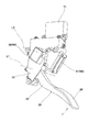
このアクセルペダル装置は、図1ないし図4に示すように、自動車等の車体に固定されるハウジング10、所定の軸線L1を中心として揺動自在に支持されたアクセルペダル20、アクセルペダル20を休止位置に戻す付勢力を及ぼす復帰バネ30、アクセルペダル20を休止位置に戻す付勢力を及ぼすと共に踏力(ペダル荷重)にヒステリシスを発生させるための(第1スライダ41,第2スライダ42,及び復帰バネ43等を含む)ヒステリシス発生機構40、アクセルペダル20の回転角度位置及びその回転の向きを検出する検出手段としてのアクセル位置センサ(APS)50、所定条件下においてアクセルペダル20を休止位置に向けて押し戻す反力を生じさせるための(トルクモータ61,戻しレバー62,モータ位置センサ(MPS)63等を含む)反力付加機構60、反力付加機構60の駆動制御を行う制御手段としての制御システム70等を備えている。
Hereinafter, embodiments of the present invention will be described with reference to the accompanying drawings.
As shown in FIGS. 1 to 4, the accelerator pedal device includes a
ハウジング10は、全体が樹脂材料により成形されており、図1ないし図3に示すように、アクセルペダル20を軸線L1回りに揺動自在に支持し、その内部において、復帰バネ30及びヒステリシス発生機構40を収容し、又、軸線L1の周りにおいてアクセル位置センサ50を埋設し、その上方領域において外部との電気接続を行う後述の制御ユニット71を埋設するように形成されている。
The
アクセルペダル20は、全体が樹脂材料により成形されており、図1ないし図3に示すように、ハウジング10の支軸10aにより回動自在に支持される円筒部21、円筒部21から下方に伸長して一体的に形成された下側アーム部22、円筒部21から上方に伸長して一体的に形成された上側アーム部23、下側アーム部22に一体的に形成されたペダル部24等を備えている。
上側アーム部23は、ヒステリシス発生機構40の一部(第1スライダ41)及び反力付加機構60の一部(戻しレバー62)と係合するように形成されている。
As shown in FIGS. 1 to 3, the
The
復帰バネ30は、図3に示すように、バネ鋼等により形成された圧縮型のコイルバネであり、その一端部がハウジング10の内壁に係合しかつその他端部がアクセルペダル20(上側アーム部23)の一部に係合して、所定の圧縮代に圧縮された状態で取り付けられて、アクセルペダル20を休止位置に戻す付勢力を及ぼすようになっている。
As shown in FIG. 3, the
ヒステリシス発生機構40は、図3に示すように、ハウジング10に収容された、第1スライダ41、第2スライダ42、復帰バネ43を備えており、アクセルペダル20の上側アーム部23(の上端部)に離脱可能に係合して踏力(ペダル荷重)にヒシテリシスを発生させるように形成されている。
第1スライダ41は、樹脂材料(例えば、含油ポリアセタール等の高摺動性材料)により形成されており、図3に示すように、ハウジング10の下側内壁面10bに摺動自在に接触し、第2スライダ42の傾斜面と接触する傾斜面、上側アーム部23(の上端部)が離脱可能に係合し得る係合面等を備えている。
第2スライダ42は、樹脂材料(例えば、含油ポリアセタール等の高摺動性材料)により形成されており、図3に示すように、ハウジング10の上側内壁面10cに摺動自在に接触し、第1スライダ41の傾斜面と接触する傾斜面、復帰バネ43の一端部を受ける受け面等を備えている。
復帰バネ43は、図3に示すように、バネ鋼等により形成された圧縮型のコイルバネであり、その一端部が第2スライダ42の受け面に係合し、その他端部がハウジング10の内壁に係合して、所定の圧縮代に圧縮された状態で取り付けられて、第2スライダ42の傾斜面を第1スライダ41の傾斜面に押し付けて、第1スライダ41及び第2スライダ42を下側内壁面10b及び上側内壁面10cに向けて押し付けるようなくさび作用を及ぼすと共に、第1スライダ41及び第2スライダ42を介して、アクセルペダル20を休止位置に戻す付勢力を及ぼすようになっている。
As shown in FIG. 3, the
The
The
As shown in FIG. 3, the
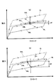
したがって、アクセルペダル20が、復帰バネ30(及び復帰バネ43)の付勢力に抗して最大踏込み位置(全開位置)に向けて踏み込まれる場合は、上側アーム部23が復帰バネ43の付勢力に抗して第1スライダ41を図3中の左向きに押すことで、第1スライダ41及び第2スライダ42のくさび作用により生じる摩擦力(摺動抵抗)が増加し、復帰バネ43の付勢力の増加に伴って摩擦力が直線的に増加し、図5中の実線NLで示すヒステリシス特性の踏込み側の特性ラインDNLが得られる。
一方、アクセルペダル20が、復帰バネ30(及び復帰バネ43)の付勢力に応じて休止位置に向けて戻される場合は、第1スライダ41及び第2スライダ42のくさび作用により生じる摩擦力(摺動抵抗)は小さくなり、復帰バネ43の付勢力により第1スライダ41及び第2スライダ42が元の位置に向けて図3中の右向きに移動するに連れて、復帰バネ43の付勢力が減少することで摩擦力が直線的に減少し、図5中の実線NLで示すヒステリシス特性の戻し側の特性ラインRNLが得られる。
ここで、戻り動作の際の摩擦力は、踏込み動作の際の摩擦力よりも小さくなるため、踏込み動作から戻し動作までの全体の踏力(ペダル荷重)にヒステリシス(実線NL)を発生させることができる。
尚、戻り動作の途中において、第1スライダ41がスティックして停止したときは、復帰バネ30の付勢力により、上側アーム部23が第1スライダ41から離脱することで、アクセルペダル20は所定の休止位置に戻るようになっている。
Accordingly, when the
On the other hand, when the
Here, since the frictional force during the return operation is smaller than the frictional force during the stepping operation, hysteresis (solid line NL) may be generated in the overall pedaling force (pedal load) from the stepping operation to the return operation. it can.
When the
アクセル位置センサ(APS)50は、図2に示すように、軸線L1の周りの領域において、アクセルペダル20の円筒部21及びハウジング10のセンサ収容部に配置されている。
アクセル位置センサ50は、例えば非接触式の磁気式センサであり、アクセルペダル20の円筒部21の領域に設けられた磁性材料からなる環状のアマチャ、アマチャの内周面に結合された円弧状の一対の永久磁石、ハウジング10に埋設された磁性材料からなる二つのステータ、二つのステータ間に配置された2つのホール素子等により形成され、その他に関連する部品として、端子、種々の電子部品が実装された回路基板等が設けられている。
そして、アクセル位置センサ50は、アクセルペダル20が回動(揺動)することにより、磁束密度の変化をホール素子で検出して電圧信号として出力し、アクセルペダル20の角度位置を検出すると共に、その電圧信号の変化量に基づいてアクセルペダル20が踏込み動作にあるか戻し動作にあるかを検出するようになっている。
As shown in FIG. 2, the accelerator position sensor (APS) 50 is disposed in the
The
The
反力付加機構60は、図1ないし図3に示すように、ハウジング10の内部に収容されたトルクモータ61、トルクモータ61に直結されてアクセルペダル20の上側アーム部23に対して離脱可能に係合する戻しレバー62、ハウジング10のセンサ収容部に収容されて戻しレバー62の回転角度を検出するモータ位置センサ(MPS)63等により構成されている。
トルクモータ61は、軸線L2を中心として、それに直結された戻しレバー62を所定の角度範囲において往復動するように一体的に回転させるものである。ここでは、駆動源として、トルクモータ61を示したが、アクセルペダル20の踏力に抵抗して戻しレバー62を回動させることができるものであれば、トルクモータに限らずその他の構成をなす駆動源を適用することができる。
As shown in FIGS. 1 to 3, the reaction
The
戻しレバー62は、図3に示すように、軸線L2を中心に回動するトルクモータ61の回転軸に直結されると共にその先端部がアクセルペダル20の上側アーム部23に離脱可能に係合するように形成されている。
そして、戻しレバー62は、トルクモータ61が駆動力(回転トルク)を及ぼさないとき、アクセルペダル20の揺動に追従するように、すなわち、上側アーム部23の移動に対して抵抗力を及ぼすことなく追従するように自由に回動し、一方、トルクモータ61が駆動力(回転トルク)を及ぼすとき、踏力に抵抗してアクセルペダル20を休止位置に向けて押し戻す反力を上側アーム部23に対して及ぼすようになっている。
As shown in FIG. 3, the
The
モータ位置センサ(MPS)63は、図1に示すように、ハウジング10のセンサ収容部に配置されており、トルクモータ61の回転角度すなわち戻しレバー62の角度位置を検出するようになっている。尚、モータ位置センサ63としては、接触式又は非接触式のセンサを適用することができる。
ここでは、反力付加機構60が、トルクモータ61、戻しレバー62、モータ位置センサ63により構成されているため、反力付加機構60の簡素化及び装置の小型化等が達成され、所定条件下で反力を付加する制御が必要になった場合の応答性を高めることができる。
As shown in FIG. 1, the motor position sensor (MPS) 63 is disposed in the sensor housing portion of the
Here, since the reaction
制御システム70は、図4に示すように、ハウジング10に埋設される制御ユニット71、車両に搭載されて全体の制御を司るECU72、車両に搭載されたバッテリ73、車両又はエンジンの種々の運転状態を検出する運転状態検出手段としての運転状態検出回路74等を備えている。
制御ユニット70は、ハウジング10の上方領域に埋設されており、制御を司るマイコン(チップ)71a、マイコン71aの制御信号に基づいてトルクモータ61を駆動する駆動回路71b、トルクモータ61を駆動する駆動電流を検出する電流検出回路71c、モータ検出センサ(MPS)63の検出信号をマイコン71aに送るMPS入力回路71d、マイコン71aとECU72との間でCAN(Controller Area Network)通信により信号(データ)の送受信を行うインターフェース回路71e、マイコン71aに電源を導く電源回路71fを備えている。また、アクセル位置センサ(APS)50は、検出信号をECU72に送信するように接続されている。
運転状態検出回路74は、種々の運転情報(例えば、車速、エンジン回転数、前方車両との距離、路面情報、運転モード等)を検出するものである。
そして、運転状態検出回路74により、種々の運転情報が検出されると、ECU72及び制御ユニット71を介して、運転者に違和感を生じさせることなく、最適な状態で素早く危険を回避し又危険を告知し、さらには、燃費を低減するように、反力付加機構60が適宜駆動制御されるようになっている。
As shown in FIG. 4, the
The
The driving
Then, when various driving information is detected by the driving
ここで、制御システム70による反力付加機構60の駆動制御について説明する。
制御システム70は、運転状態検出回路74の検出情報に基づき、所定条件下において、アクセルペダル20の踏込み時に反力を付加すると共に、所定条件下において、アクセルペダル20の戻し時にも反力を付加するように、反力付加機構60を駆動制御するようになっている。
ここで、アクセルペダル20の踏込み動作時及び戻し動作時の全域において、反力を付加した場合の踏力は、図5中の一点鎖線ALで示すヒステリシス特性(踏込み側の特性ラインDAL、戻し側の特性ラインRAL)となる。すなわち、反力を付加しない通常のヒステリシス特性(実線NL/踏込み側の特性ラインDNL、戻し側の特性ラインRNL)に対して、全体的に反力Faを付加した特性となる。
Here, drive control of the reaction
Based on the detection information of the driving
Here, the pedal force when the reaction force is applied in the entire range of the
これによれば、運転者がアクセルペダル20を操作して休止位置と最大踏み込み位置の間で揺動させる際に、ヒステリシス発生機構40によりヒステリシスを生じるような踏力が得られ、かつ、所定条件下で(例えば、車両の運転中に前方を走行している車両との車間距離が短くなったとき等、危険回避あるいは危険告知等が必要なった場合に)は、制御システム70により反力付加機構60が駆動されて、運転者の踏込み動作時だけでなく戻し動作時においても、踏力に対抗してアクセルペダル20を押し戻すような反力(押し戻し力)を発生させることができる。
したがって、アクセルペダル20の戻しが遅い場合や戻し量が足りない場合等に、アクセルペダル20の戻し動作に反力を付加して戻し動作をアシストすることで、即座に危険を回避することができる。
According to this, when the driver operates the
Therefore, when the return of the
また、制御システム70は、踏力のヒステリシスにおける踏込み側の踏力(特性ラインDNL)と戻し側の踏力(特性ラインRNL)との差分(例えば、最大踏込み位置での差分ΔFmax)の踏力よりも大きな反力(例えば、最大踏込み位置で付加される反力Fa(Fa>ΔFmax)を付加するように反力付加機構60を駆動制御する。
これによれば、アクセルペダル20の踏込み動作時に(踏力のヒステリシス特性において、踏込み側の特性ラインDNLに沿う状態で)反力が付加される場合、その反力によりアクセルペダル20が若干押し戻されて、その踏力は踏込み時にもかかわらず反力が付加されたヒステリシス特性の戻し側の特性ラインRALに沿うことになる。ここで、仮に踏込み側の踏力と戻し側の踏力との差分の踏力よりも小さい反力が付加されると、その踏力は、反力が付加された戻し側の踏力特性ラインRALが、反力を付加しない踏込み側の踏力特性ラインDNLよりも小さくなるため、運転者はその反力感を明確に認識することができない虞があるが、ここでは、図5に示すように、踏込み側の踏力と戻し側の踏力との差分の踏力よりも大きい反力Fa(>ΔFmax)が付加されるため、その踏力は、そのアクセル開度(ストローク)位置での反力が付加されない踏込み側の踏力よりも大きくなり、運転者はその反力感を明確に認識することがでる。
Further, the
According to this, when a reaction force is added during the depression operation of the accelerator pedal 20 (in the state of the hysteresis characteristic of the depression force along the depression-side characteristic line DNL), the
また、図6(a),(b)に示すように、ヒステリシス発生機構40を備えたアクセルペダル装置において、アクセルペダル20の踏込み時に(図6(a)中のP1点において)反力を付加した場合、その反力によりアクセルペダル20が若干押し戻されて、その踏力は踏込み時にもかかわらず反力が付加されたヒステリシス特性(一点鎖線AL)の戻し側の特性ラインRALに沿う(図6(a)中のP2点に移行する)ようになる。
ここで、踏込み時に付加する反力と戻し時に付加する反力が同じ場合、アクセルペダル20の押し戻しも僅かであり、運転者はその付加された反力に気付き難い。また、図6(a),(b)に示すように、踏込み時に付加されたと感じる反力ΔDFは、戻し時に付加されたと感じる反力ΔRFよりも小さいため、運転者は反力に違和感を覚える虞がある。
Further, as shown in FIGS. 6A and 6B, in the accelerator pedal device having the
Here, when the reaction force applied at the time of depressing is the same as the reaction force applied at the time of return, the
そこで、制御システム70は、図7(a),(b)に示すように、アクセルペダル20の踏込み時に付加する反力Fadがアクセルペダル20の戻し時に付加する反力Farよりも大きくなるように、反力付加機構60を駆動制御するようになっている。
これによれば、アクセルペダル20の踏込み時に(図7(a)中のP3点において)反力を付加した場合、その反力によりアクセルペダル20が図6(a)に示す場合よりも大きく押し戻されて、その踏力は反力が付加されたヒステリシス特性(一点鎖線AL)の戻し側の特性ラインRALに沿う(図7(a)中のP4点に移行する)ようになる。
このとき、運転者はアクセルペダル20の押し戻し(反力)を確実に感じることができ、又、図7(a),(b)に示すように、踏込み時に付加されたと感じる反力ΔDF´が、戻し時に付加されたと感じる反力ΔRFと略同等であるため、運転者は反力に違和感を覚えることなく、最適なアクセルフィーリングを実現することができる。
Therefore, as shown in FIGS. 7A and 7B, the
According to this, when the reaction force is applied when the
At this time, the driver can surely feel the pushing back (reaction force) of the
さらに、制御システム70は、反力を付加した後に、アクセル位置センサ50により得られるアクセルペダル20の動作情報(踏込み動作にあるいか戻し動作にあるか)に基づいて、さらに反力を付加するか否かを判断し、反力を付加する必要があると判断したときは、反力付加機構60を駆動制御して所定の反力を付加するようになっている。
すなわち、反力を付加した後にアクセルペダル20が戻されるような動作にあれば反力は付加されないが、反力を付加した後でもアクセルペダル20がさらに踏み込まれるような動作にあれば、さらに反力を付加するように反力付加機構60を駆動制御することで、危険等から完全に回避することができ、又、危険の告知を連続して行うことができる。
このように、アクセル位置センサ50の検出情報に基づいて、アクセルペダル20の動作が踏込み動作か戻し動作か判断され、その判断結果に基づいて、反力付加機構60による反力の付加が行われるため、アクセルペダル20の動作を反力の付加制御に直接的に反映させることができ、アクセルペダル20の踏込み時及び戻し時においてそれぞれ高精度に所望のタイミングで反力を付加することができる。
Furthermore, the
That is, the reaction force is not applied if the operation is such that the
Thus, based on the detection information of the
ここで、反力の増減は、制御システム70により、トルクモータ61の駆動電流を適宜調整して、必要とされる反力の大きさを適宜設定するようになっている。
このように、反力付加機構60としてトルクモータ61を採用するため、構造の簡素化等を達成しつつ、簡単な制御手法で反力を付加することができる。
上記のように、制御システム70は、運転情報検出回路74により検出される種々の運転情報(例えば、車速、エンジン回転数、前方車両との距離、路面情報、運転モード等)に基づいて、反力付加機構60を適宜駆動制御するため、運転者に違和感を生じさせることなく、最適な状態で素早く危険を回避し又危険を告知することができ、又、燃費を低減することもできる。
Here, the reaction force is increased or decreased by appropriately adjusting the drive current of the
Thus, since the
As described above, the
次に、このアクセルペダル装置の動作について説明する。
先ず、運転者がアクセルペダル20を踏み込まない休止位置にあるとき、復帰バネ30の付勢力により、アクセルペダル20は休止位置に停止している。
この状態から、運転者がアクセルペダル20を踏み込むと、復帰バネ30の付勢力に抗して図3中の反時計回りに回転し、ヒステリシス発生機構40が発生する抵抗荷重(押返し荷重)を増しながら、最大踏込み位置(全開位置)まで回転して、所定のストッパに当接して停止する。この踏込み動作において、戻しレバー62は、何ら負荷(押し戻し力)を及ぼすことなく、上側アーム部23の移動に追従するようになっている。
Next, the operation of this accelerator pedal device will be described.
First, when the driver is at a rest position where the
When the driver depresses the
一方、運転者が踏力を緩めると、踏込み時の抵抗荷重(ペダル荷重)よりも小さい抵抗荷重(ペダル荷重)を運転者に及ぼしながら、アクセルペダル20は復帰バネ30の付勢力により休止位置に向けて移動し、所定のストッパに当接して停止する。この戻し動作において、戻しレバー62は、何ら負荷(押し戻し力)を及ぼすことなく、第1スライダ41に押されて、上側アーム部23の移動に追従するようになっている。
On the other hand, when the driver loosens the pedaling force, the
ここで、運転者がアクセルペダル20を踏み込む踏込み動作にあるとき、例えば、危険回避あるいは危険告知が必要と判断された場合(所定条件下において)は、制御システム70の制御信号に基づいて、反力付加機構60のトルクモータ61が起動し、戻しレバー62が図3中において時計回りの回転トルク(押し戻し力)を発生して、運転者の踏力に対抗してアクセルペダル20(の上側アーム部23)を休止位置に向けて押し戻すように、戻し時に付加される反力Farよりも大きい反力Fad(>Far)が付加されるように駆動制御される。これにより、運転者は確実に反力を感じることができ、即座に危険な状況等を認識することができる。
Here, when the driver is depressing the
一方、運転者がアクセルペダル20を戻す戻し動作にあるとき、例えば、即座の危険回避まるいは危険告知が必要と判断された場合(所定条件下において)は、制御システム70の制御信号に基づいて、反力付加機構60のトルクモータ61が起動し、戻しレバー62が図3中において時計回りの回転トルク(押し戻し力)を発生して、運転者の踏力に対抗してアクセルペダル20(の上側アーム部23)を休止位置に向けてさらに押し戻すように、反力Farが付加されるように駆動制御される。これにより、運転者は確実に反力を感じることができ、即座に危険な状況等を認識することができる。
このように、所定の条件下において(例えば、車両の運転中に前方を走行している車両との車間距離が短くなったとき等、危険回避あるいは危険告知等が必要なった場合に)、制御システム70により反力付加機構60が適宜駆動されて、運転者の踏込み動作時だけでなく戻し動作時においても、踏力に対抗してペダルアーム20を押し戻すような反力(押し戻し力)を発生させて、アクセルペダル20の戻しが遅い場合や戻し量が足りない場合等に、アクセルペダル20の戻し動作をアシストすることで、即座に危険を回避することができる。
On the other hand, when the driver is in the returning operation of returning the
In this way, the control is performed under a predetermined condition (for example, when danger avoidance or danger notification is required, for example, when the distance between the vehicle and the vehicle traveling ahead is shortened while driving the vehicle). The reaction
尚、反力付加機構60が仮に作動不良になっても、戻しレバー62はアクセルペダル20の上側アーム部23に対して離脱可能であるため、アクセルペダル20の安全側(休止位置)への戻りを確実に保証することができ、さらに、ヒシテリシス発生機構40及び反力付加機構60が作動不良になっても、復帰バネ30が直接付勢力を及ぼしているため、アクセルペダル20の安全側(休止位置)への戻りを確実に保証することができる。
Even if the reaction
上記実施形態においては、反力付加機構として、トルクモータ61、戻しレバー62、モータ位置センサ(MPS)63により構成された反力付加機構60を示したが、これに限定されるものではなく、所定の反力を付加できるものであれば、その他の機構を採用することができる。
上記実施形態においては、ヒステリシス発生機構として、第1スライダ41、第2スライダ42、及び復帰バネ43により構成されたヒステリシス発生機構40を示したが、これに限定されるものではなく、踏力に所定のヒステリシスを発生させるものであれば、その他の機構を採用することができる。
上記実施形態においては、アクセルペダルとして、アクセルペダル20がハウジング10内の支軸により揺動自在に支持されたアクセルペダル20を示したが、これに限定されるものではなく、アクセルペダルが車両等の床面に揺動自在に支持されたペダル、ハウジングの支軸により揺動自在に支持されたペダルアーム、ペダルとペダルアームとを連動させるリンク機構等を備えたアクセルペダルを採用してもよい。
In the above embodiment, the reaction
In the above-described embodiment, the
In the above embodiment, the
以上述べたように、本発明のアクセルペダル装置は、アクセルペダルの動作(踏込み動作及び戻し動作)において素早く危険を回避し又は危険を告知でき、又、反力を付加する際に運転者に違和感を生じさせない最適なアクセルフィーリングを得ることができるため、自動車等に適用できるのは勿論のこと、二輪車、作業車両、その他の車両等においても有用である。 As described above, the accelerator pedal device according to the present invention can quickly avoid danger or notify the danger in the operation of the accelerator pedal (depressing operation and returning operation), and also feel uncomfortable to the driver when adding a reaction force. Therefore, it can be applied to automobiles and the like, and is also useful for two-wheeled vehicles, work vehicles, other vehicles, and the like.
L1 軸線
L2 軸線
10 ハウジング
10a 支軸
10b 下側内壁面
10c 上側内壁面
20 アクセルペダル
21 円筒部
22 下側アーム部
23 上側アーム部
24 ペダル部
30 復帰バネ
40 ヒステリシス発生機構
41 第1スライダ
42 第2スライダ
43 復帰バネ
50 アクセル位置センサ(検出手段)
60 反力付加機構
61 トルクモータ
62 戻しレバー
63 モータ位置センサ
70 制御システム(制御手段)
71 制御ユニット(制御手段)
71a マイコン
71b 駆動回路
71c 電流検出回路
71d MPS入力回路
71e インターフェース回路
71f 電源回路
72 ECU
73 バッテリ
74 運転状態検出回路(運転状態検出手段)
L1
60 Reaction
71 Control unit (control means)
73
Claims (4)
前記アクセルペダルの踏力にヒステリシスを発生させるべく,ハウジングに摺動自在に収容されると共に前記アクセルペダルに離脱可能に係合するスライダ及び前記スライダを前記ハウジングに押し付けつつ前記アクセルペダルに向けて付勢するバネを含むヒステリシス発生機構と、
前記アクセルペダルを休止位置に向けて押し戻す反力を付加する反力付加機構と、
前記反力付加機構を駆動制御する制御手段と、を備えたアクセルペダル装置であって、
前記制御手段は、所定条件下において前記アクセルペダルの踏込み時に反力を付加すると共に所定条件下において前記アクセルペダルの戻し時に反力を付加し、かつ、前記踏力のヒステリシスにおける踏込み側の踏力と戻し側の踏力との差分の踏力よりも大きな反力を前記踏込み時及び戻し時において付加すると共に前記踏込み時に付加する反力が前記戻し時に付加する反力よりも大きくなるように、前記反力付加機構を駆動制御する、
ことを特徴とするアクセルペダル装置。 An accelerator pedal,
In order to generate hysteresis in the pedaling force of the accelerator pedal , the slider is slidably received in the housing and is detachably engaged with the accelerator pedal, and the slider is pressed against the housing while being urged toward the accelerator pedal. A hysteresis generating mechanism including a spring that
A reaction force addition mechanism for adding a reaction force to push back the accelerator pedal toward the rest position;
An accelerator pedal device comprising a control means for driving and controlling the reaction force addition mechanism,
The control means applies a reaction force when the accelerator pedal is depressed under a predetermined condition, adds a reaction force when the accelerator pedal is returned under a predetermined condition, and returns a depression force on the depression side and a return in the depression force hysteresis. The reaction force is applied so that a reaction force larger than the difference in pedaling force from the side pedaling force is applied at the time of stepping and returning and the reaction force applied at the time of stepping is greater than the reaction force applied at the time of returning. Drive and control the mechanism,
An accelerator pedal device characterized by that.
前記制御手段は、前記トルクモータの駆動電流を調整して、反力の大きさを適宜設定する、
ことを特徴とする請求項1に記載のアクセルペダル装置。 The reaction force addition mechanism includes a torque motor that exerts a rotational torque that engages and pushes back the accelerator pedal,
The control means adjusts the driving current of the torque motor and appropriately sets the magnitude of the reaction force.
The accelerator pedal device according to claim 1 .
前記制御手段は、前記検出手段の出力情報に基づいて、前記アクセルペダルが踏込み動作にあるか戻し動作にあるかを判断し、前記反力付加機構を駆動制御する、
ことを特徴とする請求項1又は2いずれか一つに記載のアクセルペダル装置。 Detecting means for detecting the operation of the accelerator pedal,
The control means determines, based on output information of the detection means, whether the accelerator pedal is in a depressing action or a returning action, and drives and controls the reaction force adding mechanism.
The accelerator pedal device according to any one of claims 1 and 2 , wherein the accelerator pedal device is provided.
前記制御手段は、前記運転状態検出手段の検出情報に基づいて、前記反力付加機構を駆動制御する、
ことを特徴とする請求項1ないし3いずれか一つに記載のアクセルペダル装置。 Including driving state detecting means for detecting the driving state of the vehicle or the driving state of the engine,
The control means drives and controls the reaction force addition mechanism based on detection information of the driving state detection means.
The accelerator pedal device according to any one of claims 1 to 3 , wherein the accelerator pedal device is provided.
Priority Applications (3)
| Application Number | Priority Date | Filing Date | Title |
|---|---|---|---|
| JP2011036863A JP5806480B2 (en) | 2011-02-23 | 2011-02-23 | Accelerator pedal device |
| EP12156472.8A EP2492130B1 (en) | 2011-02-23 | 2012-02-22 | Accelerator pedal apparatus |
| US13/403,035 US8738261B2 (en) | 2011-02-23 | 2012-02-23 | Accelerator pedal apparatus |
Applications Claiming Priority (1)
| Application Number | Priority Date | Filing Date | Title |
|---|---|---|---|
| JP2011036863A JP5806480B2 (en) | 2011-02-23 | 2011-02-23 | Accelerator pedal device |
Publications (2)
| Publication Number | Publication Date |
|---|---|
| JP2012171526A JP2012171526A (en) | 2012-09-10 |
| JP5806480B2 true JP5806480B2 (en) | 2015-11-10 |
Family
ID=45656385
Family Applications (1)
| Application Number | Title | Priority Date | Filing Date |
|---|---|---|---|
| JP2011036863A Active JP5806480B2 (en) | 2011-02-23 | 2011-02-23 | Accelerator pedal device |
Country Status (3)
| Country | Link |
|---|---|
| US (1) | US8738261B2 (en) |
| EP (1) | EP2492130B1 (en) |
| JP (1) | JP5806480B2 (en) |
Families Citing this family (22)
| Publication number | Priority date | Publication date | Assignee | Title |
|---|---|---|---|---|
| JP5524552B2 (en) * | 2009-09-24 | 2014-06-18 | 株式会社ミクニ | Accelerator pedal device |
| JP5742585B2 (en) * | 2011-08-24 | 2015-07-01 | マツダ株式会社 | Accelerator pedal device |
| JP5641372B2 (en) * | 2012-09-26 | 2014-12-17 | 株式会社デンソー | Accelerator device |
| JP5720960B2 (en) * | 2012-10-04 | 2015-05-20 | 株式会社デンソー | Accelerator device |
| DE102012218283A1 (en) * | 2012-10-08 | 2014-04-10 | Robert Bosch Gmbh | Active accelerator pedal |
| DE102012220383A1 (en) * | 2012-11-08 | 2014-05-08 | Robert Bosch Gmbh | Active accelerator pedal |
| KR101417421B1 (en) * | 2012-11-21 | 2014-07-08 | 현대자동차주식회사 | Active control method of accelerator pedal effort |
| US9459649B2 (en) | 2013-03-15 | 2016-10-04 | Cts Corporation | Active force pedal assembly |
| KR101406592B1 (en) * | 2013-05-07 | 2014-06-11 | 기아자동차주식회사 | Active control method of accelerator pedal effort |
| JP5473102B1 (en) * | 2013-06-04 | 2014-04-16 | 修 井上 | Accelerator equipment for automobiles |
| CN104228573B (en) * | 2013-06-17 | 2017-03-22 | 上海海拉电子有限公司 | Delay generating mechanism and vehicle pedal with same |
| BR112015011785B1 (en) * | 2013-10-04 | 2021-11-16 | Honda Motor Co., Ltd | VEHICLE ACCELERATOR DEVICE |
| SE538210C2 (en) * | 2014-07-07 | 2016-04-05 | Cj Automotive Ab | Mechanical link system for pedal device |
| JP6260794B2 (en) * | 2015-03-19 | 2018-01-17 | マツダ株式会社 | Engine control device |
| JP6198768B2 (en) * | 2015-04-27 | 2017-09-20 | 本田技研工業株式会社 | Pedal reaction force applying device |
| JP6693396B2 (en) * | 2016-11-30 | 2020-05-13 | トヨタ自動車株式会社 | Accelerator pedal reaction force application device |
| JP6823292B2 (en) * | 2017-06-22 | 2021-02-03 | マツダ株式会社 | Vehicle control device |
| JP6870595B2 (en) * | 2017-11-29 | 2021-05-12 | トヨタ自動車株式会社 | Vehicle pedal device |
| KR102035050B1 (en) * | 2018-05-25 | 2019-10-22 | 경창산업주식회사 | Accelerator pedal for vehicle |
| JP7258919B2 (en) * | 2019-02-01 | 2023-04-17 | 株式会社ミクニ | accelerator pedal device |
| CN118234645A (en) * | 2021-11-19 | 2024-06-21 | Ksr Ip控股有限责任公司 | Passive force simulator pedal assembly |
| SE2251572A1 (en) * | 2022-12-23 | 2024-06-24 | Cj Automotive Ab | Pedal arrangement for a vehicle and vehicle having such a pedal arrangement |
Family Cites Families (22)
| Publication number | Priority date | Publication date | Assignee | Title |
|---|---|---|---|---|
| JP3983495B2 (en) * | 2001-04-25 | 2007-09-26 | 株式会社日立製作所 | VEHICLE PEDAL DEVICE AND VEHICLE HAVING THE SAME |
| JP3531640B2 (en) * | 2002-01-10 | 2004-05-31 | 日産自動車株式会社 | Driving operation assist device for vehicles |
| JP3573134B2 (en) * | 2002-02-25 | 2004-10-06 | 日産自動車株式会社 | Driving operation assist device for vehicles |
| JP3651793B2 (en) * | 2002-04-03 | 2005-05-25 | 本田技研工業株式会社 | Accelerator pedal device for vehicle |
| JP3700682B2 (en) * | 2002-06-20 | 2005-09-28 | 日産自動車株式会社 | Accelerator pedal device |
| JP2004314871A (en) * | 2003-04-18 | 2004-11-11 | Nissan Motor Co Ltd | Control device for foot force on accelerator pedal |
| JP2005090347A (en) * | 2003-09-17 | 2005-04-07 | Honda Motor Co Ltd | Accelerator pedal device for vehicle |
| JP4367089B2 (en) * | 2003-10-30 | 2009-11-18 | 日産自動車株式会社 | Accelerator pedal force control device |
| JP4254501B2 (en) * | 2003-11-20 | 2009-04-15 | 日産自動車株式会社 | VEHICLE DRIVE OPERATION ASSISTANCE DEVICE AND VEHICLE HAVING VEHICLE DRIVE OPERATION ASSISTANCE DEVICE |
| JP4367254B2 (en) * | 2004-06-16 | 2009-11-18 | 日産自動車株式会社 | VEHICLE DRIVE OPERATION ASSISTANCE DEVICE AND VEHICLE HAVING VEHICLE DRIVE OPERATION ASSISTANCE DEVICE |
| JP2007145119A (en) * | 2005-11-25 | 2007-06-14 | Toyota Motor Corp | Vehicular control device |
| JP4915112B2 (en) * | 2006-03-10 | 2012-04-11 | 日産自動車株式会社 | Inter-vehicle maintenance support device and inter-vehicle maintenance support method |
| DE102006012515B4 (en) * | 2006-03-18 | 2019-05-29 | Bayerische Motoren Werke Aktiengesellschaft | Motor vehicle with hybrid drive |
| GB0615670D0 (en) * | 2006-08-07 | 2006-09-13 | Syngenta Participations Ag | Chemical compounds |
| JP4835539B2 (en) * | 2007-08-10 | 2011-12-14 | トヨタ自動車株式会社 | Driving force control device |
| JP5278161B2 (en) * | 2008-07-29 | 2013-09-04 | 日産自動車株式会社 | Accelerator pedal reaction force control device |
| JP4553057B2 (en) * | 2008-07-31 | 2010-09-29 | 日産自動車株式会社 | Accelerator pedal depression force control device and method |
| JP5375557B2 (en) * | 2009-03-27 | 2013-12-25 | 日産自動車株式会社 | Accelerator pedal reaction force applying apparatus and method for vehicle |
| JP5407483B2 (en) * | 2009-03-27 | 2014-02-05 | 日産自動車株式会社 | Accelerator pedal reaction force applying device for vehicle |
| JP5269685B2 (en) * | 2009-04-20 | 2013-08-21 | 本田技研工業株式会社 | Vehicle collision avoidance device |
| JP5675016B2 (en) * | 2010-12-01 | 2015-02-25 | 株式会社ミクニ | Accelerator pedal device |
| JP5740175B2 (en) * | 2011-02-21 | 2015-06-24 | 株式会社ミクニ | Accelerator pedal device |
-
2011
- 2011-02-23 JP JP2011036863A patent/JP5806480B2/en active Active
-
2012
- 2012-02-22 EP EP12156472.8A patent/EP2492130B1/en active Active
- 2012-02-23 US US13/403,035 patent/US8738261B2/en active Active
Also Published As
| Publication number | Publication date |
|---|---|
| US8738261B2 (en) | 2014-05-27 |
| US20120221220A1 (en) | 2012-08-30 |
| EP2492130A2 (en) | 2012-08-29 |
| EP2492130A3 (en) | 2016-12-07 |
| JP2012171526A (en) | 2012-09-10 |
| EP2492130B1 (en) | 2018-12-05 |
Similar Documents
| Publication | Publication Date | Title |
|---|---|---|
| JP5806480B2 (en) | Accelerator pedal device | |
| JP5452108B2 (en) | Accelerator pedal device | |
| CN113165507B (en) | Accelerator pedal device | |
| US9108510B2 (en) | Method and control device for controlling foreseeable haptically perceivable signals in an acceleration pedal of a motor vehicle | |
| JP5728563B2 (en) | Reaction force pedal device | |
| JP5740175B2 (en) | Accelerator pedal device | |
| JP2007137152A (en) | Accelerator pedal device | |
| JP4685491B2 (en) | Pedal device | |
| US20130047776A1 (en) | Drive pedal unit for motor vehicles | |
| JP2011068175A (en) | Accelerator pedal device | |
| JP5524552B2 (en) | Accelerator pedal device | |
| JP6033197B2 (en) | Reaction force output device | |
| US20120125142A1 (en) | Accelerator pedal for vehicle | |
| JP2006176001A (en) | Pedal reaction control device | |
| JP5780858B2 (en) | Accelerator pedal reaction force control device | |
| JP6073361B2 (en) | Tactile accelerator pedal provided with actuator driven by DC motor, and control method of tactile accelerator pedal | |
| JP2007022395A (en) | Control device for pedal reaction force | |
| WO2016140262A1 (en) | Reaction force output device | |
| JP2009037513A (en) | Pedal device | |
| JP2015500175A5 (en) | ||
| JP2020124934A (en) | Accelerator pedal device | |
| JP2013189044A (en) | Accelerator pedal device | |
| JP2017182667A (en) | Operating device | |
| KR20040107680A (en) | parking brake control apparatus |
Legal Events
| Date | Code | Title | Description |
|---|---|---|---|
| A621 | Written request for application examination |
Free format text: JAPANESE INTERMEDIATE CODE: A621 Effective date: 20140115 |
|
| A977 | Report on retrieval |
Free format text: JAPANESE INTERMEDIATE CODE: A971007 Effective date: 20141120 |
|
| A131 | Notification of reasons for refusal |
Free format text: JAPANESE INTERMEDIATE CODE: A131 Effective date: 20141125 |
|
| A521 | Request for written amendment filed |
Free format text: JAPANESE INTERMEDIATE CODE: A523 Effective date: 20150119 |
|
| A131 | Notification of reasons for refusal |
Free format text: JAPANESE INTERMEDIATE CODE: A131 Effective date: 20150519 |
|
| A521 | Request for written amendment filed |
Free format text: JAPANESE INTERMEDIATE CODE: A523 Effective date: 20150714 |
|
| TRDD | Decision of grant or rejection written | ||
| A01 | Written decision to grant a patent or to grant a registration (utility model) |
Free format text: JAPANESE INTERMEDIATE CODE: A01 Effective date: 20150811 |
|
| A61 | First payment of annual fees (during grant procedure) |
Free format text: JAPANESE INTERMEDIATE CODE: A61 Effective date: 20150904 |
|
| R150 | Certificate of patent or registration of utility model |
Ref document number: 5806480 Country of ref document: JP Free format text: JAPANESE INTERMEDIATE CODE: R150 |
|
| R250 | Receipt of annual fees |
Free format text: JAPANESE INTERMEDIATE CODE: R250 |
|
| R250 | Receipt of annual fees |
Free format text: JAPANESE INTERMEDIATE CODE: R250 |
|
| R250 | Receipt of annual fees |
Free format text: JAPANESE INTERMEDIATE CODE: R250 |
|
| R250 | Receipt of annual fees |
Free format text: JAPANESE INTERMEDIATE CODE: R250 |
|
| R250 | Receipt of annual fees |
Free format text: JAPANESE INTERMEDIATE CODE: R250 |
|
| R250 | Receipt of annual fees |
Free format text: JAPANESE INTERMEDIATE CODE: R250 |
|
| S111 | Request for change of ownership or part of ownership |
Free format text: JAPANESE INTERMEDIATE CODE: R313117 |
|
| R350 | Written notification of registration of transfer |
Free format text: JAPANESE INTERMEDIATE CODE: R350 |
|
| R250 | Receipt of annual fees |
Free format text: JAPANESE INTERMEDIATE CODE: R250 |