JP4915112B2 - Inter-vehicle maintenance support device and inter-vehicle maintenance support method - Google Patents
Inter-vehicle maintenance support device and inter-vehicle maintenance support method Download PDFInfo
- Publication number
- JP4915112B2 JP4915112B2 JP2006066547A JP2006066547A JP4915112B2 JP 4915112 B2 JP4915112 B2 JP 4915112B2 JP 2006066547 A JP2006066547 A JP 2006066547A JP 2006066547 A JP2006066547 A JP 2006066547A JP 4915112 B2 JP4915112 B2 JP 4915112B2
- Authority
- JP
- Japan
- Prior art keywords
- reaction force
- accelerator pedal
- operation reaction
- accelerator
- inter
- Prior art date
- Legal status (The legal status is an assumption and is not a legal conclusion. Google has not performed a legal analysis and makes no representation as to the accuracy of the status listed.)
- Expired - Lifetime
Links
Images


Landscapes
- Auxiliary Drives, Propulsion Controls, And Safety Devices (AREA)
- Control Of Driving Devices And Active Controlling Of Vehicle (AREA)
- Controls For Constant Speed Travelling (AREA)
Description
本発明は、先行車との車間距離が維持されるように支援する技術に関する。 The present invention relates to a technology for assisting in maintaining a distance between a preceding vehicle and a preceding vehicle.
前方車両との車間距離を検出し、車間距離の減少に伴いアクセルペダルの反力を増大させることによって、運転者の注意を喚起して、車間距離が維持されるように支援する装置が知られている(特許文献1参照)。 A device is known that detects the distance between vehicles ahead and increases the reaction force of the accelerator pedal as the distance between vehicles decreases, thereby alerting the driver and assisting in maintaining the distance between vehicles. (See Patent Document 1).
しかし従来の装置では、前方車両を追い越す場合などドライバが意図的に前方車両に接近する場合にもアクセルペダル反力が増大してしまうため、ドライバがアクセル操作を行う際に違和感を与えてしまう。 However, in the conventional device, the accelerator pedal reaction force increases even when the driver intentionally approaches the preceding vehicle, such as when overtaking the preceding vehicle, so that the driver feels uncomfortable when performing the accelerator operation.
本発明は、自車前方の障害物の状況を検出し、アクセルペダルの操作量を検出し、検出された自車前方の障害物の状況に基づいて、アクセルペダルに発生させるアクセルペダルを押し戻す操作反力を演算し、演算されたアクセルペダルを押し戻す操作反力をアクセルペダルに発生させ、検出された操作量のうち、アクセルペダルを押し戻す操作反力を発生させた後で最も少ない操作量をアクセル開度保存値として記憶し、アクセルペダルを押し戻す操作反力を発生させた後、記憶されたアクセル開度保存値を基準として、検出された操作量が増加したと判断した場合には、アクセル開度保存値と検出された操作量との差をアクセルペダルの踏み増し量として算出し、アクセルペダルを押し戻す操作反力を発生させた後、記憶されたアクセル開度保存値を基準として、検出された操作量が増加したと判断した場合には、算出した踏み増し量に応じて、アクセルペダルに発生させるアクセルペダルを押し戻す操作反力が弱くなるように補正することを特徴とする。
The present invention detects an obstacle state ahead of the host vehicle, detects an operation amount of an accelerator pedal, and pushes back an accelerator pedal to be generated by the accelerator pedal based on the detected obstacle state ahead of the host vehicle. The reaction force is calculated and an operation reaction force that pushes back the calculated accelerator pedal is generated in the accelerator pedal. Of the detected operation amounts, the operation amount that pushes back the accelerator pedal is generated, and then the smallest operation amount is After storing the opening saved value and generating the reaction force that pushes back the accelerator pedal, if it is determined that the detected operation amount has increased based on the stored accelerator opening saved value, The difference between the stored value and the detected operation amount is calculated as the amount of depression of the accelerator pedal. After the operation reaction force that pushes back the accelerator pedal is generated, the stored accelerator opening Based on the stored value, if the amount of detected operation is judged to have increased, according to the calculated depression increment amount, to correct such operation reaction force to push back the accelerator pedal for generating an accelerator pedal is weakened It is characterized by.
本発明によれば、アクセルペダル操作量に基づいてアクセルペダルが踏み増された場合には、アクセルペダルに発生させる操作反力が弱くなるように補正するように構成した。これにより、ドライバがアクセルペダルからブレーキペダルへ踏み替える操作を支援することができるとともに、アクセルペダル反力が発生している状態下でアクセルペダルを踏み込むドライバに対して違和感を低減させることができる。 According to the present invention, when the accelerator pedal is stepped on based on the accelerator pedal operation amount, the operation reaction force generated on the accelerator pedal is corrected so as to be weakened. Accordingly, the driver can assist in the operation of switching from the accelerator pedal to the brake pedal, and can reduce a sense of incongruity for the driver who depresses the accelerator pedal in a state where the accelerator pedal reaction force is generated.
−−−第1の実施の形態−−−
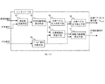
本発明の第1の実施の形態による車間維持支援装置について、図面を用いて説明する。図1は、本発明の第1の実施の形態による車間維持支援装置1の構成を示すシステム図であり、図2は、車間維持支援装置1を搭載する車両の構成図である。
--- First embodiment ---
An inter-vehicle maintenance support device according to a first embodiment of the present invention will be described with reference to the drawings. FIG. 1 is a system diagram showing a configuration of an inter-vehicle
まず、車間維持支援装置1の構成を説明する。レーザレーダ10は、車両の前方グリル部もしくはバンパ部等に取り付けられ、水平方向に赤外光パルスを操作する。レーザレーダ10は、前方にある複数の反射物(通常、前方車の後端)で反射された赤外光パルスの反射波を計測し、反射波の到達時間より、複数の前方車までの車間距離とその存在方向を検出する。検出した車間距離及び存在方向はコントローラ50へ出力される。なお、本実施の形態において、前方物体の存在方向は、自車両に対する相対角度として表すことができる。レーザレーダ10によりスキャンされる前方の領域は、自車正面に対して±6deg程度であり、この範囲内に存在する前方物体が検出される。
First, the configuration of the inter-vehicle
コントローラ50は、車間維持支援装置1全体の制御を行う。コントローラ50は、車速センサ20から入力される自車速と、レーザレーダ10から入力される距離情報から、自車両周囲の障害物状況を検出する。またコントローラ50は、障害物状況に基づいて車間距離閾値を算出する。さらに、コントローラ50は、車間距離閾値に応じて以下のような制御を行う。
The
本発明の第1の実施の形態による車間維持支援装置1は、アクセルペダルを操作する際に発生する反力を制御することによって、運転者の運転操作を適切にアシストするものである。そこで、コントローラ50は、障害物状況から車間距離閾値を算出する。コントローラ50は算出した車間距離閾値に対して目標ペダル反力を算出する。また、コントローラ50はアクセル開度からドライバのアクセル操作を検出し、ドライバがアクセルの踏み込み操作をしたと判断した場合は目標ペダル反力を小さく補正する。そして、コントローラ50は、算出した目標ペダル反力をアクセルペダル反力制御装置60へと出力する。
The inter-vehicle
アクセルペダル反力制御装置60は、コントローラ50から出力される反力制御量に応じて、アクセルペダル62に組み込まれたアクセルペダルアクチュエータ61で発生させるトルクを制御する。アクセルペダルアクチュエータ61は、アクセルペダル操作反力制御装置60からの指令値に応じて発生させる反力を制御し、運転者がアクセルペダル62を操作する際に発生する踏力を任意に制御することができる。
The accelerator pedal reaction
なお、アクセルペダルアクチュエータ61には、不図示の出力軸と、出力軸の回動位置を検出するセンサ61aと設けられている。この出力軸は、アクセルペダル62の不図示の回動軸と連結されており、センサ61aが検出する出力軸の回動位置がアクセルペダル62の操作量と一義的に対応する。したがって、本実施の形態では、このセンサ61aをアクセルペダル62の操作量を検出するアクセルペダル操作量センサとして使用している。
The
図3はコントローラ50で行う処理を示したブロック図である。障害物認識手段51は、レーザレーダ10からの信号を入力し、前方車との車間距離、相対速度を算出し、車速センサ20から入力される自車速とから、自車前方の障害物状況を検出する。車間距離閾値算出手段52は、障害物認識手段51の結果に基づいて車間距離閾値を演算する。目標ペダル反力決定手段53では、車間距離閾値と車間距離とからアクセルペダルに付加する目標ペダル反力を決定する。また、ドライバ操作判断手段54はアクセルペダル操作量センサ61aで検出したアクセルペダル62の操作量に基づいてドライバのアクセル操作を判断する。
FIG. 3 is a block diagram showing processing performed by the
目標ペダル反力補正手段55は、ドライバ操作判断手段54で判断された結果に基づいて、目標ペダル反力決定手段53で決定した目標ペダル反力を補正する。ドライバ操作判断手段54において、ドライバがアクセルの踏み込み操作を行ったと判断した場合に、目標ペダル反力決定手段53で決定した目標ペダル反力を小さく補正する目標ペダル反力補正手段55が本発明の特徴であり、詳細は後述する。 The target pedal reaction force correction means 55 corrects the target pedal reaction force determined by the target pedal reaction force determination means 53 based on the result determined by the driver operation determination means 54. The target pedal reaction force correction means 55 for correcting the target pedal reaction force determined by the target pedal reaction force determination means 53 to be small when the driver operation determination means 54 determines that the driver has depressed the accelerator. This is a feature, and details will be described later.
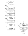
次に実施の形態による車間維持支援装置1の作用を説明する。その作用の概略を以下に述べる。上述した制御において、以下に、図4〜図7を用いて説明する。図4は、本発明の実施の形態によるコントローラ50における車間維持支援制御処理の処理手順を示すフローチャートである。なお、本処理内容は、一定間隔、例えば10msec毎に連続的に行われる。
Next, the operation of the inter-vehicle
まず、ステップS100で走行状態を読み込む。ここで、走行状態は、自車前方の障害物状況を含む自車両の走行状況に関する情報である。そこで、レーザレーダ10により検出される前方障害物までの車間距離や存在方向と、車速センサ20によって検出される自車両の走行車速を読み込む。
First, the travel state is read in step S100. Here, the traveling state is information regarding the traveling state of the host vehicle including the obstacle state ahead of the host vehicle. Therefore, the inter-vehicle distance to the front obstacle detected by the
ステップS200では、ステップS100で読み込み、認識した走行状態データに基づいて、前方障害物の状況を認識する。ここでは、前回の処理周期以前に検出され、不図示のメモリに記憶されている自車両に対する障害物の相対位置やその移動方向・移動速度と、ステップS100で得られた現在の走行状態データとにより、現在の障害物の自車両に対する相対位置やその移動方向・移動速度を認識する。そして、自車両の走行に対して障害物が、自車両の前方にどのように配置され、相対的にどのように移動しているかを認識する。 In step S200, the situation of the front obstacle is recognized based on the driving state data read and recognized in step S100. Here, the relative position of the obstacle with respect to the host vehicle detected before the previous processing cycle and stored in a memory (not shown), its moving direction / speed, and the current running state data obtained in step S100, Thus, the relative position of the current obstacle with respect to the host vehicle, the moving direction and the moving speed thereof are recognized. Then, it is recognized how the obstacle is arranged in front of the host vehicle and how it moves relative to the traveling of the host vehicle.
ステップS300では、車間距離閾値を算出する。ここで行う処理を図5に示すフローチャートを用いて説明する。
ステップS301では車間距離閾値(定常項)L*h2を算出する。車間距離閾値(定常項)は、先行車両が一定速での相当項であり、本実施例では、自車両の車速V及び相対速度Vrに応じて次式(1)により設定する。
L*h2 = f(V,Vr) (1)
ステップS302では、先行車両の加減速度αaを次式(2)により算出する。
αa = d( Va ) / dt (2)
ここで、Vaは先行車両の車速であり、自車両の車速V及び相対速度Vrから算出される。
In step S300, an inter-vehicle distance threshold is calculated. The process performed here is demonstrated using the flowchart shown in FIG.
In step S301, an inter-vehicle distance threshold (steady term) L * h2 is calculated. The inter-vehicle distance threshold (steady term) is an equivalent term when the preceding vehicle is at a constant speed, and is set by the following equation (1) according to the vehicle speed V and the relative speed Vr of the host vehicle in this embodiment.
L * h2 = f (V, Vr) (1)
In step S302, the acceleration / deceleration αa of the preceding vehicle is calculated by the following equation (2).
αa = d (Va) / dt (2)
Here, Va is the vehicle speed of the preceding vehicle, and is calculated from the vehicle speed V and the relative speed Vr of the host vehicle.
ステップS303では、車間距離閾値(過渡項)を算出、更新するための条件として、後述ステップS400において算出される警報フラグFwがセットされているか否かを判断する。
(1) 警報フラグがセットされていない(Fw = OFF)場合、ステップS304に進む。
(2) 警報フラグがセットされている(Fw = ON)場合、車間距離閾値(過渡項)用パラメータを更新せず、ステップS307へ進む。
In step S303, it is determined whether an alarm flag Fw calculated in step S400, which will be described later, is set as a condition for calculating and updating the inter-vehicle distance threshold (transient term).
(1) If the alarm flag is not set (Fw = OFF), the process proceeds to step S304.
(2) If the alarm flag is set (Fw = ON), the parameter for the inter-vehicle distance threshold (transient term) is not updated, and the process proceeds to step S307.
ステップS304では先行車両の減速判断を行う。本実施例では、先行車両の減速度が所定値以上であるか否かで判断される。
(1) 先行車加減速度が所定値以下(αa≦α0)の場合
先行車減速判断フラグFdec_a = ON とする。
(2) 上記以外(αa>α0)の場合
先行車減速判断フラグFdec_a = OFF とする。
ここで、α0は減速判断を行うための閾値である。また、先行車加減速度αa、減速判断閾値α0ともに、加速を正、減速を負の値とする。
In step S304, a deceleration determination of the preceding vehicle is performed. In this embodiment, the determination is made based on whether or not the deceleration of the preceding vehicle is greater than or equal to a predetermined value.
(1) When the preceding vehicle acceleration / deceleration is not more than a predetermined value (αa ≦ α0), the preceding vehicle deceleration judgment flag Fdec_a = ON.
(2) In cases other than the above (αa> α0), the preceding vehicle deceleration determination flag Fdec_a = OFF.
Here, α0 is a threshold value for performing deceleration determination. In addition, acceleration is positive and deceleration is negative both for the preceding vehicle acceleration / deceleration αa and the deceleration determination threshold α0.
ステップS305では、ステップS304において、先行車両が減速したと判断された場合、次式(3)に従い、車間距離閾値(過渡項)用パラメータTr2を算出、更新する。
Tr2 = ( L - L*h2 ) / Vr (3)
上記式により、Tr2は、先行車両が減速を開始した時点での車間距離閾値(定常項)L*h2に対する実車間距離Lの余裕距離相当分を相対速係数時間として表されたものである。
In step S305, if it is determined in step S304 that the preceding vehicle has decelerated, an inter-vehicle distance threshold (transient term) parameter Tr2 is calculated and updated according to the following equation (3).
Tr2 = (L-L * h2) / Vr (3)
From the above equation, Tr2 is expressed as a relative speed coefficient time corresponding to the margin distance of the actual inter-vehicle distance L with respect to the inter-vehicle distance threshold (steady term) L * h2 when the preceding vehicle starts to decelerate.
ステップS306では、ステップS304において、先行車両が減速していないと判断された場合、車間距離閾値(過渡項)用パラメータTr2をクリアする。
Tr2 = 0
ステップS307では下記式に従い、車間距離閾値(過渡項)L*r2を次式(4)により算出する。
L*r2 = Tr2 ×Vr (4)
ステップS308では車間距離閾値L*2を算出する。本実施例では、次式(5)に従い、車間距離閾値(定常項)L*h2と車間距離閾値(過渡項)L*r2の和で算出される。
L*2 = L*h2 + L*r2 (5)
ステップS400では警報フラグをセット、クリアする。
(1) 車間距離偏差ΔL2 ≧ 0 の場合
警報フラグFw = ON とする。
(2) 上記以外(車間距離偏差ΔL2< 0)の場合
警報フラグFw = OFF とする。
In step S306, if it is determined in step S304 that the preceding vehicle has not decelerated, the inter-vehicle distance threshold (transient term) parameter Tr2 is cleared.
Tr2 = 0
In step S307, an inter-vehicle distance threshold (transient term) L * r2 is calculated according to the following equation (4).
L * r2 = Tr2 x Vr (4)
In step S308, an inter-vehicle distance threshold L * 2 is calculated. In the present embodiment, the distance is calculated as the sum of the inter-vehicle distance threshold (steady term) L * h2 and the inter-vehicle distance threshold (transient term) L * r2 according to the following equation (5).
L * 2 = L * h2 + L * r2 (5)
In step S400, an alarm flag is set and cleared.
(1) and when the warning flag Fw = ON car distance deviation [Delta]
(2) In other cases (inter-vehicle
ステップS500では、車間距離閾値L*2に応じて、目標ペダル反力を決定する。目標アクセルペダル反力τ*aは車間距離閾値L*2、及び実車間距離Lから次式(6),(7)のように算出する。
τ*a = Kp × ΔL2 (6)
ΔL2 = L*2 - L (7)
ここで、Kpは、車間距離偏差ΔL2から目標アクセルペダル反力を算出するためのゲインである。このステップS500において算出された目標アクセルペダル反力τ*aに応じて、アクセルペダル反力制御装置60はアクセルペダル62に発生させる反力を制御する。
In step S500, the target pedal reaction force is determined according to the inter-vehicle
τ * a = Kp × ΔL2 (6)
ΔL2 = L * 2-L (7)
Here, Kp is a gain for calculating the target accelerator pedal reaction force from the inter-vehicle distance deviation ΔL2. The accelerator pedal reaction
ステップS600では、ドライバがアクセルの踏み込み操作を行ったか否かを判断する。ここで行う処理を図6に示すフローチャートを用いて説明する。 In step S600, it is determined whether or not the driver has depressed the accelerator. The processing performed here will be described with reference to the flowchart shown in FIG.
ステップS601では、車アクセル開度保存値Acchを更新するための条件として、ステップS400において算出された警報フラグFwがセットされているか否かを判断する。NOの場合はステップS602に進み、アクセル開度保存値Acchにアクセル開度Accをセットし、アクセル踏み込み量ΔAccをクリアする。YESの場合はステップS603に進み、アクセル開度Accがアクセル開度保存値Acchよりも小さいか否かを判断する。YESの場合、ステップS604へ進み、アクセル開度保存値Acchにアクセル開度Accをセットし、アクセル踏み込み量ΔAccをクリアする。ステップS603でNOの場合、ステップS605に進み、アクセル踏み込み量ΔAccを次式(8)に従って算出する。
ΔAcc = Acc - Acch (8)
In step S601, it is determined whether or not the warning flag Fw calculated in step S400 is set as a condition for updating the vehicle accelerator opening stored value Acch. If NO , the process proceeds to step S602, where the accelerator opening Acc is set to the accelerator opening stored value Acch, and the accelerator depression amount ΔAcc is cleared. If YES, the process proceeds to step S603, and it is determined whether or not the accelerator opening Acc is smaller than the accelerator opening stored value Acch. If YES, the process proceeds to step S604, where the accelerator opening Acc is set to the accelerator opening stored value Acch, and the accelerator depression amount ΔAcc is cleared. If NO in step S603, the process proceeds to step S605, and the accelerator depression amount ΔAcc is calculated according to the following equation (8).
ΔAcc = Acc-Acch (8)
ステップS605では、アクセル開度保存値Acchが更新されないので、ステップS602またはステップS604で最後に更新されたアクセル開度保存値Acchを基準としてアクセル踏み込み量ΔAccが算出される。すなわち、ステップS605では、アクセルペダル62の踏み増しが開始されたときのアクセルペダル62の操作量を基準としてアクセル踏み込み量ΔAccが算出される。
In step S605, since the accelerator opening stored value Acch is not updated, the accelerator depression amount ΔAcc is calculated based on the accelerator opening stored value Acch updated last in step S602 or step S604. That is, in step S605, the accelerator depression amount ΔAcc is calculated based on the operation amount of the
ステップS700では、ステップS600で判断したドライバのアクセル操作に基づいて、ステップS500で算出した目標アクセルペダル反力τ*aを補正する。ここで行う処理を図7に示すフローチャートを用いて説明する。 In step S700, based on the driver's accelerator operation determined in step S600, the target accelerator pedal reaction force τ * a calculated in step S500 is corrected. The processing performed here will be described with reference to the flowchart shown in FIG.
まずステップS701では、目標ペダル反力補正係数K_τaを次式(9)に従って算出する。
K_τa = 100 - (ΔAcc × Kacc) (9)
ここで、Kaccはアクセル踏み込み量ΔAccから目標ペダル反力補正係数を算出するためのゲインである。また、目標ペダル反力補正係数K_τaは、最大値を100、最小値を0とする。
First, in step S701, a target pedal reaction force correction coefficient K_τa is calculated according to the following equation (9).
K_τa = 100-(ΔAcc × Kacc) (9)
Here, Kacc is a gain for calculating the target pedal reaction force correction coefficient from the accelerator depression amount ΔAcc. The target pedal reaction force correction coefficient K_τa has a maximum value of 100 and a minimum value of 0.
次にステップS702で目標ペダル反力を補正する。このステップS702で行う処理が本発明の特徴であり、ステップS701で算出した目標ペダル反力補正係数K_τaを用いて、ドライバがアクセルの踏み込み操作をしたときにペダル反力が小さくなるように補正する。本実施例では、次式(10)に従って目標ペダル目標ペダル反力の補正を行う。
τ*ahosei = K_τa × τ*a/100 (10)
In step S702, the target pedal reaction force is corrected. The processing performed in step S702 is a feature of the present invention, and correction is made so that the pedal reaction force is reduced when the driver depresses the accelerator using the target pedal reaction force correction coefficient K_τa calculated in step S701. . In this embodiment, the target pedal target pedal reaction force is corrected according to the following equation (10).
τ * a hosei = K_τa × τ * a / 100 (10)
ステップS800では、ステップS700で算出したアクセルペダル反力補正値τ*ahoseiをアクセルペダル反力制御装置60へ出力する。
In step S800, the accelerator pedal reaction force correction value τ * ahosei calculated in step S700 is output to the accelerator pedal reaction
第1の実施の形態による車間維持支援装置によれば、車間距離Lが車間距離閾値L*2を下回ったとき、アクセルペダル62を押し戻す力をアクセルペダルアクチュエータ61で発生させる。そして、アクセルペダル反力が発生している状態でドライバがアクセルペダル62の踏み込み操作を行った場合に、アクセルペダルアクチュエータ61で発生させているアクセルペダル反力を減少させる補正を行うように構成した。これにより、ドライバがアクセルペダル62からブレーキペダルへ踏み替える操作を支援することができるとともに、アクセルペダル反力が発生している状態下でアクセルペダル62を踏み込むドライバに対して違和感を低減させることができる。
According to the inter-vehicle maintenance support device according to the first embodiment, when the inter-vehicle distance L falls below the inter-vehicle
第1の実施の形態による車間維持支援装置によれば、アクセルペダル反力の補正を行う際に、アクセルペダル62の踏み増し量に応じて、すなわち、ドライバがアクセルペダル62を踏み増すにつれて、アクセルペダルアクチュエータ61で発生させるアクセルペダル反力が弱くなるように補正する。これにより、先行車の追い越しなど、ドライバが意図的にアクセルペダル62を多く踏み込む場合に、アクセルペダル62が踏み込みやすくなるため、操作性が向上する。
According to the inter-vehicle maintenance support device according to the first embodiment, when the accelerator pedal reaction force is corrected, the accelerator pedal is operated according to the amount of depression of the
第1の実施の形態による車間維持支援装置によれば、アクセルペダル62の踏み増しが開始されたときのアクセルペダル62の操作量を基準としてアクセルペダル62のアクセル踏み込み量ΔAcc(踏み増し量)を算出するように構成した。これにより、車両の走行状態によって踏み込みはじめのアクセルペダル62の操作量が異なっていても、アクセルペダル62を踏み込むドライバに対して違和感を低減させることができる。
According to the inter-vehicle maintenance support apparatus according to the first embodiment, the accelerator depression amount ΔAcc (the amount of depression) of the
第1の実施の形態による車間維持支援装置によれば、アクセル開度Accがアクセル開度保存値Acchよりも少なくなったときに、すなわち、アクセルペダル62が戻されて、アクセルペダル62の操作量が踏み増しが開始されたときの操作量よりも少なくなった場合には、アクセルペダル反力を減少させる補正が行われなくなるように構成した。これにより、たとえばドライバが先行車の追い越しを中止するなど、加速操作を中止した場合にも、ドライバがアクセルペダル62からブレーキペダルへ踏み替える操作を支援することができる。
According to the inter-vehicle maintenance support device according to the first embodiment, when the accelerator opening Acc becomes smaller than the accelerator opening stored value Acch, that is, the
−−−第2の実施の形態−−−
第1の実施の形態による車間維持支援装置では、アクセルペダル反力の補正を行う際に、アクセルペダル62の踏み増し量に応じて、すなわち、ドライバがアクセルペダル62を踏み増すにつれて、アクセルペダルアクチュエータ61で発生させるアクセルペダル反力が弱くなるように補正した。第2の実施の形態による車間維持支援装置では、アクセルペダル反力の補正を行う際に、アクセルペダル62の踏み増し量に応じて、すなわち、ドライバがアクセルペダル62を踏み増すにつれて、アクセルペダルアクチュエータ61で発生させるアクセルペダル反力の減少速度が速くなるように補正する。
--- Second Embodiment ---
In the inter-vehicle maintenance support device according to the first embodiment, when the accelerator pedal reaction force is corrected, the accelerator pedal actuator depends on the amount of depression of the
以下、図8〜11を参照して、詳細な処理内容を説明する。以下の説明では、第1の実施の形態と同じ構成要素には同じ符号を付して相違点を主に説明する。特に説明しない点については、第1の実施の形態と同じである。なお、第2の実施の形態における車間維持支援装置の構成は、図1に示す第1の実施の形態における車間維持支援装置の構成と同じである。第2の実施の形態における車両の構成は、図2に示す第1の実施の形態における車両の構成と同じである。また、第2の実施の形態におけるコントローラ50についてのブロック図は、図3に示す第1の実施の形態におけるコントローラ50についてのブロック図と同じである。
Hereinafter, detailed processing contents will be described with reference to FIGS. In the following description, the same components as those in the first embodiment are denoted by the same reference numerals, and different points will be mainly described. Points that are not particularly described are the same as those in the first embodiment. The configuration of the inter-vehicle maintenance support device in the second embodiment is the same as the configuration of the inter-vehicle maintenance support device in the first embodiment shown in FIG. The configuration of the vehicle in the second embodiment is the same as the configuration of the vehicle in the first embodiment shown in FIG. The block diagram of the
図8は、第2の実施の形態によるコントローラ50における車間維持支援制御処理の処理手順を示すフローチャートである。第2の実施の形態によるコントローラ50における車間維持支援制御処理の処理手順は、図4に示したフローチャートとは、ステップS700aで実行される目標ペダル反力補正処理だけが第1の実施の形態と異なり、他は同じである。以下、第2の実施の形態におけるステップS700aで実行される目標ペダル反力補正処理について説明する。
FIG. 8 is a flowchart showing the procedure of the inter-vehicle maintenance support control process in the
ステップS700aでは、ステップS600で判断したドライバのアクセル操作に基づいて、ステップS500で算出した目標アクセルペダル反力τ*aを補正する。ここで行う処理を図9に示すフローチャートを用いて説明する。 In step S700a, the target accelerator pedal reaction force τ * a calculated in step S500 is corrected based on the driver's accelerator operation determined in step S600. The process performed here is demonstrated using the flowchart shown in FIG.
まずステップS701aでは、目標ペダル反力減少量Δτaを算出する。ここで目標ペダル反力減少量Δτa_dは図10に示すようなグラフから、アクセル踏み込み量ΔAccが大きくなるに従って大きくなり、アクセル踏み込み量ΔAccがΔAcc_maxよりも大きいときは、目標ペダル反力減少量Δτa_dが最大値Δτa_d_maxとなるように算出される。 First, in step S701a, a target pedal reaction force reduction amount Δτa is calculated. Here, the target pedal reaction force decrease amount Δτa_d increases from the graph shown in FIG. 10 as the accelerator depression amount ΔAcc increases. When the accelerator depression amount ΔAcc is larger than ΔAcc_max, the target pedal reaction force decrease amount Δτa_d is The maximum value Δτa_d_max is calculated.
次にステップS702aで目標ペダル反力を補正する。このステップS702aで行う処理が本発明の第二の実施例における特徴であり、ステップS701aで算出した目標ペダル反力減少量Δτa_dを用いて、ドライバがアクセルの踏み込み操作をしたときにペダル反力が小さくなるように補正する。このステップS702aで行う処理を図11に示すフローチャートを用いて説明する。 Next, in step S702a, the target pedal reaction force is corrected. The process performed in step S702a is a feature of the second embodiment of the present invention. When the driver depresses the accelerator using the target pedal reaction force reduction amount Δτa_d calculated in step S701a, the pedal reaction force is reduced. Correct to be smaller. The process performed in step S702a will be described with reference to the flowchart shown in FIG.
ステップS711では、アクセルペダル反力補正値τ*ahoseiが目標アクセルペダル反力τ*aよりも大きいか否かを判断する。ステップS711が肯定判断されるとステップS712に進み、アクセルペダル反力補正値τ*ahoseiに目標アクセルペダル反力τ*aをセットしてステップS713に進む。ステップS711が否定判断されると、そのままステップS713に進む。ステップS713では、ドライバがアクセル踏み込み操作をしているか否かを判断する。ステップS713が肯定判断されるとステップS714に進み、アクセルペダル反力補正値τ*ahoseiが目標ペダル反力減少量Δτa_dよりも大きいか否かを判断する。ステップS714が肯定判断されるとステップS715に進み、アクセルペダル反力補正値τ*ahoseiから目標ペダル反力減少量Δτa_dを差し引いてアクセルペダル反力補正値τ*ahoseiにセットする。 In step S711, it is determined whether or not the accelerator pedal reaction force correction value τ * a hosei is larger than the target accelerator pedal reaction force τ * a. If an affirmative determination is made in step S711, the process proceeds to step S712, the target accelerator pedal reaction force τ * a is set to the accelerator pedal reaction force correction value τ * a hosei , and the process proceeds to step S713. If a negative determination is made in step S711, the process proceeds to step S713 as it is. In step S713, it is determined whether or not the driver is depressing the accelerator. If an affirmative determination is made in step S713, the process proceeds to step S714 to determine whether or not the accelerator pedal reaction force correction value τ * a hosei is larger than the target pedal reaction force decrease amount Δτa_d. When step S714 is affirmative determination process proceeds to step S715, and sets the accelerator pedal reaction force correction value tau * a corr is computed by subtracting the target pedal reaction force reduction amount Δτa_d from the accelerator pedal reaction force correction value τ * a hosei.
ステップS714が否定判断されると、ステップS716に進み、アクセルペダル反力補正値τ*ahoseiにゼロをセットする。 If a negative determination is made in step S714, the process proceeds to step S716, and the accelerator pedal reaction force correction value τ * a hosei is set to zero.
ステップS713が否定判断されるとステップS717に進み、目標アクセルペダル反力τ*aがアクセルペダル反力補正値τ*ahoseiと予め定められた目標ペダル反力増加量Δτa_uの和よりも大きいか否かを判断する。ステップS717が肯定判断されるとステップS718に進み、アクセルペダル反力補正値τ*ahoseiに目標ペダル反力増加量Δτa_uを足してアクセルペダル反力補正値τ*ahoseiにセットする。ステップS717が否定判断されるとステップS719に進み、アクセルペダル反力補正値τ*ahoseiに目標アクセルペダル反力τ*aをセットする。 If a negative determination is made in step S713, the process proceeds to step S717, where is the target accelerator pedal reaction force τ * a greater than the sum of the accelerator pedal reaction force correction value τ * a hosei and a predetermined target pedal reaction force increase amount Δτa_u? Judge whether or not. When an affirmative determination is made in step S717, the process proceeds to step S718, and the accelerator pedal reaction force correction value τ * a hosei is set by adding the target pedal reaction force increase amount Δτa_u to the accelerator pedal reaction force correction value τ * a hosei . If a negative determination is made in step S717, the process proceeds to step S719, and the target accelerator pedal reaction force τ * a is set to the accelerator pedal reaction force correction value τ * a hosei .
第2の実施の形態による車間維持支援装置によれば、アクセルペダル反力が発生している状態でドライバがアクセルペダル62の踏み込み操作を行った場合に、上述したフローチャートの処理を繰り返すたびに、アクセルペダル反力補正値τ*ahoseiから目標ペダル反力減少量Δτa_dを差し引くように構成した。したがって、アクセルペダル反力が発生している状態下でアクセルペダル62が踏み込まれると、アクセルペダルアクチュエータ61で発生させるアクセルペダル反力は、アクセルペダル62が踏み込まれている間に徐々に弱くなっていく。これにより、アクセルペダル62を踏み込むドライバに対して違和感をより一層低減させることができる。
According to the inter-vehicle maintenance support device according to the second embodiment, whenever the driver performs the depression operation of the
第2の実施の形態による車間維持支援装置によれば、アクセル踏み込み量ΔAccが大きいほど目標ペダル反力減少量Δτa_dが大きくなるように構成したので、アクセル踏み込み量ΔAccが大きいほどアクセルペダル反力の減少速度が速くなり、ドライバの加速意志に合致したアクセルペダルの操作感が得られる。 According to the inter-vehicle maintenance support device according to the second embodiment, since the target pedal reaction force decrease amount Δτa_d increases as the accelerator depression amount ΔAcc increases, the accelerator pedal reaction force increases as the accelerator depression amount ΔAcc increases. Decreasing speed becomes faster, and a feeling of operation of the accelerator pedal that matches the driver's acceleration intention can be obtained.
第2の実施の形態による車間維持支援装置によれば、アクセルペダル62が踏み込まれた後、アクセルペダル62が戻されると、上述したフローチャートの処理を繰り返すたびに、一旦、小さくなるように補正されたアクセルペダル反力補正値τ*ahoseiに目標ペダル反力増加量Δτa_uを付加するように構成した。したがって、アクセルペダル62が踏み込まれたことで一旦弱められたアクセルペダル反力が、アクセルペダル62が戻されると、徐々に増加する。これにより、アクセルペダル62を戻しても、アクセルペダル反力が急激に増加しないので、ドライバに対して違和感を与えることがない。
According to the inter-vehicle maintenance device according to the second embodiment, when the
−−−第3の実施の形態−−−
第1および第2の実施の形態による車間維持支援装置では、自車両と先行車両との間の車間距離Lが車間距離閾値L*2より短くなった時に、アクセルペダル62に反力を与える制御を行うとともに、アクセルペダル62が踏み込まれるとアクセルペダル62に与えられる反力が弱められるように制御した。第3の実施の形態による車間維持支援装置では、さらに、ドライバがアクセルペダルを操作していなければ、所定の条件下で車両を減速させる制御を行う。
--- Third embodiment ---
In the inter-vehicle distance maintenance support apparatus according to the first and second embodiments, the control that applies a reaction force to the
以下、図12〜16を参照して、詳細な処理内容を説明する。以下の説明では、第1および第2の実施の形態と同じ構成要素には同じ符号を付して相違点を主に説明する。特に説明しない点については、第1または第2の実施の形態と同じである。図12は、第3の実施の形態における車間維持支援装置1の構成を示すシステム図であり、図13は、車間維持支援装置1を搭載する車両の構成図である。92はブレーキペダルであり、93は制動力制御装置であり、94は各車輪に設けられたブレーキ(制動装置)である。
Hereinafter, detailed processing contents will be described with reference to FIGS. In the following description, the same components as those in the first and second embodiments are denoted by the same reference numerals, and different points will be mainly described. Points that are not particularly described are the same as those in the first or second embodiment. FIG. 12 is a system diagram showing a configuration of the inter-vehicle
コントローラ50は、車間距離閾値L*2およびアクセルペダル62の操作状態に基づいて目標減速度を算出する。また、コントローラ50は、算出した目標減速度に基づいて目標制動液圧を算出して、制動力制御装置93に出力する。制動力制御装置93は、コントローラ50から出力される目標制動液圧を達成するように制動液圧を発生させて、制動圧油を制動装置94に供給する。その結果、車両が目標減速度で減速される。
The
図14はコントローラ50で行う処理を示したブロック図である。目標減速度算出手段56は、車間距離閾値算出手段52で演算された車間距離閾値L*2と、ドライバ操作判断手段54で判断されたドライバのアクセル操作状況に基づいて、車両に発生させる目標減速度を算出する。制動力制御量算出手段57は、目標減速度算出手段56で算出された目標減速度と、ドライバ操作判断手段54で判断されたドライバのアクセル操作状況に基づいて、目標制動液圧を算出する。
FIG. 14 is a block diagram showing processing performed by the
第3の実施の形態によるコントローラ50における車間維持支援制御処理の処理手順では、図4に示した第1の実施の形態におけるフローチャートとは、ステップS600bで実行される目標ペダル反力補正処理が異なる。また、第3の実施の形態によるコントローラ50における車間維持支援制御処理の処理手順では、ステップS600bとステップS700との間にステップS620,S640が挿入されている点が、図4に示した第1の実施の形態におけるフローチャートと異なる。その他のステップについては、第1の実施の形態と同じである。
The processing procedure of the inter-vehicle maintenance support control process in the
ステップS600bでは、ドライバのアクセル操作を判断する。ここで行う処理を図16に示すフローチャートを用いて説明する。 In step S600b, the driver's accelerator operation is determined. The processing performed here will be described with reference to the flowchart shown in FIG.
ステップS601bでは、車アクセル開度保存値Acchを更新するための条件として、ステップS400において算出された警報フラグFwがセットされているか否かを判断する。ステップS601bが肯定判断されるとステップS602bに進み、アクセル開度保存値Acchにアクセル開度Accをセットし、アクセル踏み込み量ΔAccをクリアする。ステップS601bが否定判断されるとステップS603bに進み、アクセル開度Accがアクセル開度保存値Acchよりも小さいか否かを判断する。ステップS603bが肯定判断されるとステップS604bへ進み、アクセル開度保存値Acchにアクセル開度Accをセットし、アクセル踏み込み量ΔAccをクリアする。ステップS603bが否定判断されるとステップS605bに進み、アクセル踏み込み量ΔAccを次式(11)に従って算出する。
ΔAcc = Acc - Acch (11)
In step S601b, it is determined whether or not the warning flag Fw calculated in step S400 is set as a condition for updating the vehicle accelerator opening saved value Acch. If an affirmative determination is made in step S601b, the process proceeds to step S602b, where the accelerator opening Acc is set to the accelerator opening stored value Acch, and the accelerator depression amount ΔAcc is cleared. If a negative determination is made in step S601b, the process proceeds to step S603b, and it is determined whether or not the accelerator opening Acc is smaller than the accelerator opening stored value Acch. If an affirmative determination is made in step S603b, the process proceeds to step S604b, where the accelerator opening Acc is set to the accelerator opening stored value Acch, and the accelerator depression amount ΔAcc is cleared. If a negative determination is made in step S603b, the process proceeds to step S605b, and the accelerator depression amount ΔAcc is calculated according to the following equation (11).
ΔAcc = Acc-Acch (11)
次にステップS606bでは、アクセル開度Accが所定値Acc0以上であるか否かを判断する。ステップS606bが肯定判断されるとステップS607bに進み、アクセル操作フラグFaccに1をセットする。ステップS606bが否定判断されるとステップS608bに進み、アクセル操作フラグFacc をクリアする。 Next, in step S606b, it is determined whether or not the accelerator opening Acc is equal to or greater than a predetermined value Acc0. If a positive determination is made in step S606b, the process proceeds to step S607b, and 1 is set to the accelerator operation flag Facc. If a negative determination is made in step S606b, the process proceeds to step S608b, and the accelerator operation flag Facc is cleared.
ここで、アクセル操作判断閾値Acc0は、アクセル全閉状態であるか否かを判断する程度の小さな値として設定される。 Here, the accelerator operation determination threshold Acc0 is set as a small value enough to determine whether or not the accelerator is fully closed.
ステップS620では、車間距離閾値L*2、及びステップS600bで判断されたドライバーのアクセル操作に応じて、目標減速度α*2を算出する。
(1) アクセル操作時(Facc = ON)の場合
α*2 = 0
(2) アクセル非操作時(Facc = OFF)の場合
α*2 = Kv × Kr2 × ( L*2 − L )
ここで、Kr2は、車両に発生させる目標減速度を算出するためのゲインである。(ここで、α*2は、加速を正、減速を負の値とする。)また、目標減速度α*2にΔα*2の変化リミットを設けてもよい。
In step S620, the target
(1) When the accelerator is operated (Facc = ON)
(2) When accelerator is not operated (Facc = OFF)
Here, Kr2 is a gain for calculating the target deceleration generated in the vehicle. (Here,
ステップS640では、ステップS620において算出された目標減速度α*2に応じて制動力制御量を算出する。まず、目標減速度α*2から、エンジンブレーキにより発生する減速度α*engを差し引き、ブレーキ(制動装置)により発生させる目標減速度α*brkを算出する。
(1) アクセル操作時(Facc = ON)の場合
α*brk = 0
(2) アクセル非操作時(Facc = OFF)の場合
α*brk = α* + α*eng
(ここで、α*brk、α*engは、加速を正、減速を負の値とする。)
In step S640, a braking force control amount is calculated according to the target
(1) When the accelerator is operated (Facc = ON)
α * brk = 0
(2) When accelerator is not operated (Facc = OFF)
α * brk = α * + α * eng
(Here, α * brk and α * eng are positive values for acceleration and negative values for deceleration.)
次に、ブレーキにより発生させる目標減速度α*brkから、目標制動液圧P*を算出する。
(1) アクセル操作時(Facc = ON)の場合
P* = 0
(2) アクセル非操作時(Facc = OFF)の場合
P* = − ( Kb × α*brk )
ここで、Kbは目標減速度を目標制動液圧に換算するためのゲインであり、車両諸元により決まる。そして、この目標制動液圧P*を達成するように、制動力制御装置93は制動液圧を発生させる。
Next, the target braking hydraulic pressure P * is calculated from the target deceleration rate α * brk generated by the brake.
(1) When the accelerator is operated (Facc = ON)
P * = 0
(2) When accelerator is not operated (Facc = OFF)
P * = − (Kb × α * brk)
Here, Kb is a gain for converting the target deceleration to the target brake hydraulic pressure, and is determined by vehicle specifications. Then, the braking
第3の実施の形態による車間維持支援装置によれば、第1の実施の形態の作用効果に加えて次の作用効果を奏する。レーザレーダ10によって検出される車間距離Lが車間距離閾値L*2より短くなった時に、ドライバがアクセルペダル操作を行っていれば、アクセルペダルに反力を加え、アクセルペダル操作を行っていなければ、車両の減速制御を行う。これにより、車間距離Lが車間距離閾値L*2より短くなった時に、ドライバがアクセルペダル操作を行っていれば、アクセルペダルを離すようにドライバに促し、ドライバがアクセルペダルを離すと、減速制御を行うことができる。また、ドライバがアクセルペダル操作を行っている時に減速制御を行わないので、加速制御と減速制御とが同時に行われるのを防ぐことができる。
According to the inter-vehicle maintenance support apparatus according to the third embodiment, the following operational effects are provided in addition to the operational effects of the first embodiment. If the driver is operating the accelerator pedal when the inter-vehicle distance L detected by the
本発明は、上述した各実施の形態に限定されることはない。例えば、第1の実施の形態において、車間距離しきい値の過渡項L*aを算出するためのパラメータTr2は、式(3)より算出したが、算出した値に対して、上限リミット値を設けて、上限値を制限してもよいし、下限リミット値を設けて、下限値を制限してもよい。上限値は、例えば、自車両の速度Vに応じて設定することができる。 The present invention is not limited to the embodiments described above. For example, in the first embodiment, the parameter Tr2 for calculating the transient term L * a of the inter-vehicle distance threshold is calculated from the equation (3). However, the upper limit value is set to the calculated value. It may be provided to limit the upper limit value, or a lower limit value may be provided to limit the lower limit value. The upper limit value can be set according to the speed V of the host vehicle, for example.
上述した各実施の形態では、制動装置94に制動液圧を供給することにより、車両を減速させるものとして説明したが、エンジンブレーキやシフトダウン等、他の減速制御を利用して、車両を減速させてもよい。
In each of the above-described embodiments, it has been described that the vehicle is decelerated by supplying the brake fluid pressure to the
上述した各実施の形態では、所定の条件下でドライバがアクセルペダルを操作していれば、アクセルペダルに反力を与える制御を行ったが、アクセルペダルに反力を与える代わりに、振動を伝えるようにしてもよい。また、上述した各実施の形態および変形例は、それぞれ組み合わせてもよい。 In each of the above-described embodiments, if the driver is operating the accelerator pedal under a predetermined condition, the reaction force is applied to the accelerator pedal. However, instead of applying the reaction force to the accelerator pedal, vibration is transmitted. You may do it. Moreover, you may combine each embodiment and modification which were mentioned above, respectively.
以上の実施の形態およびその変形例において、たとえば、アクセルペダル操作量検出手段はアクセルペダル操作量センサ61aに、アクセルペダル操作反力演算手段および操作反力補正手段はコントローラ50にそれぞれ対応する。障害物検出手段はレーザレーダ10とコントローラ50とによって、操作反力発生手段は、アクセルペダル反力制御装置60とアクセルペダルアクチュエータ61とによってそれぞれ実現される。なお、以上の説明はあくまで一例であり、発明を解釈する際、上記の実施形態の記載事項と特許請求の範囲の記載事項の対応関係になんら限定も拘束もされない。
In the above embodiment and its modifications, for example, the accelerator pedal operation amount detection means corresponds to the accelerator pedal
1 車間維持支援装置 10 レーザレーダ
50 コントローラ 51 障害物認識手段
52 車間距離閾値算出手段 53 目標ペダル反力決定手段
54 ドライバ操作判断手段 55 目標ペダル反力補正手段
60 アクセルペダル反力制御装置 61 アクセルペダルアクチュエータ
61a アクセルペダル操作量センサ 62 アクセルペダル
92 ブレーキペダル 93 制動力制御装置
94 ブレーキ(制動装置)
DESCRIPTION OF
Claims (6)
アクセルペダルの操作量を検出するアクセルペダル操作量検出手段と、
前記障害物検出手段によって検出される自車前方の障害物の状況に基づいて、前記アクセルペダルに発生させる前記アクセルペダルを押し戻す操作反力を演算するアクセルペダル操作反力演算手段と、
前記アクセルペダル操作反力演算手段で演算された前記アクセルペダルを押し戻す操作反力を前記アクセルペダルに発生させる操作反力発生手段と、
前記アクセルペダル操作量検出手段で検出された前記操作量のうち、前記操作反力発生手段で前記アクセルペダルを押し戻す操作反力を発生させた後で最も少ない前記操作量をアクセル開度保存値として記憶するアクセル開度保存値記憶手段と、
前記操作反力発生手段で前記アクセルペダルを押し戻す操作反力を発生させた後、前記アクセル開度保存値記憶手段で記憶された前記アクセル開度保存値を基準として、前記アクセルペダル操作量検出手段で検出された前記操作量が増加したと判断した場合には、前記アクセル開度保存値と前記アクセルペダル操作量検出手段で検出された前記操作量との差を前記アクセルペダルの踏み増し量として算出するアクセルペダル踏み増し量算出手段と、
前記操作反力発生手段で前記アクセルペダルを押し戻す操作反力を発生させた後、前記アクセル開度保存値記憶手段で記憶された前記アクセル開度保存値を基準として、前記アクセルペダル操作量検出手段で検出された前記操作量が増加したと判断した場合には、前記アクセルペダル踏み増し量算出手段で算出した前記踏み増し量に応じて、前記操作反力発生手段で発生させる前記アクセルペダルを押し戻す操作反力が弱くなるように補正する操作反力補正手段とを備えることを特徴とする車間維持支援装置。 Obstacle detection means for detecting the situation of the obstacle ahead of the vehicle;
An accelerator pedal operation amount detection means for detecting an operation amount of the accelerator pedal;
An accelerator pedal operation reaction force calculating means for calculating an operation reaction force for pushing back the accelerator pedal to be generated by the accelerator pedal based on the state of an obstacle ahead of the host vehicle detected by the obstacle detection means;
An operation reaction force generating means for causing the accelerator pedal to generate an operation reaction force for pushing back the accelerator pedal calculated by the accelerator pedal operation reaction force calculation means;
Of the operation amounts detected by the accelerator pedal operation amount detection means, the smallest operation amount after the operation reaction force that pushes back the accelerator pedal by the operation reaction force generation means is generated as the accelerator opening storage value. An accelerator opening storage value storage means for storing;
After generating an operation reaction force that pushes back the accelerator pedal with the operation reaction force generation means, the accelerator pedal operation amount detection means with reference to the accelerator opening storage value stored in the accelerator opening storage value storage means When it is determined that the operation amount detected in step S3 has increased, the difference between the accelerator opening stored value and the operation amount detected by the accelerator pedal operation amount detection means is used as the accelerator pedal depression amount. An accelerator pedal depressing amount calculating means for calculating;
After generating an operation reaction force that pushes back the accelerator pedal with the operation reaction force generation means, the accelerator pedal operation amount detection means with reference to the accelerator opening storage value stored in the accelerator opening storage value storage means When it is determined that the operation amount detected in step S3 has increased, the accelerator pedal generated by the operation reaction force generation unit is pushed back in accordance with the increase amount calculated by the accelerator pedal increase amount calculation unit. An inter-vehicle maintenance support device, comprising: an operation reaction force correction unit that corrects the operation reaction force to be weak.
前記操作反力補正手段は、前記算出した踏み増し量に応じて、前記操作反力発生手段で発生させる前記アクセルペダルを押し戻す操作反力が漸減するように補正することを特徴とする車間維持支援装置。 In the inter-vehicle maintenance support device according to claim 1,
The operation reaction force correcting means corrects the operation reaction force that pushes back the accelerator pedal generated by the operation reaction force generating means so as to gradually decrease in accordance with the calculated stepping amount. apparatus.
前記操作反力補正手段は、前記操作反力発生手段で発生させる前記アクセルペダルを押し戻す操作反力が弱くなるように補正した後に、前記アクセル開度保存値記憶手段で記憶された前記アクセル開度保存値を基準として、前記アクセルペダル操作量検出手段で検出された前記操作量が減少したと判断した場合には、前記補正を中止することを特徴とする車間維持支援装置。 In the inter-vehicle maintenance support device according to claim 1 or 2,
The operation reaction force correcting means corrects the operation reaction force to push back the accelerator pedal generated by the operation reaction force generating means so that the operation reaction force is weakened, and then stores the accelerator opening stored in the accelerator opening saved value storage means. The inter-vehicle maintenance support device , wherein the correction is stopped when it is determined that the operation amount detected by the accelerator pedal operation amount detection means has decreased with reference to the stored value .
アクセルペダルの操作量を検出するアクセルペダル操作量検出手段と、
前記障害物検出手段によって検出される自車前方の障害物の状況に基づいて、前記アクセルペダルに発生させる前記アクセルペダルを押し戻す操作反力を演算するアクセルペダル操作反力演算手段と、
前記アクセルペダル操作反力演算手段で演算された前記アクセルペダルを押し戻す操作反力を前記アクセルペダルに発生させる操作反力発生手段と、
前記アクセルペダル操作量検出手段で検出された前記操作量のうち、前記操作反力発生手段で前記アクセルペダルを押し戻す操作反力を発生させた後で最も少ない前記操作量をアクセル開度保存値として記憶するアクセル開度保存値記憶手段と、
前記操作反力発生手段で前記アクセルペダルを押し戻す操作反力を発生させた後、前記アクセル開度保存値記憶手段で記憶された前記アクセル開度保存値を基準として、前記アクセルペダル操作量検出手段で検出された前記操作量が増加したと判断した場合には、前記操作反力発生手段で発生させる前記アクセルペダルを押し戻す操作反力が弱くなるように補正する操作反力補正手段とを備え、
前記操作反力補正手段は、前記操作反力発生手段で発生させる前記アクセルペダルを押し戻す操作反力が弱くなるように補正した後に、前記アクセル開度保存値記憶手段で記憶された前記アクセル開度保存値を基準として、前記アクセルペダル操作量検出手段で検出された前記操作量が減少したと判断した場合には、前記補正を中止することを特徴とする車間維持支援装置。 Obstacle detection means for detecting the situation of the obstacle ahead of the vehicle;
An accelerator pedal operation amount detection means for detecting an operation amount of the accelerator pedal;
An accelerator pedal operation reaction force calculating means for calculating an operation reaction force for pushing back the accelerator pedal to be generated by the accelerator pedal based on the state of an obstacle ahead of the host vehicle detected by the obstacle detection means;
An operation reaction force generating means for causing the accelerator pedal to generate an operation reaction force for pushing back the accelerator pedal calculated by the accelerator pedal operation reaction force calculation means;
Of the operation amounts detected by the accelerator pedal operation amount detection means, the smallest operation amount after the operation reaction force that pushes back the accelerator pedal by the operation reaction force generation means is generated as the accelerator opening storage value. An accelerator opening storage value storage means for storing;
After generating an operation reaction force that pushes back the accelerator pedal with the operation reaction force generation means, the accelerator pedal operation amount detection means with reference to the accelerator opening storage value stored in the accelerator opening storage value storage means When it is determined that the amount of operation detected in step S3 has increased, an operation reaction force correction unit that corrects the operation reaction force to push back the accelerator pedal generated by the operation reaction force generation unit is weakened, and
The operation reaction force correcting means corrects the operation reaction force to push back the accelerator pedal generated by the operation reaction force generating means so that the operation reaction force is weakened, and then stores the accelerator opening stored in the accelerator opening saved value storage means. The inter-vehicle maintenance support device , wherein the correction is stopped when it is determined that the operation amount detected by the accelerator pedal operation amount detection means has decreased with reference to the stored value .
前記操作反力補正手段は、前記操作反力発生手段で発生させる前記アクセルペダルを押し戻す操作反力が弱くなるように補正した後に、前記アクセル開度保存値記憶手段で記憶された前記アクセル開度保存値を基準として、前記アクセルペダル操作量検出手段で検出された前記操作量が減少したと判断した場合には、前記操作反力発生手段で発生させる前記アクセルペダルを押し戻す操作反力が漸増するように前記補正を中止することを特徴とする車間維持支援装置。 In the inter-vehicle maintenance support device according to any one of claims 1 to 4,
The operation reaction force correcting means corrects the operation reaction force to push back the accelerator pedal generated by the operation reaction force generating means so that the operation reaction force is weakened, and then stores the accelerator opening stored in the accelerator opening saved value storage means. When it is determined that the operation amount detected by the accelerator pedal operation amount detection unit has decreased with reference to the stored value, the operation reaction force that pushes back the accelerator pedal generated by the operation reaction force generation unit gradually increases. As described above, the inter-vehicle maintenance support apparatus is characterized by stopping the correction.
アクセルペダルの操作量を検出し、
検出された自車前方の障害物の状況に基づいて、前記アクセルペダルに発生させる前記アクセルペダルを押し戻す操作反力を演算し、
前記演算された前記アクセルペダルを押し戻す操作反力を前記アクセルペダルに発生させ、
前記検出された前記操作量のうち、前記アクセルペダルを押し戻す操作反力を発生させた後で最も少ない前記操作量をアクセル開度保存値として記憶し、
前記アクセルペダルを押し戻す操作反力を発生させた後、記憶された前記アクセル開度保存値を基準として、検出された前記操作量が増加したと判断した場合には、前記アクセル開度保存値と検出された前記操作量との差を前記アクセルペダルの踏み増し量として算出し、
前記アクセルペダルを押し戻す操作反力を発生させた後、記憶された前記アクセル開度保存値を基準として、検出された前記操作量が増加したと判断した場合には、算出した前記踏み増し量に応じて、前記アクセルペダルに発生させる前記アクセルペダルを押し戻す操作反力が弱くなるように補正することを特徴とする車間維持支援方法。
Detect obstacles ahead of your vehicle,
Detects the amount of accelerator pedal operation,
Based on the detected situation of the obstacle ahead of the host vehicle, an operation reaction force to push back the accelerator pedal to be generated by the accelerator pedal is calculated,
Causing the accelerator pedal to generate an operation reaction force that pushes back the calculated accelerator pedal;
Among the detected operation amounts, the smallest operation amount after generating an operation reaction force that pushes back the accelerator pedal is stored as an accelerator opening storage value,
When it is determined that the detected operation amount has increased with reference to the stored accelerator opening stored value after generating an operation reaction force to push back the accelerator pedal, the accelerator opening stored value and Calculate the difference between the detected operation amount and the amount of depression of the accelerator pedal,
After generating an operation reaction force that pushes back the accelerator pedal, if it is determined that the detected operation amount has increased with reference to the stored accelerator opening degree stored value, the calculated amount of pedal depression is calculated. Accordingly, the inter-vehicle maintenance support method is characterized in that an operation reaction force for pushing back the accelerator pedal generated in the accelerator pedal is corrected so as to be weakened.
Priority Applications (1)
| Application Number | Priority Date | Filing Date | Title |
|---|---|---|---|
| JP2006066547A JP4915112B2 (en) | 2006-03-10 | 2006-03-10 | Inter-vehicle maintenance support device and inter-vehicle maintenance support method |
Applications Claiming Priority (1)
| Application Number | Priority Date | Filing Date | Title |
|---|---|---|---|
| JP2006066547A JP4915112B2 (en) | 2006-03-10 | 2006-03-10 | Inter-vehicle maintenance support device and inter-vehicle maintenance support method |
Publications (2)
| Publication Number | Publication Date |
|---|---|
| JP2007238038A JP2007238038A (en) | 2007-09-20 |
| JP4915112B2 true JP4915112B2 (en) | 2012-04-11 |
Family
ID=38583973
Family Applications (1)
| Application Number | Title | Priority Date | Filing Date |
|---|---|---|---|
| JP2006066547A Expired - Lifetime JP4915112B2 (en) | 2006-03-10 | 2006-03-10 | Inter-vehicle maintenance support device and inter-vehicle maintenance support method |
Country Status (1)
| Country | Link |
|---|---|
| JP (1) | JP4915112B2 (en) |
Families Citing this family (2)
| Publication number | Priority date | Publication date | Assignee | Title |
|---|---|---|---|---|
| JP5375557B2 (en) | 2009-03-27 | 2013-12-25 | 日産自動車株式会社 | Accelerator pedal reaction force applying apparatus and method for vehicle |
| JP5806480B2 (en) * | 2011-02-23 | 2015-11-10 | 株式会社ミクニ | Accelerator pedal device |
Family Cites Families (5)
| Publication number | Priority date | Publication date | Assignee | Title |
|---|---|---|---|---|
| JP3247622B2 (en) * | 1996-11-07 | 2002-01-21 | 本田技研工業株式会社 | Vehicle control device |
| JPH10166890A (en) * | 1996-12-04 | 1998-06-23 | Suzuki Motor Corp | Alarm device |
| JP3531640B2 (en) * | 2002-01-10 | 2004-05-31 | 日産自動車株式会社 | Driving operation assist device for vehicles |
| JP3941686B2 (en) * | 2002-12-13 | 2007-07-04 | 日産自動車株式会社 | VEHICLE DRIVE OPERATION ASSISTANCE DEVICE AND VEHICLE HAVING THE DEVICE |
| JP4239809B2 (en) * | 2003-12-15 | 2009-03-18 | 日産自動車株式会社 | Vehicle driving support device |
-
2006
- 2006-03-10 JP JP2006066547A patent/JP4915112B2/en not_active Expired - Lifetime
Also Published As
| Publication number | Publication date |
|---|---|
| JP2007238038A (en) | 2007-09-20 |
Similar Documents
| Publication | Publication Date | Title |
|---|---|---|
| KR100921585B1 (en) | Vehicle maintenance support device | |
| JP4788611B2 (en) | Inter-vehicle maintenance support device and inter-vehicle maintenance support method | |
| EP1860007B1 (en) | Brake control system for vehicle | |
| JP4020089B2 (en) | VEHICLE DRIVE OPERATION ASSISTANCE DEVICE AND VEHICLE WITH VEHICLE DRIVE OPERATION ASSISTANCE DEVICE | |
| CN101032956B (en) | Vehicle headway maintenance assisting system and method | |
| EP2052936B1 (en) | Headway distance maintenance assisting system and method | |
| JP4487534B2 (en) | VEHICLE DRIVE OPERATION ASSISTANCE DEVICE AND VEHICLE HAVING VEHICLE DRIVE OPERATION ASSISTANCE DEVICE | |
| JP4788464B2 (en) | Inter-vehicle maintenance support device and inter-vehicle maintenance support method | |
| JP4740684B2 (en) | VEHICLE DRIVE OPERATION ASSISTANCE DEVICE AND VEHICLE WITH VEHICLE DRIVE OPERATION ASSISTANCE DEVICE | |
| JP5380951B2 (en) | Inter-vehicle maintenance support device and inter-vehicle maintenance support method | |
| JP4740533B2 (en) | VEHICLE DRIVE OPERATION ASSISTANCE DEVICE AND VEHICLE WITH VEHICLE DRIVE OPERATION ASSISTANCE DEVICE | |
| JP4915112B2 (en) | Inter-vehicle maintenance support device and inter-vehicle maintenance support method | |
| JP5439766B2 (en) | Inter-vehicle maintenance support device and inter-vehicle maintenance support method | |
| JP4232602B2 (en) | VEHICLE DRIVE OPERATION ASSISTANCE DEVICE AND VEHICLE HAVING VEHICLE DRIVE OPERATION ASSISTANCE DEVICE | |
| JP4349066B2 (en) | VEHICLE DRIVE OPERATION ASSISTANCE DEVICE AND VEHICLE HAVING VEHICLE DRIVE OPERATION ASSISTANCE DEVICE | |
| JP4821382B2 (en) | Vehicle maintenance support device | |
| JP4631931B2 (en) | VEHICLE DRIVE OPERATION ASSISTANCE DEVICE AND VEHICLE WITH VEHICLE DRIVE OPERATION ASSISTANCE DEVICE | |
| JP4792862B2 (en) | VEHICLE DRIVE OPERATION ASSISTANCE DEVICE AND VEHICLE WITH VEHICLE DRIVE OPERATION ASSISTANCE DEVICE | |
| JP4742657B2 (en) | VEHICLE DRIVE OPERATION ASSISTANCE DEVICE AND VEHICLE WITH VEHICLE DRIVE OPERATION ASSISTANCE DEVICE | |
| JP4169028B2 (en) | VEHICLE DRIVE OPERATION ASSISTANCE DEVICE AND VEHICLE WITH VEHICLE DRIVE OPERATION ASSISTANCE DEVICE | |
| JP4740549B2 (en) | VEHICLE DRIVE OPERATION ASSISTANCE DEVICE AND VEHICLE WITH VEHICLE DRIVE OPERATION ASSISTANCE DEVICE | |
| JP3960316B2 (en) | VEHICLE DRIVE OPERATION ASSISTANCE DEVICE AND VEHICLE WITH VEHICLE DRIVE OPERATION ASSISTANCE DEVICE | |
| JP2004249890A (en) | Driving operation assist device for vehicle and vehicle equipped with the device | |
| JP2007099268A (en) | VEHICLE DRIVE OPERATION ASSISTANCE DEVICE AND VEHICLE HAVING THE DEVICE | |
| JP2006159941A (en) | VEHICLE DRIVE OPERATION ASSISTANCE DEVICE AND VEHICLE HAVING VEHICLE DRIVE OPERATION ASSISTANCE DEVICE |
Legal Events
| Date | Code | Title | Description |
|---|---|---|---|
| A621 | Written request for application examination |
Free format text: JAPANESE INTERMEDIATE CODE: A621 Effective date: 20090204 |
|
| A977 | Report on retrieval |
Free format text: JAPANESE INTERMEDIATE CODE: A971007 Effective date: 20110428 |
|
| A131 | Notification of reasons for refusal |
Free format text: JAPANESE INTERMEDIATE CODE: A131 Effective date: 20110510 |
|
| A521 | Written amendment |
Free format text: JAPANESE INTERMEDIATE CODE: A523 Effective date: 20110630 |
|
| TRDD | Decision of grant or rejection written | ||
| A01 | Written decision to grant a patent or to grant a registration (utility model) |
Free format text: JAPANESE INTERMEDIATE CODE: A01 Effective date: 20111227 |
|
| A01 | Written decision to grant a patent or to grant a registration (utility model) |
Free format text: JAPANESE INTERMEDIATE CODE: A01 |
|
| A61 | First payment of annual fees (during grant procedure) |
Free format text: JAPANESE INTERMEDIATE CODE: A61 Effective date: 20120109 |
|
| FPAY | Renewal fee payment (event date is renewal date of database) |
Free format text: PAYMENT UNTIL: 20150203 Year of fee payment: 3 |
|
| R150 | Certificate of patent or registration of utility model |
Ref document number: 4915112 Country of ref document: JP Free format text: JAPANESE INTERMEDIATE CODE: R150 Free format text: JAPANESE INTERMEDIATE CODE: R150 |