JP5801879B2 - Tools for injection molding parts - Google Patents
Tools for injection molding parts Download PDFInfo
- Publication number
- JP5801879B2 JP5801879B2 JP2013509599A JP2013509599A JP5801879B2 JP 5801879 B2 JP5801879 B2 JP 5801879B2 JP 2013509599 A JP2013509599 A JP 2013509599A JP 2013509599 A JP2013509599 A JP 2013509599A JP 5801879 B2 JP5801879 B2 JP 5801879B2
- Authority
- JP
- Japan
- Prior art keywords
- cavity
- ejector
- tool
- shape
- pivot
- Prior art date
- Legal status (The legal status is an assumption and is not a legal conclusion. Google has not performed a legal analysis and makes no representation as to the accuracy of the status listed.)
- Active
Links
Images


Classifications
-
- B—PERFORMING OPERATIONS; TRANSPORTING
- B22—CASTING; POWDER METALLURGY
- B22D—CASTING OF METALS; CASTING OF OTHER SUBSTANCES BY THE SAME PROCESSES OR DEVICES
- B22D17/00—Pressure die casting or injection die casting, i.e. casting in which the metal is forced into a mould under high pressure
- B22D17/20—Accessories: Details
- B22D17/22—Dies; Die plates; Die supports; Cooling equipment for dies; Accessories for loosening and ejecting castings from dies
-
- B—PERFORMING OPERATIONS; TRANSPORTING
- B22—CASTING; POWDER METALLURGY
- B22C—FOUNDRY MOULDING
- B22C7/00—Patterns; Manufacture thereof so far as not provided for in other classes
- B22C7/02—Lost patterns
-
- B—PERFORMING OPERATIONS; TRANSPORTING
- B22—CASTING; POWDER METALLURGY
- B22C—FOUNDRY MOULDING
- B22C9/00—Moulds or cores; Moulding processes
- B22C9/06—Permanent moulds for shaped castings
-
- B—PERFORMING OPERATIONS; TRANSPORTING
- B29—WORKING OF PLASTICS; WORKING OF SUBSTANCES IN A PLASTIC STATE IN GENERAL
- B29C—SHAPING OR JOINING OF PLASTICS; SHAPING OF MATERIAL IN A PLASTIC STATE, NOT OTHERWISE PROVIDED FOR; AFTER-TREATMENT OF THE SHAPED PRODUCTS, e.g. REPAIRING
- B29C33/00—Moulds or cores; Details thereof or accessories therefor
- B29C33/44—Moulds or cores; Details thereof or accessories therefor with means for, or specially constructed to facilitate, the removal of articles, e.g. of undercut articles
- B29C33/442—Moulds or cores; Details thereof or accessories therefor with means for, or specially constructed to facilitate, the removal of articles, e.g. of undercut articles with mechanical ejector or drive means therefor
-
- B—PERFORMING OPERATIONS; TRANSPORTING
- B29—WORKING OF PLASTICS; WORKING OF SUBSTANCES IN A PLASTIC STATE IN GENERAL
- B29C—SHAPING OR JOINING OF PLASTICS; SHAPING OF MATERIAL IN A PLASTIC STATE, NOT OTHERWISE PROVIDED FOR; AFTER-TREATMENT OF THE SHAPED PRODUCTS, e.g. REPAIRING
- B29C67/00—Shaping techniques not covered by groups B29C39/00 - B29C65/00, B29C70/00 or B29C73/00
- B29C67/24—Shaping techniques not covered by groups B29C39/00 - B29C65/00, B29C70/00 or B29C73/00 characterised by the choice of material
- B29C67/241—Moulding wax
-
- B—PERFORMING OPERATIONS; TRANSPORTING
- B29—WORKING OF PLASTICS; WORKING OF SUBSTANCES IN A PLASTIC STATE IN GENERAL
- B29C—SHAPING OR JOINING OF PLASTICS; SHAPING OF MATERIAL IN A PLASTIC STATE, NOT OTHERWISE PROVIDED FOR; AFTER-TREATMENT OF THE SHAPED PRODUCTS, e.g. REPAIRING
- B29C45/00—Injection moulding, i.e. forcing the required volume of moulding material through a nozzle into a closed mould; Apparatus therefor
- B29C45/03—Injection moulding apparatus
- B29C45/04—Injection moulding apparatus using movable moulds or mould halves
- B29C45/0408—Injection moulding apparatus using movable moulds or mould halves involving at least a linear movement
- B29C45/0416—Injection moulding apparatus using movable moulds or mould halves involving at least a linear movement co-operating with fixed mould halves
- B29C2045/0425—Book moulds, i.e. a mould half can be opened and closed like a book with regard to the other mould half, the mould halves being connected by a hinge
-
- B—PERFORMING OPERATIONS; TRANSPORTING
- B29—WORKING OF PLASTICS; WORKING OF SUBSTANCES IN A PLASTIC STATE IN GENERAL
- B29C—SHAPING OR JOINING OF PLASTICS; SHAPING OF MATERIAL IN A PLASTIC STATE, NOT OTHERWISE PROVIDED FOR; AFTER-TREATMENT OF THE SHAPED PRODUCTS, e.g. REPAIRING
- B29C45/00—Injection moulding, i.e. forcing the required volume of moulding material through a nozzle into a closed mould; Apparatus therefor
- B29C45/17—Component parts, details or accessories; Auxiliary operations
- B29C45/40—Removing or ejecting moulded articles
- B29C45/4005—Ejector constructions; Ejector operating mechanisms
- B29C2045/4047—Ejector constructions; Ejector operating mechanisms driven by a crank or eccentric
Description
本発明は、部品、特にろう型を射出成形するための工具に関する。 The present invention relates to a tool for injection molding parts, in particular wax molds.
そのような型は、ロストワックス成形方法において、特にターボプロップまたはターボジェットなどのターボエンジン用の高圧ターボブレードを成形するために使用される。 Such a mold is used in a lost wax molding process, especially for molding high pressure turbo blades for turbo engines such as turboprops or turbojets.
この方法では、1つまたは複数のブレードは、得られる対象の形状に対応する形状の空洞を有する射出成形具を用いて射出成形される。型が冷却チャネルを有するとき、コアを用いることが可能である。この場合、ろうが空洞内のコア周りに射出される。以下では、コアは使用されず、型が中実であることが想定される。 In this method, one or more blades are injection molded using an injection molding tool having a cavity with a shape corresponding to the shape of the object to be obtained. A core can be used when the mold has cooling channels. In this case, the wax is injected around the core in the cavity. In the following, it is assumed that the core is not used and the type is solid.
このようにして得られたろう型は次いで、支持体上に集合体として装着される。 The wax mold thus obtained is then mounted as an assembly on a support.
集合体は次いで、スリップと称されるセラミック浴に浸漬され、次いでセラミック粉末が振り掛けられる(スタッコ吹き付け)。浸漬およびスタッコ吹き付けは、十分な厚さであり、集合体周りでシェルを形成するセラミックの層が得られるまで複数回繰り返される。 The assembly is then immersed in a ceramic bath called slip and then sprinkled with ceramic powder (stucco spraying). Immersion and stucco spraying are repeated multiple times until a layer of ceramic is obtained that is sufficiently thick to form a shell around the assembly.
ろうは次いで、圧力および高温下の蒸気がろうを溶かす(脱ろう)オートクレーブ内にこの組立体を通すことによって、セラミックシェルから除去される。 The wax is then removed from the ceramic shell by passing the assembly through an autoclave where steam under pressure and high temperature melts (dewaxes) the wax.
シェルは次いで、金型として使用するのに十分な機械的強度を取得するために炉の中で焼成される。 The shell is then fired in a furnace to obtain sufficient mechanical strength for use as a mold.
金属、たとえばニッケルベース合金が、次いでシェル内に投入される。冷却後、シェルは外され、次いでさまざまな部品が集合体から取り外され、すなわちこれらは、その共通の支持体から分離される。 A metal, such as a nickel base alloy, is then introduced into the shell. After cooling, the shell is removed and the various parts are then removed from the assembly, i.e. they are separated from their common support.
部品は次いで、整えられ、研磨され、その後検査される。 The part is then trimmed, polished and then inspected.
概して、ろう型を射出成形するための工具は、空洞が中に形成された2つの空洞ブロックを備え、この空洞は、空洞ブロックが重ね合わされた時点で成形される対象の部品の形状に合致する形状のものである。空洞ブロックの1つは、成形された部品を押し出すための、少なくとも1つのエジェクタを備える押し出し手段を有し、このエジェクタは、これが対応する空洞の外側に位置する成形位置と、これが空洞内に突出する押し出し位置との間で移動可能である。従来の技術では、エジェクタは、線形通路に沿って移動可能である。 In general, a tool for injection molding a wax mold includes two cavity blocks having a cavity formed therein, which conforms to the shape of the part to be molded when the cavity blocks are superimposed. It is of shape. One of the cavity blocks has an extrusion means with at least one ejector for extruding the molded part, which ejector is located outside the corresponding cavity and which projects into the cavity. It is possible to move between the extrusion positions. In the prior art, the ejector is movable along a linear path.
たとえばブレードを成形するための部品は、平面ではなく、湾曲した径方向の外側表面を有する一部分、たとえばプラットフォームを含む。同じことが対応するろう型に適用される。 For example, a part for molding a blade includes a portion, such as a platform, having a curved radial outer surface rather than a flat surface. The same applies to the corresponding wax type.
凹部からの型の押し出し中、エジェクタの線形通路は、型のプラットフォームの湾曲部を辿らず、型のこのプラットフォームを変形させる恐れがあり、それによってプラットフォームがそぎ取られ、または引き剥がされるというリスクを負う。 During extrusion of the mold out of the recess, the ejector's linear path does not follow the curvature of the mold platform and may deform this platform of the mold, thereby risking the platform being scraped or peeled off. Bear.
本発明の特定の目的は、簡単で効果的、また安価であるこの問題に対する解決策を提供することである。 A particular object of the present invention is to provide a solution to this problem that is simple, effective and inexpensive.
上記の目的のために、本発明は、空洞が各々の中に形成された2つの空洞ブロックを備える、部品を射出成形するための工具にして、空洞が、空洞ブロックが重ね合わされた時点で成形される対象の部品の形状に対応する形状のものであり、空洞ブロックの少なくとも1つには、成形された部品を押し出すための、少なくとも1つのエジェクタを備える押し出し手段が取り付けられ、少なくとも1つのエジェクタは、これが対応する空洞の外側に位置する成形位置と、これが空洞内に突出する押し出し位置との間で移動可能である、工具であって、エジェクタが、空洞から引き出される対象の成形された部品の一部分の形状に対応する形状の、たとえば円弧などの湾曲した通路に沿ってその2つの位置の間を移動するように案内されることを特徴とする、工具を提供する。 For the above purposes, the present invention provides a tool for injection molding a part comprising two cavity blocks each having a cavity formed therein, the cavity being formed when the cavity blocks are superimposed. Extruding means with at least one ejector for extruding the molded part is attached to at least one of the cavity blocks, and having at least one ejector Is a tool that is movable between a molding position where it lies outside the corresponding cavity and an extrusion position where it protrudes into the cavity, the molded part to be ejected from the cavity Be guided to move between the two positions along a curved path, for example an arc, of a shape corresponding to the shape of a portion of The butterfly, to provide a tool.
したがって、部品のこの部分は、型から外されている間損傷されない。部品が、ブレードのろう型のプラットフォームの湾曲部に対応するとき、プラットフォームは、型から外す間変形されないまたは損傷されないため、ブレードをその後正確に製作することが可能になり、それによって金属部品上で必要とされる手動による再加工量が低減される。 Thus, this part of the part is not damaged while being removed from the mold. When the part corresponds to the curved part of the brazing mold platform of the blade, the platform will not be deformed or damaged during removal from the mold, so that the blade can then be manufactured accurately, thereby The amount of manual rework required is reduced.
有利には、エジェクタは湾曲した形状である。 Advantageously, the ejector has a curved shape.
本発明の別の特徴によれば、2つの空洞ブロックは、2つの空洞ブロックが重ね合わされる成形位置と、2つの空洞ブロックが離間して置かれる型取り外し位置との間でピンを中心に互いに対して枢動するように装着され、押し出し手段は、空洞ブロックの枢動ピンを中心に枢動するように装着された一方の端部を有し、かつエジェクタに取り付けられた他方の端部を有する、エジェクタ支持体を含む。 In accordance with another feature of the invention, the two cavity blocks are connected to each other around a pin between a molding position where the two cavity blocks are superimposed and a mold removal position where the two cavity blocks are spaced apart. The push-out means is mounted to pivot relative to the hollow block and has one end mounted to pivot about the pivot pin of the cavity block and the other end attached to the ejector. Including an ejector support.
好ましくは、エジェクタは、カムおよび/またはハンドルによって作動される。 Preferably, the ejector is actuated by a cam and / or handle.
ハンドルまたはカムを回転させることにより、エジェクタが移動される。 By rotating the handle or cam, the ejector is moved.
本発明の1つの可能性では、カムは、これが回転されたときに支持体およびエジェクタを持ち上げるために、枢動軸から離間して置かれた地点でエジェクタの支持面に当接する。 In one possibility of the invention, the cam abuts the ejector support surface at a point located away from the pivot axis to lift the support and ejector when it is rotated.
好ましい方法では、押し出し手段は、平行または同心であり、互いから離間して置かれた2つのエジェクタを含む。 In a preferred method, the extrusion means comprises two ejectors that are parallel or concentric and are spaced apart from each other.
有利には、射出成形具は、固定式の底部空洞ブロックおよび可動式の上部空洞ブロックを含み、エジェクタは、底部空洞ブロック内に配置されている。 Advantageously, the injection molding tool includes a fixed bottom cavity block and a movable top cavity block, and the ejector is disposed within the bottom cavity block.
さらに、空洞ブロックの少なくとも1つは、少なくとも1つの転がり軸受、たとえば玉軸受を介してピンを中心に枢動するように装着され得る。 Furthermore, at least one of the hollow blocks can be mounted to pivot about a pin via at least one rolling bearing, such as a ball bearing.
本発明は、非限定的な例として、添付の図を参照してなされる以下の説明を読み取ることにより、より良好に理解され得、本発明の他の詳細、特徴、および利点が明らかになる。 The present invention may be better understood by reading the following description, made by way of non-limiting example, with reference to the accompanying drawings, and other details, features and advantages of the present invention will become apparent .
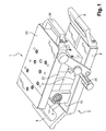
図1から図5は、上部1および底部2を備える本発明の射出成形具を示しており、これらの部分は、ピン3を中心に互いに対して枢動するように装着される。
1 to 5 show an injection molding tool according to the invention with a top 1 and a
より具体的には、底部2は、略矩形の形状の空洞ブロック4を備え、この空洞ブロック4は、図4および図5により明確に見られ得るように、その中に形成された空洞5および射出チャネル6を有し、同様に矩形状である縦長の平面の底部プレート8上にねじ7によって装着される。プレート8の2つの対向する端部には、ハンドル9が取り付けられる。プレート8はまた、長手方向の中央平面の両側に配置され、ピン3が中に装着されるU字形金具を形成する2つの横方向の耳金10も有する。より具体的には、ピン3は、耳金10内に装着された2つの玉軸受11によって案内され、上述された中央平面に対して直角である。
More specifically, the
底部2は、成形された部品を押し出す手段を有し、前記手段は、枢動ピン3上に端部が装着された第1の部分13と、第1の部分13に対してほぼ直角であり、湾曲形状の第1および第2のエジェクタ15および16がそこから延びる第2の部分14とを有する略L字状の支持体12を備える。第1のエジェクタ15は、第2の部分14の自由端部から延び、一方で第2のエジェクタ16は、第1のエジェクタ15と第1の部分13の間を延びる。より具体的には、エジェクタ15および16は、枢動ピン3上に心出しされた円形の弓形状のものである。押し出し手段は、上述された中央平面内に延びる。
The
底部空洞ブロック4は、エジェクタの形状と相補的な形状のものであり、エジェクタを通過させる2つの湾曲した開口部を有し、この開口部は、底部の空ゾーン17に至る(図2)。空ゾーンは、湾曲した開口部と一緒になって、押し出し手段が所定の角度範囲内で枢動することを可能にし、これは、以下でより詳細に説明される。
The
カム18が、プレート8内の開口部19内の押し出し手段のための支持体12の下方に収容され、カム18は、プレート8を貫通して延び、ハンドル20に取り付けられた端部を有するロッドに接続される。したがってハンドル20を回転させることにより、カム18は、プレート8の内側に完全に受け入れられる成形位置と、プレート8から突出し、支持体14の底面を押さえ付けてピン3を中心に枢動させられる押し出し位置との間で移動され得るように回転する。
A
押し出し手段は次いで、エジェクタ15および16が空洞5の外側にあり、空洞ブロック内にすべて収容される成形位置(図2および図4)と、エジェクタが空洞の内側で上方に突出する押し出し位置(図3および図5)との間で移動される。
The extrusion means then has a molding position (FIGS. 2 and 4) in which the
射出成形具の上部1は、同じようにして、空洞22が中に形成され、上部プレート23に締め付けられた空洞ブロック21を含む。上部プレート23は、プレート23の長手方向の中央平面の両側に配置され、ピン3上に装着されたU字形金具を形成する、2つの耳金24を有する。より具体的には、上部プレート23の各耳金24は、押し出し手段の支持体12の第1の部分13と、底部プレート8の耳金10の一方との間に装着される。
The upper part 1 of the injection molding tool includes a
枢動ピン3から遠位にある上部プレート23の端部には、ハンドル25が取り付けられる。
A
続いて、ブレード型26をろうから成形する方法をより詳細に説明する。
Next, a method for forming the
型26が冷却回路などの中空部分を含むとき、セラミックコア(図示せず)が底部空洞ブロック4の空洞5内に装着され、コアは、知られている方法で、当接によって配置され押さえねじ27によって保持されることが可能である。
When the
次いで射出成形具が閉じられ、すなわち上部および底部1および2が、2つの空洞ブロック21および4、したがって2つの空洞22および5も重ね合わせるように枢動される。互いに向かい合って位置しているときの空洞5および22によって画定される形状は、成形される対象の部品26に与えられるべき形状に対応する。特に、空洞5および22は、エアホイルおよびプラットフォームを備えるブレードの形状を画定する。少なくとも底部空洞ブロック4内の空洞5によって形成されるゾーンに関すると、プラットフォームは、湾曲し、枢動ピン3上で心出しされたほぼ円弧の形態である断面を有する形状を有している。
The injection molding tool is then closed, i.e. the top and
次いでプレス機(図示せず)が、プレート8および23の外面の各々を押し付け、ろうが、射出チャネル6を介して空洞5および22内に射出され、次いで冷却されて固化し、ろうブレード型26を形成する(図2および図3)。
A press (not shown) then presses each of the outer surfaces of the
射出成形具は次いで、上部をピンを中心に枢動させることによって開かれる(図2)。 The injection molding tool is then opened by pivoting the top about the pin (FIG. 2).
ろう型26を底部空洞ブロック4の空洞5から押し出すために、ハンドル20が、カム18を枢動させるように作動され、それによって押し出し手段を枢動させる。エジェクタ15および16は次いで、プラットフォームの形状、より正確には空洞5から引き出される対象のゾーンの形状に対応する形状のそれぞれの曲線のある通路に沿って移動する。
In order to push the
これは、プラットフォームのあらゆる損傷または変形を回避する働きをする。これにより、上記で説明された方法を用いてロストワックス鋳造によって得られたブレードが、仕様と適合することが保証される。 This serves to avoid any damage or deformation of the platform. This ensures that the blades obtained by lost wax casting using the method described above meet the specifications.
射出成形具は、ろう型26を成形するように本明細書で説明されてきたが、同じ技術的問題を解決するために、すなわち部品が押し出されるときに損傷を回避するために他のタイプの部品を成形するために使用され得る。
Although the injection molding tool has been described herein to mold the
Claims (7)
エジェクタ(15、16)が、湾曲した形状であり、空洞(5)から引き出される対象の成形された部品(26)の一部分の形状に対応する形状の、当該エジェクタ(15、16)の形状に適合する湾曲した通路を介してその2つの位置の間を移動するように案内されることを特徴とする、工具。 The cavity (5, 22) is a tool for injection molding a part (26) comprising two cavity blocks (4, 21) formed in each cavity (5, 22). In order to extrude the molded part into at least one of the hollow blocks (4), the shape corresponds to the shape of the part (26) to be molded when (4, 21) are overlaid. Extruding means comprising at least one ejector (15, 16) is attached, the at least one ejector (15, 16) being located in a molding position where it lies outside the corresponding cavity (5) and this is the cavity (5 ) A tool that is movable between an extruding position protruding into the tool,
The ejector (15, 16) has a curved shape, corresponding to the shape of a portion of the molded part (26) to be pulled out of the cavity (5), to the shape of the ejector (15, 16). A tool characterized in that it is guided to move between its two positions via a matching curved path.
Applications Claiming Priority (3)
| Application Number | Priority Date | Filing Date | Title |
|---|---|---|---|
| FR1053665 | 2010-05-11 | ||
| FR1053665A FR2959947B1 (en) | 2010-05-11 | 2010-05-11 | TOOLING INJECTION OF A PIECE |
| PCT/FR2011/051047 WO2011141674A1 (en) | 2010-05-11 | 2011-05-10 | Equipment for injecting a part |
Publications (2)
| Publication Number | Publication Date |
|---|---|
| JP2013526409A JP2013526409A (en) | 2013-06-24 |
| JP5801879B2 true JP5801879B2 (en) | 2015-10-28 |
Family
ID=43126912
Family Applications (1)
| Application Number | Title | Priority Date | Filing Date |
|---|---|---|---|
| JP2013509599A Active JP5801879B2 (en) | 2010-05-11 | 2011-05-10 | Tools for injection molding parts |
Country Status (11)
| Country | Link |
|---|---|
| US (1) | US8747099B2 (en) |
| EP (1) | EP2569117B1 (en) |
| JP (1) | JP5801879B2 (en) |
| KR (1) | KR101868641B1 (en) |
| CN (1) | CN102892530B (en) |
| BR (1) | BR112012025400B1 (en) |
| CA (1) | CA2795473C (en) |
| FR (1) | FR2959947B1 (en) |
| RU (1) | RU2559602C2 (en) |
| WO (1) | WO2011141674A1 (en) |
| ZA (1) | ZA201208140B (en) |
Families Citing this family (5)
| Publication number | Priority date | Publication date | Assignee | Title |
|---|---|---|---|---|
| CN104226899B (en) * | 2013-06-09 | 2016-03-30 | 北汽福田汽车股份有限公司 | The preparation method of diel cam evaporative pattern |
| CN106738557A (en) * | 2017-03-22 | 2017-05-31 | 昆山市三建模具机械有限公司 | A kind of refrigerator door liner shaping mould |
| CN113560489A (en) * | 2021-06-15 | 2021-10-29 | 季华实验室 | Turbine blade wax pattern ejection mechanism and mold |
| CN113732244B (en) * | 2021-08-09 | 2022-11-29 | 季华实验室 | Turbine blade wax pattern automatic ejection mechanism |
| CN113976821A (en) * | 2021-09-24 | 2022-01-28 | 季华实验室 | Automatic ejection mechanism for wax pattern of large turbine blade |
Family Cites Families (28)
| Publication number | Priority date | Publication date | Assignee | Title |
|---|---|---|---|---|
| US3545718A (en) * | 1968-02-01 | 1970-12-08 | Continental Oil Co | Removable mold core |
| US3632277A (en) * | 1968-09-05 | 1972-01-04 | Nibco | Method and apparatus for molding elbows and the like |
| US3930777A (en) * | 1974-12-11 | 1976-01-06 | Ramsey William C | Plastic u-shaped return conduit and apparatus and method for molding the same |
| DE7535944U (en) * | 1975-11-12 | 1976-03-11 | Fa. Adolf Hottinger, 6800 Mannheim | TOOL CARRIERS FOR SINGLE OR MULTI-STATION PLANTS IN THE FOUNDRY AND PLASTICS TECHNOLOGY |
| EP0013511A1 (en) * | 1979-01-03 | 1980-07-23 | Maurice Henry King | A method of making a die member |
| JPS59107762A (en) * | 1982-12-13 | 1984-06-22 | Akada Kanagata Seisakusho:Kk | Injection mold |
| JPH02219621A (en) * | 1989-02-21 | 1990-09-03 | Hitachi Lighting Ltd | Mold structure for treating undercut in injection mold |
| JP2617359B2 (en) * | 1989-09-22 | 1997-06-04 | 松下電工株式会社 | How to remove molded products |
| SU1731420A1 (en) * | 1990-03-20 | 1992-05-07 | Харьковский Филиал Центрального Научно-Исследовательского Технологического Института | Casting pattern mould |
| US5204046A (en) * | 1991-10-15 | 1993-04-20 | Callaway Golf Company | Wax pattern molding process |
| US5773048A (en) * | 1995-08-07 | 1998-06-30 | Ramsey; William C. | Retainer for injection molding machine components |
| KR19980027071U (en) * | 1996-11-14 | 1998-08-05 | 박병재 | Driving control device for persons with disabilities in cars |
| EP0950495B1 (en) * | 1997-09-16 | 2001-06-13 | IFW MANFRED OTTE GESELLSCHAFT m.b.H. & Co. KG | Mould for bent pipes |
| US5983978A (en) * | 1997-09-30 | 1999-11-16 | Thixomat, Inc. | Thermal shock resistant apparatus for molding thixotropic materials |
| DE19810032A1 (en) * | 1998-03-09 | 1999-09-16 | Acheson Ind Inc | Method and device for preparing the mold walls of a mold for primary shaping or shaping for the next molding cycle, spray element with centrifugal atomization and air guidance and use of such a spray element for spraying essentially solvent-free mold wall treatment agents |
| US7153125B2 (en) * | 2000-01-19 | 2006-12-26 | Rain Bird Corporation | Molded plastic elbow |
| JP2001269762A (en) * | 2000-03-28 | 2001-10-02 | Matsushita Electric Ind Co Ltd | Metal injection-molding device |
| US6399006B1 (en) * | 2000-06-08 | 2002-06-04 | Entegris, Inc. | Process and apparatus for molding polymer sweep fittings |
| US6505678B2 (en) * | 2001-04-17 | 2003-01-14 | Howmet Research Corporation | Ceramic core with locators and method |
| US20030015308A1 (en) * | 2001-07-23 | 2003-01-23 | Fosaaen Ken E. | Core and pattern manufacture for investment casting |
| JP2003103356A (en) * | 2001-09-27 | 2003-04-08 | Hoei Kogyo Kk | Apparatus and method for casting forged material |
| US7238839B2 (en) * | 2004-10-07 | 2007-07-03 | Divi's Laboratories Limited | Process for the resolution of racemic (R,S) -5-(2-(2-(2- ethoxyphenoxy) ethylamino)Propyl)-2-methoxybenzene sulfonamide (tamsulosin), its novel R and S isomers and their salts and processes for their preparation |
| KR100724244B1 (en) * | 2006-01-25 | 2007-05-31 | 엘에스전선 주식회사 | Clamping device of injection molding machine having molding ejecting device |
| FR2914871B1 (en) * | 2007-04-11 | 2009-07-10 | Snecma Sa | TOOLS FOR THE MANUFACTURE OF CERAMIC FOUNDRY CORES FOR TURBOMACHINE BLADES |
| JP4492703B2 (en) * | 2008-01-11 | 2010-06-30 | 株式会社デンソー | Molding equipment |
| KR101000626B1 (en) * | 2008-08-26 | 2010-12-10 | 엘에스엠트론 주식회사 | Ejector for injection molding machine and moving plate including the same |
| JP5633739B2 (en) * | 2010-10-29 | 2014-12-03 | アイシン精機株式会社 | Impeller molding equipment |
| US8349240B2 (en) * | 2011-03-25 | 2013-01-08 | Honda Motor Co., Ltd. | Hidden parting line mold and hidden parting line molding technique using associated part removal device |
-
2010
- 2010-05-11 FR FR1053665A patent/FR2959947B1/en active Active
-
2011
- 2011-05-10 JP JP2013509599A patent/JP5801879B2/en active Active
- 2011-05-10 EP EP11725146.2A patent/EP2569117B1/en active Active
- 2011-05-10 WO PCT/FR2011/051047 patent/WO2011141674A1/en active Application Filing
- 2011-05-10 CA CA2795473A patent/CA2795473C/en active Active
- 2011-05-10 US US13/642,995 patent/US8747099B2/en active Active
- 2011-05-10 RU RU2012152948/02A patent/RU2559602C2/en active
- 2011-05-10 KR KR1020127032232A patent/KR101868641B1/en active IP Right Grant
- 2011-05-10 BR BR112012025400-6A patent/BR112012025400B1/en active IP Right Grant
- 2011-05-10 CN CN201180023811.8A patent/CN102892530B/en active Active
-
2012
- 2012-10-29 ZA ZA2012/08140A patent/ZA201208140B/en unknown
Also Published As
| Publication number | Publication date |
|---|---|
| CA2795473A1 (en) | 2011-11-17 |
| BR112012025400B1 (en) | 2018-02-06 |
| WO2011141674A1 (en) | 2011-11-17 |
| EP2569117A1 (en) | 2013-03-20 |
| CA2795473C (en) | 2017-08-22 |
| CN102892530A (en) | 2013-01-23 |
| ZA201208140B (en) | 2014-03-26 |
| US20130040015A1 (en) | 2013-02-14 |
| BR112012025400A2 (en) | 2016-07-05 |
| EP2569117B1 (en) | 2018-07-04 |
| JP2013526409A (en) | 2013-06-24 |
| CN102892530B (en) | 2014-11-19 |
| FR2959947A1 (en) | 2011-11-18 |
| RU2559602C2 (en) | 2015-08-10 |
| KR101868641B1 (en) | 2018-06-18 |
| KR20130103340A (en) | 2013-09-23 |
| FR2959947B1 (en) | 2014-03-14 |
| RU2012152948A (en) | 2014-06-20 |
| US8747099B2 (en) | 2014-06-10 |
Similar Documents
| Publication | Publication Date | Title |
|---|---|---|
| JP5801879B2 (en) | Tools for injection molding parts | |
| EP3429778B1 (en) | Method of manufacturing advanced features in a core for casting | |
| CN103990761B (en) | A kind of production method of hollow turbine vane with impact opening structure | |
| JP6033769B2 (en) | Equipment for injection molding parts | |
| JPH0563263B2 (en) | ||
| JPS6055207B2 (en) | Method of manufacturing a one-piece wax-type assembly | |
| CN107116183B (en) | Method for preparing complex hollow cavity casting by matching ceramic core and soluble core | |
| JP7421568B2 (en) | Devices and methods for removing at least one cooling element from an at least partially demolded cast part, Methods for introducing at least one cooling element into a mold core of a cast part mold, Cooling elements and castings parts | |
| CN210996310U (en) | Fired mold structure of valve body | |
| US9278388B2 (en) | Process for the manufacturing of a thin-walled article in metal | |
| CN111655396B (en) | Casting apparatus and method of using the same | |
| JP4076220B2 (en) | Die casting equipment | |
| JP4628349B2 (en) | Casting method and casting apparatus | |
| JP3087083B2 (en) | Graphite mold for plastic molding | |
| CN213082039U (en) | Illuminating lamp mould structure | |
| WO2005018852A1 (en) | Cast-iron thixocasting apparatus and method | |
| JPH09182936A (en) | Metallic mold for forming wax formed product for precision casting | |
| JP7441215B2 (en) | Methods and tools for manufacturing coils and manufactured coils | |
| KR20050115738A (en) | Menufacturing method for metal casting moulds | |
| JP4134180B2 (en) | Injection mold and injection molding method | |
| JP4757833B2 (en) | Mold apparatus, mounting method thereof and molding apparatus | |
| CN114210918A (en) | Combination method of thick rapid-forming pouring system and wax mold body and shell mold preparation method | |
| JP2006055868A (en) | Casting method and metallic mold for casting | |
| CN110681824A (en) | Fired mold structure of valve body and manufacturing method thereof | |
| JPH0683150U (en) | Extrusion member for die casting mold |
Legal Events
| Date | Code | Title | Description |
|---|---|---|---|
| A621 | Written request for application examination |
Free format text: JAPANESE INTERMEDIATE CODE: A621 Effective date: 20140422 |
|
| A977 | Report on retrieval |
Free format text: JAPANESE INTERMEDIATE CODE: A971007 Effective date: 20150318 |
|
| A131 | Notification of reasons for refusal |
Free format text: JAPANESE INTERMEDIATE CODE: A131 Effective date: 20150407 |
|
| A521 | Request for written amendment filed |
Free format text: JAPANESE INTERMEDIATE CODE: A523 Effective date: 20150707 |
|
| TRDD | Decision of grant or rejection written | ||
| A01 | Written decision to grant a patent or to grant a registration (utility model) |
Free format text: JAPANESE INTERMEDIATE CODE: A01 Effective date: 20150804 |
|
| A61 | First payment of annual fees (during grant procedure) |
Free format text: JAPANESE INTERMEDIATE CODE: A61 Effective date: 20150827 |
|
| R150 | Certificate of patent or registration of utility model |
Ref document number: 5801879 Country of ref document: JP Free format text: JAPANESE INTERMEDIATE CODE: R150 |
|
| R250 | Receipt of annual fees |
Free format text: JAPANESE INTERMEDIATE CODE: R250 |
|
| R250 | Receipt of annual fees |
Free format text: JAPANESE INTERMEDIATE CODE: R250 |
|
| R250 | Receipt of annual fees |
Free format text: JAPANESE INTERMEDIATE CODE: R250 |
|
| R250 | Receipt of annual fees |
Free format text: JAPANESE INTERMEDIATE CODE: R250 |
|
| R250 | Receipt of annual fees |
Free format text: JAPANESE INTERMEDIATE CODE: R250 |
|
| R250 | Receipt of annual fees |
Free format text: JAPANESE INTERMEDIATE CODE: R250 |