JP5800265B2 - Demolding during manufacture of ophthalmic lens mold assemblies - Google Patents
Demolding during manufacture of ophthalmic lens mold assemblies Download PDFInfo
- Publication number
- JP5800265B2 JP5800265B2 JP2012527883A JP2012527883A JP5800265B2 JP 5800265 B2 JP5800265 B2 JP 5800265B2 JP 2012527883 A JP2012527883 A JP 2012527883A JP 2012527883 A JP2012527883 A JP 2012527883A JP 5800265 B2 JP5800265 B2 JP 5800265B2
- Authority
- JP
- Japan
- Prior art keywords
- mold
- lens
- puncher
- mold part
- assembly
- Prior art date
- Legal status (The legal status is an assumption and is not a legal conclusion. Google has not performed a legal analysis and makes no representation as to the accuracy of the status listed.)
- Active
Links
Images


Classifications
-
- B—PERFORMING OPERATIONS; TRANSPORTING
- B29—WORKING OF PLASTICS; WORKING OF SUBSTANCES IN A PLASTIC STATE IN GENERAL
- B29C—SHAPING OR JOINING OF PLASTICS; SHAPING OF MATERIAL IN A PLASTIC STATE, NOT OTHERWISE PROVIDED FOR; AFTER-TREATMENT OF THE SHAPED PRODUCTS, e.g. REPAIRING
- B29C33/00—Moulds or cores; Details thereof or accessories therefor
- B29C33/44—Moulds or cores; Details thereof or accessories therefor with means for, or specially constructed to facilitate, the removal of articles, e.g. of undercut articles
-
- B—PERFORMING OPERATIONS; TRANSPORTING
- B29—WORKING OF PLASTICS; WORKING OF SUBSTANCES IN A PLASTIC STATE IN GENERAL
- B29D—PRODUCING PARTICULAR ARTICLES FROM PLASTICS OR FROM SUBSTANCES IN A PLASTIC STATE
- B29D11/00—Producing optical elements, e.g. lenses or prisms
- B29D11/00009—Production of simple or compound lenses
- B29D11/00038—Production of contact lenses
- B29D11/00125—Auxiliary operations, e.g. removing oxygen from the mould, conveying moulds from a storage to the production line in an inert atmosphere
- B29D11/00192—Demoulding, e.g. separating lenses from mould halves
- B29D11/00221—Demoulding, e.g. separating lenses from mould halves using prying means
-
- B—PERFORMING OPERATIONS; TRANSPORTING
- B29—WORKING OF PLASTICS; WORKING OF SUBSTANCES IN A PLASTIC STATE IN GENERAL
- B29C—SHAPING OR JOINING OF PLASTICS; SHAPING OF MATERIAL IN A PLASTIC STATE, NOT OTHERWISE PROVIDED FOR; AFTER-TREATMENT OF THE SHAPED PRODUCTS, e.g. REPAIRING
- B29C33/00—Moulds or cores; Details thereof or accessories therefor
- B29C33/44—Moulds or cores; Details thereof or accessories therefor with means for, or specially constructed to facilitate, the removal of articles, e.g. of undercut articles
- B29C33/48—Moulds or cores; Details thereof or accessories therefor with means for, or specially constructed to facilitate, the removal of articles, e.g. of undercut articles with means for collapsing or disassembling
-
- B—PERFORMING OPERATIONS; TRANSPORTING
- B29—WORKING OF PLASTICS; WORKING OF SUBSTANCES IN A PLASTIC STATE IN GENERAL
- B29C—SHAPING OR JOINING OF PLASTICS; SHAPING OF MATERIAL IN A PLASTIC STATE, NOT OTHERWISE PROVIDED FOR; AFTER-TREATMENT OF THE SHAPED PRODUCTS, e.g. REPAIRING
- B29C37/00—Component parts, details, accessories or auxiliary operations, not covered by group B29C33/00 or B29C35/00
- B29C37/0003—Discharging moulded articles from the mould
- B29C37/0007—Discharging moulded articles from the mould using means operable from outside the mould for moving between mould parts, e.g. robots
-
- B—PERFORMING OPERATIONS; TRANSPORTING
- B29—WORKING OF PLASTICS; WORKING OF SUBSTANCES IN A PLASTIC STATE IN GENERAL
- B29D—PRODUCING PARTICULAR ARTICLES FROM PLASTICS OR FROM SUBSTANCES IN A PLASTIC STATE
- B29D11/00—Producing optical elements, e.g. lenses or prisms
Landscapes
- Engineering & Computer Science (AREA)
- Mechanical Engineering (AREA)
- Health & Medical Sciences (AREA)
- Manufacturing & Machinery (AREA)
- Ophthalmology & Optometry (AREA)
- Robotics (AREA)
- Moulds For Moulding Plastics Or The Like (AREA)
- Eyeglasses (AREA)
- Casting Or Compression Moulding Of Plastics Or The Like (AREA)
Description
本発明は、オフサルミックレンズ、例えばコンタクトレンズの製造に用いられる方法、装置及びシステムに関する。特に、2つのモールド半部を互いに分離するためのパンチャを用いてオフサルミックレンズモールド組立体を脱型する方法、装置及びシステムが開示される。 The present invention relates to methods, apparatus and systems used in the manufacture of ophthalmic lenses, such as contact lenses. In particular, a method, apparatus and system for demolding an ophthalmic lens mold assembly using a puncher for separating two mold halves from each other is disclosed.
〔関連出願の説明〕
本願は、2009年8月31日に出願された通常の米国特許仮出願第61/238,565号であり、この米国特許仮出願を参照により引用し、その記載内容を本明細書の一部とする。
[Description of related applications]
The present application is an ordinary US provisional application 61 / 238,565 filed on August 31, 2009, and this US provisional application is incorporated by reference, and the contents thereof are incorporated herein by reference. And
注型コンタクトレンズ、例えばヒドロゲル及びシリコーンヒドロゲルコンタクトレンズの製造に用いられる射出成形オフサルミックモールド組立体は、典型的には、レンズをモールド組立体内で形成した後、雄型モールド半部と雌型モールド半部を開き又は分離する脱型ステップを必要とする。形成されたレンズは、モールド半部のうちの一方に取り付けられたままであり、次に、これから分離されて更に加工される。 Injection molded ophthalmic mold assemblies used in the manufacture of cast contact lenses, such as hydrogel and silicone hydrogel contact lenses, typically have male mold halves and female molds after the lenses are formed in the mold assembly. A demolding step is required to open or separate the mold halves. The formed lens remains attached to one of the mold halves and is then separated from it and further processed.
2つのモールド半部を分離する多くの技術が当該技術分野において知られている。1つの脱型技術は、キャップ除去(decapping)と呼ばれており、このキャップ除去では、2つのモールド区分を物理的に分離する機械的装置が必要である。キャップ除去における一方式は、横力をモールド組立体の外周部に加えて雄型モールドか雌型モールドかのいずれかに変形を生じさせ、次にこれらモールドを互いに保持している密封力を失わせることである。もう1つの手法は、1つ又は2つ以上のウェッジを用いて2つのモールド区分相互間に隙間をあけてこれらモールドをこじって互いに離すことである。 Many techniques for separating two mold halves are known in the art. One demolding technique is referred to as decapping, which requires a mechanical device that physically separates the two mold sections. One method of removing the cap is to apply lateral force to the outer periphery of the mold assembly, causing deformation in either the male mold or the female mold, and then losing the sealing force that holds the molds together. It is to let you. Another approach is to use one or more wedges to open the gap between the two mold sections and pry the molds apart from each other.
成形オフサルミックレンズ、例えばコンタクトレンズを製造する新規な方法、装置及びシステムが開示される。本発明の方法は、オフサルミックレンズ脱型装置を利用してオフサルミックレンズモールド組立体のモールド部分を互いに分離し、成形オフサルミックレンズをモールド部分のうちの一方から取り出して更に加工することができるようにする。本発明の方法、装置及びシステムは、打ち抜き技術を用いて雄型モールド部分を雌型モールド部分から分離することによりレンズモールド組立体を脱型するのに有用である。理解できるように、雄型モールド部分は、オフサルミックレンズの後面に対応した凸状の成形面を有し、したがって、この凸状成形面を後面モールドと呼ぶことができ、雌型モールド部分は、オフサルミックレンズの前面に対応した凹状の成形面を有し、したがって、この凹状成形面を前面モールドと呼ぶことができる。本発明の方法、装置及びシステムでは、脱型プロセスにおいて、一方のモールド部分のモールド層を突き通し、次にもう1つの成形部分の成形層を押して2つのモールド部分を互いに分離することによりレンズモールド組立体を脱型することができる。 Disclosed are novel methods, apparatus and systems for producing molded ophthalmic lenses, such as contact lenses. The method of the present invention uses an ophthalmic lens demolding device to separate the mold parts of the ophthalmic lens mold assembly from each other, and removes the molded ophthalmic lens from one of the mold parts for further processing. To be able to. The method, apparatus and system of the present invention are useful for demolding a lens mold assembly by separating the male mold part from the female mold part using stamping techniques. As can be seen, the male mold part has a convex molding surface corresponding to the rear surface of the ophthalmic lens, so this convex molding surface can be referred to as a rear mold, and the female mold part is And having a concave molding surface corresponding to the front surface of the ophthalmic lens. Therefore, this concave molding surface can be called a front mold. In the method, apparatus and system of the present invention, in the demolding process, the lens mold is pierced through the mold layer of one mold part, and then the mold layer of another mold part is pushed to separate the two mold parts from each other. The assembly can be removed.
本明細書において開示する方法は、第1のモールド部分及び第2のモールド部分を含むレンズモールド組立体をパンチャの下に配置するステップを有する方法を含む。レンズモールド組立体は、成形オフサルミックレンズ、例えば成形コンタクトレンズを収容する。パンチャは、少なくとも1本のパンチピンを有する。少なくとも1つのパンチピンは先端部を有する。本発明の方法では、高い高さ位置においてパンチャをレンズモールド組立体により構成された筒体内で軸線に沿って移動させ、第1のモールドの表面層を突き通す。次に、この方法では、第1のモールド部分を打ち抜いた後、第2のモールド部分の表面層を押して第2のモールド部分を第1のモールド部分から分離する。 The method disclosed herein includes a method comprising placing a lens mold assembly including a first mold portion and a second mold portion under a puncher. The lens mold assembly houses a molded ophthalmic lens, such as a molded contact lens. The puncher has at least one punch pin. At least one punch pin has a tip. In the method of the present invention, the puncher is moved along the axis in the cylindrical body constituted by the lens mold assembly at the high height position, and penetrates the surface layer of the first mold. Next, in this method, after punching out the first mold part, the surface layer of the second mold part is pressed to separate the second mold part from the first mold part.
本明細書において開示する方法のもう1つの例は、パンチ本体の遠位端部を越えて延びる少なくとも1本のパンチピンを有するパンチャをレンズモールド部分を抜き取るストリッパ装置の開口部を通って移動させる方法を含む。この方法では、更に、パンチャがレンズモールド組立体を支持するよう構成された支持パレットに達する前にこの移動ステップを停止させ、次に、パンチャをパンチャがストリッパ装置の開口部を通って戻らなければならないようにする位置まで戻す。 Another example of a method disclosed herein is a method of moving a puncher having at least one punch pin extending beyond a distal end of a punch body through an opening in a stripper device that extracts a lens mold portion. including. The method further stops the moving step before the puncher reaches a support pallet configured to support the lens mold assembly, and then the puncher must be returned through the opening of the stripper device. Return to the position where you want to prevent it.
本発明の更に別の特徴は、パンチボアを備えたパンチ本体を含むパンチャを有するオフサルミックレンズ脱型装置に関する。ピン先端部を含むパンチピンがパンチボア内に配置され、ピン先端部は、パンチ本体の遠位端部を越えて延びるようになっている。脱型装置は、脱型されるべき2部品構成型モールド組立体の少なくとも一方の部分を支持するよう構成された支持プレートを更に有し、パンチピンは、脱型のためにレンズモールド組立体のモールド層を突き通すよう寸法決めされると共に十分な力で動かされる。 Yet another feature of the present invention relates to an ophthalmic lens demolding apparatus having a puncher that includes a punch body with a punch bore. A punch pin including a pin tip is disposed in the punch bore, the pin tip extending beyond the distal end of the punch body. The demolding device further comprises a support plate configured to support at least one portion of the two-part mold assembly to be demolded, and the punch pin is a mold of the lens mold assembly for demolding. It is sized to penetrate the layer and moved with sufficient force.
別の例では、脱型システム用のパンチャが提供される。 In another example, a puncher for a demolding system is provided.
本発明の追加の特徴は、1本又は2本以上のパンチピンを用いてモールド部分のフランジ層を打ち抜くパンチャである。 An additional feature of the present invention is a puncher that punches out the flange layer of the mold portion using one or more punch pins.
さらに別の例では、ストリッパコラムがパンチャと共に用いられ、パンチャは、ストリッパコラムと一緒に動くことができると共にストリッパコラムに対して動くことができる。 In yet another example, a stripper column is used with the puncher, which can move with and with respect to the stripper column.
本発明の追加の例は、本明細書において説明するオフサルミックレンズ脱型装置の製造に関する。 An additional example of the present invention relates to the manufacture of the ophthalmic lens demolding device described herein.
本発明の種々の例が以下の詳細な説明及び特許請求の範囲に詳細に記載されている。本明細書において説明するどの特徴であっても又は特徴のどのような組み合わせでもあっても、かかる任意の組み合わせに含まれる特徴が前後関係、本明細書及び当業者の通常の知識から明らかであるように相互に矛盾しない限り、本発明の範囲に含まれる。加うるに、任意の特徴又は特徴の任意の組み合わせが、本発明の任意の例から具体的に除かれる場合がある。 Various examples of the invention are described in detail in the following detailed description and claims. Whatever feature or combination of features described in this specification is, the features included in any such combination are apparent from the context, the specification and the ordinary knowledge of those skilled in the art. As long as they do not contradict each other, they are included in the scope of the present invention. In addition, any feature or combination of features may be specifically excluded from any example of the present invention.
添付の図面と関連して以下に与えられる詳細な説明は、本発明に従って提供されるオフサルミックレンズモールド組立体脱型装置の例の説明を目的としており、本発明を構成し又は利用することができる形態だけを表すものではない。以下の詳細な説明は、図示の例と関連して脱型装置を構成してこれら脱型装置を用いる特徴及びステップを記載している。しかしながら、同一又は同等の機能及び構造は、これ又本発明の精神及び範囲に含まれるようになった別の例によって達成できることは理解されるべきである。 The detailed description provided below in connection with the accompanying drawings is intended to illustrate an example of an ophthalmic lens mold assembly demolding apparatus provided in accordance with the present invention and to constitute or utilize the present invention. It does not represent only the form that can be. The following detailed description describes the features and steps of configuring a mold release device and using these mold release devices in conjunction with the illustrated example. However, it is to be understood that the same or equivalent function and structure may be achieved by other examples which also come within the spirit and scope of the present invention.
図1及び図2は、オフサルミックレンズモールド組立体を脱型する本発明の方法、システム及び装置に用いられる代表的なオフサルミックレンズモールド組立体10を概略的に示している。モールド組立体10は、雄型モールド部分又は半部12及び雌型モールド部分又は半部14を含み、このモールド組立体は、米国特許第6,405,993号の要旨であり、この米国特許を参照により引用し、その記載内容全体を本明細書の一部とする。広義に言って、雄型モールド部分12は、凸状レンズ形成面16、機械的係合領域18、環状面領域又は雌型フランジ領域20及び軸方向端部22aを備えたスカート区分22(これは、リム又はリブと呼ばれる場合がある)を有する。
1 and 2 schematically illustrate an exemplary ophthalmic
雌型モールド部分14は、凹状レンズ形成面24、オーバーフロー及び機械的係合領域26、環状面領域又は雌型フランジ領域28及び環状面領域28により第1の軸方向端部32aを備えた第1のリブ又はリム領域32及び第2の軸方向端部34aを備えた第2のリブ又はリム領域34に至る円筒形壁30を有している。
The
雄型及び雌型モールド部分は、射出成形によりポリプロピレンから作られるのが良く、モールド組立体10は、両方のモールド半部の中心を通る軸線を備えたモールド中心を有しているものと理解される。射出成形に適した他の熱可塑性樹脂、例えばポリスチレン樹脂を用いることができる。
The male and female mold parts may be made from polypropylene by injection molding and the
本発明のオフサルミックレンズモールド組立体脱型装置及び関連方法に有用なオフサルミックレンズモールド組立体をオフサルミックレンズの注型又は静的成形に用いることができる。便宜上、本発明の開示は、オフサルミックレンズの例示としてコンタクトレンズに関する。 The ophthalmic lens mold assembly useful for the ophthalmic lens mold assembly demolding apparatus and related method of the present invention can be used for casting or static molding of ophthalmic lenses. For convenience, the present disclosure relates to contact lenses as examples of ophthalmic lenses.
図1のモールド組立体の部分断面図であり、雌型モールド部分14に係合した雄型モールド部分12を示す図2を参照すると、凸状レンズ形成面16及び凹状レンズ形成面24は、一緒になって、レンズ形成凹部又はレンズ形成キャビティ36を構成している。オフサルミックレンズ本体を注型する際、先ず最初に、重合性配合物又は調合物を雌型モールド部分14の凹状レンズ形成面に付着させる。重合性配合物は、重合オフサルミックレンズ又はコンタクトレンズを形成するのに適した反応性化合物を含む。或る特定の例では、レンズは、ヒドロゲルレンズである(例えば、これらレンズは、平衡状態で水を吸収すると共にこれを保持することができる)。追加の例では、レンズは、シリコーンヒドロゲルレンズ(例えば、平衡状態で水を吸収すると共にこれを保持することができるシリコーン含有レンズ)である。配合物は、追加の成分、例えば重合開始剤、架橋剤、紫外線遮断剤、着色剤、湿潤剤等及びこれらの組み合わせを更に含む場合がある。重合性配合物を雌型モールド部分14上に配置した後、次に、雄型モールド部分12を雌型モールド部分14に係合させて十分な量の重合性配合物をレンズ形成凹部36内に捕捉する。
FIG. 2 is a partial cross-sectional view of the mold assembly of FIG. 1 and shows the
重合性配合物を熱又は光、例えばUV光に当てることにより、重合反応が開始し、重合性配合物は、反応してレンズ形成凹部36内にポリマーレンズ本体を形成する。かくして、モールド組立体内に形成されたポリマーレンズ本体は、シリコーンヒドロゲル接触レンズ本体を含むヒドロゲルコンタクトレンズ本体を構成することができる。雄型及び雌型モールド部分12,14は、今や、レンズ形成凹部36内に形成されたオフサルミックレンズ本体を露出させるよういつでも脱型可能な状態にある。
By subjecting the polymerizable formulation to heat or light, such as UV light, a polymerization reaction is initiated and the polymerizable formulation reacts to form a polymer lens body in the
2つのオーバーフローキャビティ38,40に対して半径方向外方にそれぞれ雄型及び雌型部分の2つの環状領域又はフランジ20,28が設けられている。図2において雌型フランジ28に付けられている矢印42及び雄型フランジ20に付けられている矢印の上方の対応フランジ領域43によって示されているように、雄型モールド部分12を雌型モールド部分14から分離するための分離領域42が設けられており、これについては、以下において更に説明する。以下に更に説明する理由により、分離領域42のところの1つ又は複数の分離箇所を1つ又は複数の標的又は突き通し箇所52と呼ぶ場合があり、対応のフランジ領域43を衝撃箇所又は押し箇所と呼ぶ場合がある。変形例として、分離領域42及び1つ又は複数の標的又は突き通し箇所52は、雄型モールドフランジ20上の箇所であっても良く、衝撃箇所又は押し箇所は、雌型モールドフランジ28(図示せず)上の箇所であっても良い。各モールド組立体を分離するのに用いられる突き通しの回数に応じて、1組又は2組以上、例えば3つ又は4つの組をなす突き通し及び衝撃箇所52,43が衝撃領域42に沿って設けられるのが良い。
Two annular regions or
図3は、全体が符号44で示されたオフサルミックレンズモールド組立体脱型装置を概略的に示している。組立体又は脱型装置44は、一度に複数個、例えば2つ又は3つ以上、例えば6個のモールド組立体10を同時に脱型し、或いは、組立体内に設置され又は組立体内で作動されるパンチャの数を1つに制限することにより又は脱型のためにたった1つのモールド組立体10を装填することにより一度に1つしか脱型しないよう構成される。一例では、組立体44は、脱型のために複数個のレンズモールド組立体10を受け入れる装填パレット又はプレート46、突き通し作業に続き、モールド部分又はモールド半部を抜き取るストリッパプレート48及び複数個のモールド組立体の分離領域42を突き通してモールドを互いに分離する複数個のパンチャ50を有し、これについては以下に更に説明する。特定の例では、複数個のパンチャ50は、ヘッダ51に取り付けられ、ヘッダ51は、ヘッダ及びパンチャをy軸に沿って動かす単軸可動キャリジ(図示せず)に連結されている。キャリジは、軸線に沿って動いてパンチャを動かし、これらをモールド組立体に当て、その後、新たなモールド組立体を装填する位置に戻る任意の数の従来型装置を具体化したものであって良い。例えば、キャリジは、単軸ロボットアーム、ラック・ピニオン歯車駆動システム、加圧ガス又は流体を用いる作動シリンダ駆動システム及びヘッダを制動すると共に/或いは装填位置に戻す1つ又は2つ以上のばねを具体化することができる。単一の成形作業における複数個のパンチャ50又は1つのパンチャをひとまとめにパンチヘッダ53と呼ぶ場合がある。図3に示されているように、装填パレット又はプレート46は、雄型モールド部分12が雌型モールド部分14の下に位置した状態でレンズモールド組立体10を装填するよう構成されている。ただし、他の形態、例えば雌型モールド部分14を雄型モールド部分12の下に位置した状態での装填が可能である。
FIG. 3 schematically shows an ophthalmic lens mold assembly demolding apparatus generally designated 44. The assembly or demolding device 44 simultaneously demolds a plurality of, for example, two or more, for example six,
次に、図1及び図3に加えて図4を参照すると、複数個のモールド組立体10を脱型のために受け入れる装填パレット46の部分図が示されており、この装填パレットは、複数個の受け入れボア54を有している。ボア54の数は、好ましくは、用いられるべきパンチャ50の数及びそれ故に同時に脱型されるべきレンズモールドの数に一致している。図示のように、ボア54は、ボア直径を備えたボア開口部56と、ボア直径よりも小さいフランジ直径のフランジ周囲60を備えたフランジ58とを有している。フランジ周囲60は、パレット46を貫通して延びる貫通開口部62を構成している。図3に示されているように、使用の際、受け入れボア54は、モールド組立体を受け入れるよう構成されており、モールド組立体は、リブ軸方向端部22a,34aを有するモールド組立体の部分が先ず最初に受け入れボア54内に配置された状態で受け入れボア54内に配置される。かくして、図3及び図4に示されている例では、モールド組立体10は、いったん位置決めされると、その雌型モールド部分14の凸状外面64は、図3に示されているようにパンチャ50の方に差し向けられる。変形例として、受け入れボア54は、先ず最初にリブ軸方向端部32aから装填されるべきモールド組立体を受け入れるよう構成されても良い。
Referring now to FIG. 4 in addition to FIGS. 1 and 3, a partial view of a
再び図1及び図4を参照すると、雄型モールド部分12に設けられていて、全体として円筒形の構造のリブ22は、最大寸法方向に沿ってリブ軸方向端部22aのところで縁から縁まで測定したリブ直径66を有している。リブ直径66は、受け入れボア54のフランジ直径60よりも小さく、したがって、雄型モールド部分12を雌型モールド部分14から分離すると、以下に更に説明するように、雄型モールド部分は、装填パレット46の貫通開口部62を通って落下し、そして次の加工のために下に集められるようになる。変形例として、雄型モールド部分12は、雄型モールド部分を雌型モールド部分14に係合させると、リブスカート軸方向端部22aが雌型モールドの第2の軸方向端部34aの上方に延びるように寸法決めされたリブ22を有するよう設計されても良く、この場合、雄型モールド部分12のリブ直径66は、雌型モールド部分14の縁から縁まで測定した壁直径68よりも大きい。この例では、壁直径68は、受け入れボア54のフランジ直径60よりも小さく、したがって、雄型モールド部分12を雌型モールド部分14から分離すると、雌型モールド部分は、装填パレット46の貫通開口部62を通って落下し、次の加工のために下に集められるようになる。
Referring to FIGS. 1 and 4 again, the
図1〜図3に示されているように、円筒形の壁30は、同様に、最大寸法方向に沿って第2のリブ軸方向端部34aのところで縁から縁まで測定した壁直径68を有する。この壁直径68は、受け入れボア54のボア開口部56よりも小径であるが、フランジ開口部60よりも大径であり、したがって、モールド組立体10を受け入れボア(図3)内に配置すると、フランジ58によって支持されるのは雌型モールド部分14の第2の軸方向端部34であって、雄型モールド部分12のリブ軸方向端部22aではない。変形例として、上述した構成とは異なる構成のレンズモールド組立体の場合、装填パレット46のフランジ58によって支持されるのは、雄型モールド部分12の軸方向端部22aであっても良いが、雌型モールド部分14の軸方向端部ではない。一例では、装填パレット46は、硬質プラスチック材料で作られる。しかしながら、本発明の精神及び範囲から逸脱することなく、他の材料、例えばアルミニウム又は鋼を用いることができる。
1-3, the
装填パレット又はプレート46に脱型のために1つ又は2つ以上のモールド組立体10を装填する場合、このパレットを装填済みパレットと呼ぶ場合があり、かかる装填済みパレットは、以下に更に説明するように、パンチャ58によりいつでも作用を受けることができる状態にある。パレット46には手動でモールド組立体を装填することができ又は機械により、例えば、ピックアンドプレース式装置又は特別に設計された装填機械により装填しても良い。本発明の更に別の例では、コンベヤシステム(図示せず)が打ち抜きによりモールド半部を互いに分離するために複数個の装填済みパレットを一度に1つずつパンチヘッダ53の下に運搬するために使用されても良く、これについては以下において更に説明する。いったん突き通されると、コンベヤシステムは、使用済みパレットをどかして装填済みパレットを突き通しのために定位置に動かす。
When one or
かくして、本発明の一例は、貫通開口部を構成するフランジを備えた少なくとも1つの受け入れボアを有する組み合わせパレット及び内側リム及び外側リムを備えたモールド組立体を含むものとして理解され、この場合、内側リムではなく、外側リムがフランジによって支持されるよう受け入れボア内に位置決めされる。一例では、モールド組立体は、雌型モールド部分の凸状外面が貫通開口部から遠ざかる方向に面し又は向くよう受け入れボア内に位置決めされる。別の例では、モールド組立体は、2部品構成型モールド組立体を脱型するために2部品構成型モールド組立体の第1のフランジ層を打ち抜くパンチャの下に位置決めされ、これについては以下において更に説明する。 Thus, an example of the present invention is understood to include a combination pallet having at least one receiving bore with a flange defining a through opening and a mold assembly having an inner rim and an outer rim, in which case the inner rim The outer rim, not the rim, is positioned in the receiving bore so that it is supported by the flange. In one example, the mold assembly is positioned in the receiving bore such that the convex outer surface of the female mold portion faces or faces away from the through opening. In another example, the mold assembly is positioned under a puncher that punches the first flange layer of the two-part mold assembly to demold the two-part mold assembly, as described below. Further explanation will be given.
再び図3を参照すると、ストリッパプレート48は、装填パレット46と同様、複数個の貫通ボア70、例えば2つ若しくは3つ以上のボア又は装填パレット46の受け入れボア54に対応した数のボア又はパンチヘッダ53に取り付けられているパンチャ50の数と同数のボアを有する。図3に示されているように、貫通ボア70は各々、雌型モールド部分14の壁直径68よりも小さいがパンチャ50のパンチャ直径76よりも大きいボア直径74を備えたボア開口部72を有する。かくして、貫通ボア70は、パンチャ50がこの貫通ボアを通過するが、雌型モールド部分14の壁30を貫通することができないよう構成されている。使用中、以下に更に説明するように、パンチャ50は、貫通ボア70を通過して雄型モールド部分12を雌型モールド部分14から分離し、次に引っ込む。パンチャが引っ込んでいるとき、雌型モールド部分14は、パンチャと一緒に動き、ついには、雌型モールド部分は、貫通ボア70と雌型モールド部分14の壁直径68の相対的寸法に起因してストリッパプレート48に当たるようになる。次に、パンチャは、ストリッパプレートの上方のその装填又は幾分引っ込んだ位置に動き、その間、雄型モールド部分は、装填パレット46に向かって落下し、手動で又は収集若しくはすくい取り装置によって除去される。
Referring again to FIG. 3, the
一例では、ストリッパプレート48は、硬質プラスチック材料又は鋼で作られ、このストリッパプレートは、地面又は装填パレットに対し高さ方向に静止状態に保たれる。別の例では、ストリッパプレート48は、ヘッダ51を保持しているフレームに固定される。ストリッパプレート48は、雌型モールド部分14又は雄型モールド部分12を抜き取る装填パレット46の上方の定位置に固定されているが、ストリッパプレートは、モールド組立体又は装填済みパレットを掃除すると共に/或いは装填するために隙間を作る位置に出入りしても良い。この例では、ストリッパプレート48は、パンチヘッダ53を引っ込める前であって打ち抜き作業後に、複数個のパンチャ50の下の位置に動くよう構成されている。
In one example, the
本発明の別の例では、脱型プロセス中、雌型モールド部分14又は雄型モールド部分12は、パンチャ/ストリッパ組立体に関する必要性に応じて、適正な向きで窪み内に固定された状態で保持されるのが良く、パンチャ/ストリッパ組立体を窪みに嵌まり込んでいる状態の雌型モールド部分14又は雄型モールド部分12に接近するよう移動させるのが良く、その結果、ストリッパプレートは、脱型プロセス中、窪みに嵌まり込んでいる状態のモールド部分を固定位置に保持するようになる。脱型プロセス中、パンチャは、その前方位置と引っ込み位置との間で動き、窪みに嵌まり込んでいる状態のモールド部分を突き通し、第1のモールド部材と第2のモールド部材を互いに分離し(即ち、雄型モールド部分12を雌型モールド部分14から脱型し)、その間、窪みに嵌まり込んでいる状態のモールド部分は、ストリッパプレートと窪みとの間に保持されたその固定位置で不動状態のままである。
In another example of the present invention, during the demolding process, the
本発明の更に別の例では、複数個の個々のストリッパコラム78(図3に破線で示されている)が各パンチャ50の周りに設けられる。ストリッパコラム78は、雌型モールド部分14又は雄型モールド部分12を抜き取るストリッパプレート48の代替手段として使用可能である。一例では、ストリッパコラムは、パンチャ50に被せて設けられるハウジング外周部80を備えた円筒形ハウジングを有する。パンチャ50を円筒形ハウジング78に対して動かすことによりモールド組立体10を突き通して引っ込めた後、雌型モールド部分14又は雄型モールド部分12がハウジング78の開口部に引き当てられたとき、雌型モールド部分14又は雄型モールド部分12は、抜き取られる。ストリッパコラム78に関するそれ以上の説明は、図13及び図14を参照して以下において与えられる。
In yet another example of the present invention, a plurality of individual stripper columns 78 (shown in phantom in FIG. 3) are provided around each
かくして、本発明の一例は、ストリッパ装置48のボア開口部70及び装填パレット46の受け入れボア54と位置合わせされるパンチャを有する脱型組立体を有するものとして理解される。特定の一例では、雄型モールド部分及び雌型モールド部分を含むモールド組立体がストリッパ装置のボア開口部と装填プレートの受け入れ開口部との間にパンチによる脱型のために位置決めされる。別の例は、ボア開口部を有するストリッパ装置とボア開口部を有する装填パレットとの間に位置決めされるモールド組立体を有するものとして理解され、この場合、モールド組立体の雌型モールド部分14又は雄型モールド部分12は、ボア開口部のいずれも通って動くのが制限される。
Thus, an example of the present invention is understood as having a demolding assembly having a puncher aligned with the bore opening 70 of the
次に図5〜図10を参照すると、例示のパンチャ50が種々の図に示された状態で提供されている。最初に図7〜図10を参照すると、例示のパンチャ50は、パンチトップ又は上側84及びパンチボトム又は下側86を有し、パンチトップ及びパンチボトムは、金属材料、例えばアルミニウム、鋼又は鋼合金から注型され又は機械加工されるのが良い。パンチトップ84は、フランジ90及びソケット92を備えた本体88を有する。フランジ90は、ヘッダ51(図3)の表面と嵌合し又はこれに当接するよう構成され、ソケット92は、ヘッダから突き出たスタブ又はステム(図示せず)を受け入れるよう構成されている。本体88は、止めナットスタブに保持され又は変形例としてスタブと螺合されても良い。本体88は、工具又はレンチで掴んで回すための六角ナットの回し面と同様な回し面94を外部に有するのが良い。変形例として、本体88は、ヘッダに設けられているソケット中に突き出るスタブ又はステムを有しても良い。
Referring now to FIGS. 5-10, an
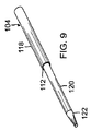
雄型ステム96が本体88の遠位端部98のところに設けられており、この雄型ステムは、パンチボトムに設けられている止めナット(図示せず)と係合可能なオプションとしての凹み箇所又は凹み領域100を有し、パンチボトムの止めナットは、図8を参照して以下に更に説明するようにパンチボトムをパッチトップに固定するために使用可能である。別の例では、雄型ステム96は、パンチトップ84とパンチボトム86の正確な位置合わせを可能にする押し出し設計のボスを有するのが良く、凹み領域100は、止めねじを用いて本体88を定位置に嵌めることができるようにする溝となる。かかる構成により、ピンの保守に必要な場合、パンチトップ84からのパンチボトム86の迅速な解除が可能になる。雄型ステム96は、複数本のパンチピン104を支持する肩102の遠位側に延び、パンチピン104は、上側ピン区分118、中央ピン区分120、これら部分を互いに隔てる段付き肩112及びテーパ付き又は切頭円錐形の頂部区分122を有する。ピンの頂部は、ピンの頂部が第1のモールド部材を突き通すことができるように構成されている。例えば、上述したように、先端部は、テーパしていても良く、丸形であっても良く、平坦な又は丸形の頂部を備えた真っ直ぐなボアを有しても良く、平坦な又は丸形の先端部を備えた状態でテーパしていても良いこと等である。頂部区分122は、ピンが図示すると共に以下に更に説明するように、雌型モールド部分14のフランジ区分28を突き通すことができるのに十分尖っており又は丸くなっているのが良い。変形例として、頂部区分122は、雄型モールド部分12のフランジ区分20を突き通すのに十分尖っており又は丸くなっていても良い。頂部区分122がモールド部分のフランジ区分を突き通すのに必要な頂部区分122の構成(例えば、必要な尖り付け又は丸み付けの量)は、当業者には理解されるように、例えばモールド部分に用いられる材料、コンタクトレンズ本体を成形するために用いられる重合性配合物、少なくとも1本のパンチピン104に加えられる力、パンチピン104の直径等のような要因で決まる。一例では、雄型ステム96は、パンチボトムに設けられたソケット106中への挿入を容易にするテーパ付きコーナ部を有する。
A
パンチボトム86は、パンチャ50(図5及び図6も又参照されたい)を形成するよう図10に示されているように複数本のパンチピン104を受け入れてパンチトップ84と嵌合するよう構成されている。一例では、パンチボトム86は、ソケット106及び6つの互いに間隔を置いたピンボア108を備えるように機械加工され又は注型され、これよりも少ない又は多いピンボアを設けても良いことが想定される。ピンボア108は、互いに等間隔を置いて配置されても良く、或いは、代表的には円筒形の輪郭形状を有するレンズモールド組立体の分離領域42(図2)の形状に一致したパターン周りに非一定間隔を置いて配置されても良い。パンチボトム86の6つのパンチボア108には1本のパンチピン104又は最高6本までのパンチピン104が装填される。図示の例では、これにより、ピンは打ち抜き時に、雌型モールド部分14の環状領域28を打ち抜いて雄型モールド部分12の環状領域20を押し、それにより以下に更に説明するようにこれら2つのモールド部分を互いに分離することができる。変形例として、ピンは、打ち抜き時、雄型モールド部分12の環状フランジ領域20を打ち抜いて雌型モールド部分14の環状領域28を押し、それによりこれら2つのモールド部分を互いに分離しても良い。各ボア108は、入口端部109からパンチピン104を受け入れるよう寸法決めされており、各ボアは、パンチピン104に設けられている段付き肩112と軸方向に位置合わせ可能な内部肩110を有している。別の例では、パンチピンは、遠位端部130から挿入されて僅かな締まり嵌め関係をなして遠位端部に固定状態に保持される。止めナット又は止めねじ(図示せず)のためのねじ山付きボア114が、ステム96がパンチトップ84に設けられた状態でパンチボトム86を固定するよう本体区分116の側面に設けられている。
The punch bottom 86 is configured to receive a plurality of punch pins 104 and mate with the
再び図10を参照すると、下側パンチャ86の本体区分116は、部分的に球形の凹面領域124を更に有している。特定の例では、凹面領域124は、雌型モールド区分14の凸状外面64と合致するよう形作られている。かくして、図3を参照すると、モールド組立体を脱型するためにパンチャ50を下降させてモールド組立体10に当てると、部分的に球形の凹面領域124は、雌型モールド部分14の凸状外面64の上に位置するが、脱型中、凸状外面64を押さえ付けることはなく又は違ったやり方でこれを撓ませ、変形させ或いは歪めることはなく、したがって、レンズモールド組立体のレンズ形成凹部内のオフサルミックレンズ本体を損傷させることがない。中央凹面領域126及びピンの頂部区分122は、凹面領域124が雌型モールド部分14の凸状外面64に接触する前にピンがレンズモールド組立体10の分離領域42のところで衝撃箇所43を突き通すようにパンチボトム86の端縁部128に対して位置決めされるべきである。変形例として、下側パンチャ86は、部分的に球形の凸面領域(図示せず)を有しても良い。例えば、凸面領域は、雄型モールド部分の凹状外面に合致するように形作られるのが良い。この変形例では、モールド組立体を脱型するためにパンチャ50を下降させてモールド組立体10に当てると、部分的に球形の凸面領域は、雄型モールド部分12の凹状外面の上に位置するが、脱型中、凹状外面を押さえ付けることはなく又は違ったやり方でこれを撓ませ、変形させ或いは歪めることはなく、したがって、レンズモールド組立体のレンズ形成凹部内のオフサルミックレンズ本体を損傷させることがない。中央凸面領域及びピンの頂部区分122は、凸面領域が雄型モールド部分12の凹状外面に接触する前にピンがレンズモールド組立体10の分離領域42のところで衝撃箇所43を突き通すようにパンチボトム86の端縁部128に対して位置決めされるべきである。
Referring again to FIG. 10, the
次に図5及び図6に戻ってこれらを参照すると、パンチャ50の概略斜視図及びこのパンチャの部分断面側面図が示されている。図示のように、3本のパンチピン104が設けられている。しかしながら、2本以下又はパンチボトム86に設けられたパンチ穴108の数を最大本数とするパンチピンを設けることができる。また、パンチャ50は、パンチトップ及びパンチボトム並びに複数本のパンチピンで形成されるが、パンチャを形成するのにこれよりも多い又は少ないコンポーネントを用いることができ、例えば、パンチトップを2つのコンポーネントで形成し、パンチボトムを2つのコンポーネントで形成することができる。
Referring now to FIGS. 5 and 6 again, there is shown a schematic perspective view of the
かくして、図示すると共に説明するように、本発明の一例は、レンズモールド組立体を脱型するためにパンチボトムの端縁部の遠位側に延びるテーパ付き又は丸形の先端部を備えた頂部区分を有するパンチャを含む。一例では、パンチャ50は、ヘッダ又はキャリジに取り付け可能な取り付け端部及びテーパ付き又は丸形の先端部を備えた少なくとも1本のパンチピンを有するパンチ端部を含む。別の例では、パンチャは、全体として円形のパターンに沿って分布して配置されていて、レンズモールド組立体の分離領域を突き通す複数本のピンを有する。特定の一例では、パンチャは、パンチトップ及びパンチボトムから組み立てられ、ねじ山付きナットにより互いに保持される。
Thus, as shown and described, an example of the present invention is a top with a tapered or rounded tip that extends distally to the edge of the punch bottom to release the lens mold assembly. Includes a puncher with sections. In one example, the
さらに別の例では、レンズモールド組立体を脱型するシステムが提供される。このシステムは、レンズモールドを有する装填パレットの上方に位置決めされ、モールド組立体を脱型するためにモールド中心軸線に沿って軸方向に動くことができるパンチャを有するものと理解される。 In yet another example, a system for removing a lens mold assembly is provided. The system is understood to have a puncher positioned above a loading pallet with a lens mold and movable axially along the mold center axis to demold the mold assembly.
本発明に従って提供されるパンチャ50の別の特徴として、複数本のパンチピンを中間箇所、例えばパンチボトム86の端部109から取り付けることが挙げられる。脱型中、レンズモールド組立体を不必要に変形させるのを阻止するため、パンチャは、レンズモールドの凹状レンズ形成面及び凸状レンズ形成面を歪めることがないような構造になっているものと理解される。特定の例では、パンチャは、下側パンチャ86の遠位端部130のところに設けられていて、脱型中、雌型レンズモールド部分14の凸状外面64の上に位置する部分的に球形の凹面領域124を有する。別の特定の例では、パンチャは、下側パンチャ86の遠位端部130のところに設けられていて、脱型中、雄型レンズモールド部分12の凹状外面の上に位置する部分的に球形の凸面領域を有する。本発明の別の特徴は、オフサルミックモールド組立体脱型装置、パンチャ、パンチャ組立体を製造し、パンチャ及びパンチャ組立体を用いる方法である。
Another feature of the
次に、図3に加えて図11及び図12を参照すると、複数個のレンズモールド組立体10(図3にはこれらのうちの1つだけが示されている)をモールド組立体の第2の軸方向端部34aを先ず最初に配置する状態で装填パレット46内に配置することにより脱型組立体44を用いるのが良い。次に、パンチヘッダ53を作動させてこれがy軸に沿って下方に動き、それにピン104を動かしてこれらを雌型モールド部分14の分離領域42に当てる。変形例として、ピン104をy軸に沿って下方に動かして雄型モールド部分12の分離領域に当てても良い。一例では、ヘッダ51ではなく複数個のパンチャ50だけを動かし、その手段として、例えば、ヘッダ51を静止状態に保った状態でヘッダ内に設けられた対応した数のシャフト又はピストンを動かす。別の例では、ヘッダ51に対して固定状態に保持され、ヘッダは、y軸に沿って下方に動かされる。
Next, referring to FIGS. 11 and 12 in addition to FIG. 3, a plurality of lens mold assemblies 10 (only one of which is shown in FIG. 3) are attached to the second mold assembly. The demolding assembly 44 may be used by placing it in the
図11は、脱型のために動かされてモールド組立体10に当てられた1つのパンチャ50の概略側面図である。ピン104が雌型モールド部分14の分離領域42のところで突き通し箇所52に接触してこれを突き通す直前において、複数本のピン104及び下側パンチャ86の遠位端縁部128は、雌型モールド部分14の円筒形壁30により構成された境界部又は筒体内に動く。この時点で、下側パンチャ86の部分的に球形の凹面領域124は、雌型モールド部分14の凸状外面64から間隔を置いて位置し、それにより、雌型モールド部分14の凸状外面64を押すことなく、パンチャによるそれ以上の下方運動が可能になる。パンチャ50は、所与のピン先端部外周が雄型モールド部分12のフランジ領域20を破るのに十分な大きさの力で下方に動かされる。かくして、理解されるように、本発明の一特徴は、レンズモールド組立体を脱型するために軸線に沿って且つレンズモールドにより構成された垂直筒体内で動く少なくとも1本のパンチピンを有するパンチャにある。
FIG. 11 is a schematic side view of one
図12は、雌型モールド部分14の分離領域42を突き通しているパンチャ50の概略断面側面図である。特に、パンチピン104は、雌型モールド部分14のフランジ領域28を突き通している状態で示している。雌型モールド部分14の第2の軸方向端部34aのところが支持されているので、雌型モールド部分は、雌型モールド部分14の分離領域42のところで複数本のパンチピン104によりパンチ箇所52に及ぼされる下向きの力に抵抗し、ついには、これらピンは、雌型モールド部分14のフランジ層28を突き破るようになる。この時点で、パンチャ50によるそれ以上の下方運動により、複数本のピン104は、雄型モールド部分12のフランジ20に設けられている衝撃箇所43を押すようになる。図4を参照して上述したように、雄型モールド部分12の軸方向端部22aは、どの構造体によっても支持されておらず、嵌合領域18,26(図1)のところでの雌型モールド部分14への機械的係合並びに重合レンズ本体と領域38若しくは40又は両方の領域38,40に存在する重合済みの過剰重合性配合物と雄型モールド部分12と雌型モールド部分14との接触によってのみ支持される。変形例として、パンチピンは、雄型モールド部分12の分離領域を突き通しても良く、パンチピン104は、雄型モールド部分12のフランジ領域20を突き通す。この例では、雄型モールド部分12の軸方向端部22aが支持され、そのリブ直径66が雌型モールド部分14の壁直径68よりも大きいので、雄型モールド部分12は、雄型モールド部分12の分離領域42のところで複数本のパンチピン104によりパンチ箇所52に及ぼされる下向きの力に抵抗し、ついには、これらピンは、雄型モールド部分12のフランジ層20を突き破るようになる。この時点で、パンチャ50によるそれ以上の下方運動により、複数本のピン104は、雌型モールド部分14のフランジ28に設けられている衝撃箇所を押すようになる。パンチピン104が雄型モールド部分12の分離領域を突き破るこの例では、雌型モールド部分14の第2の軸方向端部34aは、どの構造体によっても支持されておらず、嵌合領域18,26のところでの雄型モールド部分12への機械的係合並びに重合レンズ本体と領域38若しくは40又は両方の領域38,40に存在する重合済みの過剰重合性配合物との接触によってのみ支持される。かくして、この例では、どの構造体によっても支持されず、下向きの力によって雄型モールド部分12から解除されることになるのは雌型モールド部分14である。しかしながら、これら両方の例において、レンズ部分と重合材料との機械的係合及び接触は、複数のパンチピン104により及ぼされる下向きの力よりも弱く且つ第1のモールド部分のフランジを突き通し力よりも弱く、第1のモールド部分は、複数本のパンチピン104により及ぼされる軸方向下方に動かされ、ついには、2つのモールド部分の機械的係合に打ち勝ち、それにより、第2のモールド部分は、第1のモールド部分から係合解除する。一例では、分離後、雄型モールド部分は、装填パレット46の開口部62を通って落下してコンベヤ又は収集システム(図示せず)内に入り、次に、次の加工のためのステーションに移動する。変形例として、分離後、雌型モールド部分は、装填パレット46の開口部62を通って落下してコンベヤ又は収集システム(図示せず)内に入り、次に、次の加工のためのステーションに移動する。一例として、装填パレットの開口部64を通って落下した第2のモールド部分にはオフサルミックレンズ本体が取り付けられている。別の例では、パンチピンにより突き通された第1のモールド部分にはオフサルミックレンズ本体が取り付けられている。
FIG. 12 is a schematic cross-sectional side view of the
再び図3を参照すると、パンチャヘッダ53は、複数個のレンズモールド組立体の脱型後、開始又は引っ込み位置に戻り、新たな組を脱型のために装填することができるようにする。しかしながら、図示の例では、雌型モールド部分14は突き通しピン104によって突き通されているので、雌型モールド部分は、ピンにくっつく傾向があり、そしてパンチャの開始位置へのパンチャの戻り中、パンチャ50と一緒に動きがちである。上述したように、ストリッパプレート48が第1のモールド部分をそれぞれのパンチャ50から抜き取るよう設けられている。具体的に説明すると、パンチャ50がこれらの開始位置に戻っているとき、パンチャは、y軸に沿って上方に動き、そしてストリッパプレート48の貫通ボア70を通って戻る。図示の例では、雌型モールド部分14がピン104により突き刺され、且つボア70が雌型モールド部分14の円筒形壁30よりも小さなボア直径70を有しているので、雌型モールド部分14は、ストリッパプレート48のところで止められ、他方、パンチャ50は引き続きストリッパプレートのボアを通って動き続けてこれらのそれぞれの開始位置に戻る。変形例として、雄型モールド部分12がピン104により突き刺され、貫通ボア70が雄型モールド部分12の壁22よりも小さなボア直径74を有している場合、雄型モールド部分12は、ストリッパプレート48のところで止められ、他方、パンチャ50は、引き続きストリッパプレートのボアを通って動き続けてこれらのそれぞれの開始位置に戻る。
Referring again to FIG. 3, the
かくして、本発明は又、オフサルミックレンズを製造する方法を含むものと理解される。一例では、本発明の成形オフサルミックレンズの製造方法は、(a)レンズモールド組立体内に成形されたオフサルミックレンズを用意するステップを有し、レンズモールド組立体は、第1のモールド部分及び第1のモールド部分に結合された第2のモールド部分を含み、(b)レンズモールド組立体をパンチャの下に配置するステップを有し、パンチャは、先端部を備えた少なくとも1本のパンチピンを有し、(c)パンチャをレンズモールド組立体により構成された筒体内で軸線に沿って動かすステップを有し、(d)第1のモールド部分の表面層を突き通すステップを有し、(e)第2のモールド部分の表面層を押して第2のモールド部分を第1のモールド部分から分離するステップを有する。一例では、この方法は、上述のステップを指定した順序で順次実行するステップを有する。 Thus, it is understood that the present invention also includes a method of manufacturing an ophthalmic lens. In one example, the method for producing a molded ophthalmic lens of the present invention includes (a) providing an ophthalmic lens molded in a lens mold assembly, wherein the lens mold assembly includes a first mold portion. And a second mold part coupled to the first mold part, and (b) positioning the lens mold assembly under the puncher, the puncher having at least one punch pin with a tip (C) moving the puncher along the axis within the cylinder formed by the lens mold assembly, and (d) piercing the surface layer of the first mold portion, (e ) Pressing the surface layer of the second mold part to separate the second mold part from the first mold part. In one example, the method includes sequentially executing the above steps in a specified order.
一例では、オフサルミックレンズの製造方法は、第1のモールド部分が凹状レンズ形成面及び第1の軸方向端部及び第2の軸方向端部を備えた壁を有する雌型モールドである方法であるのが良い。オフサルミックレンズの製造方法は、第2の軸方向端部を突き通しステップ中、装填パレットによって支持するステップを更に有する方法であるのが良い。この方法は、第1のモールド部分が筒体を構成する壁を備えた方法であるのが良く、この方法は、少なくとも1本のパンチピンを第1のモールド部分の壁により構成された筒体内で動かして表面層を突き通すステップを更に有する。この方法は、第1のモールド部分の軸方向端部を突き通しステップ中、支持パレットにより支持するステップを更に有する方法であるのが良い。この方法は、突き通しステップ後、第1のモールド部分を少なくとも1本のパンチピンから抜き取るステップを更に有する方法であるのが良い。この方法は、第1のモールド部分を抜き取るステップが支持パレットの上方に配置されたストリッパプレートを用いるステップを含む方法であるのが良い。この方法は、第1のモールド部分を抜き取るステップがパンチャと共に配置されたストリッパコラムを用いるステップを含む方法であるのが良い。この方法は、第1のモールド部分又は第2のモールド部分のうちの少なくとも一方を次の加工のために移送するステップを更に有する方法であるのが良い。この方法は、オフサルミックレンズがコンタクトレンズであることを前提とする方法であるのが良く、この方法は、重合性コンタクトレンズ調合物をレンズモールド組立体内に用意するするステップ、重合性コンタクトレンズ調合物をレンズモールド組立体内で重合して重合成形コンタクトレンズを形成するステップ、重合成形コンタクトレンズを分離されたモールド部分のうちの一方から分離して分離状態のコンタクトレンズを生じさせるステップ、分離状態のコンタクトレンズを液体に接触させるステップ、分離状態のコンタクトレンズをコンタクトレンズパッケージ内に配置するステップ、コンタクトレンズをコンタクトレンズパッケージ内に入れた状態で滅菌して滅菌状態のコンタクトレンズを生じさせるステップ又はこれらステップの組み合わせを更に有する。 In one example, the method of manufacturing an ophthalmic lens is a method wherein the first mold part is a female mold having a concave lens forming surface and a wall having a first axial end and a second axial end. It is good to be. The manufacturing method of the ophthalmic lens may be a method further including a step of penetrating the second axial end portion and supporting it by the loading pallet during the step. This method may be a method in which the first mold part is provided with a wall constituting a cylindrical body, and this method includes at least one punch pin in a cylindrical body constituted by the wall of the first mold part. The method further includes moving and penetrating the surface layer. The method may be a method further comprising a step of piercing the axial end of the first mold part and supporting it with a support pallet during the step. The method may be a method further comprising the step of removing the first mold part from the at least one punch pin after the piercing step. In this method, the step of extracting the first mold portion may include the step of using a stripper plate disposed above the support pallet. The method may be a method wherein the step of extracting the first mold part includes the step of using a stripper column disposed with the puncher. The method may be a method further comprising transferring at least one of the first mold part or the second mold part for subsequent processing. The method may be a method that assumes that the ophthalmic lens is a contact lens, the method comprising providing a polymerizable contact lens formulation in a lens mold assembly, a polymerizable contact lens Polymerizing the formulation in a lens mold assembly to form a polymerized contact lens; separating the polymerized contact lens from one of the separated mold parts to produce a detached contact lens; Contacting the contact lens with a liquid, placing the separated contact lens in a contact lens package, sterilizing the contact lens in the contact lens package to produce a sterile contact lens, or These steps Further comprising a combination of.
本発明の方法の別の例は、成形オフサルミックレンズを製造する方法であって、この方法は、(a)レンズモールド組立体内に成形されたオフサルミックレンズを用意するステップを有し、レンズモールド組立体は、第1のモールド部分及び第1のモールド部分に結合された第2のモールド部分を含み、(b)パンチ本体の遠位端部を越えて延びる少なくとも1本のパンチピンを有するパンチャを、レンズモールド部分のうちの一方を抜き取るためのストリッパ装置の開口部を通って移動させるステップを有し、(c)パンチャがレンズモールド組立体を支持するよう構成された支持パレットに達する前に移動を停止させるステップを有し、(d)パンチャをパンチャがストリッパ装置の開口部を通って戻らなければならないようにする位置まで戻すステップを有することを特徴とする方法である。一例では、この方法は、上述のステップを指定した順序で順次実施するステップを有する。 Another example of a method of the present invention is a method of manufacturing a molded ophthalmic lens, the method comprising: (a) providing an ophthalmic lens molded in a lens mold assembly; The lens mold assembly includes a first mold portion and a second mold portion coupled to the first mold portion, and (b) has at least one punch pin extending beyond the distal end of the punch body. Moving the puncher through an opening of a stripper device for extracting one of the lens mold parts, and (c) before reaching a support pallet configured to support the lens mold assembly (D) a position that allows the puncher to return through the opening of the stripper device. A method characterized by comprising the step of returning at. In one example, the method includes sequentially performing the above steps in a specified order.
一例では、この方法は、少なくとも1本のパンチピンを有するパンチャをレンズモールド組立体に向かって動かして少なくとも1本のパンチピンがレンズモールド組立体の第1の部分のフランジ層を突き通し、そしてレンズモールド組立体の第2の部分の別のフランジ層を押し、ついには、2つのモールド半部が互いに分離するようにするステップを有するものと理解される。特定の一例では、この方法は、レンズモールド組立体の第1の部分に設けられているリムを装填パレットに設けられているフランジによって支持し、モールド組立体の第2の部分が分離後、装填パレットの開口部を通って落下することができるようにするステップを更に有する。 In one example, the method moves a puncher having at least one punch pin toward the lens mold assembly such that the at least one punch pin penetrates the flange layer of the first portion of the lens mold assembly and the lens mold. It is understood to have the step of pushing another flange layer of the second part of the assembly and finally allowing the two mold halves to separate from each other. In one particular example, the method includes supporting a rim provided on a first portion of a lens mold assembly by a flange provided on a loading pallet, the second portion of the mold assembly being separated and then loaded. It further comprises the step of allowing it to fall through the opening of the pallet.
本発明の方法の更に別の例では、2つ又は3つ以上のパンチャが1つのフランジを別のフランジから軸方向に分離することにより2つ又は3つ以上の2部品構成型モールド組立体を同時に脱型するために設けられる。2部品構成型モールド組立体は、第1のモールド部分及び第2のモールド部分を含むものであると理解されるのが良く、第2のモールド部分が第1のモールド部分から分離して例えばオフサルミックレンズを第2のモールド部分から取り出すような加工のための別のステーションに動く移送システム又はトレー内に安全に落ちることができるようにする手段を設けるのが良い。別の例では、2部品構成型モールド組立体は、第1のモールド部分及び第2のモールド部分を含むものであると理解されるのが良く、第1のモールド部分が第2のモールド部分から分離して例えばオフサルミックレンズを第1のモールド部分から取り出すような加工のための別のステーションに動く移送システム又はトレー内に安全に落ちることができるようにする手段を設けるのが良い。別の例では、2部品構成型モールド組立体は、雄型モールド部分及び雌型モールド部分を含むものであると理解されるのが良く、雄型モールド部分が雌型モールド部分から分離して例えばオフサルミックレンズを雄型モールド部分から取り出すような加工のための別のステーションに動く移送システム又はトレー内に安全に落ちることができるようにする手段を設けるのが良い。さらに別の例では、雌型モールド部分及び雄型モールド部分を含むものであると理解されるのが良く、雌型モールド部分が雄型モールド部分から分離して例えばオフサルミックレンズを雌型モールド部分から取り出すような加工のための別のステーションに動く移送システム又はトレー内に安全に落ちることができるようにする手段を設けるのが良い。特定の一例では、各々が数個の貫通開口部を有する2枚の互いに平行なプレートが用いられ、一方のプレートは、複数個のレンズモールド組立体を保持すると共に/或いは支持するために用いられ、もう一方は、脱型ステップ後、複数個の第1のオールド部分を抜き取るために用いられる。 In yet another example of the method of the present invention, two or more two-part punchers can separate two or more two-part mold assemblies by axially separating one flange from another. It is provided for demolding at the same time. A two-part mold assembly may be understood to include a first mold portion and a second mold portion, wherein the second mold portion is separated from the first mold portion, for example, ophthalmic. Means may be provided so that the lens can be safely dropped into a transfer system or tray that moves to another station for processing such as removing the lens from the second mold part. In another example, a two-part mold assembly may be understood to include a first mold portion and a second mold portion, wherein the first mold portion is separated from the second mold portion. Means may be provided so that, for example, the ophthalmic lens can be safely dropped into a transfer system or tray that moves to another station for processing such as removal from the first mold part. In another example, a two-part mold assembly may be understood to include a male mold portion and a female mold portion, wherein the male mold portion is separated from the female mold portion, for example, off-sal. Means may be provided to allow the Mick lens to be safely dropped into a transfer system or tray that moves to another station for processing such as removal from the male mold part. In yet another example, it may be understood to include a female mold portion and a male mold portion, where the female mold portion is separated from the male mold portion, eg, an ophthalmic lens is removed from the female mold portion. Means may be provided that allow it to safely fall into a transfer system or tray that moves to another station for processing such as removal. In one particular example, two parallel plates, each having several through openings, are used, one plate used to hold and / or support a plurality of lens mold assemblies. The other is used for extracting a plurality of first old parts after the demolding step.
さらに、本発明は、一方のモールド部分の層を切断し又は突き通して他方のモールド部分を押し、それにより2つのモールド部分を互いに分離するレンズモールドの脱型システムを含むものと理解される。脱型システムの特定の例では、少なくとも1本のパンチピンを有するパンチャが用いられ、パンチピンは、モールド組立体により構成された垂直筒体内に位置している軸線に沿って動いて一方のモールド部分を突き通して別のモールド部分を押し、それにより2つのモールド部分を互いに分離する。本発明の更に別の特徴は、脱型システム及び脱型システムを構成するコンポーネントを用いる方法にある。 Further, the present invention is understood to include a lens mold demolding system that cuts or penetrates a layer of one mold part and pushes the other mold part, thereby separating the two mold parts from each other. In a particular example of a demolding system, a puncher having at least one punch pin is used, the punch pin moving along an axis located in a vertical cylinder constituted by the mold assembly to move one mold part. Pierce and push another mold part, thereby separating the two mold parts from each other. Yet another feature of the present invention resides in a demolding system and method using the components that comprise the demolding system.
図13は、全体が符号140で示された本発明の別の例として提供されている脱型組立体の概略断面側面図である。脱型組立体又は脱型装置140は、モールド組立体が1つだけ一度に分離される単一パンチャ脱型装置又は複数個のレンズモールド組立体が一度に同時に分離される多パンチャ脱型装置として具体化されるのが良い。したがって、以下の説明は、単一パンチャ脱型装置に関するが、かかる説明は、関与するコンポーネントの数を増大させることにより多パンチャ脱型装置に同様に当てはまるものと理解される。
FIG. 13 is a schematic cross-sectional side view of a demolding assembly provided as another example of the present invention, generally designated 140. The demolding assembly or
一例では、脱型装置は、ヘッダ142、ヘッダに対して動くことができるアクチュエータステム144、アクチュエータステムに取り付けられていて、1本又は2本以上のパンチピン148、例えば2本〜6本のパンチピンを有するパンチャ146及び図3を参照して上述したストリッパコラムとほぼ同じストリッパコラム150を有している。脱型装置140は、図4を参照して上述した装填パレット46とほぼ同じ装填パレット152上に配置されたレンズモールド組立体10を脱型するよう構成されている。
In one example, the demolding device includes a
しかしながら、図10のパンチャ50とは異なり、このパンチャ146は、一体形又は単一のコンポーネントで作られており、このパンチャは、アクチュエータステム144に取り付け可能なソケットを有する。パンチピン148は、これらパンチピンをパンチャの遠位端部158から個々のパンチボア内に押し込むことによりパンチャ146に取り付けられる。
However, unlike the
パンチャ146とストリッパコラム150は、レンズモールド組立体10の上方の第1の位置(図示せず)からレンズモールド組立体10の上方に位置していて、第1の位置まで測定した距離よりも短い第2の近くの位置まで一緒になってy軸に沿って動くよう構成されている。説明の目的上、第2の位置は、図13に示されている。パンチャ146とストリッパコラム150は、従来方法を用いて、例えば、歯車装置、アクチュエータ、ラッチ止め手段及びカムフォロワによって一緒に動くことができる。また、案内、結合又は位置合わせ目的で1つ又は2つ以上のブッシュ154,156が用いられるのが良い。図示のように、下側ブッシュ154は、複数本のパンチピン148により形成された円筒形の輪郭形状の外側に沿ってぐるりと延びるよう構成されていて、上述したように、脱型に続き雌型モード部分14をピンから抜き取るよう雌型モールド部分14の円筒形壁30よりも小径の内周部を有する。変形例として、下側ブッシュ154は、複数本のパンチピン148により形成された円筒形の輪郭形状の外側に沿ってぐるりと延びるよう構成されていて、上述したように、脱型に続き雄型モード部分12をピンから抜き取るよう雄型モールド部分12の壁22よりも小径の内周部を有しても良い。
The
図14は、図13の脱型装置140の概略断面側面図であり、図14は、ストリッパコラム150を同一の第2の位置で示しているが、パンチャ146は、第2の位置からストリッパコラム150に対する第3の位置まで、そしてレンズモールド組立体10まで進められており、それによりモールド組立体の分離領域42を打ち抜いている。上述したように、雄型モールド部分12ではなく、雌型モールド部分14が装填パレット152によって軸方向固定状態に保持されているので、雄型モールド部分12は、雌型モールド部分から離れるようそのフランジが雌型モールド部分から押し離される。これにより、レンズモールド組立体10が効果的に脱型され、それにより、雄型モールド部分12上に配置されているオフサルミックレンズを次の加工のために集めることができる。変形例として、雄型モールド部分12が雌型モールド部分14の壁直径68よりも大きなリブ直径66を有する場合、雌型モールド部分14ではなく、雄型モールド部分12が装填パレット152によって軸方向固定状態に保持されるのが良く、雌型モールド部分14は、組立体10から離れるようそのフランジが押され、それにより、雌型モールド部分14上に配置されているオフサルミックレンズを次の加工のために集めることができる。さらに別の実施形態では、ピン104により突き刺される第1のモールド部分(雄型モールド部分12か雌型モールド部分14かのいずれか一方)を集めることができ、そして、この上に配置されているオフサルミック本体を次の加工のために集めることができる。脱型に続き、パンチャ146を第3の位置(図14)から第2の位置(図13)に戻して第1のモールド部分をパンチピンから抜き取り、すると、組み合わせ状態のパンチャ146とストリッパコラム150は、第2の位置(図13)から第1の位置(図示せず)に動く。
FIG. 14 is a schematic cross-sectional side view of the
図15は、図14の脱型装置140の概略断面拡大側面図である。図示のように、パンチャの遠位端部158は、第3の打ち抜き位置にあるとき、雄型モールド部分12を雌型モールド部分14から分離するために雌型モールド部分14の凸状外面64から間隔を置いて配置される。したがって、部分的に球形の凹面は、雌型モールド部分14の凸状外面を受け入れる上で、パンチャの遠位端部のところには必要とされない。しかしながら、本発明の精神及び範囲から逸脱することなく、同一の部分的に球形の凹面を設けても良い。変形例として、脱型装置を用いて雄型モールド部分12を突き通す場合、パンチャの遠位端部158は、第3の打ち抜き位置にあるとき、雄型モールド部分12を雌型モールド部分14から分離するために雄型モールド部分12の凹状外面から間隔を置いて配置されても良い。上述したように、部分的に球形の凸面は、雄型モールド部分12の凹面に対応する上で、パンチャの遠位端部のところに必要とされるわけではない。ただし、本発明の精神及び範囲から逸脱することなく部分的に球形の凹面を設けることができる。
FIG. 15 is a schematic cross-sectional enlarged side view of the
別の例では、本発明の脱型装置は、力を少なくとも一方のモールド部材の一部分に加える装置を更に有するのが良く、本発明の方法は、力を少なくとも一方のモールド部材の一部分に加えるステップを更に有するのが良い。この装置は、例えば、モールド部材の一部分を圧縮し又は締め付けるよう構成されているのが良い。この装置は、バイスグリップ(バイス形掴み具)により生じるような締め付け作用をモールド部材に加える装置を更に有するのが良く、この方法は、バイスグリップにより生じるような締め付け作用モールド部材に加えるステップを更に有するのが良い。力が加えられるモールド部材は、第1のモールド部材であっても良く第2のモールド部材であっても良い。力を加えられるモールド部材の部分は、モールド部材の2つ又は3つ以上の外部領域から成るのが良い。例えば、雌型モールド部材14を円筒形壁30に沿って、第1のリブ又はリム領域32に沿って、第2のリブ又はリム領域34に沿って又はこれらの組み合わせに沿って押し付け又は締め付けるのが良い。雄型モールド部材12を例えば、スカート区分22に沿って押し付け又は締め付けるのが良い。
In another example, the demolding device of the present invention may further comprise a device that applies a force to a portion of at least one mold member, and the method of the present invention includes the step of applying a force to a portion of at least one mold member. It is good to have further. The apparatus may be configured, for example, to compress or clamp a portion of the mold member. The apparatus may further comprise a device for applying a clamping action to the mold member as produced by a vice grip, the method further comprising the step of applying to the clamping action mold member as produced by the vice grip. It is good to have. The mold member to which force is applied may be the first mold member or the second mold member. The portion of the mold member to which the force is applied may consist of two or more external regions of the mold member. For example, the
本発明の方法によれば、力を第1のモールド部材の一部分に加えると同時に第1のモールド部材を脱型装置のピンにより突き通すのが良い。変形例として、力を第1のモールド部材が脱型装置のピンにより突き通される前又は突き通された後に第1のモールド部材の一部分に加えても良い。 According to the method of the present invention, the force is applied to a part of the first mold member, and at the same time, the first mold member is pierced by the pin of the demolding device. Alternatively, a force may be applied to a portion of the first mold member before or after the first mold member is pierced by the pins of the demolding device.
何らかの理論によって限定されるわけではないが、第1のモールド部材の一部分に加えられた力が押し付け又は締め付け作用である場合、押し付け又は締め付け作用は、力の成分を発生させることができ、かかる力の成分は、実質的に半径方向の力成分を他方のモールド部材に伝達しないで、レンズ周囲の周りで外方に放射状に向いている。これらの力の成分により力が加えられたモールド部材のモールド表面は、他方のモールド部材のモールド表面から撓んで遠ざかる。2つのモールド表面のこの撓み遠ざかりにより、フラッシュリング(flash ring)の取り付け部がレンズから切れる場合があると共に特にレンズのエッジ周りにおけるモールド表面からの成形レンズ本体の僅かな分離が生じる。成形レンズ本体が依然として2つのモールド部材内に納められている間にこの僅かな分離が生じると、その結果、成形レンズ本体内に生じる歪みの量が最小限に抑えられる。加うるに、この撓みにより、フラッシュリングは、成形レンズ本体から離れることができ、或る状況下において、どの構成が望ましいかに応じて、雄型モールド部材12か雌型モールド部材14かのいずれか上における成形レンズ本体の保持が容易になる。
Without being limited by any theory, if the force applied to a portion of the first mold member is a pressing or clamping action, the pressing or clamping action can generate a component of the force, such a force This component is directed radially outward around the periphery of the lens without transmitting a substantially radial force component to the other mold member. The mold surface of the mold member to which force is applied by these force components bends away from the mold surface of the other mold member. This deflection away of the two mold surfaces can cause the flash ring attachment to break from the lens and cause a slight separation of the molded lens body from the mold surface, particularly around the edge of the lens. If this slight separation occurs while the molded lens body is still housed in the two mold members, then the amount of distortion that occurs in the molded lens body is minimized. In addition, this deflection allows the flash ring to move away from the molded lens body and, under certain circumstances, either the
図示すると共に上述したように、変形例の特徴は、少なくとも1本のパンチピンを有するパンチャ及びストリッパコラムを含む脱型組立体を含むものと理解され、この場合、ストリッパコラム及びパンチャは、パンチャが第2の位置から第3の位置に動くと、一緒になって第1の位置から第2の位置に且つ互いに対して動くよう構成されている。この例の更に別の特徴は、2部品構成型モールド組立体の第1のモールド部分を突き通し、第2のモールドを押して第1のモールド部分を第2のモールド部分から分離する少なくとも1本のパンチピンを備えた1部品構成型プッシャを有する脱型組立体を含むものと理解される。 As shown and described above, the features of the variation are understood to include a demolding assembly that includes a puncher having at least one punch pin and a stripper column, where the stripper column and puncher are Moving from a second position to a third position is configured to move together from a first position to a second position and relative to each other. Yet another feature of this example is that at least one piece pierces the first mold portion of the two-part mold assembly and pushes the second mold to separate the first mold portion from the second mold portion. It is understood to include a demolding assembly having a one-part pusher with a punch pin.
脱型組立体及びこれらのコンポーネントの特定の例を具体的に説明すると共に図示したが、多くの改造例及び変形例が当業者には明らかであろう。例えば、種々の脱型組立体は、自動化されたコンポーネントを有しても良く、全体として同一の仕事を行なう上述した数よりも少ない又は多いコンポーネントを有しても良く、上述した材料とは異なる材料を用いても良い。さらに、一例としての脱型装置について具体的に説明した特徴を機能が同等であることを条件として、別の例としての脱型装置に組み込まれるようになっていても良いことが理解されると共に想定される。したがって、本発明の原理に従って構成された脱型装置組立体及びこれらのコンポーネントは、具体的に説明した形態とは異なる形態を取ることができるということはいうまでもない。さらに、例えば第1、第2、雄型及び雌型のような用語は、1つのコンポーネント又は位置を別のコンポーネント又は位置から便宜上区別するために用いられており、別段の指定がなければ、必ずしもかかる用語を特定の定義に限定するものではない。本発明は又、特許請求の範囲の記載に基づいて定められる。 Although specific examples of demolding assemblies and these components have been specifically described and illustrated, many modifications and variations will be apparent to those skilled in the art. For example, various demolding assemblies may have automated components, may have fewer or more components as described above that perform the same job as a whole, and differ from the materials described above. A material may be used. Further, it is understood that the features specifically described for the example demolding apparatus may be incorporated into another example demolding apparatus, provided that the functions are equivalent. is assumed. Thus, it will be appreciated that the demolding device assembly and these components constructed in accordance with the principles of the present invention may take forms other than those specifically described. Furthermore, terms such as first, second, male and female are used to conveniently distinguish one component or position from another component or position, and unless otherwise specified, Such terms are not limited to any particular definition. The invention is also defined on the basis of the claims.
Claims (10)
レンズモールド組立体内に成形されたオフサルミックレンズを用意するステップを有し、前記レンズモールド組立体は、第1のモールド部分及び前記第1のモールド部分に結合された第2のモールド部分を含み、
レンズモールド組立体を、前記第1のモールド部分及び前記第2のモールド部分を互いに分離するためのパンチャの下に配置するステップを有し、前記パンチャは、先端部を備えた少なくとも1本のパンチピンを有し、
前記パンチャをレンズモールド組立体により構成された筒体内で軸線に沿って動かすステップを有し、
前記第1のモールド部分の表面層に前記パンチピンを突き通すステップを有し、
前記パンチピンが前記第2のモールド部分の表面層を押して前記第2のモールド部分を前記第1のモールド部分から分離するステップを有する、方法。 A method for producing a molded ophthalmic lens comprising:
Providing an ophthalmic lens molded in a lens mold assembly, the lens mold assembly including a first mold portion and a second mold portion coupled to the first mold portion. ,
Disposing a lens mold assembly under a puncher for separating the first mold part and the second mold part from each other, the puncher having at least one punch pin having a tip portion; Have
Moving the puncher along an axis in a cylinder formed by a lens mold assembly;
Piercing the punch pin through the surface layer of the first mold part,
The method comprising the step of the punch pin pressing a surface layer of the second mold part to separate the second mold part from the first mold part.
Applications Claiming Priority (5)
| Application Number | Priority Date | Filing Date | Title |
|---|---|---|---|
| US23856509P | 2009-08-31 | 2009-08-31 | |
| US61/238,565 | 2009-08-31 | ||
| US12/849,645 US8313675B2 (en) | 2009-08-31 | 2010-08-03 | Demolding of ophthalmic lenses during the manufacture thereof |
| US12/849,645 | 2010-08-03 | ||
| PCT/US2010/044406 WO2011025639A2 (en) | 2009-08-31 | 2010-08-04 | Demolding of ophthalmic lenses during the manufacture thereof |
Publications (3)
| Publication Number | Publication Date |
|---|---|
| JP2013503064A JP2013503064A (en) | 2013-01-31 |
| JP2013503064A5 JP2013503064A5 (en) | 2013-08-29 |
| JP5800265B2 true JP5800265B2 (en) | 2015-10-28 |
Family
ID=43242145
Family Applications (1)
| Application Number | Title | Priority Date | Filing Date |
|---|---|---|---|
| JP2012527883A Active JP5800265B2 (en) | 2009-08-31 | 2010-08-04 | Demolding during manufacture of ophthalmic lens mold assemblies |
Country Status (11)
| Country | Link |
|---|---|
| US (1) | US8313675B2 (en) |
| EP (1) | EP2289691B1 (en) |
| JP (1) | JP5800265B2 (en) |
| KR (1) | KR101631352B1 (en) |
| CN (1) | CN102481708B (en) |
| HK (1) | HK1171417A1 (en) |
| HU (1) | HUE039760T2 (en) |
| MY (1) | MY156501A (en) |
| SG (1) | SG178305A1 (en) |
| TW (1) | TWI529057B (en) |
| WO (1) | WO2011025639A2 (en) |
Families Citing this family (9)
| Publication number | Priority date | Publication date | Assignee | Title |
|---|---|---|---|---|
| US20070138670A1 (en) * | 2005-12-20 | 2007-06-21 | Bausch And Lomb Incorporated | Method and Apparatus for the Dry Release of a Compliant Opthalmic Article from a Mold Surface |
| NL2006921C2 (en) * | 2011-06-09 | 2012-12-11 | Innovalens B V | GIETMAL FOR MANUFACTURING CONTACT LENSES OR INTRA-OCULAR LENSES. |
| US9283718B2 (en) * | 2012-05-25 | 2016-03-15 | Johnson & Johnson Vision Care, Inc. | Reduced-tilt back plastic feature for a contact lens mold |
| JP6162234B2 (en) * | 2012-06-29 | 2017-07-12 | ジョンソン・アンド・ジョンソン・ビジョン・ケア・インコーポレイテッドJohnson & Johnson Vision Care, Inc. | Lens precursor having a characteristic part for manufacturing an ophthalmic lens |
| GB201302268D0 (en) * | 2013-02-08 | 2013-03-27 | Ocutec Ltd | Molding Apparatus and Method |
| GB2520297B (en) | 2013-11-14 | 2015-11-18 | Contact Lens Prec Lab Ltd | Improvements in or relating to packaging for contact lenses |
| US20150224724A1 (en) * | 2014-01-06 | 2015-08-13 | Coopervision International Holding Company, Lp | Ophthalmic lens manufacturing method, system, and apparatus that include flash removal from lens mold members |
| KR101881057B1 (en) | 2015-11-04 | 2018-07-23 | (주)에이스텍 | Module type assembly panner for clean room ceiling |
| CN111688083B (en) * | 2020-06-24 | 2021-11-16 | 西藏天虹科技股份有限责任公司 | Preparation process of casein hydrogel as medicinal auxiliary material |
Family Cites Families (93)
| Publication number | Priority date | Publication date | Assignee | Title |
|---|---|---|---|---|
| USB724600I5 (en) * | 1968-04-26 | |||
| US3935291A (en) * | 1973-08-28 | 1976-01-27 | The Goodyear Tire & Rubber Company | Method of molding polyurethane articles in a mold coated with three mold release agents |
| US4121896A (en) * | 1976-03-24 | 1978-10-24 | Shepherd Thomas H | Apparatus for the production of contact lenses |
| US4497754A (en) * | 1979-07-30 | 1985-02-05 | Societa' Italiana Lenti S.I.L.-S.R.L. | Casting plastic lenses from thermohardening monomer with compensation for polymer expansion and shrinkage |
| US4495313A (en) * | 1981-04-30 | 1985-01-22 | Mia Lens Production A/S | Preparation of hydrogel for soft contact lens with water displaceable boric acid ester |
| US4565348A (en) * | 1981-04-30 | 1986-01-21 | Mia-Lens Production A/S | Mold for making contact lenses, the male mold member being more flexible than the female mold member |
| US4640489A (en) * | 1981-04-30 | 1987-02-03 | Mia-Lens Production A/S | Mold for making contact lenses, either the male or female mold sections being relatively more flexible |
| KR870006424A (en) * | 1985-12-07 | 1987-07-11 | 게르하르트 뷔네만, 루디 마이어 | Method and apparatus for manufacturing contact lens template |
| GB8601967D0 (en) * | 1986-01-28 | 1986-03-05 | Coopervision Optics | Manufacturing contact lenses |
| US4985186A (en) * | 1986-04-11 | 1991-01-15 | Canon Kabushiki Kaisha | Process for producing optical element |
| US5039459A (en) * | 1988-11-25 | 1991-08-13 | Johnson & Johnson Vision Products, Inc. | Method of forming shaped hydrogel articles including contact lenses |
| US4889664A (en) * | 1988-11-25 | 1989-12-26 | Vistakon, Inc. | Method of forming shaped hydrogel articles including contact lenses |
| US4983332A (en) * | 1989-08-21 | 1991-01-08 | Bausch & Lomb Incorporated | Method for manufacturing hydrophilic contact lenses |
| JP2914508B2 (en) * | 1990-01-24 | 1999-07-05 | ホーヤ株式会社 | Lens mold |
| US5204126A (en) * | 1990-02-06 | 1993-04-20 | Nanofilm Corporation | Mold surfaces with ultra thin release films |
| US5094609A (en) * | 1990-04-17 | 1992-03-10 | Vistakon, Inc. | Chamber for hydrating contact lenses |
| US5080839A (en) * | 1990-04-17 | 1992-01-14 | Johnson & Johnson Vision Products, Inc. | Process for hydrating soft contact lenses |
| JPH045010A (en) | 1990-04-24 | 1992-01-09 | Olympus Optical Co Ltd | Molded product and releasing method for mold |
| US5158718A (en) * | 1990-08-02 | 1992-10-27 | Pilkington Visioncare, Inc. | Contact lens casting |
| US5264161A (en) * | 1991-09-05 | 1993-11-23 | Bausch & Lomb Incorporated | Method of using surfactants as contact lens processing aids |
| US5407627A (en) * | 1992-08-03 | 1995-04-18 | Polycryl Enterprises Inc. | Process and apparatus for forming stress-free thermosetting resin products |
| US5316700A (en) * | 1992-11-02 | 1994-05-31 | Wesley-Jessen Corporation | Method and apparatus for removing excess lens forming material |
| JPH0642131U (en) * | 1992-11-19 | 1994-06-03 | 雅夫 関 | Molding device for foam molding machine |
| AU8087794A (en) | 1993-10-28 | 1995-05-22 | Bausch & Lomb Incorporated | Method of releasing contact lenses from the mold |
| CA2181984C (en) * | 1994-01-31 | 2000-06-13 | Rajan S. Bawa | Treatment of contact lenses with supercritical fluid |
| US5804107A (en) * | 1994-06-10 | 1998-09-08 | Johnson & Johnson Vision Products, Inc. | Consolidated contact lens molding |
| US5476111A (en) * | 1994-06-10 | 1995-12-19 | Johnson & Johnson Vision Products, Inc. | Apparatus for hydrating soft contact lenses |
| IL113826A0 (en) * | 1994-06-10 | 1995-08-31 | Johnson & Johnson Vision Prod | Method and apparatus for demolding ophthalmic contact lenses |
| US5850107A (en) * | 1994-06-10 | 1998-12-15 | Johnson & Johnson Vision Products, Inc. | Mold separation method and apparatus |
| US5895192C1 (en) * | 1994-06-10 | 2001-11-06 | Johnson & Johnson Vision Prod | Apparatus and method for removing and transporting articles from molds |
| US5540410A (en) * | 1994-06-10 | 1996-07-30 | Johnson & Johnson Vision Prod | Mold halves and molding assembly for making contact lenses |
| US5542978A (en) * | 1994-06-10 | 1996-08-06 | Johnson & Johnson Vision Products, Inc. | Apparatus for applying a surfactant to mold surfaces |
| US5620635A (en) * | 1995-01-11 | 1997-04-15 | Derozier; Gaston | Ophthalmic lens manufacturing equipment and method |
| US5607518A (en) * | 1995-02-22 | 1997-03-04 | Ciba Geigy Corporation | Methods of deblocking, extracting and cleaning polymeric articles with supercritical fluids |
| AU710855B2 (en) | 1995-05-01 | 1999-09-30 | Johnson & Johnson Vision Products, Inc. | Apparatus for removing and transporting articles from molds |
| AU713558B2 (en) | 1995-05-01 | 1999-12-02 | Johnson & Johnson Vision Products, Inc. | Laser demolding apparatus and method |
| US5561970A (en) * | 1995-06-21 | 1996-10-08 | Johnson & Johnson Vision Products, Inc. | Automated robotic lens load system |
| US5849222A (en) * | 1995-09-29 | 1998-12-15 | Johnson & Johnson Vision Products, Inc. | Method for reducing lens hole defects in production of contact lens blanks |
| US5693268A (en) * | 1996-04-01 | 1997-12-02 | Johnson & Johnson Vision Products, Inc. | Wedge demolding of cast lens mold assemblies |
| AU6203296A (en) * | 1996-08-09 | 1998-02-12 | Ching-Tsai Chang | Method of cleaning and disinfecting contact lens, and apparatus therefor |
| BR9712750A (en) * | 1996-11-06 | 1999-10-19 | Bausch & Lomb | Method and equipment for separating contact lens mold sections |
| US6310116B1 (en) * | 1997-10-09 | 2001-10-30 | Kuraray Co., Ltd. | Molded polymer article having a hydrophilic surface and process for producing the same |
| TW429327B (en) * | 1997-10-21 | 2001-04-11 | Novartis Ag | Single mould alignment |
| JPH11240030A (en) | 1998-02-25 | 1999-09-07 | Kuraray Co Ltd | Unloading method of contact lens material from working jig, and device therefor |
| ID26512A (en) * | 1998-05-05 | 2001-01-11 | Bausch & Lomb | PLASMA SURFACE TREATMENT IN HYDRAULIC SILICONE CONTACT LENS |
| JPH11320571A (en) * | 1998-05-15 | 1999-11-24 | Menicon Co Ltd | Mold for eye lens, its manufacture and manufacture of the lens using the mold |
| US6143210A (en) * | 1998-08-27 | 2000-11-07 | Wrue; Richard J. | Automated cast mold hydrating device |
| WO2000012291A1 (en) | 1998-08-28 | 2000-03-09 | Specialty Ultravision, Inc. | Method and device for producing lens |
| US6288852B1 (en) * | 1998-12-04 | 2001-09-11 | Robert Cameron | Method and apparatus for retaining a contact lens |
| US20040074525A1 (en) * | 2001-03-27 | 2004-04-22 | Widman Michael F. | Transfer apparatus and method and a transfer apparatus cleaner and method |
| GB9906240D0 (en) * | 1999-03-19 | 1999-05-12 | Ocular Sciences Limited | Lens mould |
| US6869549B2 (en) * | 1999-05-05 | 2005-03-22 | Johnson & Johnson Vision Care, Inc. | Method and mold for making ophthalmic devices |
| DE60001457T2 (en) * | 1999-06-11 | 2003-09-11 | Bausch & Lomb | LENS MOLDING TOOLS WITH PROTECTIVE LAYER FOR THE PRODUCTION OF CONTACT LENSES AND INTRAOCULAR LENSES |
| JP4544710B2 (en) | 1999-08-27 | 2010-09-15 | 株式会社メニコン | Mold for ophthalmic lens article and method for producing ophthalmic lens article |
| US6638451B1 (en) * | 1999-08-31 | 2003-10-28 | Novartis Ag | Plastic casting molds |
| US6444145B1 (en) * | 1999-09-03 | 2002-09-03 | Johnson & Johnson Vision Products, Inc. | Molds for use in contact lens production |
| JP3284114B2 (en) * | 1999-09-13 | 2002-05-20 | 株式会社リコー | Mold |
| EP1243960B2 (en) * | 1999-12-16 | 2013-10-16 | CooperVision International Holding Company, LP | Soft contact lens capable of being worn for a long period |
| JP2001198929A (en) * | 2000-01-17 | 2001-07-24 | Menicon Co Ltd | Molding mold for eyeglass or lens blank and method for producing eyeglass or lens blank using the mold |
| US6280530B1 (en) * | 2000-01-28 | 2001-08-28 | Isoclear, Inc. | Contact lens treatment apparatus and method |
| US6719929B2 (en) * | 2000-02-04 | 2004-04-13 | Novartis Ag | Method for modifying a surface |
| JP4634629B2 (en) * | 2000-03-16 | 2011-02-16 | ノバルティス アーゲー | Contact lens removal device |
| US6551531B1 (en) * | 2000-03-22 | 2003-04-22 | Johnson & Johnson Vision Care, Inc. | Molds for making ophthalmic devices |
| GB2360730B (en) * | 2000-03-31 | 2004-09-22 | Bausch & Lomb Uk Ltd | Apparatus and method for separating contact lens molds |
| US6558584B1 (en) * | 2000-03-31 | 2003-05-06 | Bausch & Lomb Incorporated | Apparatus and method for handling an ophthalmic lens |
| US6368096B1 (en) * | 2000-07-31 | 2002-04-09 | Bausch & Lomb Incorporated | Apparatus for separating material from a mold surface |
| US6939487B1 (en) * | 2000-10-13 | 2005-09-06 | Novartis A.G. | Deblocking contact lenses |
| FR2815293B1 (en) * | 2000-10-17 | 2003-04-18 | Valeo Climatisation | CONTROL DEVICE FOR A SYSTEM FOR DISTRIBUTING AN AIR FLOW IN A VEHICLE |
| JP2002240061A (en) * | 2001-02-16 | 2002-08-28 | Menicon Co Ltd | Mold for ophthalmic lens article and method for manufacturing the same |
| US6663801B2 (en) * | 2001-04-06 | 2003-12-16 | Johnson & Johnson Vision Care, Inc. | Silicon carbide IR-emitter heating device and method for demolding lenses |
| JP4909469B2 (en) * | 2001-06-25 | 2012-04-04 | 株式会社メニコン | Ophthalmic lens and manufacturing method thereof |
| JP4158493B2 (en) | 2001-11-13 | 2008-10-01 | 東レ株式会社 | Polymer molded product and ophthalmic lens using the same |
| JP2003222708A (en) * | 2002-01-31 | 2003-08-08 | Canon Inc | Optical element and its manufacturing method |
| US20030164563A1 (en) * | 2002-03-04 | 2003-09-04 | Olin Calvin | Use of microwave energy to disassemble, release, and hydrate contact lenses |
| US7044429B1 (en) * | 2002-03-15 | 2006-05-16 | Q2100, Inc. | Methods and systems for coating eyeglass lens molds |
| JP4119150B2 (en) * | 2002-04-09 | 2008-07-16 | 株式会社メニコン | Method for producing ophthalmic lens having highly hydrophilic lens surface and ophthalmic lens obtained thereby |
| US6852254B2 (en) * | 2002-06-26 | 2005-02-08 | Johnson & Johnson Vision Care, Inc. | Methods for the production of tinted contact lenses |
| US7047890B2 (en) * | 2002-12-27 | 2006-05-23 | Jeffrey Korber | Integrated flat panel workstation system |
| US20050062179A1 (en) * | 2003-09-22 | 2005-03-24 | Sanjay Rastogi | Automated method for transferring lenses in a hydrated state from molds to receivers |
| CN1933962B (en) * | 2004-03-24 | 2010-05-05 | 诺瓦提斯公司 | Method for producing contact lenses |
| JP2005313452A (en) | 2004-04-28 | 2005-11-10 | Kuraray Medical Inc | Method for producing soft contact lens |
| US20060051454A1 (en) * | 2004-08-26 | 2006-03-09 | Ansell Scott F | Molds for producing ophthalmic lenses |
| US20060097415A1 (en) * | 2004-11-05 | 2006-05-11 | Watterson Robert J Jr | Methods of demolding ophthalmic lenses |
| US20060202367A1 (en) * | 2005-03-11 | 2006-09-14 | Knutzen Josef V | Multi stage ophthalmic lens demold |
| US20060186564A1 (en) | 2005-02-22 | 2006-08-24 | Adams Jonathan P | Hydrogel processing |
| US20060202368A1 (en) * | 2005-03-09 | 2006-09-14 | Yasuo Matsuzawa | Method for producing contact lenses |
| US9102110B2 (en) * | 2005-08-09 | 2015-08-11 | Coopervision International Holding Company, Lp | Systems and methods for removing lenses from lens molds |
| BRPI0620812A2 (en) * | 2005-12-29 | 2011-11-22 | Johnson & Johnson Vision Care | methods for releasing hydrogel silicone ophthalmic lenses using surfactants as well as biomedical device |
| US7731872B2 (en) * | 2006-05-31 | 2010-06-08 | Coopervision International Holding Company, Lp | Methods and systems for forming ophthalmic lens mold assemblies |
| JP2008130160A (en) * | 2006-11-21 | 2008-06-05 | Konica Minolta Opto Inc | Optical element |
| ES2403585T3 (en) | 2006-12-21 | 2013-05-20 | Bausch & Lomb Incorporated | Procedure to release a molded lens into a cavity between posterior and anterior mold sections |
| JP4869054B2 (en) | 2006-12-25 | 2012-02-01 | Hoya株式会社 | How to remove a contact lens from a resin mold |
| TW200918294A (en) * | 2007-10-17 | 2009-05-01 | Unicon Optical Co Ltd | Method and die for forming contact lens |
-
2010
- 2010-08-03 US US12/849,645 patent/US8313675B2/en active Active
- 2010-08-04 MY MYPI2012000752A patent/MY156501A/en unknown
- 2010-08-04 JP JP2012527883A patent/JP5800265B2/en active Active
- 2010-08-04 CN CN201080037742.1A patent/CN102481708B/en active Active
- 2010-08-04 KR KR1020127005152A patent/KR101631352B1/en active IP Right Grant
- 2010-08-04 SG SG2012008579A patent/SG178305A1/en unknown
- 2010-08-04 WO PCT/US2010/044406 patent/WO2011025639A2/en active Application Filing
- 2010-08-19 HU HUE10173440A patent/HUE039760T2/en unknown
- 2010-08-19 EP EP10173440.8A patent/EP2289691B1/en active Active
- 2010-08-24 TW TW099128331A patent/TWI529057B/en active
-
2012
- 2012-11-30 HK HK12112375.6A patent/HK1171417A1/en unknown
Also Published As
| Publication number | Publication date |
|---|---|
| JP2013503064A (en) | 2013-01-31 |
| TWI529057B (en) | 2016-04-11 |
| US20110089584A1 (en) | 2011-04-21 |
| WO2011025639A3 (en) | 2011-06-16 |
| HUE039760T2 (en) | 2019-02-28 |
| HK1171417A1 (en) | 2013-03-28 |
| SG178305A1 (en) | 2012-03-29 |
| TW201121775A (en) | 2011-07-01 |
| US8313675B2 (en) | 2012-11-20 |
| EP2289691B1 (en) | 2018-07-18 |
| CN102481708A (en) | 2012-05-30 |
| CN102481708B (en) | 2015-01-14 |
| KR101631352B1 (en) | 2016-06-16 |
| EP2289691A2 (en) | 2011-03-02 |
| EP2289691A3 (en) | 2016-03-09 |
| MY156501A (en) | 2016-02-26 |
| WO2011025639A2 (en) | 2011-03-03 |
| KR20120083299A (en) | 2012-07-25 |
Similar Documents
| Publication | Publication Date | Title |
|---|---|---|
| JP5800265B2 (en) | Demolding during manufacture of ophthalmic lens mold assemblies | |
| EP0936969B1 (en) | Method and apparatus for separating contact lens mold sections | |
| EP2094471B1 (en) | Method for releasing a lens moulded in a cavity between posterior and anterior mould sections | |
| US9011138B2 (en) | Collapsing core part retainer sleeve | |
| US5639488A (en) | Molding apparatus | |
| CN108724342B (en) | Composite die structure | |
| CN109177298B (en) | Demoulding mechanism of powder press forming machine | |
| JPH0747575A (en) | Device for dealing with undercut release for protrusion | |
| IE85335B1 (en) | Apparatus and method for releasing lenses from cast moulds | |
| IE85337B1 (en) | Device and method for separating mould sections | |
| IE85338B1 (en) | Device and method for releasing the peripheral regions of lenses from cast moulds | |
| IE85336B1 (en) | Apparatus and method for releasing lenses from cast moulds | |
| IE20080025A1 (en) | Apparatus and method for releasing lenses from cast moulds | |
| IE20080374A1 (en) | Device and method for separating mould sections | |
| JPH1015637A (en) | Die device for forging |
Legal Events
| Date | Code | Title | Description |
|---|---|---|---|
| A521 | Request for written amendment filed |
Free format text: JAPANESE INTERMEDIATE CODE: A523 Effective date: 20130711 |
|
| A621 | Written request for application examination |
Free format text: JAPANESE INTERMEDIATE CODE: A621 Effective date: 20130711 |
|
| A977 | Report on retrieval |
Free format text: JAPANESE INTERMEDIATE CODE: A971007 Effective date: 20140806 |
|
| A131 | Notification of reasons for refusal |
Free format text: JAPANESE INTERMEDIATE CODE: A131 Effective date: 20140811 |
|
| A521 | Request for written amendment filed |
Free format text: JAPANESE INTERMEDIATE CODE: A523 Effective date: 20141111 |
|
| A131 | Notification of reasons for refusal |
Free format text: JAPANESE INTERMEDIATE CODE: A131 Effective date: 20150527 |
|
| A521 | Request for written amendment filed |
Free format text: JAPANESE INTERMEDIATE CODE: A523 Effective date: 20150605 |
|
| A521 | Request for written amendment filed |
Free format text: JAPANESE INTERMEDIATE CODE: A523 Effective date: 20150717 |
|
| TRDD | Decision of grant or rejection written | ||
| A01 | Written decision to grant a patent or to grant a registration (utility model) |
Free format text: JAPANESE INTERMEDIATE CODE: A01 Effective date: 20150803 |
|
| A61 | First payment of annual fees (during grant procedure) |
Free format text: JAPANESE INTERMEDIATE CODE: A61 Effective date: 20150814 |
|
| R150 | Certificate of patent or registration of utility model |
Ref document number: 5800265 Country of ref document: JP Free format text: JAPANESE INTERMEDIATE CODE: R150 |
|
| R250 | Receipt of annual fees |
Free format text: JAPANESE INTERMEDIATE CODE: R250 |
|
| R250 | Receipt of annual fees |
Free format text: JAPANESE INTERMEDIATE CODE: R250 |
|
| R250 | Receipt of annual fees |
Free format text: JAPANESE INTERMEDIATE CODE: R250 |
|
| S111 | Request for change of ownership or part of ownership |
Free format text: JAPANESE INTERMEDIATE CODE: R313113 |
|
| R360 | Written notification for declining of transfer of rights |
Free format text: JAPANESE INTERMEDIATE CODE: R360 |
|
| R360 | Written notification for declining of transfer of rights |
Free format text: JAPANESE INTERMEDIATE CODE: R360 |
|
| R371 | Transfer withdrawn |
Free format text: JAPANESE INTERMEDIATE CODE: R371 |
|
| R250 | Receipt of annual fees |
Free format text: JAPANESE INTERMEDIATE CODE: R250 |
|
| S111 | Request for change of ownership or part of ownership |
Free format text: JAPANESE INTERMEDIATE CODE: R313113 |
|
| R371 | Transfer withdrawn |
Free format text: JAPANESE INTERMEDIATE CODE: R371 |
|
| S111 | Request for change of ownership or part of ownership |
Free format text: JAPANESE INTERMEDIATE CODE: R313113 |
|
| R350 | Written notification of registration of transfer |
Free format text: JAPANESE INTERMEDIATE CODE: R350 |
|
| R250 | Receipt of annual fees |
Free format text: JAPANESE INTERMEDIATE CODE: R250 |
|
| R250 | Receipt of annual fees |
Free format text: JAPANESE INTERMEDIATE CODE: R250 |