JP5800237B2 - Waste incinerator and waste incineration method - Google Patents
Waste incinerator and waste incineration method Download PDFInfo
- Publication number
- JP5800237B2 JP5800237B2 JP2012132784A JP2012132784A JP5800237B2 JP 5800237 B2 JP5800237 B2 JP 5800237B2 JP 2012132784 A JP2012132784 A JP 2012132784A JP 2012132784 A JP2012132784 A JP 2012132784A JP 5800237 B2 JP5800237 B2 JP 5800237B2
- Authority
- JP
- Japan
- Prior art keywords
- air
- combustion
- grate
- waste
- combustion chamber
- Prior art date
- Legal status (The legal status is an assumption and is not a legal conclusion. Google has not performed a legal analysis and makes no representation as to the accuracy of the status listed.)
- Active
Links
Images
Classifications
-
- Y—GENERAL TAGGING OF NEW TECHNOLOGICAL DEVELOPMENTS; GENERAL TAGGING OF CROSS-SECTIONAL TECHNOLOGIES SPANNING OVER SEVERAL SECTIONS OF THE IPC; TECHNICAL SUBJECTS COVERED BY FORMER USPC CROSS-REFERENCE ART COLLECTIONS [XRACs] AND DIGESTS
- Y02—TECHNOLOGIES OR APPLICATIONS FOR MITIGATION OR ADAPTATION AGAINST CLIMATE CHANGE
- Y02E—REDUCTION OF GREENHOUSE GAS [GHG] EMISSIONS, RELATED TO ENERGY GENERATION, TRANSMISSION OR DISTRIBUTION
- Y02E20/00—Combustion technologies with mitigation potential
- Y02E20/34—Indirect CO2mitigation, i.e. by acting on non CO2directly related matters of the process, e.g. pre-heating or heat recovery
Description
本発明は、都市ごみ等の廃棄物を焼却する火格子式の廃棄物焼却炉及び廃棄物焼却方法に関する。 The present invention relates to a grate-type waste incinerator and a waste incineration method for incinerating waste such as municipal waste.
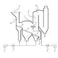
都市ごみ等の廃棄物を焼却処理する焼却炉として、火格子式廃棄物焼却炉が広く用いられており、その代表的なものの概要構成を添付図面の図2に示す。この図2の形式の焼却炉は特許文献1にも開示されている。
A grate-type waste incinerator is widely used as an incinerator for incinerating waste such as municipal waste, and a schematic configuration of a typical one is shown in FIG. 2 of the accompanying drawings. This type of incinerator of FIG. 2 is also disclosed in
図2に示される焼却炉は、廃棄物を燃焼する主燃焼室1の下部に廃棄物の移動方向に配置され三段から成る火格子(乾燥火格子1a、燃焼火格子1bそして後燃焼火格子1c)を有し、後燃焼火格子1cの上方に位置する主燃焼室1の出口に二次燃焼室2が連設されている。上記主燃焼室1には乾燥火格子1aの上方に位置して廃棄物投入口3がそして後燃焼火格子1cの右下方には灰落下口4がそれぞれ設けられている。通常、上記二次燃焼室2は廃熱回収用の廃熱ボイラ10の一部でもあり入口近傍部分である。また、上記主燃焼室1には、燃焼火格子1bと後燃焼火格子1cにまたがる範囲で火格子の上方位置に外部からの二次空気を主燃焼室1内へ吹き込む二次空気吹込み口5が設けられている。
The incinerator shown in FIG. 2 is a three-stage grate (
図2に示される焼却炉にあっては、廃棄物投入口3から炉内に投入された廃棄物は、シュート3aを通して乾燥火格子1a上に堆積され、乾燥火格子1aの下からの空気と炉内の輻射熱により乾燥されると共に、昇温されて着火する。すなわち、上記乾燥火格子1aの直上方では、廃棄物の流れ方向の上流側たる左域空間で乾燥領域をそして下流側たる右域空間では燃焼開始領域を形成する。燃焼開始領域で着火して燃焼を開始した廃棄物は、燃焼火格子1b上に送られ、廃棄物が熱分解ガス化され可燃性ガスが発生し、燃焼火格子1bの下から送られる燃焼用の一次空気によりガス分と固形分が燃焼し、上記燃焼火格子1bの直上方空間で主燃焼領域を形成する。そして、更に後燃焼火格子1c上で、後燃焼火格子1cの下から送られる燃焼用の一次空気により固定炭素など未燃分が完全に燃焼し、該後燃焼火格子1c直上方空間で後燃焼領域を形成する。しかる後、燃焼後に残った灰は、灰落下口4より外部に排出される。かくして廃棄物は三段の火格子1a〜1cの下から吹き上げる一次空気により、燃焼する。
In the incinerator shown in FIG. 2, the waste introduced into the furnace through the waste inlet 3 is deposited on the
このような焼却炉では、廃棄物の燃焼は主燃焼室1内で行われ、燃焼排ガスに含まれている未燃ガスは、二次空気吹込み口5からの二次空気を受けて二次燃焼室2で二次的な燃焼が行われて未燃分が完全に燃焼する。二次燃焼室2からの排ガスは、廃熱ボイラ10にて熱交換された後に、減温塔、バグフィルタ(共に図示せず)等を経由して無害化された状態で煙突から外部に放出される。廃熱ボイラでは、高温の燃焼排ガスから熱交換器により熱回収され蒸気を発生し、その蒸気を熱供給,発電等に供している。
In such an incinerator, the combustion of waste is performed in the
この図2の焼却炉は、一次空気と二次空気の2系統の燃焼用空気供給系を備え、一次空気供給系はファン6からダンパ等の流量調節機構7を介して火格子1a〜1cに空気を送り込む系統であり、二次空気供給系はファン8からダンパ等の流量調節機構9を介して二次空気を吹込み口5から主燃焼室1内に吹き込む系統である。
The incinerator of FIG. 2 includes two systems of combustion air supply systems, primary air and secondary air. The primary air supply system is connected from the fan 6 to the
図2に示されるような従来の廃棄物焼却炉では、実際に炉内に供給する空気量を廃棄物の燃焼に必要な理論空気量で除した比は(空気比)は、通常1.6程度である。これは、一般燃料の燃焼に必要な空気比である1.05〜1.2に比べて大きくなっている。その理由は、廃棄物には、上記一般燃料としての液体燃料や気体燃料に比べて不燃分が多く、かつ燃料分の分布が不均質なため、空気の利用効率が低く、燃焼を行うには多量の空気が必要となるためである。しかし、単に供給空気を多くすると、空気比が大きくなるにしたがって排ガス量も多くなるので、これに伴ってより大きな排ガス処理設備が必要となる。 In the conventional waste incinerator as shown in FIG. 2, the ratio (air ratio) obtained by dividing the amount of air actually supplied into the furnace by the theoretical amount of air necessary for combustion of waste is usually 1.6. Degree. This is larger than 1.05 to 1.2 which is an air ratio necessary for combustion of general fuel. The reason for this is that waste has a higher incombustibility than liquid fuel and gaseous fuel as general fuel, and the distribution of fuel is inhomogeneous. This is because a large amount of air is required. However, if the supply air is simply increased, the amount of exhaust gas increases as the air ratio increases, and accordingly, a larger exhaust gas treatment facility is required.
焼却炉において空気比を小さくした状態で支障なく廃棄物を燃焼することができれば排ガス量は低減し、排ガス処理設備がコンパクトになり、その結果、廃棄物焼却施設全体が小型化して設備費を低減できる。これに加えて、排ガス処理のための薬剤量も低減するので、運転費を低減できる。さらには、熱回収できずに大気に捨てられる熱量を低減させ、廃熱ボイラの熱回収率を向上できるので、廃棄物発電の効率を上げることができる。 If waste can be burned without problems in an incinerator with a reduced air ratio, the amount of exhaust gas will be reduced, and the exhaust gas treatment facility will become compact. As a result, the entire waste incineration facility will be downsized and equipment costs will be reduced. it can. In addition, since the amount of chemicals for exhaust gas treatment is also reduced, the operating cost can be reduced. Furthermore, since the amount of heat that cannot be recovered and discarded to the atmosphere can be reduced and the heat recovery rate of the waste heat boiler can be improved, the efficiency of waste power generation can be increased.
このような状況のもとで、空気比を1.3以下の低空気比で廃棄物焼却炉を操業することが検討されている。低空気比操業を行うことにより焼却炉より排出される排ガス量が低減されるため、排ガスの体積当たりの顕熱が増加し廃熱ボイラでの熱回収効率が向上して発生蒸気による発電効率が向上でき、また、排ガス処理設備をコンパクトにでき廃棄物焼却設備全体をコンパクトにできる効果がある。 Under such circumstances, it has been studied to operate a waste incinerator with a low air ratio of 1.3 or less. Since the amount of exhaust gas discharged from the incinerator is reduced by operating at a low air ratio, the sensible heat per volume of the exhaust gas increases, the heat recovery efficiency in the waste heat boiler is improved, and the power generation efficiency by the generated steam is increased. The exhaust gas treatment facility can be made compact, and the entire waste incineration facility can be made compact.
しかしながら、このように、低空気比燃焼に対する利点は大きくなるが、一方で、低空気比燃焼では燃焼が不安定になるという問題が残る。すなわち、低空気比で廃棄物を燃焼させると、燃焼が不安定となり、COの発生が増加したり、火炎温度が局所的に上昇してNOxが急増したり、煤が大量に発生したり、クリンカが発生したり、局所的な高温により炉の耐火物の寿命が短くなるという問題点がある。 As described above, however, the advantage over the low air ratio combustion becomes large, but the problem remains that the combustion becomes unstable in the low air ratio combustion. That is, if waste is burned at a low air ratio, the combustion becomes unstable, the generation of CO increases, the flame temperature rises locally, NOx increases rapidly, soot is generated in large quantities, There are problems that clinker is generated and that the lifetime of the refractory in the furnace is shortened due to local high temperatures.
火格子式焼却炉では、焼却炉へ供給する空気量を低減して低空気比燃焼を指向する場合でも、乾燥、燃焼、後燃焼のため火格子から供給する一次空気は空気比1.2程度は供給しないと廃棄物の燃焼状況が悪化してしまい、燃え切りが悪くなり灰分中未燃分の増加(熱勺減量の増加)につながることになってしまう。したがって、低空気比燃焼での操業を行うためには、二次空気量をも減少させることが試みられているが、次のような問題がある。すなわち、二次空気は火格子上の廃棄物層の上方で焼却炉側壁に設けた複数のノズルから炉幅方向(水平方向)に吹き込むようになっている。その結果、低空気比燃焼の操業を指向し二次空気量を減少させると、ノズルから供給された二次空気は炉中央部まで到達できず、炉中央部では二次空気が炉内発生ガスと十分な混合がなされないまま、炉壁側に沿って上昇してしまうため、未燃ガスが完全燃焼されず、燃焼排ガス中に数百ppmオーダのCOガスが残存する場合があり、COスパイクの発生の原因ともなる。COスパイクが発生すると、有害物質を含んだ排ガスが炉外に放出されることになり、公害防止の上から好ましくない。そのため低空気比燃焼を実現するのが困難になっている。 In the grate-type incinerator, even if the amount of air supplied to the incinerator is reduced and the low air ratio combustion is aimed at, the primary air supplied from the grate for drying, combustion, and post-combustion is about 1.2 air ratio If it is not supplied, the state of combustion of the waste will deteriorate, burning out will worsen, leading to an increase in unburned ash (increased heat loss). Therefore, in order to operate at low air ratio combustion, attempts have been made to reduce the amount of secondary air, but there are the following problems. That is, secondary air is blown in the furnace width direction (horizontal direction) from a plurality of nozzles provided on the incinerator side wall above the waste layer on the grate. As a result, when the amount of secondary air is reduced with a low air ratio combustion operation, the secondary air supplied from the nozzle cannot reach the center of the furnace, and the secondary air is generated in the furnace at the center of the furnace. In this case, the unburned gas may not be completely burned and CO gas on the order of several hundred ppm may remain in the combustion exhaust gas. It also causes the occurrence of. When the CO spike is generated, exhaust gas containing harmful substances is discharged outside the furnace, which is not preferable for preventing pollution. Therefore, it is difficult to realize low air ratio combustion.
本発明は、かかる事情に鑑み、低空気比燃焼を行った場合においても、CO等の有害ガスの発生を抑制でき、廃棄物を安定して燃焼できる火格子式の廃棄物焼却炉及び廃棄物焼却方法を提供することを課題とする。 In view of such circumstances, the present invention is a grate-type waste incinerator and waste that can suppress the generation of harmful gases such as CO even when low air ratio combustion is performed and can stably burn waste. It is an object to provide an incineration method.
本発明によると、上記課題は、次のように構成される廃棄物焼却炉あるいは廃棄物焼却方法によって解決される。 According to the present invention, the above problem is solved by a waste incinerator or a waste incineration method configured as follows.
<廃棄物焼却炉>
本発明に係る廃棄物焼却炉は、廃棄物投入口から投入された廃棄物を燃焼する主燃焼室を有し、主燃焼室での燃焼後の未燃ガスを燃焼する二次燃焼室が該主燃焼室の出口側に接続されており、主燃焼室下部に、乾燥火格子、燃焼火格子そして後燃焼火格子が順に設けられていると共に、乾燥火格子と燃焼火格子のそれぞれの下方から一次空気を供給する一次空気供給手段が設けられている。
<Waste incinerator>
A waste incinerator according to the present invention has a main combustion chamber for burning waste input from a waste input port, and a secondary combustion chamber for burning unburned gas after combustion in the main combustion chamber It is connected to the outlet side of the main combustion chamber. A dry grate, a combustion grate, and a post-combustion grate are provided in this order at the bottom of the main combustion chamber. Primary air supply means for supplying primary air is provided.
かかる廃棄物焼却炉において、本発明では、後燃焼火格子の下方から100〜200℃の高温空気を供給する高温空気供給手段が設けられており、高温空気が主燃焼室を経て二次燃焼室へ供給されるようになっていることを特徴としている。 In such a waste incinerator, in the present invention, high temperature air supply means for supplying high temperature air of 100 to 200 ° C. from below the post combustion grate is provided, and the high temperature air passes through the main combustion chamber and the secondary combustion chamber. It is characterized by being supplied to.
本発明において、高温空気供給手段は、後燃焼火格子上の廃棄物の未燃分を燃焼すること、そして二次燃焼室で未燃ガスを燃焼することに十分な高温空気量を供給する供給能力を有していることが好ましい。 In the present invention, the high-temperature air supply means supplies the amount of high-temperature air sufficient to burn the unburned portion of the waste on the post-combustion grate and to burn the unburned gas in the secondary combustion chamber. It is preferable to have the capability.
<廃棄物焼却方法>
本発明に係る廃棄物焼却方法は、廃棄物投入口から投入された廃棄物を燃焼する主燃焼室を有し、主燃焼室での燃焼後の未燃ガスを燃焼する二次燃焼室が該主燃焼室の出口側に接続されており、主燃焼室下部に、乾燥火格子、燃焼火格子そして後燃焼火格子が順に設けられている廃棄物焼却炉にて、乾燥火格子と燃焼火格子のそれぞれの下方から一次空気を供給する。
<Waste incineration method>
The waste incineration method according to the present invention has a main combustion chamber for burning waste input from a waste inlet, and the secondary combustion chamber for burning unburned gas after combustion in the main combustion chamber includes the main combustion chamber. In a waste incinerator that is connected to the outlet side of the main combustion chamber and is provided with a dry grate, a combustion grate, and a post-combustion grate in the lower part of the main combustion chamber, Primary air is supplied from below each of the above.
かかる廃棄物焼却方法において、本発明では、後燃焼火格子の下方から100〜200℃の高温空気を供給し、高温空気が主燃焼室を経て二次燃焼室へ供給されることを特徴としている。 In such a waste incineration method, the present invention is characterized in that high-temperature air of 100 to 200 ° C. is supplied from below the post-combustion grate, and the high-temperature air is supplied to the secondary combustion chamber through the main combustion chamber. .
本発明において、高温空気は、後燃焼火格子上の廃棄物の未燃分を燃焼すること、そして二次燃焼室で未燃ガスを燃焼することに十分な高温空気量を供給されることが好ましい。 In the present invention, the high-temperature air may be supplied with a sufficient amount of high-temperature air to burn unburned waste on the post-combustion grate and to burn unburned gas in the secondary combustion chamber. preferable.
このような本発明の廃棄物焼却炉そして廃棄物焼却方法にあっては、乾燥火格子そして燃焼火格子のそれぞれの下方から一次空気が供給されることに加えて、100〜200℃の高温空気が後燃焼火格子の下方から供給されるので、後燃焼火格子上での燃焼反応性が格段に向上する。そのため、高温空気により、後燃焼火格子の廃棄物の未燃分が効率よく燃焼されるとともに、高温空気が主燃焼室を経て二次燃焼室へ供給され、二次燃焼室で未燃ガスを完全に燃焼することができる。そのため、低空気比燃焼でも廃棄物、未燃ガスを安定して燃焼することができ、COなど有害物の発生を抑制でき、低空気比燃焼を達成できる。 In such a waste incinerator and waste incineration method of the present invention, in addition to supplying primary air from below the dry grate and the combustion grate, high-temperature air at 100 to 200 ° C. Is supplied from below the post-combustion grate, the combustion reactivity on the post-combustion grate is significantly improved. Therefore, the high-temperature air efficiently burns the unburned waste of the post-combustion grate, and the high-temperature air is supplied to the secondary combustion chamber through the main combustion chamber, and unburned gas is removed in the secondary combustion chamber. Can burn completely. Therefore, even in low air ratio combustion, waste and unburned gas can be stably burned, generation of harmful substances such as CO can be suppressed, and low air ratio combustion can be achieved.
この高温空気は、後燃焼火格子の炉幅方向全体に形成されている該後燃焼火格子の通気孔を通過し、炉幅方向(水平方向)に均等に分散された後に、後燃焼火格子の上方の主燃焼室を経て上昇した後、二次燃焼室へ至る。その結果、低空気比燃焼のもとでも、二次燃焼室には炉幅方向中央部でも十分に均一に高温空気が行きわたり、未燃ガスの燃焼が良好に行われる。 This high-temperature air passes through the vent holes of the post-combustion grate formed in the entire furnace width direction of the post-combustion grate and is uniformly distributed in the furnace width direction (horizontal direction), and then the post-combustion grate After rising through the main combustion chamber above, the secondary combustion chamber is reached. As a result, even under the low air ratio combustion, the high-temperature air reaches the secondary combustion chamber sufficiently uniformly even in the center portion in the furnace width direction, and the unburned gas is burned well.
また、高温空気により、後燃焼火格子の廃棄物の未燃分が効率よく燃焼されるため、常温空気を供給する場合に比べて、後燃焼火格子上での未燃分の後燃焼に必要な時間を短くすることができ、後燃焼火格子の面積を縮小することができる。 In addition, the high-temperature air efficiently burns the unburned waste of the post-burning grate, so it is necessary for the post-burning of the unburned content on the post-burning grate compared to supplying normal temperature air. Time can be shortened, and the area of the post-combustion grate can be reduced.
また、二次燃焼室における未燃ガスの二次燃焼のための二次空気を、後燃焼火格子下から供給する高温空気だけで賄うこともできるため、従来、後燃焼火格子の上方空間へ直接供給されていた二次燃焼用空気の供給のための機構を別途設けることを省くこともできる。 In addition, since secondary air for secondary combustion of unburned gas in the secondary combustion chamber can be covered only with high-temperature air supplied from below the post-combustion grate, conventionally, the space above the post-combustion grate A separate mechanism for supplying the secondary combustion air that has been directly supplied can be omitted.
本発明は、以上のように、後燃焼火格子の下方から100〜200℃の高温空気を供給することとしたので、後燃焼火格子の廃棄物の未燃分が効率よく燃焼されるとともに、高温空気が主燃焼室を経て二次燃焼室へ供給され、二次燃焼室において、未燃ガスを完全に燃焼することができる。そのため、低空気比燃焼でも廃棄物、未燃ガスを安定して燃焼することができ、COなど有害物の発生を抑制でき、低空気比燃焼を達成できる廃棄物焼却炉及び廃棄物焼却方法を提供することができる。 As described above, since the present invention supplies high-temperature air of 100 to 200 ° C. from below the post-combustion grate, the unburned matter of the waste of the post-combustion grate is efficiently burned, Hot air is supplied to the secondary combustion chamber through the main combustion chamber, and the unburned gas can be completely burned in the secondary combustion chamber. Therefore, a waste incinerator and a waste incineration method that can stably burn waste and unburned gas even with low air ratio combustion, can suppress the generation of harmful substances such as CO, and can achieve low air ratio combustion. Can be provided.
以下、添付図面の図1にもとづき、本発明の実施の形態を説明する。 Hereinafter, an embodiment of the present invention will be described with reference to FIG. 1 of the accompanying drawings.
<第一実施形態>
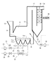
図1に示される本実施形態の廃棄物焼却炉は、廃棄物を燃焼するための主燃焼室11の出口側に二次燃焼室12が連設されている。二次燃焼室12は廃熱回収のための廃熱ボイラ17の一部でもあり入口近傍部分である。
<First embodiment>
In the waste incinerator of this embodiment shown in FIG. 1, a
主燃焼室11の下部には、廃棄物の移動方向(図では右方向)で、上流側から乾燥火格子11a、燃焼火格子11b、そして後燃焼火格子11cが順に設けられている。各火格子11a,11b,11cはそれぞれ、火格子上の廃棄物を右方に移動させる動作を伴っている。
In the lower part of the
上記焼却炉では、乾燥火格子11aの上流側の上方に、廃棄物投入口13が設けられており、該廃棄物投入口13から垂下するシュート14により上記主燃焼室11の上部空間に連通していて、廃棄物投入口13から投入された廃棄物が上記シュート14を経て、図示しない廃棄物供給機構により上記乾燥火格子11aに供給されるようになっている。該乾燥火格子11a上に供給された廃棄物は、各火格子11a〜11cの動作によって、火格子上に廃棄物の層を形成しつつ燃焼火格子11bそして後燃焼火格子11cへと移動する。各火格子11a〜11cの下方には、燃焼用の空気の供給を受けるための風箱11a−1,11b−1,11c−1が設けられている。燃焼用の一次空気は、火格子上の廃棄物の乾燥及び燃焼に使われるほか、火格子の冷却作用、廃棄物の攪拌作用を有する。また、後燃焼火格子11cに対して下流側で隣接する位置に、下方に開口する灰落下口15が設けられている。
In the incinerator, a
主燃焼室11の出口部(下流側)の上方位置で該主燃焼室11に二次燃焼室12が連設されている。廃熱ボイラ17はその入口近傍部分が二次燃焼室12であり、二次燃焼室12に続いて屈曲流路空間が形成され、内壁面の水冷壁や伝熱管群により廃熱を回収し、上方の排出口17aから排ガスを次工程処理のために排出するようになっている。
A
本実施形態では、焼却炉は、燃焼用空気となる一次空気、高温空気そして、好ましい形態として、さらに二次空気の3系統の空気供給系を備えている。一次空気供給系21は、空気供給源からの空気を管路22を経て、乾燥火格子11a、燃焼火格子11bのそれぞれの風箱11a−1,11b−1に分岐供給管21a,21bから送り込むようになっており、上記管路22には、圧送用ファン23そして流量調整機構としてのダンパ24が設けられている。高温空気供給系25は、上記空気供給源からの空気を、管路26に設けられた空気予熱器27で予熱した後に、後燃焼火格子11cの風箱11c−1に送り込むようになっており、上記管路26には、圧送用ファン28そして流量調整機構としてのダンパ29が設けられている。また、二次空気供給系31は、空気供給源からの空気を管路32を経て、二次燃焼室12に送り込むようになっており、上記管路32には、圧送用ファン33そして供給量調整機構としてのダンパ34が設けられている。なお、上記風箱及び燃焼用の一次空気、高温空気そして二次空気を供給するための管路等の構成は図示したものに限定されず、焼却炉の規模、形状、用途等により適宜選択され得る。廃熱ボイラ17の排出口17aには、排出口17aから排出される排ガスの酸素濃度を検出する酸素濃度計35が設けられていて、炉外に設けられた制御装置36に該酸素濃度計35の検出信号が送られ、制御装置36が検出酸素濃度に応じて上記ダンパ34の開度を制御するようになっている。
In the present embodiment, the incinerator is provided with three air supply systems of primary air that is combustion air, high-temperature air, and, as a preferable mode, secondary air. The primary
上記一次空気供給系21、高温空気供給系25そして二次空気供給系31の空気供給源は、互いに共通でも個別に設けられていてもよい。
The air supply sources of the primary
後燃焼火格子11cの下から供給する高温空気の温度は、100〜200℃の範囲とされている。その理由は、吹き込む高温空気の温度を100℃未満とすると、二次燃焼室の温度が低下し、未燃ガスの二次燃焼が不安定となり、COが増加してしまうし、高温空気の温度が200℃を超えると高温化に見合った経済的効果がないからである。また、上記空気予熱器27の熱源としては廃熱ボイラで生成された蒸気を用いることができる。
The temperature of the high-temperature air supplied from under the
本実施形態では、後燃焼火格子11cの下から高温空気を吹き込むので、後燃焼火格子11c上の廃棄物の未燃分は、高温空気によって加熱され、燃焼が促進され、完全に燃焼が終了する。高温空気により、後燃焼火格子11c上の廃棄物の未燃分が効率よく燃焼されるため、常温空気を供給する場合に比べて、後燃焼火格子11c上での未燃分の後燃焼に必要な時間を短くすることができ、後燃焼火格子11cの長さを縮小することができる。
In the present embodiment, since high-temperature air is blown from the bottom of the
本実施形態では、好ましい形態として、さらに、二次空気供給系31に二次空気の供給量調整機構としてのダンパ34を有しているが、その場合には、二次燃焼室12を含む廃熱ボイラ17からの排ガスの酸素濃度を上記酸素濃度計35で検出して、その濃度が所定範囲内に収まるように、上記ダンパ34を制御して二次空気の供給量を増減する。二次燃焼室12における未燃ガスの二次燃焼のための二次空気を、後燃焼火格子11c下から供給する高温空気だけで十分に賄うこともできる場合には、二次空気供給系31を省略することもできる。
In this embodiment, as a preferred embodiment, the secondary
このような本実施形態の焼却炉では、各火格子11a〜11cの上に廃棄物の層が形成される。
In such an incinerator of this embodiment, a waste layer is formed on each
乾燥火格子11aの直上方で該乾燥火格子11a上であって廃棄物の流れ方向の上流側範囲には乾燥領域が形成され、下流側範囲には燃焼開始領域が形成される。すなわち、乾燥火格子11aの廃棄物は、上流側範囲で乾燥され、下流側範囲で着火して燃焼が開始し燃焼火格子11bへと移動する。燃焼火格子11b上の廃棄物はここで熱分解そして部分酸化が行われ、可燃ガスと固形分が燃焼する。廃棄物はこの燃焼火格子11b上で実質的に殆んど燃焼される。こうして、上記燃焼火格子11b直上に主燃焼領域が形成される。しかる後、僅かに残った廃棄物中の固定炭素など未燃分が後燃焼火格子に移動して該後燃焼火格子11c上で完全に燃焼される。この後燃焼火格子11c上に後燃焼領域が形成される。
A dry region is formed in the upstream range in the waste flow direction on the
主燃焼室11内で発生した未燃ガスは、上記後燃焼火格子11cの上方に位置する二次燃焼室12に流入してここで燃焼し、上記後燃焼領域の上方に二次燃焼領域を形成する。
Unburned gas generated in the
このような本実施形態の焼却炉は、次の要領で運転される。 Such an incinerator of this embodiment is operated in the following manner.
先ず、廃棄物投入口13へ廃棄物を投入すると、シュート14を経て、廃棄物は乾燥火格子11aに堆積され、各火格子11a〜11cの動作により、燃焼火格子11b上そして後燃焼火格子11c上へと移動し、各火格子11a〜11c上に廃棄物の層を形成する。
First, when waste is introduced into the
各火格子11a〜11cは、風箱11a−1,11b−1を経て燃焼用の一次空気を、そして風箱11c−1を経て高温空気をそれぞれ受けており、これにより各火格子11a〜11c上の廃棄物は燃焼する。
Each
乾燥火格子11aでは主として廃棄物の乾燥と着火が行われる。すなわち、乾燥火格子11aの廃棄物の流れ方向の上流側域で乾燥がそして下流側域で着火(燃焼開始)が行われる。燃焼火格子11bでは主として廃棄物の熱分解、部分酸化が行われ、可燃性ガスと固形分の燃焼が行われる。燃焼火格子11bにおいて廃棄物の燃焼は実質的に完了する。後燃焼火格子11c上では、僅かに残った廃棄物中の固定炭素など未燃分を完全におき燃焼させる。完全に燃焼した後の燃焼灰は、灰落下口15より排出される。このように廃棄物が燃焼している状態で、各火格子11a〜11c直上空間には、上述の乾燥領域、燃焼開始領域、主燃焼領域そして後燃焼領域がそれぞれ形成される。
In the
本実施形態では、後燃焼火格子11cには、空気予熱器27で予熱された高温空気が圧送用ファン28により風箱11c−1を経て供給される。上記風箱11c−1内に送入された高温空気は、後燃焼火格子11cの炉幅方向全体に形成されている通気孔を通過し、炉幅方向(図1にて紙面に直角方向)均一に分布した状態で、主燃焼室11内の後燃焼領域を経てその上方の二次燃焼室12へ至ることとなり、ここで二次空気供給系31で供給される二次空気とともに二次燃焼に寄与する。
In the present embodiment, the hot air preheated by the
本実施形態では、高温空気を後燃焼火格子11cの下方から送入することとしたので、高温空気が炉幅方向で均一に行きわたり、その結果、低空気比燃焼においても、空気量が不十分な領域がなくなり、二次燃焼室12内の未燃ガス量に応じた最低限の空気量の供給で二次燃焼を行うことができる。
In the present embodiment, since the high-temperature air is fed from below the
上記二次空気の供給量は、制御装置36によるダンパ34の開度を増減して調整されるが、これは、酸素濃度計35により検出された廃熱ボイラ17の排出口17aの排ガスの検出酸素濃度が、所定範囲内に収まるように行われる。排ガスの酸素濃度はCO濃度と相関しており、この酸素濃度の所定範囲の下限は、COスパイクが起きないような酸素濃度として定め、上限を極力低空気比となる値として定めることにより、上記所定範囲を決定する。
The supply amount of the secondary air is adjusted by increasing / decreasing the opening degree of the
既述のごとく、廃棄物投入口13とは反対側となる主燃焼室11の出口に、廃熱ボイラ17の一部である二次燃焼室12が連設されている。したがって、主燃焼室11内で発生した未燃ガスは、二次燃焼室12に導かれ、そこで上述の高温空気と二次空気と混合・攪拌され、二次燃焼し、二次燃焼室12からの燃焼排ガスは廃熱ボイラ17で熱回収される。熱回収された後、廃熱ボイラ17から排出された燃焼排ガスは、消石灰による酸性ガスの中和と、活性炭によるダイオキシン類の吸着が行われ、さらに除塵装置(図示せず)に送られ、活性炭や中和反応物などが回収される。上記除塵装置で除塵され、無害化された後の燃焼排ガスは、誘引ファン(図示せず)により誘引され、煙突から大気中に放出される。なお、上記第一そして第二の除塵装置としては、例えば、バグフィルタ方式、電気集塵方式等の除塵装置を用いることができる。
As described above, the
次に、本実施形態において、二次燃焼室の雰囲気そして排ガス酸素濃度にもとづく二次空気量の制御について詳述する。 Next, in the present embodiment, control of the secondary air amount based on the atmosphere of the secondary combustion chamber and the exhaust gas oxygen concentration will be described in detail.
<二次燃焼室の雰囲気>
二次燃焼室内のガス温度は、800〜1050℃の範囲となるように、二次空気の流量を調整することが好ましい。その理由は、二次燃焼室内のガス温度が800℃未満となると燃焼が不十分となり、COが増加してしまうからであり、また、二次燃焼室内のガス温度が1050℃を超えると二次燃焼室内におけるクリンカの生成が助長され、さらに、NOxが増加してしまうからである。
<Atmosphere of secondary combustion chamber>
It is preferable to adjust the flow rate of the secondary air so that the gas temperature in the secondary combustion chamber is in the range of 800 to 1050 ° C. The reason is that if the gas temperature in the secondary combustion chamber becomes less than 800 ° C., combustion becomes insufficient and CO increases, and if the gas temperature in the secondary combustion chamber exceeds 1050 ° C., the secondary combustion chamber becomes secondary. This is because generation of clinker in the combustion chamber is promoted, and NOx is further increased.
<排ガス酸素濃度にもとづく二次空気量の制御>
本実施形態において、廃熱ボイラ17の排出口17aの排ガスの酸素濃度を測定し、これにもとづいて二次空気供給量を制御することとしているが、この酸素濃度と排ガス中のCO濃度、排ガス中のNOx濃度、二次空気供給量との関係を表1に示す。
<Control of secondary air volume based on exhaust gas oxygen concentration>
In the present embodiment, the oxygen concentration of the exhaust gas at the
焼却炉内で廃棄物と熱分解によって発生する可燃性ガスを適正な酸素濃度や温度等の範囲内で燃焼させた場合に、CO、NOx、DXN(ダイオキシン類)等の有害物質の発生が最も抑制される。表1において、ボイラ出口近傍での排ガス中酸素濃度が高い場合は、焼却炉から排出されるCO濃度は減少するかあるいは変化無しであるが、NOx濃度は増加する。そのため、二次空気供給量を減少させ、二次燃焼室への酸素の供給量を減少させて二次燃焼室の燃焼を適正に行うようにする。反対に、ボイラ出口近傍での排ガス中酸素濃度が低い場合は、焼却炉から排出されるNOx濃度は減少するかあるいは変化無しの状態となるが、CO濃度は増加する状態となる。そのため、二次空気供給量を増加させ、二次燃焼室への酸素の供給量を増やし、二次燃焼室の燃焼を適正に行うようにする。 When combustible gas generated by waste and thermal decomposition in an incinerator is combusted within the range of appropriate oxygen concentration and temperature, the most harmful substances such as CO, NOx, DXN (dioxins) are generated. It is suppressed. In Table 1, when the oxygen concentration in the exhaust gas near the boiler outlet is high, the CO concentration discharged from the incinerator decreases or remains unchanged, but the NOx concentration increases. Therefore, the secondary air supply amount is decreased and the oxygen supply amount to the secondary combustion chamber is decreased so that the combustion in the secondary combustion chamber is appropriately performed. On the contrary, when the oxygen concentration in the exhaust gas near the boiler outlet is low, the NOx concentration discharged from the incinerator decreases or remains unchanged, but the CO concentration increases. Therefore, the secondary air supply amount is increased, the oxygen supply amount to the secondary combustion chamber is increased, and combustion in the secondary combustion chamber is appropriately performed.

以上説明したように本発明によれば、廃棄物焼却炉において低空気比燃焼を行った場合においても燃焼の安定性が維持され、且つ、局所高温領域の発生が抑制され、COやNOx等の有害ガスの発生量が低減できる廃棄物焼却炉及び廃棄物焼却方法が提供される。さらに、低空気比燃焼を行えるので焼却炉から排出される排ガス総量を大幅に低減でき、また、廃熱の回収効率を向上できる廃棄物焼却炉及び廃棄物焼却方法が提供される。 As described above, according to the present invention, even when low air ratio combustion is performed in a waste incinerator, the stability of combustion is maintained, the occurrence of local high temperature regions is suppressed, and CO, NOx, etc. Provided are a waste incinerator and a waste incineration method capable of reducing the generation amount of harmful gas. Furthermore, since a low air ratio combustion can be performed, the total amount of exhaust gas discharged from the incinerator can be significantly reduced, and a waste incinerator and a waste incineration method that can improve waste heat recovery efficiency are provided.
11 主燃焼室
11a 乾燥火格子
11b 燃焼火格子
11c 後燃焼火格子
12 二次燃焼室
13 廃棄物投入口
21 一次空気供給手段
DESCRIPTION OF
Claims (2)
二次燃焼室が後燃焼火格子の上方に設けられた主燃焼室の出口に接続され、
乾燥火格子と燃焼火格子のそれぞれの下方から予熱しない一次空気を供給する一次空気供給手段と、後燃焼火格子の下方から100〜200℃の高温空気を供給する高温空気供給手段と、二次燃焼室へ二次空気を供給する二次空気供給手段と、二次空気供給量を制御する制御装置と、廃熱ボイラから排出される排ガスの酸素濃度を測定する酸素濃度計とを有し、
一次空気供給手段と高温空気供給手段と二次空気供給手段とが、一次空気、高温空気及び二次空気により供給する総空気量を廃棄物の燃焼に必要な理論空気量で除した空気比を1.3以下の低空気比とするように一次空気、高温空気及び二次空気を供給し、
高温空気供給手段は、高温空気を後燃焼火格子の下方から供給し上方へ上昇させ主燃焼室から二次燃焼室内に流入させ、後燃焼火格子上の廃棄物の未燃分を燃焼すること、そして二次燃焼室で二次空気とともに未燃ガスと混合して未燃ガスを燃焼することのための必要量以上の高温空気量を供給し、
制御装置は、酸素濃度計により測定された排ガス中酸素濃度測定値に基づき、排ガス中酸素濃度測定値が所定範囲より高いとき二次空気供給量を減少し、所定範囲より低いとき二次空気供給量を増加することで、測定値が所定範囲内に収まるように二次空気供給量を制御する、
ことを特徴とする廃棄物焼却炉。 A main combustion chamber in which a dry grate, a combustion grate, and a post-combustion grate are sequentially provided to burn waste, a secondary combustion chamber to burn unburned gas after combustion in the main combustion chamber, and a waste heat boiler. In the grate-type waste incinerator with
A secondary combustion chamber is connected to the outlet of the main combustion chamber provided above the post-combustion grate,
Primary air supply means for supplying primary air that is not preheated from below each of the dry grate and the combustion grate, high temperature air supply means for supplying high-temperature air of 100 to 200 ° C. from below the post-combustion grate, and secondary A secondary air supply means for supplying secondary air to the combustion chamber, a control device for controlling the secondary air supply amount, and an oxygen concentration meter for measuring the oxygen concentration of the exhaust gas discharged from the waste heat boiler,
The primary air supply means, the high-temperature air supply means, and the secondary air supply means have an air ratio obtained by dividing the total amount of air supplied by the primary air, the high-temperature air, and the secondary air by the theoretical amount of air necessary for waste combustion. Supply primary air, high temperature air and secondary air so as to have a low air ratio of 1.3 or less,
Hot air supply means to flow from the supply to the main combustion chamber is raised upward from the lower side of the post-combustion grate hot air into the secondary combustion chamber, burning unburned waste on post-combustion grate And, in the secondary combustion chamber, supply an amount of high-temperature air that is greater than the amount required to burn the unburned gas by mixing with the unburned gas together with the secondary air
The control device reduces the secondary air supply amount when the measured oxygen concentration in the exhaust gas is higher than a predetermined range based on the measured value of the oxygen concentration in the exhaust gas measured by the oximeter, and supplies the secondary air when it is lower than the predetermined range. By increasing the amount, the secondary air supply amount is controlled so that the measured value falls within the predetermined range.
Waste incinerator characterized by that.
乾燥火格子と燃焼火格子のそれぞれの下方から予熱しない一次空気を供給し、高温空気供給手段により後燃焼火格子の下方から100〜200℃の高温空気を供給し、二次空気供給手段により二次燃焼室の入口へ二次空気を供給し、一次空気、高温空気及び二次空気により供給する総空気量を廃棄物の燃焼に必要な理論空気量で除した空気比を1.3以下の低空気比とするように一次空気、高温空気及び二次空気を供給し、
高温空気供給手段により、高温空気を後燃焼火格子の下方から供給し上方へ上昇させ、後燃焼火格子の上方に設けられた主燃焼室出口に接続された二次燃焼室内に流入させ、後燃焼火格子上の廃棄物の未燃分を燃焼すること、そして主燃焼室から二次燃焼室内に流入し二次空気とともに未燃ガスと混合して未燃ガスを燃焼することのための必要量以上の高温空気量を供給し、
廃熱ボイラから排出される排ガスの酸素濃度を酸素濃度計により測定し、
酸素濃度計により測定された排ガス中酸素濃度測定値に基づき、排ガス中酸素濃度測定値が所定範囲より高いとき二次空気供給量を減少し、所定範囲より低いとき二次空気供給量を増加することで、測定値が所定範囲内に収まるように二次空気供給量を制御する、
ことを特徴とする廃棄物焼却方法。 A main combustion chamber in which a dry grate, a combustion grate, and a post-combustion grate are sequentially provided to burn waste, a secondary combustion chamber to burn unburned gas after combustion in the main combustion chamber, and a waste heat boiler. In a waste incineration method using a grate-type waste incinerator having
Primary air that is not preheated is supplied from below each of the dry grate and the combustion grate, high-temperature air of 100 to 200 ° C. is supplied from below the post-combustion grate by the high-temperature air supply means , and secondary air is supplied by the secondary air supply means. Secondary air is supplied to the inlet of the secondary combustion chamber, and the air ratio obtained by dividing the total amount of air supplied by the primary air, high temperature air and secondary air by the theoretical air amount necessary for combustion of waste is 1.3 or less. Supply primary air, high temperature air and secondary air so as to have a low air ratio,
Hot air is supplied from below the post-combustion grate by the high- temperature air supply means, is raised upward, and flows into the secondary combustion chamber connected to the main combustion chamber outlet provided above the post-combustion grate. burning unburned waste on the combustion grate, and the main combustion chamber from the secondary with inflowing secondary air into the combustion chamber for burning the unburnt gas is mixed with unburned gas Supply more hot air than necessary ,
Measure the oxygen concentration of the exhaust gas discharged from the waste heat boiler with an oxygen concentration meter,
Based on the measured oxygen concentration value in the exhaust gas measured by the oximeter, when the measured oxygen concentration value in the exhaust gas is higher than the predetermined range, the secondary air supply amount is decreased, and when it is lower than the predetermined range, the secondary air supply amount is increased. By controlling the secondary air supply amount so that the measured value falls within the predetermined range,
Waste incineration method characterized by that.
Priority Applications (1)
| Application Number | Priority Date | Filing Date | Title |
|---|---|---|---|
| JP2012132784A JP5800237B2 (en) | 2012-06-12 | 2012-06-12 | Waste incinerator and waste incineration method |
Applications Claiming Priority (1)
| Application Number | Priority Date | Filing Date | Title |
|---|---|---|---|
| JP2012132784A JP5800237B2 (en) | 2012-06-12 | 2012-06-12 | Waste incinerator and waste incineration method |
Publications (2)
| Publication Number | Publication Date |
|---|---|
| JP2013257065A JP2013257065A (en) | 2013-12-26 |
| JP5800237B2 true JP5800237B2 (en) | 2015-10-28 |
Family
ID=49953651
Family Applications (1)
| Application Number | Title | Priority Date | Filing Date |
|---|---|---|---|
| JP2012132784A Active JP5800237B2 (en) | 2012-06-12 | 2012-06-12 | Waste incinerator and waste incineration method |
Country Status (1)
| Country | Link |
|---|---|
| JP (1) | JP5800237B2 (en) |
Families Citing this family (4)
| Publication number | Priority date | Publication date | Assignee | Title |
|---|---|---|---|---|
| JP2016191539A (en) * | 2015-03-31 | 2016-11-10 | Jfeエンジニアリング株式会社 | Stoker type waste incinerator and waste incineration method |
| KR101974150B1 (en) * | 2018-04-27 | 2019-04-30 | (주)이에스 | Solid fuel combustion equipment |
| KR102196355B1 (en) * | 2018-07-31 | 2020-12-30 | (주)이에스 | Solid fuel incinerator |
| CN109737445A (en) * | 2019-01-06 | 2019-05-10 | 大唐(北京)能源管理有限公司 | A kind of boiler exhaust smoke waste-heat utilization system of external First air heater |
Family Cites Families (5)
| Publication number | Priority date | Publication date | Assignee | Title |
|---|---|---|---|---|
| JP2002228129A (en) * | 2001-01-29 | 2002-08-14 | Mitsubishi Heavy Ind Ltd | Waste incinerator |
| JP2003166706A (en) * | 2001-11-29 | 2003-06-13 | Mitsubishi Heavy Ind Ltd | Combustion method and combustion device of stoker type incinerator |
| JP2004077014A (en) * | 2002-08-15 | 2004-03-11 | Jfe Engineering Kk | Operation method of waste incinerator |
| JP2004085094A (en) * | 2002-08-27 | 2004-03-18 | Jfe Engineering Kk | Incinerator |
| JP2004085093A (en) * | 2002-08-27 | 2004-03-18 | Jfe Engineering Kk | Combustion air temperature control method for incinerator |
-
2012
- 2012-06-12 JP JP2012132784A patent/JP5800237B2/en active Active
Also Published As
| Publication number | Publication date |
|---|---|
| JP2013257065A (en) | 2013-12-26 |
Similar Documents
| Publication | Publication Date | Title |
|---|---|---|
| JP6011295B2 (en) | Waste incinerator and waste incineration method | |
| JP2016191539A (en) | Stoker type waste incinerator and waste incineration method | |
| JP5818093B2 (en) | Waste incinerator and waste incineration method | |
| JP2017223395A (en) | Waste incineration equipment and waste incineration method | |
| JP2004084981A (en) | Waste incinerator | |
| JP5800237B2 (en) | Waste incinerator and waste incineration method | |
| JP6146673B2 (en) | Waste incinerator and waste incineration method | |
| JP5861880B2 (en) | Waste incinerator and waste incineration method | |
| WO2013133290A1 (en) | Grate-type waste incinerator and method for incinerating waste | |
| JP2013164226A (en) | Waste material incinerator and waste material incinerating method | |
| JP5871207B2 (en) | Waste incinerator and waste incineration method | |
| JP2007163078A (en) | Waste disposal method and device | |
| JP6256859B2 (en) | Waste incineration method | |
| CN107687639A (en) | Energy-saving waste combustion waste-heat recovery device | |
| JP3956862B2 (en) | Combustion control method for waste incinerator and waste incinerator | |
| JP6455717B2 (en) | Grate-type waste incinerator and waste incineration method | |
| JP6146671B2 (en) | Waste incinerator and waste incineration method | |
| JP6218117B2 (en) | Grate-type waste incinerator and waste incineration method | |
| JP2019020084A (en) | Waste incineration equipment and waste incineration method | |
| JP2015209992A (en) | Waste incineration treatment equipment and waste incineration treatment method | |
| JP2007078197A (en) | Incinerator and incinerating method of waste | |
| JP6443758B2 (en) | Grate-type waste incinerator and waste incineration method | |
| JP6090578B2 (en) | Waste incinerator and waste incineration method | |
| JP5818094B2 (en) | Waste incinerator | |
| JP6183787B2 (en) | Grate-type waste incinerator and waste incineration method |
Legal Events
| Date | Code | Title | Description |
|---|---|---|---|
| A621 | Written request for application examination |
Free format text: JAPANESE INTERMEDIATE CODE: A621 Effective date: 20140910 |
|
| A131 | Notification of reasons for refusal |
Free format text: JAPANESE INTERMEDIATE CODE: A131 Effective date: 20150406 |
|
| A977 | Report on retrieval |
Free format text: JAPANESE INTERMEDIATE CODE: A971007 Effective date: 20150408 |
|
| A521 | Written amendment |
Free format text: JAPANESE INTERMEDIATE CODE: A523 Effective date: 20150603 |
|
| TRDD | Decision of grant or rejection written | ||
| A01 | Written decision to grant a patent or to grant a registration (utility model) |
Free format text: JAPANESE INTERMEDIATE CODE: A01 Effective date: 20150731 |
|
| A61 | First payment of annual fees (during grant procedure) |
Free format text: JAPANESE INTERMEDIATE CODE: A61 Effective date: 20150813 |
|
| R150 | Certificate of patent or registration of utility model |
Ref document number: 5800237 Country of ref document: JP Free format text: JAPANESE INTERMEDIATE CODE: R150 |
|
| R157 | Certificate of patent or utility model (correction) |
Free format text: JAPANESE INTERMEDIATE CODE: R157 |
|
| S531 | Written request for registration of change of domicile |
Free format text: JAPANESE INTERMEDIATE CODE: R313531 |
|
| R350 | Written notification of registration of transfer |
Free format text: JAPANESE INTERMEDIATE CODE: R350 |