JP2015209992A - Waste incineration treatment equipment and waste incineration treatment method - Google Patents
Waste incineration treatment equipment and waste incineration treatment method Download PDFInfo
- Publication number
- JP2015209992A JP2015209992A JP2014090081A JP2014090081A JP2015209992A JP 2015209992 A JP2015209992 A JP 2015209992A JP 2014090081 A JP2014090081 A JP 2014090081A JP 2014090081 A JP2014090081 A JP 2014090081A JP 2015209992 A JP2015209992 A JP 2015209992A
- Authority
- JP
- Japan
- Prior art keywords
- waste
- exhaust gas
- combustion
- gas
- grate
- Prior art date
- Legal status (The legal status is an assumption and is not a legal conclusion. Google has not performed a legal analysis and makes no representation as to the accuracy of the status listed.)
- Pending
Links
Images


Abstract
Description
本発明は、都市ごみ等の廃棄物を焼却する火格子式の廃棄物焼却処理装置及び廃棄物焼却処理方法に関する。 The present invention relates to a grate-type waste incineration processing apparatus and a waste incineration processing method for incinerating waste such as municipal waste.
都市ごみ等の廃棄物を焼却処理する焼却炉として、火格子式廃棄物焼却炉が広く用いられている。その代表的なものの構成の概要を以下に説明する。 Grate-type waste incinerators are widely used as incinerators for incinerating waste such as municipal waste. The outline of the configuration of the representative one will be described below.
火格子式廃棄物焼却炉は、廃棄物を燃焼する燃焼室の下部に廃棄物の移動方向に配置され三段から成る火格子(乾燥火格子、燃焼火格子そして後燃焼火格子)を有し、後燃焼火格子の上方に位置する燃焼室の出口に二次燃焼室が連設されている。上記燃焼室には乾燥火格子の上方に位置して廃棄物投入口が設けられている。そして後燃焼火格子の廃棄物の移動方向下流側下方には灰落下口が設けられている。通常、上記二次燃焼室は廃熱回収用の廃熱ボイラの一部でもあり、その入口近傍部分である。また、乾燥火格子、燃焼火格子そして後燃焼火格子のそれぞれの火格子下から燃焼用一次空気を吹き込む燃焼用一次空気吹込み機構が設けられている。 The grate-type waste incinerator has a three-stage grate (dry grate, combustion grate, and post-combustion grate) that is arranged in the direction of waste movement at the bottom of the combustion chamber that burns the waste. The secondary combustion chamber is connected to the outlet of the combustion chamber located above the post-combustion grate. The combustion chamber is provided with a waste inlet located above the dry grate. An ash drop port is provided at the downstream side of the post-combustion grate waste in the moving direction. Usually, the secondary combustion chamber is also a part of a waste heat boiler for waste heat recovery, and is in the vicinity of the inlet. Further, a combustion primary air blowing mechanism for blowing combustion primary air from below the respective grate of the dry grate, the combustion grate, and the post-combustion grate is provided.
このような火格子式廃棄物焼却炉において、廃棄物投入口から燃焼室内に投入された廃棄物は、乾燥火格子上に堆積され、乾燥火格子の下からの燃焼用一次空気と炉内の輻射熱により乾燥されると共に、昇温されて着火する。すなわち、上記乾燥火格子の直上方では、廃棄物の移動方向の上流側空間で乾燥領域が形成され、乾燥火格子の直上方の下流側空間から燃焼火格子の直上方の上流側空間にかけて燃焼開始領域が形成される。燃焼開始領域で着火して燃焼を開始した廃棄物は、乾燥火格子から燃焼火格子上に送られ、廃棄物が熱分解されて可燃性ガスが発生し、燃焼火格子の下から送られる燃焼用一次空気により可燃性ガスと固形分が燃焼し、燃焼火格子の直上方空間で主燃焼領域が形成される。そして、更に後燃焼火格子上で、固定炭素など未燃分が完全に燃焼し、該後燃焼火格子の直上方空間で後燃焼領域が形成される。しかる後、燃焼後に残った灰は、灰落下口より外部に排出される。 In such a grate-type waste incinerator, the waste thrown into the combustion chamber from the waste inlet is deposited on the dry grate, the primary air for combustion from under the dry grate and the inside of the furnace While being dried by radiant heat, it is heated to ignite. That is, immediately above the dry grate, a dry region is formed in the upstream space in the waste movement direction, and combustion occurs from the downstream space directly above the dry grate to the upstream space directly above the combustion grate. A starting region is formed. The waste that ignites in the combustion start area and starts combustion is sent from the dry grate onto the combustion grate, and the waste is pyrolyzed to generate combustible gas, and the combustion sent from the bottom of the combustion grate The primary air for combustion burns combustible gas and solid content, and a main combustion region is formed in the space immediately above the combustion grate. Further, unburned components such as fixed carbon are completely burned on the post-combustion grate, and a post-combustion region is formed in a space immediately above the post-combustion grate. Thereafter, the ash remaining after combustion is discharged to the outside from the ash drop opening.
かくして、火格子式廃棄物焼却炉では、廃棄物は燃焼室にて三段の火格子の下から吹き込まれる燃焼用一次空気により燃焼する。さらに、燃焼室からの燃焼排ガスに含まれている可燃性ガスの未燃分は、二次燃焼室で二次燃焼用空気を受けて燃焼する。 Thus, in the grate-type waste incinerator, the waste is burned by the primary combustion air blown from below the three-stage grate in the combustion chamber. Further, the unburned portion of the combustible gas contained in the combustion exhaust gas from the combustion chamber receives and burns secondary combustion air in the secondary combustion chamber.
従来の火格子式廃棄物焼却炉では、実際に焼却炉内に供給する空気量を廃棄物の燃焼に必要な理論空気量で除した比(空気比)は、通常、1.6程度である。これは、一般燃料の燃焼に必要な空気比である1.05〜1.2に比べて大きくなっている。その理由は、廃棄物には、一般燃料としての液体燃料や気体燃料に比べて不燃分が多く、かつ不均質なため、空気の利用効率が低く、燃焼を行うには多量の空気が必要となるためである。しかし、単に供給空気を多くすると、空気比が大きくなるにしたがって排ガス量も多くなるので、これに伴ってより大きな排ガス処理設備が必要となる。 In a conventional grate-type waste incinerator, the ratio (air ratio) obtained by dividing the amount of air actually supplied into the incinerator by the theoretical amount of air necessary for combustion of the waste is usually about 1.6. . This is larger than 1.05 to 1.2 which is an air ratio necessary for combustion of general fuel. The reason for this is that waste has a higher incombustibility than liquid fuel or gaseous fuel as a general fuel and is inhomogeneous, so the efficiency of air utilization is low, and a large amount of air is required for combustion. Because it becomes. However, if the supply air is simply increased, the amount of exhaust gas increases as the air ratio increases, and accordingly, a larger exhaust gas treatment facility is required.
廃棄物焼却炉において空気比を小さくした状態で、支障なく廃棄物を燃焼することができれば、排ガス量は低減し、排ガス処理設備がコンパクトになり、その結果、廃棄物焼却施設全体が小型化して設備費を低減できる。これに加えて、排ガス処理のための薬剤使用量も低減するので、運転費を低減できる。さらには、排ガス量の低減により廃熱ボイラの熱回収率を向上できるので、熱回収できずに大気に捨てられる熱量を低減させ、これに伴って廃棄物焼却廃熱を利用する発電の効率を上げることができる。 If waste can be burned without any problems in a waste incinerator with a reduced air ratio, the amount of exhaust gas will be reduced, and the exhaust gas treatment facility will become compact. As a result, the entire waste incineration facility will be downsized. Equipment costs can be reduced. In addition, since the amount of chemicals used for exhaust gas treatment is reduced, the operating cost can be reduced. Furthermore, since the heat recovery rate of the waste heat boiler can be improved by reducing the amount of exhaust gas, the amount of heat that can not be recovered and discarded to the atmosphere is reduced, and the efficiency of power generation using waste incineration waste heat is reduced accordingly. Can be raised.
このように、低空気比燃焼を行う利点は大きいが、一方で、空気比が1.5以下の低空気比燃焼では燃焼が不安定になるという問題が生じる。すなわち、低空気比で廃棄物を燃焼させると、燃焼が不安定となり、COの発生が増加したり、火炎温度が局所的に上昇してNOxが急増したり、煤が大量に発生したりして排ガス中の有害物が増加するという問題が生じ、また、局所的な高温により廃棄物や灰が溶融して炉壁に付着してクリンカが発生したり、炉壁の耐火物の寿命が短くなるという問題点がある。 Thus, the advantage of performing the low air ratio combustion is great, but on the other hand, the low air ratio combustion with the air ratio of 1.5 or less causes a problem that the combustion becomes unstable. In other words, when waste is burned at a low air ratio, combustion becomes unstable, CO generation increases, flame temperature rises locally, NOx increases rapidly, and soot is generated in large quantities. As a result, there is a problem that harmful substances in the exhaust gas increase, and waste and ash melt and adhere to the furnace wall due to local high temperatures, and clinker is generated, and the refractory life of the furnace wall is shortened. There is a problem of becoming.
このような状況のもとで、空気比が1.5以下の低空気比で安定して燃焼することができる廃棄物焼却炉が検討されており、特許文献1に開示されている。この特許文献1では、廃棄物焼却炉の燃焼室の天井から高温ガスを燃焼室内に吹き込むことにより、以下の効果が得られるとしている。 Under such circumstances, a waste incinerator capable of stably combusting at a low air ratio of 1.5 or less has been studied and disclosed in Patent Document 1. In this patent document 1, it is said that the following effects can be obtained by blowing high temperature gas into the combustion chamber from the ceiling of the combustion chamber of the waste incinerator.
即ち、高温ガスの顕熱と輻射により廃棄物の熱分解を促進すること、酸素を含んだ高温ガスの吹込みにより廃棄物の熱分解により発生した可燃性ガスの燃焼を促進すること、さらに高温ガスを燃焼室の天井に設けたノズルから燃焼室内に吹き込み(段落0040)、この高温ガスの流れと、廃棄物から発生した可燃性ガスと燃焼ガスとの上昇流とを衝突させ、廃棄物層直上に流れの遅いよどみ領域を形成することにより、可燃性ガスの流れが緩やかになり、可燃性ガスが酸化剤成分と十分に混合されるため安定した燃焼が行われることなどの効果があり、高温ガスを燃焼室内に吹き込むことにより、低空気比燃焼操業下で廃棄物の燃焼を安定して行わせることができるとしている。 That is, promoting the thermal decomposition of waste by sensible heat and radiation of high temperature gas, promoting the combustion of combustible gas generated by thermal decomposition of waste by blowing high temperature gas containing oxygen, Gas is blown into the combustion chamber from a nozzle provided on the ceiling of the combustion chamber (paragraph 0040), and the flow of the high-temperature gas collides with the upward flow of the combustible gas and the combustion gas generated from the waste. By forming a stagnation region where the flow is slow immediately above, the flow of combustible gas becomes gentle, and there is an effect that stable combustion is performed because the combustible gas is sufficiently mixed with the oxidant component, By blowing high temperature gas into the combustion chamber, it is said that the combustion of waste can be performed stably under low air ratio combustion operation.
廃棄物焼却炉による廃棄物の燃焼においては、廃棄物が熱分解されて発生する可燃性ガスの燃焼を安定して行うことが、燃焼によって発生するCO,NOxなどの有害物質の発生量を抑制することに大きく寄与する。そこで、特許文献1に記載の廃棄物焼却炉では、燃焼室天井に設けたノズルから高温ガスを燃焼室内に吹き込むようにして燃焼の安定を図っている。 In the combustion of waste in a waste incinerator, stable combustion of combustible gas generated by thermal decomposition of the waste suppresses the generation of harmful substances such as CO and NOx generated by the combustion. To make a big contribution. Therefore, in the waste incinerator described in Patent Document 1, high temperature gas is blown into the combustion chamber from a nozzle provided on the ceiling of the combustion chamber to stabilize combustion.
このような特許文献1の廃棄物焼却炉によれば、焼却炉天井から吹込んだ高温ガスが、廃棄物の熱分解または燃焼により発生した熱分解ガス(可燃性ガス)と燃焼ガスとの上昇流と衝突して効果的に対向流場を形成し、炉幅方向に均一な淀み領域または循環領域が広域にわたって生成されるようになる。これにより、該淀み領域または該循環領域において火炎が定在し、極めて安定した燃焼状態が保たれる。 According to such a waste incinerator of Patent Document 1, the high-temperature gas blown from the ceiling of the incinerator is increased in pyrolysis gas (combustible gas) and combustion gas generated by pyrolysis or combustion of waste. The counter flow field is effectively formed by colliding with the flow, and a uniform stagnation region or circulation region in the furnace width direction is generated over a wide area. As a result, a flame is fixed in the stagnation region or the circulation region, and an extremely stable combustion state is maintained.
しかしながら、炉内へ逐次投入される廃棄物の水分率に大きなばらつきがあると、廃棄物の発熱量も大きくばらつくことになり、熱分解ガスの発生挙動が時間とともに不均一になるため、熱分解ガスと燃焼ガスとの上昇流と、焼却炉天井から吹込む高温ガスとのバランスが崩れ、効果的な対向流場の形成が阻害され、燃焼安定性が損なわれる懸念がある。 However, if there is a large variation in the moisture content of the waste that is sequentially introduced into the furnace, the amount of heat generated from the waste will vary greatly, and the generation behavior of the pyrolysis gas will become non-uniform over time. There is a concern that the balance between the upward flow of the gas and the combustion gas and the high-temperature gas blown from the ceiling of the incinerator is lost, the formation of an effective counter flow field is hindered, and the combustion stability is impaired.
本発明は、このような事情に鑑み、廃棄物ピットから廃棄物焼却炉へ向け逐次供給される廃棄物の水分率にばらつきがあっても、廃棄物焼却炉内での燃焼が安定する廃棄物焼却処理装置及び焼却処理方法を提供することを課題とする。 In view of such circumstances, the present invention is a waste in which combustion in the waste incinerator is stable even if the moisture content of the waste sequentially supplied from the waste pit to the waste incinerator varies. It is an object to provide an incineration processing apparatus and an incineration processing method.
本発明によれば、上述の課題は、 廃棄物焼却処理装置に関しては次の第一発明、そ
の廃棄物焼却処理方法に関しては第二発明により解決される。
According to the present invention, the above-mentioned problems are solved by the following first invention with respect to the waste incineration processing apparatus and the second invention with respect to the waste incineration processing method.
<廃棄物焼却処理装置>
(1)第一発明
収集後の廃棄物を受けて貯留する廃棄物ピットと、該廃棄物ピットからの廃棄物を焼却する火格子式の廃棄物焼却炉と、該廃棄物焼却炉からの排ガスを無害化する無害化処理装置と、無害化後の排ガスを大気に放出する排ガス放出装置とを有し、上記廃棄物焼却炉から排ガス放出装置まで排ガスラインで接続されている廃棄物焼却処理装置において、
廃棄物焼却炉は、火格子上で廃棄物を燃焼する燃焼室と、燃焼用一次空気を火格子の下から燃焼室へ吹き込む一次空気吹込手段と、火格子上の廃棄物の移動方向である炉長方向で、上記燃焼室内の燃焼開始領域から主燃焼領域までの間の任意の領域に向けて燃焼室の天井から高温ガスを下向きに吹き込む高温ガス吹込手段とを備え、
廃棄物ピットと廃棄物焼却炉との間の位置に、廃棄物ピットからの廃棄物の一部を受けて一時係留する中間係留部が設けられ、
排ガスラインが、無害化処理装置における排ガス流入部位置そして排ガス流出部位置の少なくとも一方の位置で、上記中間係留部に接続されており、排ガスが上記中間係留部内の廃棄物と熱交換後に排ガス放出装置から放出されるようになっていることを特徴とする廃棄物焼却処理装置。
<Waste incineration equipment>
(1) 1st invention The waste pit which receives and stores the collected waste, the grate-type waste incinerator which incinerates the waste from the waste pit, and the exhaust gas from the waste incinerator A waste incineration treatment device having a detoxification treatment device for detoxifying and an exhaust gas emission device for releasing the detoxified exhaust gas to the atmosphere, and connected from the waste incinerator to the exhaust gas emission device by an exhaust gas line In
The waste incinerator is a combustion chamber for burning waste on a grate, primary air blowing means for blowing combustion primary air from below the grate into the combustion chamber, and the movement direction of the waste on the grate A high-temperature gas blowing means for blowing a high-temperature gas downward from the ceiling of the combustion chamber toward an arbitrary region between the combustion start region and the main combustion region in the combustion chamber in the furnace length direction;
An intermediate mooring section is provided at a position between the waste pit and the waste incinerator for temporarily mooring a part of the waste from the waste pit,
An exhaust gas line is connected to the intermediate mooring portion at at least one of an exhaust gas inflow portion position and an exhaust gas outflow portion position in the detoxification treatment apparatus, and the exhaust gas is discharged after exchanging heat with the waste in the intermediate mooring portion. A waste incineration apparatus characterized by being discharged from the apparatus.
このような構成の第一発明において、中間係留部は、廃棄物ピットからの廃棄物が破砕された後の破砕廃棄物を一時的に係留する係留槽として形成され、排ガスラインの排ガスが該係留槽内の破砕廃棄物と直接接触もしくは間接接触した後に排ガス放出装置へ導かれるようになっているようにすることができる。 In the first invention having such a configuration, the intermediate mooring part is formed as a mooring tank for temporarily mooring the crushed waste after the waste from the waste pit is crushed, and the exhaust gas in the exhaust gas line is moored. After direct contact or indirect contact with the crushed waste in the tank, it can be guided to the exhaust gas discharge device.
また、第一発明において、中間係留部は、廃棄物ピット内の空間を仕切って区分された中間ピットとして形成され、排ガスラインの排ガスが該中間ピット内の廃棄物と熱交換した後に排ガス放出装置へ導かれるようになっているようにすることができる。その場合、中間ピットは、排ガスラインの排ガスが該中間ピット内の廃棄物と直接接触もしくは間接接触することで熱交換がなされるようにすることができる。 Further, in the first invention, the intermediate mooring portion is formed as an intermediate pit partitioned by dividing the space in the waste pit, and the exhaust gas discharge device after the exhaust gas of the exhaust gas line exchanges heat with the waste in the intermediate pit Can be led to. In that case, the intermediate pit can be heat exchanged by the exhaust gas of the exhaust gas line being in direct contact or indirect contact with the waste in the intermediate pit.
<廃棄物焼却処理方法>
(2)第二発明
収集後の廃棄物を受けて貯留する廃棄物ピットと、該廃棄物ピットからの廃棄物を焼却する火格子式の廃棄物焼却炉と、該廃棄物焼却炉からの排ガスを無害化する無害化処理装置と、無害化後の排ガスを大気に放出する排ガス放出装置とを有し、上記廃棄物焼却炉から排ガス放出装置まで排ガスラインで接続されている廃棄物焼却処理装置での廃棄物焼却処理方法において、
燃焼用一次空気を火格子下から上記燃焼室内に吹き込み、
火格子上の廃棄物の移動方向である炉長方向で上記燃焼室内の燃焼開始領域から主燃焼領域までの間の任意の領域に向け高温ガスを上記燃焼室の天井から下向きに吹き込み、
廃棄物ピットと廃棄物焼却炉との間の位置に設けられた中間係留部へ、廃棄物ピットからの破棄物の一部を係留し、
無害化処理装置における排ガス流入部位置そして排ガス流出部位置の少なくとも一方の位置からの排ガスを上記中間係留部内の廃棄物と熱交換させた後に排ガス放出装置から放出することを特徴とする廃棄物焼却処理方法。
<Waste incineration treatment method>
(2) Second invention A waste pit for receiving and storing collected waste, a grate-type waste incinerator for incinerating waste from the waste pit, and exhaust gas from the waste incinerator A waste incineration treatment device having a detoxification treatment device for detoxifying and an exhaust gas emission device for releasing the detoxified exhaust gas to the atmosphere, and connected from the waste incinerator to the exhaust gas emission device by an exhaust gas line In the waste incineration treatment method in
Blow primary air for combustion into the combustion chamber from below the grate,
High-temperature gas is blown downward from the ceiling of the combustion chamber toward an arbitrary region between the combustion start region and the main combustion region in the combustion chamber in the furnace length direction, which is the moving direction of waste on the grate,
A part of the waste from the waste pit is moored to an intermediate mooring section located between the waste pit and the waste incinerator,
Waste incineration characterized in that the exhaust gas from at least one of the exhaust gas inflow portion position and the exhaust gas outflow portion position in the detoxification treatment device is discharged from the exhaust gas discharge device after heat exchange with the waste in the intermediate mooring portion. Processing method.
このように構成される第一発明そして第二発明によると、収集されて廃棄物ピットに貯留されている多量の廃棄物は、その一部が逐次、中間係留部へ移され、ここで廃棄物焼却炉の排ガスラインからの排ガスあるいはその一部との熱交換により加熱を受けて含有水分率が低い値になると共に含有水分率にばらつきがなくなり安定する。水分率が低くかつ安定しているので、廃棄物焼却炉へ供給されると、燃焼室内では、時間的には勿論のこと、場所的にも高温ガスによりどの炉幅方向位置でも均一に燃焼し、燃焼状態が安定する。 According to the first invention and the second invention configured as described above, a part of the large amount of waste collected and stored in the waste pit is sequentially transferred to the intermediate mooring section, where the waste is Heat is exchanged with the exhaust gas from the exhaust gas line of the incinerator or a part thereof, and the moisture content becomes a low value and the moisture content is not varied and stabilized. Since the moisture content is low and stable, when it is supplied to a waste incinerator, it burns uniformly in the combustion chamber at any position in the furnace width direction due to high temperature gas as well as time in the combustion chamber. The combustion state is stabilized.
本発明では、以上のように、廃棄物焼却炉の燃焼室の天井から高温ガスを吹き込むこととし、また、廃棄物を廃棄物焼却炉へ供給する前に中間係留部で排ガスによって加熱することとしたので、次のような効果を得る。 In the present invention, as described above, high temperature gas is blown from the ceiling of the combustion chamber of the waste incinerator, and the waste is heated by the exhaust gas at the intermediate mooring section before being supplied to the waste incinerator. As a result, the following effects are obtained.
第一には、廃棄物焼却炉の燃焼室の天井に設けた吹込口から高温ガスを下向きに吹き込み、高温ガスの下向きの流れと、廃棄物層から発生する可燃性ガスと燃焼ガスとの上向きの流れとを衝突させ、廃棄物層直上でガス流れが緩やかなよどみ領域又は上下方向に循環する循環領域を燃焼室の幅方向と長さ方向の広い範囲に亘って形成することができるので、平面状燃焼領域を定在させることができ、焼却炉の大きさ、すなわち、燃焼室の幅や高さに関わらず、空気比が1.5以下の低空気比燃焼においても廃棄物と、発生する可燃性ガスを安定して燃焼することができる。そして、燃焼が安定するため、廃棄物焼却炉から排出される排ガス中のCO,NOxなど有害物の発生量を抑制することができる。さらには、定在する平面状火炎の輻射などにより廃棄物の熱分解を促進することができるため、火格子に供給する廃棄物量(火格子負荷)および燃焼室内に供給する廃棄物の熱量(火炉負荷)を大きくすることができる。このため廃棄物焼却処理量に対して燃焼室内容積を小さくすることができ、焼却炉の炉高を低くすることができ廃棄物焼却設備をコンパクトにすることにより設備費用と運転費用を低減することができる。 First, hot gas is blown downward from the blow-off port provided in the ceiling of the combustion chamber of the waste incinerator, and the downward flow of the hot gas and the upward movement of combustible gas and combustion gas generated from the waste layer And a stagnation region where the gas flow circulates just above the waste layer or a circulation region where it circulates in the vertical direction can be formed over a wide range in the width direction and length direction of the combustion chamber, A planar combustion zone can be established, and waste and generation occur even in low air ratio combustion where the air ratio is 1.5 or less, regardless of the size of the incinerator, that is, the width and height of the combustion chamber Combustible gas can be burned stably. And since combustion is stabilized, the generation amount of harmful substances such as CO and NOx in the exhaust gas discharged from the waste incinerator can be suppressed. Furthermore, the thermal decomposition of waste can be promoted by radiation of a standing flat flame, etc., so the amount of waste supplied to the grate (grate load) and the amount of waste heat supplied to the combustion chamber (furnace) Load) can be increased. For this reason, the volume of the combustion chamber can be reduced relative to the amount of waste incineration, the furnace height of the incinerator can be reduced, and the waste incineration equipment can be made compact to reduce equipment costs and operating costs. Can do.
第二には、廃棄物ピットに逐次貯留される廃棄物の含有水分率にばらつきがあっても、廃棄物は廃棄物焼却炉への投入前に該廃棄物焼却炉の排ガスにより加熱されて水分率にばらつきなくなり、また、廃棄物焼却炉の燃料室で天井から吹き込まれる高温により、確実に炉幅方向で均一な燃焼状態を安定して得られる。しかも水分率が低くなっているので良好に燃焼する。しかも、排ガスの保有熱量を有効利用できる。 Secondly, even if the moisture content of the waste sequentially stored in the waste pit varies, the waste is heated by the exhaust gas from the waste incinerator before being put into the waste incinerator. Further, the uniform combustion state in the furnace width direction can be reliably obtained stably by the high temperature blown from the ceiling in the fuel chamber of the waste incinerator. Moreover, it burns well because of its low moisture content. In addition, the amount of heat stored in the exhaust gas can be used effectively.
以下、本発明の種々の実施形態を添付図面にもとづき説明する。なお、本発明の技術的範囲は、これらの実施形態によって限定されるものではなく、発明の要旨を変更することなく様々な形態で実施することができる。また、本発明の技術的範囲は、均等の範囲にまで及ぶものである。 Hereinafter, various embodiments of the present invention will be described with reference to the accompanying drawings. The technical scope of the present invention is not limited by these embodiments, and can be implemented in various forms without changing the gist of the invention. Further, the technical scope of the present invention extends to an equivalent range.
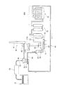
図1は、本発明の第一実施形態としての廃棄物焼却処理装置の概要構成を示しており、家庭そして産業界から収集された廃棄物を貯留する廃棄物ピット10、廃棄物を焼却する廃棄物焼却炉20、廃棄物焼却炉から排出される排ガスを無害化する無害化処理装置30、無害化された排ガスを大気に放出する排ガス放出装置40を主として備えている。この廃棄物焼却処理装置は、さらに、廃棄物ピット10からの廃棄物を廃棄物焼却炉20へもたらす前に破砕する破砕装置50、破砕廃棄物を受けて一時係留しこれを排ガスとの熱交換で加熱してから廃棄物焼却炉20へ供給する中間係留部60をも有している。また、無害化処理装置30の排ガス出口部は排ガスライン(管路)80によって排ガス放出装置40としての煙突41に接続されており、上記排ガスライン80の途中位置に既述の中間係留部60が配置されている。以下、各装置について、順次説明する。
FIG. 1 shows a schematic configuration of a waste incineration processing apparatus as a first embodiment of the present invention, a
収集された廃棄物を貯留している廃棄物ピット10と、該廃棄物ピット10から廃棄物の一部を順次受ける中間係留部として形成される係留槽60の間の位置には、破砕装置50が配設されていて、上記廃棄物ピット10からの廃棄物が、該破砕装置50で破砕されてから係留槽60へ送られるようになっている。この破砕装置50では、個々の廃棄物自体が大きい場合は粗破砕され、個々の廃棄物自体は小さくともそれらが袋体に入れられている場合には、袋体が破裂されて袋体の内部から廃棄物が分散して出てくるようになる。
A crushing
破砕された廃棄物を受ける係留槽60は、槽本体61の底部にスクリュコンベア62を有し、該底部で後述の廃棄物焼却炉20の廃棄物投入口22へ送出装置63により接続されていると共に、排ガスライン80が接続されている。また該係留槽60はその上部で、後述の排ガス放出装置40をなす煙突41に誘引ファン42を介して接続されている。かくして、係留槽60では、廃棄物が、排ガスライン80から係留槽60内へ送入される排ガスと直接接触して熱交換することで、排ガスの保有熱によって加熱され水分率が低下しあるいは乾燥した状態で、上記スクリュコンベア62によって送出装置63を経て廃棄物焼却炉20の廃棄物投入口22へ投入される。排ガスライン80からの排ガスは、係留槽60内の廃棄物を加熱して自らは降温して誘引ファン42により煙突41へ導かれ大気へ放出される。上記係留槽60における廃棄物と排ガスとの熱交換は、図示の例では直接接触としたが、間接接触であってもよい。
The
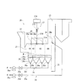
廃棄物焼却炉20は、図2に示されているように、燃焼室21と、この燃焼室21に対して廃棄物の流れ方向の上流側(図1の左側)上方に配置された、廃棄物を燃焼室21内に投入するための廃棄物投入口22と、燃焼室21に対して廃棄物の流れ方向の下流側(図1の右側)の上方に連設された廃熱ボイラ23とを備える火格子式の焼却炉である。本実施形態において、燃焼室内での廃棄物の移動方向における燃焼室の上流側を前部、下流側を後部という。
As shown in FIG. 2, the
燃焼室21の底部には、廃棄物を上流から下流側へ向け移動させながら燃焼させる火格子(ストーカ)24が設けられている。この火格子24は、廃棄物投入口22に近い方から、すなわち、上流側から乾燥火格子24a、燃焼火格子24b、後燃焼火格子24cの順に設けられている。
At the bottom of the
乾燥火格子24a上では主として廃棄物の乾燥と着火が行われる。燃焼火格子24b上では主として廃棄物の熱分解、部分酸化が行われ、熱分解により発生した可燃性ガスと固形分の燃焼が行われる。後燃焼火格子24c上では、僅かに残った廃棄物中の未燃分を完全に燃焼させる。完全に燃焼した後の燃焼灰は、燃焼室21の下流端下部に設けられた灰落下口25より排出される。
Wastes are mainly dried and ignited on the dry grate 24a. On the
このような本実施形態の焼却炉20では、乾燥火格子24aと燃焼火格子24bの上に廃棄物の層が形成され、その燃焼により、燃焼室21内の空間には、廃棄物層の直上に、下記のような諸領域が形成される。
In the
乾燥火格子24aの直上方で廃棄物投入口22の下方に対応して位置する、該乾燥火格子24aの上流側範囲(前部)の上方(空間)には乾燥領域A1が形成される。
A drying region A1 is formed above (space) the upstream range (front part) of the drying grate 24a, which is positioned immediately above the drying grate 24a and below the
乾燥火格子24aの下流側範囲(後部)から燃焼火格子24bの上流側範囲(前部)の上方(空間)には燃焼開始領域A2が形成される。すなわち、乾燥火格子24aの廃棄物は、上流側範囲で乾燥され、下流側範囲で着火して、燃焼火格子24bの上流側範囲(前部)までの範囲で燃焼が開始する。
A combustion start area A2 is formed from the downstream range (rear part) of the dry grate 24a to the upper side (space) of the upstream range (front part) of the
燃焼火格子24b上の廃棄物はここで熱分解そして部分酸化が行われ、可燃性ガスが発生し、その可燃性ガスと廃棄物の固形分が燃焼する。廃棄物はこの燃焼火格子24b上で実質的に殆んど燃焼される。こうして、上記燃焼火格子24bの上方(空間)に主燃焼領域A3が形成される。
The waste on the
しかる後、僅かに残った廃棄物中の固定炭素など未燃分が後燃焼火格子24c上で完全に燃焼される。この後燃焼火格子24cの上方(空間)に後燃焼領域A4が形成される。
Thereafter, the unburned matter such as fixed carbon in the remaining waste is completely burned on the
廃棄物が焼却される場合、まず、上記係留槽60で加熱を受けて水分率が低下しても、まだ廃棄物に残っている水分の蒸発が起こり、次いで熱分解と部分酸化反応が起こり、可燃性ガスが生成し始める。ここで燃焼開始領域A2とは、廃棄物の燃焼が始まり、廃棄物の熱分解、部分酸化により可燃性ガスが生成し始める領域である。また、主燃焼領域A3とは、廃棄物の熱分解、部分酸化が行われ可燃性ガスが発生し、その可燃性ガスが火炎を伴って燃焼しているとともに廃棄物の固形分が燃焼する燃焼領域であり、火炎を伴う燃焼が完了する点(燃え切り点)までの領域である。燃え切り点より後の領域では、廃棄物中の固形未燃分(チャー)が燃焼するチャー燃焼領域(後燃焼領域A4)となる。
When the waste is incinerated, first, even if the moisture content is reduced by being heated in the
上記燃焼室21内の乾燥火格子24a、燃焼火格子24b及び後燃焼火格子24cの下部には、それぞれ風箱26a,26b,26c,26dが設けられている。ブロワ26eにより供給される燃焼用一次空気Pは、ダンパ26gが設けられた一次空気供給管26fから上記各風箱26a,26b,26c,26dを経て、各火格子24a,24b,24cを通って燃焼室21内に供給される。なお、火格子24の下から供給される燃焼用一次空気Pは、火格子24a,24b,24c上の廃棄物の乾燥及び燃焼に使われるほか、火格子24a,24b,24cの冷却作用、廃棄物の攪拌作用を有する。
上記燃焼室21の下流側上部における出口には廃熱ボイラ23が連設され、該廃熱ボイラ23の入口近傍が燃焼室21から排出されるガス中の可燃性ガスの未燃分(未燃ガスという)を燃焼する二次燃焼領域B1となっている。廃熱ボイラ23の一部である二次燃焼領域B1内で二次燃焼用ガスを吹き込み未燃ガスを二次燃焼し、この二次燃焼の後に燃焼排ガスは廃熱ボイラ23で熱回収される。熱回収された後、廃熱ボイラ23から排出された燃焼排ガスは、後述する無害化処理装置30で無害化され、排ガス放出装置40の煙突41から大気へ放出される(図1参照)。
A
このような基本構成をなす燃焼室21を有する火格子式焼却炉20において、本実施形態では、燃焼用一次空気を上記火格子24の下から上記燃焼室21内に吹き込む一次空気吹込手段と、高温ガスを燃焼室21の天井21Aから、炉長方向で燃焼室21内の燃焼開始領域A2から主燃焼領域A3までの間の任意の領域に向かって下向きに吹き込む高温ガス吹込手段と、二次燃焼用ガスを二次燃焼領域B1に吹き込む二次燃焼用ガス吹込手段とを、後述のごとく具備している。高温ガス吹込手段は、複数の高温ガス吹込口28を備え、高温ガスを廃棄物から発生する可燃性ガス及び燃焼ガスの上昇流に対向して下向きに吹き込むことにより、廃棄物層の直上によどみ領域又は循環領域を形成して平面状燃焼領域を定在させる。
In the grate-
先ず、燃焼用空気となる燃焼用一次空気Pを供給する一次空気供給系26は、図2のごとく、空気供給源からの燃焼用一次空気Pを一次空気供給管26fを経て、乾燥火格子24a、燃焼火格子24b及び後燃焼火格子24cのそれぞれの風箱26a,26b,26c,26dに分岐供給管から送り込むようになっており、上記一次空気供給管26fには、ブロワ26eそして流量調整機構としてのダンパ26gが設けられている。
First, as shown in FIG. 2, the primary
次に、高温ガス吹込手段27は、燃焼室21の外に設けられた高温ガス供給源27Aと、燃焼室21へ高温ガスQを吹き込む高温ガス吹込口28と、高温ガスQを上記高温ガス供給源27Aから上記高温ガス吹込口28へ導く管路27Bと、流量調整機構としてのダンパ27Cとを有している。
Next, the high-temperature gas blowing means 27 includes a high-temperature
高温ガス吹込口28は、燃焼室21の天井の、乾燥火格子24aの廃棄物の移動方向下流側(後部)から燃焼火格子24bまでの範囲内の火格子直上の任意位置に設けられている。図1の例では、廃棄物の移動方向すなわち焼却炉20の長さ方向で、上記乾燥火格子24aの下流側位置の火格子直上方と燃焼火格子24bの火格子直上方で3列をなして高温ガス吹込口28a,28b,28cが設けられている。
The
各高温ガス吹込口28a,28b,28cのそれぞれの列は、図3にも見られるように、焼却炉の幅方向(図1、図2にて紙面に対して直角な方向)にも複数箇所に設けられている。したがって、高温ガス吹込口28は、焼却炉の長さ方向(図1参照)と幅方向(図3参照)の複数位置に配置される。また、高温ガスQが下方に吹き込まれるように、高温ガス吹込口28の向きが定められている。かくして、高温ガスQは、乾燥火格子24aの下流側域と燃焼火格子24bの直上に形成される、燃焼開始領域A2から主燃焼領域A3に向かって吹き込まれる。
Each row of the high
さらに、二次燃焼用ガス吹込手段に関しては、二次燃焼用ガスを廃熱ボイラ23の入口近傍に相当する二次燃焼領域B1に吹き込む二次燃焼用ガス(二次空気)供給系29を備えている。二次燃焼用ガス供給系29は、二次燃焼用ガス供給源(図示せず)からの二次燃焼用ガスRを管路29aを経て、二次燃焼領域B1に設けられた二次燃焼用ガス吹込口29bに送り込むようになっており、上記管路29aには、ブロワ29cそして流量調整機構としてのダンパ29dが設けられている。二次燃焼用ガス吹込口29bは、廃熱ボイラ23の入口近傍にある二次燃焼領域B1に二次燃焼用ガスRを吹き込むように、廃熱ボイラ23の周壁に設けられている。
Further, the secondary combustion gas blowing means includes a secondary combustion gas (secondary air)
なお、本発明において、上記燃焼用一次空気、高温ガスそして二次燃焼用ガスを供給するための管路等の構成は図示したものに限定されず、焼却炉の規模、形状、用途等により適宜選択され得る。 In the present invention, the configuration of the pipeline for supplying the primary air for combustion, the high-temperature gas, and the secondary combustion gas is not limited to those shown in the drawings, and may be appropriately selected depending on the scale, shape, application, etc. of the incinerator. Can be selected.
上述のような廃棄物焼却炉20は、図1のごとく、その廃熱ボイラ23の出口がエコノマイザ70に接続されている。該エコノマイザ70自体は公知である。
As shown in FIG. 1, the
上記エコノマイザ70には、無害化処理装置が接続されており、本実施形態では無害化装置は、消石灰吹込み等による排ガス中の酸性ガスの中和のための中和装置(図示せず)とこれに接続された除塵装置30とを有している。該除塵装置30もそれ自体は公知であり、バグフィルタ等種々の形式のものが存在するが、本実施形態ではどの形式にあってもよい。
The
上記除塵装置30の排ガス出口部は排ガスライン(管路)80によって排ガス放出装置40としての煙突41に接続されており、上記排ガスライン80の途中位置に既述の係留槽60が配置されている。かくして、除塵装置30で除塵された無害化後の排ガスは、係留槽60に流入して槽内の廃棄物を貫通することで排ガスの保有熱により廃棄物の水分率を低下させてから煙突41へ至る。上記排ガスライン80は、除塵装置30の排ガス排出部近傍で分岐管80Aが設けられていて、廃棄物焼却炉20へ高温ガスを供給する高温ガス供給源27Aへ上記分岐管80Aが接続されている。その結果、排ガスライン80の排ガスの一部が該分岐管80Aを通り上記高温ガス供給源27Aを経て高温ガスの一部として高温ガス吹込口28から廃棄物焼却炉20の燃焼室21内へ吹き込まれる。したがって、上記高温ガス供給源27Aは、別途生成された高温ガスをブロワ27Dにより高温ガス供給源27Aから廃棄物焼却炉20へ供給するだけでなく、選択的に廃棄物焼却炉20からの排ガスをも高温ガスとして、廃棄物焼却炉20へ供給することができる。
The exhaust gas outlet portion of the
次に、本実施形態装置の作動の説明に先立ち、高温ガス吹込みによる燃焼安定化に関し、本発明の廃棄物焼却炉の構造により得られる効果を要約して述べておく。 Next, prior to the description of the operation of the apparatus of the present embodiment, the effects obtained by the structure of the waste incinerator of the present invention will be summarized and described regarding the stabilization of combustion by blowing high-temperature gas.
図2そして図3は、本実施形態に係る廃棄物焼却炉内の燃焼状態を示しており、これを参照して、高温ガス吹込みによる燃焼安定化に関して、廃棄物焼却炉内の燃焼状態について説明する。 2 and 3 show the combustion state in the waste incinerator according to the present embodiment. With reference to this, the combustion state in the waste incinerator is related to the combustion stabilization by blowing high-temperature gas. explain.
図2そして図3に見られるように、本実施形態に係る廃棄物焼却炉20は、燃焼室21の天井21Aに高温ガス吹込口28が炉の長さ方向のみならず炉幅方向にも複数設けられ、火格子24上の廃棄物Wを、下方からの燃焼用空気Pにより燃焼する。廃棄物Wの燃焼に際しては、天井21Aに設けられた高温ガス吹込口28から高温ガスQを下向きに吹き込み、高温ガスQと、廃棄物Wから上昇してくる可燃性ガスと燃焼ガスとの上昇流に対して衝突させ、廃棄物層W直上に流れの遅いよどみ領域又は上下方向に循環する循環領域を形成し、平面状燃焼領域(平面火炎)Eを炉幅方向、炉長方向(廃棄物の移動方向)に均一に形成する。これにより、炉幅の大きい焼却炉でも、均一で安定した燃焼が可能となる。
As shown in FIGS. 2 and 3, the
本発明の廃棄物焼却炉は、燃焼室の天井に設けた高温ガス吹込口から高温ガスを燃焼室内に下向きに吹き込み、下向きの高温ガスの流れと、廃棄物から発生した可燃性ガスと燃焼ガスとの上昇流に対して衝突させることにより、廃棄物層直上に流れの遅いよどみ領域を形成し、燃焼促進効果や燃焼安定化効果が得られる。すなわち、このように、本発明では、高温ガスを燃焼室天井から下向きに吹き込むことにより、次のような効果を得る。 The waste incinerator of the present invention blows a hot gas downward into the combustion chamber from the hot gas inlet provided on the ceiling of the combustion chamber, and the downward hot gas flow, combustible gas and combustion gas generated from the waste , A stagnation region with a slow flow is formed immediately above the waste layer, and a combustion promoting effect and a combustion stabilizing effect are obtained. That is, in the present invention, the following effects are obtained by blowing hot gas downward from the ceiling of the combustion chamber.
高温ガスを燃焼室天井から下向きに吹き込むことの効果を詳しく説明する。 The effect of blowing hot gas downward from the ceiling of the combustion chamber will be described in detail.
(1)高温ガスの顕熱と輻射により廃棄物Wの熱分解を促進する。 (1) The thermal decomposition of the waste W is promoted by the sensible heat and radiation of the high temperature gas.
(2)酸素を含んだ高温ガスの吹込みにより廃棄物Wの熱分解により発生した可燃性ガスの燃焼を促進する。 (2) The combustion of the combustible gas generated by the thermal decomposition of the waste W is promoted by blowing a high-temperature gas containing oxygen.
(3)高温ガスを燃焼室の天井21Aに設けた高温ガス吹込口28から燃焼室21内に下向きに吹き込み、高温ガスの下向きの流れと、廃棄物Wから発生する可燃性ガスと燃焼ガスとの上昇流に対して対向させ、廃棄物層直上に流れの遅いよどみ領域又は流れが上下方向に循環する循環領域を形成することにより、可燃性ガスの流れが緩やかになり、可燃性ガスが燃焼用一次空気や高温ガスによって供給される酸化剤成分と十分に混合されるため安定した燃焼が行われる。この廃棄物層直上のよどみ領域又は循環領域で可燃性ガスが安定して燃焼し平面状燃焼領域(平面火炎)が形成され、定在する。
(3) Hot gas is blown downward into the
(4)定在する平面火炎の輻射により廃棄物Wの熱分解を促進する。 (4) The thermal decomposition of the waste W is promoted by radiation of the standing flat flame.
かくして、(1)〜(4)の作用により、低空気比燃焼操業下でも廃棄物Wの燃焼を安定して行わせることができる。そして、燃焼が安定するため可燃性ガスが十分に燃焼され、焼却炉から排出される排ガス中のCO,NOxなど有害物の発生量を抑制することができる。 Thus, by the actions (1) to (4), the waste W can be stably burned even under the low air ratio combustion operation. And since combustion is stabilized, combustible gas is fully combusted and the generation amount of harmful substances, such as CO and NOx, in the exhaust gas discharged from the incinerator can be suppressed.
さらに、定在する平面火炎Eの輻射などにより廃棄物Wの熱分解を促進することができるため、火格子24に供給する廃棄物Wの量(火格子負荷)および燃焼室内に供給する廃棄物Wの熱量(火炉負荷)を大きくすることができる。このため廃棄物焼却処理量に対して燃焼室内容積を小さくすることができ、焼却炉の炉高を低くすることができ、廃棄物焼却設備をコンパクトにすることにより設備費用及び運転費用を低減することができる。 Further, since the thermal decomposition of the waste W can be promoted by radiation of the standing flat flame E or the like, the amount of the waste W supplied to the grate 24 (grate load) and the waste supplied to the combustion chamber The amount of heat of W (furnace load) can be increased. For this reason, the volume of the combustion chamber can be reduced with respect to the amount of waste incineration, the furnace height of the incinerator can be reduced, and the waste incineration equipment can be made compact, thereby reducing the equipment cost and operation cost. be able to.
図1に示す廃棄物焼却炉20は、具体的な例を示すと、廃棄物を燃焼する燃焼室21の高さが1〜3mであり、廃棄物焼却量100ton/日程度の規模の従来型焼却炉の燃焼室高さが5〜6m程度であることに比べて、1/2以下の高さである。また、この廃棄物焼却炉20の一例の容積は、90m3であり、従来型焼却炉の190m3の1/2程度以下となる。このように、燃焼室21の高さが3m以下であることと、既述した高温ガスを天井から下向きに吹き込むことにより低空気比燃焼を安定して行うことによって、火格子式廃棄物焼却炉設備をコンパクトにすることができ、設備費用、運転費用を大幅に低減できる。
A concrete example of the
次に、このような本実施形態としての廃棄物焼却処理装置における廃棄物の焼却処理要領について説明する。 Next, a waste incineration processing procedure in the waste incineration processing apparatus as the present embodiment will be described.
先ず、都市ごみ、産業廃棄物等の廃棄物が収集されて、廃棄物ピット10へ貯留される。廃棄物は、数多くの発生箇所から収集されるので、廃棄物ピット10へ投入される廃棄物は、投入の都度、水分率が高いものから低いものまでばらつきがある。また、廃棄物の形態も、大きいものから小さいものまで、そして袋体に入っているものやばらばらになっているもの、さまざまである。そこで、本実施形態では、廃棄物ピット10内の廃棄物を少量づつ、間欠的あるいは連続的に破砕装置50へ送り、該破砕装置50で適宜大きさに粗破砕した後に、中間係留部としての係留槽60へ送る。粗破砕された廃棄物は、スクリュコンベア62と送出装置63により廃棄物焼却炉20へ向け送り出されるが、それまでの間、所定時間、該係留槽60内に係留されることとなる。
First, waste such as municipal waste and industrial waste is collected and stored in the
係留槽60は、その下部で、排ガスライン80を経て廃棄物焼却炉20から送られる排ガスを受けている。この排ガスは、廃棄物焼却炉20の廃熱ボイラ23、さらにはエコノマイザ70で熱回収されているものの、依然、廃棄物の加熱乾燥には十分な保有熱を有しており、係留槽60内の廃棄物中を貫流上昇する間に廃棄物と直接接触して、廃棄物を昇温させてその水分率を低下させる。上記係留槽60内の廃棄物は破砕装置50で粗破砕されているので、排ガスとの接触面積は十分に確保されていて水分率が効率よく低下する。排ガスは廃棄物を昇温させた後、自らは降温状態となり、誘引ファン42により誘引されて煙突41へ至り、大気へ放出される。
The
排ガスライン80の排ガスは、除塵装置30の排出口側から除塵後の状態で取り出されているが、図1で一点鎖線で示されるように排ガスの一部が除塵装置30の入口側から取り出されていてもよい。その分、除塵装置30での除塵負荷が軽減するし、除塵前の排ガスであっても、上記係留槽60内での廃棄物との直接接触により水分を含む廃棄物に付着して除塵されるので、煙突41からの放出には何ら問題ない。
The exhaust gas in the
本実施形態では、係留槽60における排ガスによる廃棄物の加熱は、既述したような排ガスと廃棄物との直接接触によらずとも、間接接触でも可能である。間接接触の場合、排ガスは係留槽60内を貫通する熱交換管路内を流れることとなり廃棄物とは接触しないので、除塵という効果は得られない。したがって、間接接触の場合は、排ガスライン80からの排ガスは除塵装置30の排出口から排出された除塵後の排ガスのみが係留槽60へ送られることとするのが好ましい。
In the present embodiment, the heating of the waste by the exhaust gas in the
排ガスと廃棄物との直接接触又は間接接触により、廃棄物を加熱し乾燥して水分率を30〜40重量%にまで低減させることが好ましい。一般に都市ごみ等の廃棄物の水分率は50重量%程度であり、低位発熱量は2000kcal/kg程度であるが、水分率を30〜40重量%にまで低減し、低位発熱量を2500〜3000kcal/kgにまで上昇させることにより、燃焼室内の廃棄物の燃焼がより安定し、回収する熱エネルギーも増加するので好ましい。 It is preferable to reduce the moisture content to 30 to 40% by weight by heating and drying the waste by direct contact or indirect contact between the exhaust gas and the waste. In general, waste such as municipal waste has a moisture content of about 50% by weight and a lower heating value of about 2000 kcal / kg, but the moisture content is reduced to 30 to 40% by weight and the lower heating value is 2500 to 3000 kcal. / Kg is preferable because the combustion of the waste in the combustion chamber becomes more stable and the recovered heat energy increases.
廃棄物の水分率を赤外線センサなどの水分率計測手段により計測し、所定の水分率の範囲とするように、係留槽60に供給する排ガス流量を制御し廃棄物の加熱を制御することが好ましい。また、炉内温度や廃熱ボイラによる収熱量を計測することにより、炉内に供給された廃棄物の発熱量を算出し、発熱量を所定の範囲(例えば、2500〜3000kcal/kg)とするように、係留槽60に供給する排ガス流量を制御し廃棄物の加熱を制御するようにしてもよい。
It is preferable to control the heating of the waste by controlling the flow rate of the exhaust gas supplied to the
かくして、水分率が低下し、しかも、その水分率にばらつきがなくなった廃棄物は、廃棄物焼却炉20へ、間欠的にあるいは連続的に供給されて焼却処理される。以下、廃棄物焼却炉20での焼却の様子を、その作動の内容毎に説明する。
Thus, the waste having a reduced moisture content and no variation in the moisture content is intermittently or continuously supplied to the
<焼却状況の概要>
先ず、廃棄物が廃棄物焼却炉20の廃棄物投入口22へ投入されると、落下した廃棄物は図示しない廃棄物供給装置により燃焼室21内に供給され、乾燥火格子24a上に堆積され、各火格子の動作により、燃焼火格子24b上そして後燃焼火格子24c上へと移動し、各火格子上に廃棄物の層を形成する。各火格子は、風箱26a,26b,26c,26dを経て、燃焼用の一次空気を受けており、これにより各火格子上の廃棄物は乾燥そして燃焼される。
<Overview of incineration>
First, when waste is introduced into the
乾燥火格子24a上では主として廃棄物の乾燥と着火が行われる。すなわち、乾燥火格子24aの廃棄物は、乾燥火格子24aの上流側範囲で乾燥され、乾燥火格子24aの下流側範囲で着火して、燃焼火格子24bの上流側範囲(前部)までの範囲で燃焼が開始する。乾燥火格子24aの廃棄物の流れ方向の上流側範囲(前部)の上方には乾燥領域A1が形成される。乾燥火格子24aの下流側範囲(後部)から燃焼火格子24bの上流側範囲(前部)の上方には燃焼開始領域A2が形成される。燃焼火格子24b上では主として廃棄物の熱分解、部分酸化が行われ可燃性ガスが発生し、その可燃性ガスが火炎を伴って燃焼するとともに、廃棄物中の固形分の燃焼が行われる。燃焼火格子24bの上方に主燃焼領域A3が形成される。この主燃焼領域A3は火炎を伴う燃焼が完了する点(燃え切り点)までの領域である。燃焼火格子24b上において廃棄物の燃焼は実質的に完了する。後燃焼火格子24c上では、僅かに残った廃棄物中の固定炭素など未燃分を完全燃焼させる。燃え切り点より後の領域では、廃棄物中の固形未燃分(チャー)が燃焼し、後燃焼火格子24cの上方に後燃焼領域A4が形成される。完全燃焼した後の燃焼灰は、灰落下口25より排出される。このように廃棄物が燃焼している状態で、図2に見られるように、各火格子24a,24b,24cの直上空間には、乾燥領域A1、燃焼開始領域A2、主燃焼領域A3そして後燃焼領域A4がそれぞれ形成される。
Wastes are mainly dried and ignited on the dry grate 24a. That is, the waste of the dry grate 24a is dried in the upstream range of the dry grate 24a, ignited in the downstream range of the dry grate 24a, and up to the upstream range (front part) of the
既述のごとく、燃焼室21の出口に、廃熱ボイラ23が連設されていて、廃熱ボイラ23の入口近傍が二次燃焼領域B1となっている。したがって、燃焼室21内で発生した可燃性ガスの未燃分(未燃ガス)は、二次燃焼領域B1に導かれ、そこで二次燃焼用ガスRと混合・攪拌され、二次燃焼する。二次燃焼の後に燃焼排ガスは廃熱ボイラ23で熱回収される。熱回収された後、廃熱ボイラ23から排出された燃焼排ガスは、消石灰等による酸性ガスの中和と、活性炭によるダイオキシン類の吸着が行われた後、除塵装置30(図示せず)に送られ、中和反応生成物、活性炭、ダストなどが回収されて無害化される。上記除塵装置30で除塵され、無害化された後の燃焼排ガスは、排ガスライン80を経て、既述の係留槽60へ送られ、ここで廃棄物を昇温した後に、誘引ファン42により誘引され、煙突41から大気中に放出される。なお、上記除塵装置30としては、例えば、バグフィルタ方式、電気集塵方式等の除塵装置を用いることができる。また、除塵装置で除塵された後の排ガスの一部が、高温ガスとして高温ガス供給源27Aへ送られる。
As described above, the
次に、一次燃焼用空気、高温ガス、二次燃焼用ガスの吹込みについて詳細に説明する。 Next, the blowing of the primary combustion air, the high temperature gas, and the secondary combustion gas will be described in detail.
<燃焼用一次空気の吹込み>
燃焼用一次空気Pは、ブロワ26eから燃焼用一次空気供給管26fを通って乾燥火格子24a、燃焼火格子24b及び後燃焼火格子24cのそれぞれの下部に設けられた風箱26a,26b,26c,26dに供給された後、各火格子24a,24b,24cを通って燃焼室21内に供給される。燃焼室21」内に供給される燃焼用一次空気Pの流量は、燃焼用一次空気供給管26fに設けられた流量調節ダンパ26gにより調整され、さらに、各風箱26a,26b,26c,26dに供給される流量は、各風箱に分岐して設けられたそれぞれの供給管に備える流量調節ダンパ(図示省略)により調節される。また、風箱26a,26b,26c,26d及び燃焼用一次空気Pを供給するための燃焼用一次空気供給管26f等の構成は図示したものに限定されず、焼却炉の規模、形状、用途等により適宜選択され得る。
<Blowing primary air for combustion>
The primary combustion air P passes from the
<高温ガス吹込みによる燃焼安定化>
図2そして図3に見られるように、高温ガスが、高温ガス吹込口28を経て、燃焼開始領域A2から主燃焼領域A3までの領域に向かって吹き込まれ、廃棄物層Wに向かって下向きに吹き込まれる。火炎が存在し可燃性ガスが多く存在する領域に、高温ガスを吹き込むことが燃焼を安定させる上で好ましいため、可燃性ガスが多く存在する領域である燃焼開始領域A2から主燃焼領域A3までの領域に高温ガスを吹き込む。
<Combustion stabilization by hot gas injection>
As seen in FIGS. 2 and 3, the hot gas is blown through the
高温ガス吹込口28を経て、高温ガスを燃焼室21内の燃焼開始領域A2から主燃焼領域A3までの領域に、かつ廃棄物層W直上に向かって下向きに吹き込むことにより、図3に見られるように、下向きに吹き込まれる高温ガスは、廃棄物の熱分解・部分酸化により生じた可燃性ガスと燃焼ガスとの上昇流に対して対向し、双方のガス流れが衝突し、廃棄物層W直上に平面状の流れの遅いよどみ領域または上下方向に循環する循環領域が生じる。これらの領域はガス流れの速度が遅いため、可燃性ガスが燃焼する火炎が定在することになり、すなわち廃棄物層W直上に平面状燃焼領域(平面火炎)Eが定在し、可燃性ガスが安定して燃焼される。その結果、低空気比燃焼においてもCO,NOx、ダイオキシン類等の有害物質の発生を抑制すると共に煤の生成を抑制することができる。このため、低空気比燃焼を支障なく行うことができる。
As shown in FIG. 3, the hot gas is blown downward into the region from the combustion start region A2 to the main combustion region A3 in the
また、高温ガスの熱輻射と顕熱によって廃棄物が加熱され、熱分解・部分酸化が促進されることに加えて、廃棄物層の直上に平面状燃焼領域(平面火炎)が定在するので、この平面状燃焼領域Eからの熱輻射と顕熱によって廃棄物が加熱され、熱分解・部分酸化がさらに促進される。 In addition to the fact that wastes are heated by thermal radiation and sensible heat of high-temperature gas, and thermal decomposition and partial oxidation are promoted, a planar combustion region (planar flame) is present directly above the waste layer. The waste is heated by thermal radiation and sensible heat from the planar combustion region E, and thermal decomposition and partial oxidation are further promoted.
次に、高温ガスについてその調製、吹込口、吹込み流速・吹込量、さらには、二次燃焼用ガスの吹込みについて、順次説明する。 Next, the preparation of the high-temperature gas, the blowing port, the blowing flow velocity / blowing amount, and the blowing of the secondary combustion gas will be sequentially described.
高温ガスの吹込み流速を、燃焼室内ガス流量を炉長方向に直角な面での燃焼室内断面積で除した空塔速度の5〜20倍の流速として吹き込むことが好ましく、燃焼室内ガス流れによる影響を受けずに、上記よどみ領域または循環領域を安定して形成することができる。 It is preferable to inject the high-temperature gas flow rate as a flow rate 5 to 20 times the superficial velocity obtained by dividing the flow rate of the combustion chamber gas by the cross-sectional area of the combustion chamber in a plane perpendicular to the furnace length direction. The stagnation region or the circulation region can be stably formed without being affected.
高温ガスQの吹込み速度は、例えば、高温ガスQを送るブロワの送風量調整や管路27Bに設けた流量調整機構としてのダンパ27Cの開度を調整し高温ガスQの吹込み流量を調整することなどにより調整される。
The blowing speed of the hot gas Q is adjusted, for example, by adjusting the blowing amount of the blower that sends the hot gas Q or adjusting the opening degree of the
高温ガス吹込口28が複数ある場合、高温ガスQはそれぞれの高温ガス吹込口28a〜28cから必ずしも等流速で吹き込まれる必要はなく、焼却炉20の規模、形状、用途或いは廃棄物性状、量、廃棄物層厚さ等により、各高温ガス吹込口28a〜28cからの吹込み流速は異なるように適宜変更され得る。
When there are a plurality of high-temperature
燃焼室21で廃棄物から発生する可燃性ガスと燃焼ガスの発生量の変動に対応して、廃棄物層の直上に平面状燃焼領域を変動なく定在させるように、高温ガスQの吹込み流量を調整することが好ましい。平面状燃焼領域Eの状態が変動すると、可燃性ガスの燃焼状態が変化し燃焼排ガス中のCO濃度、酸素濃度などが変動するため、監視因子としてボイラから排出される排ガスのCO濃度、酸素濃度を計測しその変化に対応して、高温ガスQの吹込み流量を調整するようにしてもよい。
Corresponding to fluctuations in the amount of combustible gas and combustion gas generated from the waste in the
<高温ガスの調製>
高温ガス吹込口28から吹き込まれる高温ガスの温度は、100〜400℃の範囲とすることが好ましく、150〜200℃程度とすることがより好ましい。100℃未満の温度のガスを吹き込むと炉内温度が低下し、燃焼が不安定となりCO発生量が増加する。400℃を超えるガスを吹き込むと燃焼室内における火炎温度が著しく高温になり、クリンカの生成が助長されるなど問題が生じる。高温ガスの温度を150〜200℃程度とすることにより、前記の問題の発生を抑制するとともに空気を加熱するエネルギーを適切な範囲とすることができるので、より好ましい。
<Preparation of hot gas>
The temperature of the hot gas blown from the hot
また、高温ガスQの含有する酸素濃度は5〜30体積%程度、望ましくは5〜15体積%とすることが好ましい。これにより、上述の効果がより効果的に発揮され、排ガスの低NOx化、低CO化がより促進される。 The oxygen concentration contained in the high temperature gas Q is about 5 to 30% by volume, preferably 5 to 15% by volume. Thereby, the above-mentioned effect is exhibited more effectively, and the reduction of NOx and the reduction of CO of exhaust gas is further promoted.
上記のガス温度及び酸素濃度となるような高温ガスQとしては、二次燃焼領域B1から下流側で排ガスの一部を抜き出し返送した返送排ガス、返送排ガスと空気の混合ガス、酸素を含有するガス、空気及び酸素富化空気のうちいずれかを用いることが好適である。返送排ガスとしては、廃棄物焼却炉から排出された排ガスを除塵、中和処理した排ガス、すなわち、図1に見られるように除塵装置30から排出される排ガスの一部を返送して用いることが好ましい。返送排ガス、返送排ガスと空気の混合ガス、酸素を含有するガス、空気及び酸素富化空気のうちいずれかを必要に応じて廃熱ボイラ23で発生させた蒸気により加熱して、温度と酸素濃度が上記所定の条件を満たすような高温ガスとして燃焼室21内に吹き込む。
As the high-temperature gas Q having the above gas temperature and oxygen concentration, a part of the exhaust gas is extracted downstream from the secondary combustion region B1 and returned, a mixed gas of the returned exhaust gas and air, and a gas containing oxygen. It is preferable to use any one of air and oxygen-enriched air. As the return exhaust gas, the exhaust gas discharged from the waste incinerator is dust-removed and neutralized, that is, as shown in FIG. 1, a part of the exhaust gas discharged from the
高温ガスを調製する際の返送排ガスと空気の混合割合や、返送排ガス又は返送排ガスと空気の混合ガス等の加熱条件などを調整して、高温ガスの温度、酸素濃度を所望の範囲とする。 By adjusting the mixing ratio of the return exhaust gas and air when preparing the high temperature gas, the heating conditions such as the return exhaust gas or the return exhaust gas and air mixed gas, etc., the temperature and oxygen concentration of the high temperature gas are adjusted to the desired ranges.
<高温ガスの吹込み領域>
図2において、高温ガス吹込口28は、燃焼室21内の燃焼開始領域A2から主燃焼領域A3に相当する乾燥火格子24aの上方及び燃焼火格子24bの上方において、燃焼室21の天井21Aに設置されている。ここで、廃棄物の熱分解反応は温度が200℃程度で起こり、温度が400℃程度となった段階でほぼ完了する。高温ガスQを可燃性ガスが生成している領域において、燃焼室21の天井21Aから廃棄物層直上に向かって下向きに吹き込むことにより、炉内の廃棄物層直上付近によどみ領域又は循環領域を形成させ、平面状燃焼領域を定在させて、安定した燃焼が行われる。
<High-temperature gas blowing area>
In FIG. 2, the
図2に示す例では、乾燥火格子24aの下流部及び燃焼火格子24bの上方は燃焼開始領域A2から主燃焼領域A3に相当するので、これらの位置の上方に高温ガス吹込口28を設けて高温ガスQを吹き込んでいる。廃棄物の組成、性状によっては、もっと高い温度で熱分解反応が完了するものがあり、この場合は、図2に示す位置より下流側(図の右側)にも、高温ガス吹込口を設けることが好ましい。
In the example shown in FIG. 2, the downstream part of the dry grate 24a and the upper part of the
<高温ガス吹込口>
高温ガス吹込口28は、燃焼室21の天井21Aの、乾燥火格子24aの廃棄物の移動方向下流側(後部)から燃焼火格子24bまでの範囲内での火格子直上の任意位置に設けられている。高温ガス吹込口28は、燃焼室21の幅方向と長さ方向との複数の列にそって配置される。高温ガス吹込口28は、ノズル型でもスリット型でもよい。
<High temperature gas inlet>
The
高温ガス吹込口28の配置位置、配置数、配置間隔、吹込み方向、吹込口の形状(吹き込まれた高温ガスQの広がり形状に関係する)、高温ガスQの吹込み流速、吹込み流量などの高温ガス吹込口28の設定及び操作条件は、廃棄物焼却炉の処理量、容積、形状、廃棄物の性状などに合わせ、平面状燃焼領域Eの状態を所望の状態に制御するように設定又は調整される。
Arrangement position, arrangement number, arrangement interval, blowing direction, blowing port shape (related to the shape of the blown hot gas Q), hot gas Q blowing flow rate, blowing flow rate, etc. The setting and operating conditions of the high-
燃焼室21内の廃棄物層直上で幅方向と長さ方向の広い範囲に亘って平面状燃焼領域Eが形成されるように、廃棄物からの上昇流と対向させる高温ガスの流れの状況を好ましい状態に制御するように、高温ガス吹込口28の配置位置、配置数、配置間隔、吹込み方向、吹込口の形状、高温ガスの吹込み流速及び吹込み流量のうち少なくとも一つを、設定又は調整する。
The state of the flow of the high-temperature gas facing the upward flow from the waste so that the planar combustion region E is formed over a wide range in the width direction and the length direction immediately above the waste layer in the
図2においては、燃焼室21の天井21Aに高温ガス吹込口28を設け、ここから廃棄物層に向かって下向きに高温ガスQを吹き込んでいる。ここで、高温ガスQの吹込み方向としては、廃棄物層に対する垂線から20°までの角度範囲の吹込み方向で吹き込まれることが望ましい。これは、吹き込んだ高温ガスQと、廃棄物の熱分解・部分酸化によって生じる可燃性ガスと燃焼ガスの上昇流とが衝突して生じる流れ場を対向流場とするためであり、高温ガスBの吹込み方向が廃棄物層に対する垂線から20°より大きい範囲となると、適切な対向流場が形成されなくなるためである。
In FIG. 2, a hot
<二次燃焼用ガスの吹込み>
二次燃焼用ガスRが二次燃焼領域B1に吹き込まれ、燃焼室21からの未燃ガスが二次燃焼される。二次燃焼用ガスRとして、温度は常温〜200℃の範囲であり、酸素濃度は15〜21体積%の範囲のガスを用いることが好ましい。二次燃焼用ガスとして、空気、酸素を含有するガス、返送排ガスを用いてよいし、これらの混合ガスを用いてもよい。
<Injection of secondary combustion gas>
The secondary combustion gas R is blown into the secondary combustion region B1, and the unburned gas from the
上記二次燃焼用ガスの吹込口29bは、二次燃焼領域B1内に旋回流が生じる方向に二次燃焼用ガスRを吹き込めるように1つ又は複数設置することが好ましい。二次燃焼用ガスRを二次燃焼領域B1内に旋回流が生じる方向に吹き込むことにより、二次燃焼領域B1内のガス温度及び酸素濃度分布を均一化、平均化でき、未燃ガスの二次燃焼が安定して行われ、局所高温領域の発生を抑制し、排ガスのさらなる低NOx化が可能となる。さらに、未燃ガスと酸化剤との混合が促進されるため燃焼安定性が向上し、完全燃焼が達成できるため、排ガスの低CO化も可能となる。
It is preferable to install one or more secondary
二次燃焼用ガスRとしては、ブロワにより供給される燃焼用二次空気のみ、ブロワ供給後の燃焼用二次空気に希釈剤を混合し酸素濃度を調整したガス、除塵装置を通過した後の排ガスの一部を抜き出した返送排ガスのみ、又は上記燃焼用二次空気と返送排ガスを混合したガス等を用いることができる。 As the secondary combustion gas R, only the secondary air for combustion supplied by the blower, the gas in which the diluent is mixed with the secondary air for combustion after the blower is supplied and the oxygen concentration is adjusted, after passing through the dust removing device Only the return exhaust gas from which a part of the exhaust gas is extracted, or a gas in which the secondary air for combustion and the return exhaust gas are mixed can be used.
希釈剤としては、窒素、二酸化炭素などが考えられる。 Diluents such as nitrogen and carbon dioxide are conceivable.
上記二次燃焼領域B1内のガス温度が、800〜1050℃の範囲となるように、上記二次燃焼用ガスの流量を調整することが好ましい。二次燃焼領域B1内のガス温度が800℃未満となると未燃ガスの燃焼が不十分となり、排ガス中のCOが増加する。また、二次燃焼領域B1内のガス温度が1050℃を超えると二次燃焼領域B1内におけるクリンカの生成が助長され、さらに、NOxが増加する。 It is preferable to adjust the flow rate of the secondary combustion gas so that the gas temperature in the secondary combustion region B1 is in the range of 800 to 1050 ° C. When the gas temperature in the secondary combustion region B1 is less than 800 ° C., the combustion of the unburned gas becomes insufficient, and the CO in the exhaust gas increases. Moreover, when the gas temperature in secondary combustion area | region B1 exceeds 1050 degreeC, the production | generation of clinker in secondary combustion area | region B1 will be promoted, and also NOx will increase.
以上説明したように、本発明によれば、廃棄物ピットからの廃棄物を中間係留部で排ガスを利用して水分率を低下させると共に、水分率にばらつきをなくすこととしたので、焼却炉での廃棄物の燃焼が安定すると共に、燃焼室への高温ガス吹き込みにより、燃焼室内の廃棄物層直上付近に安定なよどみ領域又は循環領域を形成させることができ、平面状燃焼領域を定在させ、廃棄物焼却炉の大きさにかかわらず、空気比が1.5以下の低空気比燃焼を行った場合においても、燃焼室内の幅方向と長さ方向の全域に亘って燃焼の安定性が維持され、COやNOx等の有害ガスの発生量が低減できる廃棄物焼却処理装置及び廃棄物焼却処理方法が提供される。さらに、従来よりさらに低空気比で燃焼を行えるので焼却炉から排出される排ガス総量をさらに大幅に低減でき、また、廃熱の回収効率を向上できる廃棄物焼却処理装置及び廃棄物焼却処理方法が提供される。 As described above, according to the present invention, the waste from the waste pit is reduced in the moisture content by using the exhaust gas in the intermediate mooring section, and the moisture content is not varied. In addition to stable combustion of waste, a high-temperature gas blown into the combustion chamber can form a stable stagnation region or circulation region in the vicinity of the waste layer in the combustion chamber. Regardless of the size of the waste incinerator, even when low air ratio combustion with an air ratio of 1.5 or less is performed, the combustion stability is stable over the entire width direction and length direction in the combustion chamber. A waste incineration processing apparatus and a waste incineration processing method are provided that can be maintained and reduce the generation of harmful gases such as CO and NOx. Furthermore, since the combustion can be performed at a lower air ratio than before, the total amount of exhaust gas discharged from the incinerator can be further greatly reduced, and a waste incineration processing apparatus and a waste incineration processing method that can improve the recovery efficiency of waste heat are provided. Provided.
また、定在する平面火炎の輻射などにより廃棄物の熱分解を促進することができるため、火格子に供給する廃棄物の量(火格子負荷)および燃焼室内に供給する廃棄物の熱量(火炉負荷)を大きくすることができる。このため廃棄物焼却処理量に対して燃焼室内容積を小さくすることができ、焼却炉の炉高を低くすることができ、廃棄物焼却設備をコンパクトにすることにより設備費用及び運転費用を低減することができる。 In addition, the thermal decomposition of waste can be promoted by radiation of standing flat flames, etc., so the amount of waste supplied to the grate (grate load) and the amount of waste supplied to the combustion chamber (furnace Load) can be increased. For this reason, the volume of the combustion chamber can be reduced with respect to the amount of waste incineration, the furnace height of the incinerator can be reduced, and the waste incineration equipment can be made compact, thereby reducing the equipment cost and operation cost. be able to.
次に、本発明の第二実施形態について説明する。図1に示された第一実施形態では、中間係留部を廃棄物ピットそして廃棄物焼却炉に対して独立して設けていたが、本実施形態では、廃棄物ピット内の空間を仕切って中間ピットとして中間係留部が形成されている点に特徴がある。図4に示す本実施形態は、上記中間ピットが廃棄物ピットの空間の一部で形成されている点、破砕装置を有していない点において、図1の第一実施形態と相違しているが、他においては図1と同じであるので、共通部分には同一符号を付してその説明は省略する。 Next, a second embodiment of the present invention will be described. In the first embodiment shown in FIG. 1, the intermediate mooring portion is provided independently for the waste pit and the waste incinerator. However, in this embodiment, the space in the waste pit is partitioned to be intermediate. It is characterized in that an intermediate mooring part is formed as a pit. This embodiment shown in FIG. 4 is different from the first embodiment of FIG. 1 in that the intermediate pit is formed in a part of the waste pit space and does not have a crushing device. However, since the other portions are the same as those in FIG. 1, common portions are denoted by the same reference numerals and description thereof is omitted.
図4に示す第二実施形態においては、廃棄物ピット10は仕切壁11により該廃棄物ピット10内の空間を仕切ることで、大空間の主ピット12と中間係留部として小空間の中間ピット13を形成している。該中間ピット13には、その底壁に排ガスライン80が接続され、該排ガスライン80にブロワ81が設けられている。かくして、排ガスライン80からの排ガスはブロワ81により中間ピット13内の廃棄物と直接接触するように該中間ピット13へ送気される。上記中間ピット13の上部空間が排ガスライン80の一部をなす排ガス管82により煙突41に接続されていて、排ガスライン80からの排ガスは、その保有熱で中間ピット13内の廃棄物と直接接触して熱交換することで該廃棄物を昇温せしめ水分率を低下させた後に自らは降温して上記煙突41から放出される。本実施形態でも、排ガスライン80からの排ガスは廃棄物と直接接触により廃棄物と熱交換するので、前実施形態の場合同様、除塵装置30への流入前、すなわち除塵前の状態で、図4の一点鎖線のごとく、除塵装置30の入口側から排ガスの一部を上記中間ピット13へ送気することができる。
In the second embodiment shown in FIG. 4, the
かかる図4の実施形態にあっては、主ピット12内の廃棄物は連続的あるいは間欠的に少量づつ中間ピット13へ移送される。該中間ピット13内の廃棄物は、該廃棄物中を貫流上昇する排ガスと直接接して該排ガスの保有熱により昇温して水分率が低下する。水分率が低下した廃棄物は、廃棄物焼却炉20へ廃棄物投入口22を経て投入される。上記中間ピット13で廃棄物と直接接触して廃棄物を昇温させる排ガスは、除塵前のダストが含有されていても、廃棄物との直接接触により、ダストは廃棄物に付着してしまい、除塵後の状態で煙突41から放出される。中間ピット13内に廃棄物を攪拌する羽部車など攪拌手段を設け、排ガスと廃棄物との熱交換を促進するようにしてもよい。
In the embodiment of FIG. 4, the waste in the
廃棄物ピット10を、仕切壁11により中間ピット13を形成する場合、中間ピット13内の廃棄物は排ガスライン80からの排ガスとの熱交換により昇温せしめられる際、排ガスと間接接触するようになっていてもよい。図5のように排ガスライン80から排ガスを受ける伝熱管83が排ガスライン80の一部として中間ピット13内に配されていて、排ガスが該伝熱管83を経て煙突41へ誘導させるようにすることができる。この場合、伝熱管83は、廃棄物との接触面積を大きくする目的で、管路を屈曲して管長を長くしたり、あるいはフィンを設けておくことが有効である。
When the
10 廃棄物ピット
13 中間係留部(中間ピット)
20 廃棄物焼却炉
21 燃焼室
24 火格子
26 一次空気吹込手段(一次空気供給系)
28 高温ガス吹込手段(高温ガス吹込口)
30 無害化処理装置(除塵装置)
40 排ガス放出装置
60 中間係留部(係留槽)
A2 燃焼開始領域
A3 主燃焼領域
10
20
28 Hot gas blowing means (hot gas blowing port)
30 Detoxification processing equipment (dust removal equipment)
40 Exhaust
A2 Combustion start area A3 Main combustion area
Claims (5)
廃棄物焼却炉は、火格子上で廃棄物を燃焼する燃焼室と、燃焼用一次空気を火格子の下から燃焼室へ吹き込む一次空気吹込手段と、火格子上の廃棄物の移動方向である炉長方向で、上記燃焼室内の燃焼開始領域から主燃焼領域までの間の任意の領域に向けて燃焼室の天井から高温ガスを下向きに吹き込む高温ガス吹込手段とを備え、
廃棄物ピットと廃棄物焼却炉との間の位置に、廃棄物ピットからの廃棄物の一部を受けて一時係留する中間係留部が設けられ、
排ガスラインが、無害化処理装置における排ガス流入部位置そして排ガス流出部位置の少なくとも一方の位置で、上記中間係留部に接続されており、排ガスが上記中間係留部内の廃棄物と熱交換後に排ガス放出装置から放出されるようになっていることを特徴とする廃棄物焼却処理装置。 A waste pit that receives and stores the collected waste, a grate-type waste incinerator that incinerates the waste from the waste pit, and a detoxification that makes the exhaust gas from the waste incinerator harmless In a waste incineration treatment apparatus having a treatment apparatus and an exhaust gas emission apparatus that discharges the detoxified exhaust gas to the atmosphere, and connected by an exhaust gas line from the waste incinerator to the exhaust gas emission apparatus,
The waste incinerator is a combustion chamber for burning waste on a grate, primary air blowing means for blowing combustion primary air from below the grate into the combustion chamber, and the movement direction of the waste on the grate A high-temperature gas blowing means for blowing a high-temperature gas downward from the ceiling of the combustion chamber toward an arbitrary region between the combustion start region and the main combustion region in the combustion chamber in the furnace length direction;
An intermediate mooring section is provided at a position between the waste pit and the waste incinerator for temporarily mooring a part of the waste from the waste pit,
An exhaust gas line is connected to the intermediate mooring portion at at least one of an exhaust gas inflow portion position and an exhaust gas outflow portion position in the detoxification treatment apparatus, and the exhaust gas is discharged after exchanging heat with the waste in the intermediate mooring portion. A waste incineration apparatus characterized by being discharged from the apparatus.
燃焼用一次空気を火格子下から上記燃焼室内に吹き込み、
火格子上の廃棄物の移動方向である炉長方向で上記燃焼室内の燃焼開始領域から主燃焼領域までの間の任意の領域に向け高温ガスを上記燃焼室の天井から下向きに吹き込み、
廃棄物ピットと廃棄物焼却炉との間の位置に設けられた中間係留部へ、廃棄物ピットからの破棄物の一部を係留し、
無害化処理装置における排ガス流入部位置そして排ガス流出部位置の少なくとも一方の位置からの排ガスを上記中間係留部内の廃棄物と熱交換させた後に排ガス放出装置から放出することを特徴とする廃棄物焼却処理方法。 A waste pit that receives and stores the collected waste, a grate-type waste incinerator that incinerates the waste from the waste pit, and a detoxification that makes the exhaust gas from the waste incinerator harmless A waste incineration process in a waste incineration treatment apparatus having a treatment apparatus and an exhaust gas emission apparatus for releasing the detoxified exhaust gas to the atmosphere and connected by an exhaust gas line from the waste incinerator to the exhaust gas emission apparatus In the method
Blow primary air for combustion into the combustion chamber from below the grate,
High-temperature gas is blown downward from the ceiling of the combustion chamber toward an arbitrary region between the combustion start region and the main combustion region in the combustion chamber in the furnace length direction, which is the moving direction of waste on the grate,
A part of the waste from the waste pit is moored to an intermediate mooring section located between the waste pit and the waste incinerator,
Waste incineration characterized in that the exhaust gas from at least one of the exhaust gas inflow portion position and the exhaust gas outflow portion position in the detoxification treatment device is discharged from the exhaust gas discharge device after heat exchange with the waste in the intermediate mooring portion. Processing method.
Priority Applications (1)
| Application Number | Priority Date | Filing Date | Title |
|---|---|---|---|
| JP2014090081A JP2015209992A (en) | 2014-04-24 | 2014-04-24 | Waste incineration treatment equipment and waste incineration treatment method |
Applications Claiming Priority (1)
| Application Number | Priority Date | Filing Date | Title |
|---|---|---|---|
| JP2014090081A JP2015209992A (en) | 2014-04-24 | 2014-04-24 | Waste incineration treatment equipment and waste incineration treatment method |
Publications (1)
| Publication Number | Publication Date |
|---|---|
| JP2015209992A true JP2015209992A (en) | 2015-11-24 |
Family
ID=54612322
Family Applications (1)
| Application Number | Title | Priority Date | Filing Date |
|---|---|---|---|
| JP2014090081A Pending JP2015209992A (en) | 2014-04-24 | 2014-04-24 | Waste incineration treatment equipment and waste incineration treatment method |
Country Status (1)
| Country | Link |
|---|---|
| JP (1) | JP2015209992A (en) |
Cited By (2)
| Publication number | Priority date | Publication date | Assignee | Title |
|---|---|---|---|---|
| JP2021156492A (en) * | 2020-03-27 | 2021-10-07 | 株式会社プランテック | Vertical waste incinerator and waste incineration amount adjustment method for the same |
| WO2023085241A1 (en) * | 2021-11-12 | 2023-05-19 | 三菱重工業株式会社 | Waste treatment facility |
-
2014
- 2014-04-24 JP JP2014090081A patent/JP2015209992A/en active Pending
Cited By (2)
| Publication number | Priority date | Publication date | Assignee | Title |
|---|---|---|---|---|
| JP2021156492A (en) * | 2020-03-27 | 2021-10-07 | 株式会社プランテック | Vertical waste incinerator and waste incineration amount adjustment method for the same |
| WO2023085241A1 (en) * | 2021-11-12 | 2023-05-19 | 三菱重工業株式会社 | Waste treatment facility |
Similar Documents
| Publication | Publication Date | Title |
|---|---|---|
| JP6011295B2 (en) | Waste incinerator and waste incineration method | |
| JP6824642B2 (en) | Waste incineration equipment and waste incineration method | |
| JP5818093B2 (en) | Waste incinerator and waste incineration method | |
| JP2016191539A (en) | Stoker type waste incinerator and waste incineration method | |
| JP6146673B2 (en) | Waste incinerator and waste incineration method | |
| JP2004084981A (en) | Waste incinerator | |
| JP5861880B2 (en) | Waste incinerator and waste incineration method | |
| WO2013133290A1 (en) | Grate-type waste incinerator and method for incinerating waste | |
| JP5800237B2 (en) | Waste incinerator and waste incineration method | |
| JP6256859B2 (en) | Waste incineration method | |
| JP2015209992A (en) | Waste incineration treatment equipment and waste incineration treatment method | |
| JP5871207B2 (en) | Waste incinerator and waste incineration method | |
| JP2013164226A (en) | Waste material incinerator and waste material incinerating method | |
| JP3956862B2 (en) | Combustion control method for waste incinerator and waste incinerator | |
| JP6146671B2 (en) | Waste incinerator and waste incineration method | |
| JP7035356B2 (en) | Waste incinerator and waste incinerator method | |
| JP6218117B2 (en) | Grate-type waste incinerator and waste incineration method | |
| JP6455717B2 (en) | Grate-type waste incinerator and waste incineration method | |
| JP6090578B2 (en) | Waste incinerator and waste incineration method | |
| JP2005226970A (en) | Fire grate type waste incinerator and its operation method | |
| JP6183787B2 (en) | Grate-type waste incinerator and waste incineration method | |
| JP6443758B2 (en) | Grate-type waste incinerator and waste incineration method | |
| JP6008187B2 (en) | Waste incinerator and waste incineration method | |
| JP6103471B2 (en) | Waste incinerator and waste incineration method | |
| JP6146672B2 (en) | Waste incinerator and waste incineration method |