JP5799162B2 - Truck system for wind power generator - Google Patents
Truck system for wind power generator Download PDFInfo
- Publication number
- JP5799162B2 JP5799162B2 JP2014504879A JP2014504879A JP5799162B2 JP 5799162 B2 JP5799162 B2 JP 5799162B2 JP 2014504879 A JP2014504879 A JP 2014504879A JP 2014504879 A JP2014504879 A JP 2014504879A JP 5799162 B2 JP5799162 B2 JP 5799162B2
- Authority
- JP
- Japan
- Prior art keywords
- track
- hub
- wagon
- extension
- nacelle
- Prior art date
- Legal status (The legal status is an assumption and is not a legal conclusion. Google has not performed a legal analysis and makes no representation as to the accuracy of the status listed.)
- Expired - Fee Related
Links
- 238000000034 method Methods 0.000 claims description 38
- 230000002265 prevention Effects 0.000 claims description 16
- 238000004804 winding Methods 0.000 claims description 2
- 238000010248 power generation Methods 0.000 claims 2
- 239000011295 pitch Substances 0.000 description 25
- 230000000007 visual effect Effects 0.000 description 18
- 238000012423 maintenance Methods 0.000 description 14
- 230000008439 repair process Effects 0.000 description 5
- 239000000463 material Substances 0.000 description 4
- 230000008569 process Effects 0.000 description 4
- 238000009434 installation Methods 0.000 description 3
- 238000009423 ventilation Methods 0.000 description 3
- 238000001816 cooling Methods 0.000 description 2
- 230000007246 mechanism Effects 0.000 description 2
- 238000011144 upstream manufacturing Methods 0.000 description 2
- 229910000831 Steel Inorganic materials 0.000 description 1
- 230000009471 action Effects 0.000 description 1
- 239000000956 alloy Substances 0.000 description 1
- 229910045601 alloy Inorganic materials 0.000 description 1
- 229910052782 aluminium Inorganic materials 0.000 description 1
- XAGFODPZIPBFFR-UHFFFAOYSA-N aluminium Chemical compound [Al] XAGFODPZIPBFFR-UHFFFAOYSA-N 0.000 description 1
- 230000008901 benefit Effects 0.000 description 1
- 239000000428 dust Substances 0.000 description 1
- 239000011152 fibreglass Substances 0.000 description 1
- 229910052751 metal Inorganic materials 0.000 description 1
- 239000002184 metal Substances 0.000 description 1
- 150000002739 metals Chemical class 0.000 description 1
- 230000004048 modification Effects 0.000 description 1
- 238000012986 modification Methods 0.000 description 1
- 239000004033 plastic Substances 0.000 description 1
- 229920003023 plastic Polymers 0.000 description 1
- 239000010959 steel Substances 0.000 description 1
- 239000013585 weight reducing agent Substances 0.000 description 1
- 238000003466 welding Methods 0.000 description 1
Images


Classifications
-
- F—MECHANICAL ENGINEERING; LIGHTING; HEATING; WEAPONS; BLASTING
- F03—MACHINES OR ENGINES FOR LIQUIDS; WIND, SPRING, OR WEIGHT MOTORS; PRODUCING MECHANICAL POWER OR A REACTIVE PROPULSIVE THRUST, NOT OTHERWISE PROVIDED FOR
- F03D—WIND MOTORS
- F03D80/00—Details, components or accessories not provided for in groups F03D1/00 - F03D17/00
- F03D80/50—Maintenance or repair
-
- F—MECHANICAL ENGINEERING; LIGHTING; HEATING; WEAPONS; BLASTING
- F03—MACHINES OR ENGINES FOR LIQUIDS; WIND, SPRING, OR WEIGHT MOTORS; PRODUCING MECHANICAL POWER OR A REACTIVE PROPULSIVE THRUST, NOT OTHERWISE PROVIDED FOR
- F03D—WIND MOTORS
- F03D1/00—Wind motors with rotation axis substantially parallel to the air flow entering the rotor
- F03D1/06—Rotors
- F03D1/065—Rotors characterised by their construction elements
- F03D1/0691—Rotors characterised by their construction elements of the hub
-
- F—MECHANICAL ENGINEERING; LIGHTING; HEATING; WEAPONS; BLASTING
- F05—INDEXING SCHEMES RELATING TO ENGINES OR PUMPS IN VARIOUS SUBCLASSES OF CLASSES F01-F04
- F05B—INDEXING SCHEME RELATING TO WIND, SPRING, WEIGHT, INERTIA OR LIKE MOTORS, TO MACHINES OR ENGINES FOR LIQUIDS COVERED BY SUBCLASSES F03B, F03D AND F03G
- F05B2240/00—Components
- F05B2240/90—Mounting on supporting structures or systems
- F05B2240/91—Mounting on supporting structures or systems on a stationary structure
- F05B2240/916—Mounting on supporting structures or systems on a stationary structure with provision for hoisting onto the structure
-
- Y—GENERAL TAGGING OF NEW TECHNOLOGICAL DEVELOPMENTS; GENERAL TAGGING OF CROSS-SECTIONAL TECHNOLOGIES SPANNING OVER SEVERAL SECTIONS OF THE IPC; TECHNICAL SUBJECTS COVERED BY FORMER USPC CROSS-REFERENCE ART COLLECTIONS [XRACs] AND DIGESTS
- Y02—TECHNOLOGIES OR APPLICATIONS FOR MITIGATION OR ADAPTATION AGAINST CLIMATE CHANGE
- Y02E—REDUCTION OF GREENHOUSE GAS [GHG] EMISSIONS, RELATED TO ENERGY GENERATION, TRANSMISSION OR DISTRIBUTION
- Y02E10/00—Energy generation through renewable energy sources
- Y02E10/70—Wind energy
- Y02E10/72—Wind turbines with rotation axis in wind direction
-
- Y—GENERAL TAGGING OF NEW TECHNOLOGICAL DEVELOPMENTS; GENERAL TAGGING OF CROSS-SECTIONAL TECHNOLOGIES SPANNING OVER SEVERAL SECTIONS OF THE IPC; TECHNICAL SUBJECTS COVERED BY FORMER USPC CROSS-REFERENCE ART COLLECTIONS [XRACs] AND DIGESTS
- Y02—TECHNOLOGIES OR APPLICATIONS FOR MITIGATION OR ADAPTATION AGAINST CLIMATE CHANGE
- Y02E—REDUCTION OF GREENHOUSE GAS [GHG] EMISSIONS, RELATED TO ENERGY GENERATION, TRANSMISSION OR DISTRIBUTION
- Y02E10/00—Energy generation through renewable energy sources
- Y02E10/70—Wind energy
- Y02E10/728—Onshore wind turbines
Landscapes
- Engineering & Computer Science (AREA)
- Life Sciences & Earth Sciences (AREA)
- Sustainable Development (AREA)
- Sustainable Energy (AREA)
- Chemical & Material Sciences (AREA)
- Combustion & Propulsion (AREA)
- Mechanical Engineering (AREA)
- General Engineering & Computer Science (AREA)
- Wind Motors (AREA)
- Connection Of Motors, Electrical Generators, Mechanical Devices, And The Like (AREA)
Description
本開示は、風力発電装置用のトラックシステムに関する。 The present disclosure relates to a truck system for a wind turbine generator.
欧州特許出願公開第2363598号明細書に記載されるように、タワーに回転可能に配置され、第1キャビティを有するナセルと、ナセルの上流側に配置され、第2キャビティを有する発電機収容部と、発電機収容部の上流側に配置され、ロータブレードが取り付けられるとともに第3キャビティを有するハブとを備える風車が知られている。これらの第1、第2及び第3キャビティは互いに連通している。レールシステムは、全てのキャビティを通るように延在し、3つのレール要素を含んでいる。このレールシステムは、吊り上げ及び/又は搬送のための手段、特にメンテナンス時における風車の組立部品のための手段をさらに備えている。吊り上げ及び/又は搬送のための手段は、レールシステムに沿って移動可能となっている。これにより、発電機収納部を通ってハブへ部品を移動できるようになっている。3つのレール要素は、レールシステムの長さを延長させるものでもある。レール要素のうちナセル内に位置する第1レールの後端は、ハッチによって開閉される第1開口を介して風車の外側へ延長可能となっている。 As described in EP 2363598 A, a nacelle rotatably disposed on a tower and having a first cavity, a generator housing having a second cavity disposed upstream of the nacelle, and There is known a windmill that is disposed on the upstream side of a generator housing portion and has a rotor blade attached and a hub having a third cavity. These first, second and third cavities communicate with each other. The rail system extends through all cavities and includes three rail elements. The rail system further comprises means for lifting and / or transporting, in particular means for the wind turbine assembly during maintenance. The means for lifting and / or transporting is movable along the rail system. As a result, the parts can be moved to the hub through the generator housing. The three rail elements also extend the length of the rail system. The rear end of the 1st rail located in a nacelle among rail elements can be extended to the outside of a windmill via the 1st opening opened and closed by a hatch.
また、代替となる積載用開口はハブの自由端にも配置されており、風車上部の一方の端部の外部からハブ、発電機収容部及びナセルを通って風車の反対側の端部までレールシステムを延長させることもできる。 An alternative loading opening is also located at the free end of the hub, from the outside of one end of the windmill through the hub, generator housing and nacelle to the opposite end of the windmill. The system can be extended.
レールシステムの長さの延長は、テレスコープ式機構によって実現される。このテレスコープ式機構は、レールエレメントの第1レールを、レールエレメントの第2レール内の静止位置からナセルの後端側、さらにはナセルの外部へ、最終的な延長の状態に達するまでスライドさせるようになっている。ハブ内へのレールシステムの長さの延長は、レールエレメントの第2レールにレールエレメントの第3レールを取り付けて、ねじ又は溶接によって安定した連結を形成することによって達成される。 Extension of the length of the rail system is realized by a telescopic mechanism. This telescopic mechanism slides the first rail of the rail element from the rest position in the second rail of the rail element to the rear end side of the nacelle and further to the outside of the nacelle until the final extension state is reached. It is like that. Extending the length of the rail system into the hub is accomplished by attaching a third rail of the rail element to the second rail of the rail element to form a stable connection by screws or welding.
さらに、クレーン及びホイストシステムが、レールシステムに連結可能なナセル及び発電機収容部の外面に配置されている。クレーン及びホイストシステムは、第3の積載用開口を介して、吊り上げ及び/又は搬送のための手段に連結されてもよく、これにより巻き上げられた又は持ち上げられた構成部材の移動方向等の自由度を向上させている。クレーン及びホイストシステムは、風車の外面、すなわちナセル及び発電機収容部の外面におけるクレーン及びホイストの軸方向移動を許容する第2レールシステムに着脱自在に取り付けられていてもよい。その結果、クレーン及びホイストシステムを、風車のメンテナンスのときにのみ取り付けることができる。第3積載用開口は、回動可能なハッチによって閉鎖可能である。 In addition, a crane and hoist system are disposed on the outer surface of the nacelle and generator housing that can be coupled to the rail system. The crane and hoist system may be connected to the means for lifting and / or transporting via the third loading opening, and thereby the degree of freedom such as the direction of movement of the components that have been rolled up or lifted Has improved. The crane and hoist system may be detachably attached to a second rail system that allows axial movement of the crane and hoist on the outer surface of the wind turbine, that is, the outer surface of the nacelle and the generator housing. As a result, the crane and hoist system can only be installed during windmill maintenance. The third loading opening can be closed by a rotatable hatch.
欧州特許出願公開第2363598号明細書に記載される更なるバリエーションによれば、吊り上げ及び/又は搬送のための手段は伸縮可能となっている。そのため、吊り上げ及び/又は搬送のための手段は、風車の運転中は収縮した状態にあり、メンテナンス作業等の間は非収縮状態にある。 According to a further variation described in EP 2363598, the means for lifting and / or transporting can be extended and retracted. Therefore, the means for lifting and / or transporting is in a contracted state during operation of the windmill, and is in a non-contracted state during maintenance work or the like.
欧州特許出願公開第2363598号明細書に記載される風車においては、発電機収納部を介してナセルからハブ内部へ連通する直通路の存在が前提とされている。しかしながら、幾つかの風車の構成においてはこれは提供されていない。 In the wind turbine described in the specification of European Patent Application No. 2363598, it is assumed that there is a straight passage communicating from the nacelle to the inside of the hub through the generator housing. However, this is not provided in some windmill configurations.
本発明の少なくとも幾つかの実施形態は、上述の問題を回避し、特にナセルからハブ内部への直通路が存在しない場合においても、よりフレキシブルな搬送手段を提供可能な風力発電装置用のトラックシステムを提供することを目的とする。 At least some embodiments of the present invention avoid the above-mentioned problems, and in particular, when there is no direct passage from the nacelle to the inside of the hub, a truck system for a wind turbine generator that can provide a more flexible conveying means The purpose is to provide.
この課題を解決するために、本発明の幾つかの実施形態にかかる風力発電装置用のトラックシステムは、
タワーの先端部に取り付けられたナセルと、
回転軸回りに回転可能であり、且つ、前記回転軸の周囲に放射状に配置される複数のロータブレードに接続されたハブと、
前記ハブの外側のうち、隣り合う2つの前記ロータブレードの間の前方部分から前記ナセルに対向する前記ハブの後方部分までの領域に取り付けられた少なくとも一つのトラックと、
前記少なくとも一つのトラックを走行するように構成され、部品搬送に適したワゴンと、を備えることを特徴とする。
In order to solve this problem, a truck system for a wind turbine generator according to some embodiments of the present invention includes:
A nacelle attached to the top of the tower,
A hub connected to a plurality of rotor blades rotatable around a rotation axis and arranged radially around the rotation axis;
At least one track attached to a region from the front part between the two adjacent rotor blades to the rear part of the hub facing the nacelle outside the hub;
A wagon configured to travel on the at least one truck and suitable for parts conveyance is provided.
これにより、少なくとも一つのトラックを、予め定められた通路に沿ったワゴンの案内に適したガイド手段として用いることができる。このワゴンは、トラックシステムの少なくとも一つのトラックに対して、少なくとも沿うように荷を移動するのに適した手段としてみなされる。ここで言及される荷とは、風力発電装置周辺、特にハブ周辺において、具体的には風力発電装置及びその構成部品の取り付け、修理又はメンテナンスの目的で移動されるどのようなものであってもよい。好ましくは、この荷は、風力発電装置又はその構成機器から取り除かれた、あるいは取り外された部品であったり、交換部品及び部品取付けや修理やメンテナンスのための工具であったりしてもよい。なお、風力発電装置(Wind turbine generators)は、一般的に、風車(wind
turbines)又は風力エネルギー変換装置(wind energy converters)とも呼ばれることがある。
Thereby, at least one track can be used as guide means suitable for guiding the wagon along a predetermined passage. This wagon is regarded as a suitable means for moving the load at least along the at least one truck of the truck system. A load referred to herein is anything that is moved around a wind turbine generator, particularly around a hub, specifically for the purpose of installing, repairing or maintaining the wind turbine generator and its components. Good. Preferably, the load may be a part that has been removed or removed from the wind turbine generator or its components, or may be a replacement part and a tool for mounting, repairing, and maintenance. Wind turbine generators are generally used for wind turbines.
sometimes called turbines) or wind energy converters.
本発明の幾つかの実施形態に係るトラックシステムによれば、ナセル又はその周辺からハブの前方部分へ、容易且つ安全に、荷(特に重い荷)を移動させることができ、好ましくはハブの内部へ簡単な方法によって荷を搬入可能である。これにより、ナセルからハブ内部への直通路が存在しない場合であっても、容易且つ安全に荷の移動を実行できる。これは、その作業中における制限をなくし、風力発電装置建設のための自由度の向上につながる。 The truck system according to some embodiments of the present invention allows a load (especially a heavy load) to be easily and safely moved from the nacelle or its periphery to the front part of the hub, preferably inside the hub. It is possible to carry in loads by a simple method. Thereby, even if there is no direct passage from the nacelle to the inside of the hub, the load can be easily and safely moved. This eliminates the restrictions during the work and leads to an increase in the degree of freedom for constructing the wind turbine generator.
本発明の実施形態において、前記少なくとも一つのトラックは、一又は複数のレールを含む。この実施形態では、一又は複数のレールは、案内部材としてみなされるものであり、好ましくは、ワゴンを移動及び案内するための予め定められた通路に沿って延在している。特に、一又は複数のレールは、従来の方式によって形成されてもよい。すなわち、一又は複数のレールは、各種の形状の断面を有していてもよいし、例えば鋼、アルミニウム、これらの又は他の金属を含む合金若しくは混合材のような各種の材料によって形成されていてもよい。また、ガラス繊維強化プラスチック又は同様のプラスチックから形成されていてもよい。さらに、少なくとも一つのトラックは、各種のレールから形成されてもよい。最も好ましくは、少なくとも一つのトラックは、後述するように2本又は4本のレールから形成されていてもよい。 In an embodiment of the present invention, the at least one track includes one or more rails. In this embodiment, the rail or rails are to be considered as guide members and preferably extend along a predetermined path for moving and guiding the wagon. In particular, the one or more rails may be formed in a conventional manner. That is, the one or more rails may have cross sections of various shapes, and are formed of various materials such as steel, aluminum, alloys containing these or other metals, or mixed materials. May be. It may also be formed from glass fiber reinforced plastic or similar plastic. Furthermore, at least one track may be formed from various rails. Most preferably, the at least one track may be formed from two or four rails as described below.
さらなる実施形態において、前記ナセルに取り付けられるとともに前記少なくとも一つのトラックに接続された第1拡張トラックをさらに備える。これにより、部品取付けや修理やメンテナンスの際に、トラックシステムの移動経路を容易且つ簡素にナセル内まで延設することができ、構成部品やその他部品等の荷を容易且つ安全にナセル内へ搬入又はナセル内から搬出することができる。そのため、荷の移動や修理やメンテナンス等の作業が容易に且つより有利に行える。しかしながら、円滑な風力発電装置の運転のために、ハブの外部における第1拡張トラックと少なくとも一つのトラックとの接続は、メンテナンス作業等の間のみ維持するようにしてもよい。 In a further embodiment, further comprising a first extension track attached to the nacelle and connected to the at least one track. This makes it possible to easily and simply extend the movement path of the truck system into the nacelle when mounting, repairing, or maintaining parts, and to easily and safely load components and other parts into the nacelle. Or it can carry out from the inside of a nacelle. Therefore, operations such as load movement, repair, and maintenance can be performed easily and more advantageously. However, for smooth operation of the wind turbine generator, the connection between the first extension truck and the at least one truck outside the hub may be maintained only during maintenance work or the like.
好ましくは、後述するように一実施形態において、前記少なくとも一つのトラック及び前記第1拡張トラックは、前記ナセルのハウジングの前方に配置されたマンホールの領域において、前記マンホールを通って延在する共通トラックを形成するために接続可能である。このように、風力発電装置における部品取付けや修理やメンテナンスの際に、マンホールは、作業員の通路として利用されるのみでなく、交換部品や工具等の移動にも用いられる。このマンホールは、特にナセルのハウジングからハブの外部への通路を形成するように、ナセルのハウジングに設けられる。 Preferably, as will be described later, in one embodiment, the at least one track and the first extension track are a common track extending through the manhole in a region of a manhole disposed in front of the housing of the nacelle. Can be connected to form. In this way, the manhole is used not only as a passage for workers but also for moving replacement parts, tools, and the like during component mounting, repair, and maintenance in the wind turbine generator. The manhole is provided in the nacelle housing, in particular so as to form a passage from the nacelle housing to the outside of the hub.
幾つかの実施形態において、前記ハブの前記前方部分に移動可能に配置されるとともに前記ハブの前記前方部分の前記少なくとも一つのトラックに接続するように構成された少なくとも一つの第2拡張トラックをさらに備える。少なくとも一つの第2拡張トラックは、ハブの前方周辺においてワゴンによって荷を安全且つ容易に移動させることを許容する。また、第1拡張トラックとの組み合わせによって、ナセルからハブの前方部分への移動又はその逆の移動を実現可能である。これは、前方部分に開口(特に換気目的の開口)を有するハブを考慮した場合に特に望ましい形態であり、本発明の実施形態においてナセル及びハブ内部の間における前記開口を介した移動を目的として付加的に用いられるものである。 In some embodiments, further comprising at least one second extension track movably disposed on the front portion of the hub and configured to connect to the at least one track of the front portion of the hub. Prepare. At least one second extension truck allows the load to be safely and easily moved by the wagon around the front of the hub. Moreover, the movement from the nacelle to the front part of the hub or the reverse movement can be realized by the combination with the first extension track. This is a particularly desirable form when considering a hub having an opening (especially an opening for ventilation) in the front portion, and for the purpose of movement through the opening between the nacelle and the interior of the hub in an embodiment of the present invention. It is used additionally.
この目的のために、本発明のさらなる実施形態に係るトラックシステムにおいて、前記少なくとも一つの第2拡張トラックは、前記少なくとも一つの第2拡張トラックを前記ハブの前記前方部分へ接続するためのヒンジを有するヒンジ付きトラックである。これは、少なくとも一つの第2拡張トラックの少なくとも一つのトラックシステムへの簡素な接続を許容する。この接続は、容易に取付け可能且つ着脱可能であって、例えば風力発電装置の運転中における換気を目的とした前方開口の使用を阻害しないために、少なくとも一つの第2拡張トラックはハブの前方開口から取り外すことができる。 For this purpose, in a track system according to a further embodiment of the invention, the at least one second extension track comprises a hinge for connecting the at least one second extension track to the front part of the hub. A hinged track having This allows a simple connection of at least one second extension track to at least one track system. This connection is easily attachable and detachable and does not obstruct the use of the front opening for ventilation purposes, for example during operation of the wind power plant, so that the at least one second extension truck has a front opening in the hub. Can be removed from.
好ましくは、少なくとも一つの前記少なくとも一つの第2拡張トラックは、前記ハブの前方開口の領域に取り付けられている。これは、特に、少なくとも一つの第2拡張トラックが、ハブの前方開口又はその近傍に取り付けられていることを意味する。 Preferably, at least one of the at least one second extension track is attached to a region of the front opening of the hub. This means in particular that at least one second extension track is attached at or near the front opening of the hub.
一実施形態に係るトラックシステムでは、前記少なくとも一つのトラック若しくは前記少なくとも一つの第2拡張トラックが前記ハブへの磁性アタッチメントを有しているか、又は、前記第1拡張トラックが前記ナセルへの磁性アタッチメントを有している。他の実施形態では、前記少なくとも一つのトラック若しくは前記少なくとも一つの第2拡張トラックが前記ハブへのボルト締結アタッチメントを有している。これらの異なる種類のアタッチメントの提供により、部品取付け時及び運転時において、容易なハンドリング性を許容しながら、硬固且つ簡素なアタッチメントを採用できる。特に、磁性アタッチメントは、トラックシステムの部品の迅速な着脱が可能である。多くの場合、風力発電装置においてトラックシステムが永続的に必要とされる訳ではないため、部品取付けや修理やメンテナンスの必要性が生じた場合に、風力発電装置へトラックシステムを容易に取り付けることができ、その作業が終了したら取り外すことができる。これは、コスト及び重量の削減にも寄与する。 In one embodiment, the at least one track or the at least one second extension track has a magnetic attachment to the hub, or the first extension track has a magnetic attachment to the nacelle. have. In another embodiment, the at least one track or the at least one second extension track has a bolt fastening attachment to the hub. By providing these different types of attachments, it is possible to adopt a rigid and simple attachment while allowing easy handling during component mounting and operation. In particular, the magnetic attachment can quickly attach and detach the components of the track system. In many cases, wind trucks do not require a truck system permanently, so it is easy to install the truck system on a wind farm when there is a need for component installation, repair or maintenance. Yes, you can remove it when you are done. This also contributes to cost and weight reduction.
他の実施形態において、前記トラックからの前記ワゴンの脱線を回避するための脱線防止ガード配列を備える。特に、ハブに形成されるコースのようにトラックは水平なコースではないことがあるため、この実施形態により、トラックに沿ったワゴンの安全な移動を可能としている。 In another embodiment, a derailment prevention guard arrangement for avoiding derailment of the wagon from the truck is provided. In particular, this embodiment allows for safe movement of the wagon along the track, as the track may not be a horizontal course like the course formed in the hub.
さらなる実施形態において、前記脱線防止ガード配列は、互いに一定の距離となるように配置された少なくとも一対のローラを含み、前記少なくとも一対のローラの間に、前記少なくとも一つのトラックのレールが配置されている。このように、少なくとも一対のロータのそれぞれは各レールを囲むように配置され、これによりトラックシステムの少なくとも一つのトラック上でワゴンが保持される。勿論、第1拡張トラック又は少なくとも一つの第2拡張トラックもそれぞれ同様の構成を有していてもよい。 In a further embodiment, the derailment prevention guard arrangement includes at least a pair of rollers arranged at a certain distance from each other, and the rails of the at least one track are arranged between the at least one pair of rollers. Yes. Thus, each of the at least one pair of rotors is arranged to surround each rail, thereby holding the wagon on at least one track of the track system. Of course, the first extension track or at least one second extension track may have the same configuration.
最も好ましくは、上述の実施形態のように脱線防止ガード配列を備える場合も、少なくとも一つのトラック、第1拡張トラック及び少なくとも一つの第2拡張トラックが2本のレールから形成される簡素な配置構成であってもよい。 Most preferably, even when the derailment prevention guard arrangement is provided as in the above-described embodiment, the simple arrangement configuration in which at least one track, the first extension track, and the at least one second extension track are formed from two rails. It may be.
本発明の実施形態に係るトラックシステムにおいて、前記少なくとも一つのトラック、前記第1拡張トラック又は前記少なくとも一つの第2拡張トラックは、互いに一定の距離で配置された少なくとも2本のレールを含んでおり、前記脱線防止ガード配列は、前記少なくとも2本のレールの間に配置された複数のローラを含んでいる。この実施形態において、互いに一定の距離を介して配置される少なくとも2本のレールは、各ローラを囲むように配置される。これにより、ワゴンの構成を簡素化することができる。 In the track system according to the embodiment of the present invention, the at least one track, the first extension track, or the at least one second extension track includes at least two rails arranged at a certain distance from each other. The derailment prevention guard arrangement includes a plurality of rollers disposed between the at least two rails. In this embodiment, at least two rails arranged at a certain distance from each other are arranged so as to surround each roller. Thereby, the structure of a wagon can be simplified.
脱線防止ガード配列が、互いに一定の距離を介して配置される少なくとも2本のレールから形成される場合、少なくとも一つのトラックは4本のレールから形成される。しかしながら、この実施形態の変形例として、互いに一定の距離を介して配置される2本のレール配列の代わりに、具体的には互いに一定の距離を介して配置される2本の分離されたレールを採用してもよい。その場合、好ましくは一本のレールの断面が、前記ローラを挟むように配置される端部と、これらの端部に接続される中間部とを含む2つの部位を有している。このように、レールが、例えばU型形状を有するように形成されていてもよい。 When the derailment prevention guard arrangement is formed from at least two rails arranged at a certain distance from each other, at least one track is formed from four rails. However, as a variant of this embodiment, instead of two rail arrangements arranged at a fixed distance from each other, specifically two separate rails arranged at a fixed distance from each other May be adopted. In that case, the cross section of one rail preferably has two portions including an end portion arranged so as to sandwich the roller and an intermediate portion connected to these end portions. Thus, the rail may be formed to have, for example, a U shape.
他の実施形態に係るトラックシステムは、前記少なくとも一つのトラック、前記第1拡張トラック又は前記少なくとも一つの第2拡張トラックに沿って前記ワゴンを移動させるように構成されたワゴン移動手段をさらに備える。これらのワゴン移動手段によれば、重い荷を搬送する場合であっても安全、容易且つ正確にワゴンを移動させることができる。 The track system according to another embodiment further includes wagon moving means configured to move the wagon along the at least one track, the first extension track, or the at least one second extension track. According to these wagon moving means, the wagon can be moved safely, easily and accurately even when a heavy load is transported.
さらに好ましくは、前記ワゴン移動手段は、前記ナセルの内部に配置されている。また、前記ワゴン移動手段は、好ましくはウィンチ又はホイストである、電気的、機械的又は手動の巻上げ手段と、前記少なくとも一つのトラック、前記第1拡張トラック又は前記少なくとも一つの第2拡張トラックのいずれかに沿った前記ワゴンの移動のために、前記ワゴンに固定されたロープ状要素と、を含む。これにより、簡素で且つ軽量な構成で、自由度の高い利用が可能であるとともに、操作性の向上が図れる。なお、ロープ状要素としては、例えばロープ、チェーン、ケーブル、ワイヤ、ベルト又はコードが挙げられる。 More preferably, the wagon moving means is disposed inside the nacelle. The wagon moving means is preferably an electric, mechanical or manual hoisting means, preferably a winch or a hoist, and any of the at least one track, the first extension track, or the at least one second extension track. A rope-like element secured to the wagon for movement of the wagon along the crab. Thus, with a simple and lightweight configuration, it can be used with a high degree of freedom, and operability can be improved. In addition, as a rope-shaped element, a rope, a chain, a cable, a wire, a belt, or a cord is mentioned, for example.
トラックに沿ったワゴンのより安全で容易な操作のために、他の実施形態では、前記ワゴンに固定されたロープ状安全要素をさらに備え、前記ロープ状安全要素は、前記ワゴンの移動を制御するように構成されている。ロープ状安全要素としては、例えばロープ、チェーン、ケーブル、ワイヤ、ベルト又はコードが挙げられる。 For a safer and easier operation of the wagon along the track, in another embodiment, it further comprises a rope-like safety element fixed to the wagon, the rope-like safety element controlling the movement of the wagon. It is configured as follows. Examples of rope-like safety elements include ropes, chains, cables, wires, belts or cords.
他の実施形態に係るトラックシステムは、前記ワゴン、又は、前記ナセル内において前記ワゴンにより搬送される部品を昇降するためのクレーンをさらに備える。好ましくは、このクレーンは、ナセルに取り付けられ、ナセルのハウジング内での利用に適している。しかし、具体的にはナセルのハウジングに形成された積載用開口等を介したナセルの外部における搬送を目的として用いられてもよい。これにより、簡素に、広範囲に且つ効率的に、荷及び/又はワゴンの搬送を行うことができる。 The track system according to another embodiment further includes a crane for raising and lowering the wagon or a component conveyed by the wagon in the nacelle. Preferably, the crane is attached to the nacelle and is suitable for use in the nacelle housing. However, it may be used for the purpose of conveyance outside the nacelle through a loading opening or the like formed in the nacelle housing. Thereby, a load and / or a wagon can be conveyed simply and widely.
上述の目的を達成するために、本実施形態に係る風力発電装置は、
タワーの先端部に取り付けられるナセルと、
回転軸回りに回転可能であり、且つ、前記回転軸の周囲に放射状に配置された複数のロータブレードに接続されたハブと、
前記ハブの外側のうち、隣り合う2つの前記ロータブレードの間の前方部分から前記ナセルに対向する前記ハブの後方部分までの領域に取り付けられた少なくとも一つのトラック、及び、前記少なくとも一つのトラックを走行するように構成され、部品搬送に用いられるゴンを含むトラックシステムと、を備えることを特徴とする。
In order to achieve the above object, the wind turbine generator according to the present embodiment is
A nacelle attached to the tip of the tower;
A hub connected to a plurality of rotor blades capable of rotating about a rotation axis and radially arranged around the rotation axis;
Out of the hub, at least one track attached to a region from a front portion between two adjacent rotor blades to a rear portion of the hub facing the nacelle, and the at least one track And a truck system including a gon configured to travel and used for parts conveyance.
さらなる実施形態において、上述した風力発電装置は、少なくとも主に前記ハブを囲むように設けられたスピナーをさらに備え、前記スピナーの内部に、前記ワゴンが前記少なくとも一つのトラックに沿って部品移動可能なように、前記トラックシステムにおける少なくとも一つのトラックに形成されたトンネル形状の空間が設けられている。 In a further embodiment, the wind power generator described above further includes a spinner provided at least mainly to surround the hub, and the wagon is movable within the spinner along the at least one track. As described above, a tunnel-shaped space formed in at least one track in the track system is provided.
トンネル形状の空間は、ワゴンの通路を形成する。このトンネル形状の空間は、ハブの外側で且つスピナーの内側に形成される。荷は、ワゴンによってトンネル形状の空間をハブの外表面に沿って搬送される。好ましくは、ワゴン及び荷が少なくとも一つのトラックに沿って通過可能なように、ハブを囲むように該ハブのハウジングを形成するスピナーには、トラックシステムの少なくとも一つのトラックの上方に一又は複数の適切な突出部が設けられている。トンネル形状の空間は例えば一又は複数の突出部の下方に設けられ、大型の荷であっても円滑にトラック上を通過可能なように一又は複数の突出部が形成される。この構成により、トラックシステムの効果的な保護が可能である。すなわち、搬送される荷やトラックシステムの作業員を外部環境から保護できる。特に、風力発電装置が洋上に設置される場合には重要なことである。 The tunnel-shaped space forms a wagon passage. This tunnel-shaped space is formed outside the hub and inside the spinner. The load is transported along the outer surface of the hub by a wagon through a tunnel-shaped space. Preferably, the spinner that forms the housing of the hub so as to surround the hub so that the wagon and load can pass along the at least one track includes one or more of the track system above the at least one track. Appropriate protrusions are provided. The tunnel-shaped space is provided below, for example, one or a plurality of protrusions, and one or a plurality of protrusions are formed so that even a large load can smoothly pass over the track. With this configuration, it is possible to effectively protect the track system. That is, it is possible to protect the load being transported and the truck system worker from the external environment. This is particularly important when the wind power generator is installed on the ocean.
好ましくは、トラックシステムの少なくとも一つのトラック上に設けられた一又は複数の突出部を含むスピナー材の少なくとも一部が、トラックシステムの少なくとも一つのトラックの側方で、スピナーの他の部位から着脱自在な分割構造部材として形成される。これにより、付加的に、トラックシステムの少なくとも一つのトラックに対するスピナーの外部からのアクセス性の向上や極めて大型の荷の搬送性の向上が図れる。 Preferably, at least a portion of the spinner material including one or more protrusions provided on at least one track of the track system is detachable from other parts of the spinner on the side of at least one track of the track system. It is formed as a freely divided structural member. As a result, it is possible to improve the accessibility from the outside of the spinner to at least one track of the track system and the transportability of extremely large loads.
上述の実施形態に関連して、ナセルとハブ外部の間の通路を形成するためのマンホールがナセルに設けられていている。これにより、ナセルのハウジングから好ましくはスピナーの内部までの通路が形成される。 In relation to the above-described embodiment, a manhole is provided in the nacelle for forming a passage between the nacelle and the outside of the hub. This forms a passageway from the nacelle housing to preferably the interior of the spinner.
上述の目的は、上述のようなトラックシステムを用いた方法によって達成される。ブレードがY字ポジションに配置されるようなハブの姿勢において、一以上のトラックが設けられ、ハブの最上部に位置するトラックが構成部品の搬送に用いられる。ここで、ブレードのY字ポジションは、ハブに3本のロータブレードが好ましくは120°の間隔で取り付けられ、ブレードの一つが直下に向いて、上方に向く他の2本のロータの間のハブの部位が真上に位置するときに実現される。すなわち、ブレードのY字ポジションは、2つの隣り合うロータブレードの間に位置するハブの部位が上方に位置するときに実現されるものである。 The above object is achieved by a method using a track system as described above. One or more tracks are provided in the hub position where the blades are arranged at the Y-position, and the track positioned at the top of the hub is used for conveying the components. Here, the Y position of the blade is such that three rotor blades are attached to the hub, preferably at an interval of 120 °, with one of the blades pointing directly down and between the other two rotors facing upwards. This is realized when the part of is located directly above. In other words, the Y-position of the blade is realized when the hub portion located between two adjacent rotor blades is located above.
本発明の実施形態に係るトラックシステムには各種の配置構成が存在し、上述の方法により実行される。コスト削減効果及び簡素化を考慮した構成とする場合、トラックシステムは、それぞれの又は隣り合う2本のロータブレードの間の隙間又は空間のうち一つに沿って、ハブの前方部分からナセルに対向するハブの後方へ向けて該ハブの外側に取り付けられた一本のトラックを含む。その場合、他の隙間又は空間にはトラックは存在しない。但し、これは一つの明瞭なロータポジションの場合にのみ利用可能なトラックシステムである。一方、風力発電装置の部品取付けや補修やメンテナンスの幾つかの場合、例えば一又は複数のブレードのピッチ駆動モータの取付けや補修やメンテナンスなどにおいては、他のポジション、特にY字ポジションの他のポジションでロータを停止することもある。これにより、2つ以上、好ましくは2本の隣り合うロータブレードの間のそれぞれの隙間又は空間に、複数のトラックが設けられる。 Various arrangements exist in the track system according to the embodiment of the present invention, and are executed by the above-described method. When configured for cost savings and simplification, the truck system faces the nacelle from the front portion of the hub along one of the gaps or spaces between each or two adjacent rotor blades. And a single track attached to the outside of the hub toward the rear of the hub. In that case, there are no tracks in other gaps or spaces. However, this is a track system that can only be used with one distinct rotor position. On the other hand, in some cases of parts installation, repair and maintenance of the wind power generator, for example, in the installation, repair and maintenance of the pitch drive motor of one or more blades, other positions, particularly other positions of the Y-position. Sometimes the rotor stops. This provides a plurality of tracks in each gap or space between two or more, preferably two adjacent rotor blades.
さらに、上述のトラックシステムを用いた一実施形態における方法において、前記ワゴンが走行するように構成された前記少なくとも一つの第2拡張トラックは、好ましくは前記ハブの内部に配置された前記ハブの構成部品又は前記ハブの代替部品である部品の移動に用いられる。これにより、ナセルからハブの内部への荷の搬送通路を形成でき、簡素且つ容易に搬送作業を行える。 Further, in the method according to the embodiment using the above-described track system, the at least one second extension truck configured to travel the wagon preferably has a configuration of the hub disposed inside the hub. It is used to move parts or parts that are substitute parts of the hub. Thereby, the conveyance path | route of the load from the nacelle to the inside of a hub can be formed, and conveyance work can be performed simply and easily.
要約すると、上述のトラックシステムによれば、ナセル内のクレーンを用いることなく、ハブ又はスピナーの内部で構成部品を搬送できる。これにより、スピナー及びナセルの内部を外部環境へ露出する必要がなくなる。そのため、構成部品を常に保護された状況下におき、且つ、構成部品の落下を回避することができる。 In summary, the truck system described above allows components to be transported within a hub or spinner without using a crane in the nacelle. This eliminates the need to expose the interior of the spinner and nacelle to the external environment. Therefore, it is possible to always keep the component under a protected condition and to prevent the component from falling.
以下、本発明の実施形態を、次の概略的な図面を参照して説明する。
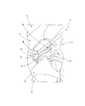
図1は、本実施形態における風力発電装置40のロータ41の中央部の縦断面を第1視野方向から視た斜視図である。ロータ41は、風力発電装置40の発電機シャフト31に取り付けられたハブ30を含む。本実施形態では、発電機シャフト31はスリーブシャフトとして形成されているが、他の各種のシャフトを採用することもできる。ハブ30は、発電機シャフト31の回転軸と一致した回転軸を中心として回転可能となっている。なお、この回転軸は、発電機シャフト31の中心に位置し、長手方向に延在するものである。以下、風力発電装置40、及び、本発明に記載された実施形態に関して重要な風力発電装置40の構成部品について、図1及び他の図を参照して詳細に説明する。
FIG. 1 is a perspective view of a longitudinal section of a central portion of a
ハブ30には、回転軸の周囲に放射状に配置される複数のロータブレードが取り付けられる。一実施形態では3本のロータブレードが設けられているが、図1に例示されるロータブレードは、符号32及び33でそれぞれ示される第1ロータブレード及び第2ロータブレードのみが部分的に示されている。第3ロータブレード34は、図1では省略している。第3ロータブレード34の一部は、以下の図5に示している。
The
この実施形態において、ハブ30は、少なくともスピナー35によって大部分が覆われている。スピナーは、発電機シャフト31の周辺におけるハブ30の後方部位と、ロータブレードブレード32,33,34が取り付けられる部位とを除くハブの全ての部位を覆っている。図2及び図3に示すように、スピナーはナセル50に隣接して配置され、ハブ30の一部がナセル50に対向している。こうして、ハブ30及びハブ30に取り付けられる全ての構成部品が天候から保護されている。
In this embodiment, the
図1に示す実施形態において、ハブ30は、少なくとも大部分が回転軸について中央に配置された前方開口36を備えている。特に、風力発電装置40の運転時において、前方開口36は、風力発電装置40の冷却に用いられる空気流を吸引する。前方開口36は、具体的には風力発電装置40に含まれる発電機機器の冷却に用いられる。この目的のために、さらに前方開口36は、ハブ30の回転軸に沿ってスピナー35の前方部分に延在するエアダクト37に接続されている。さらにまた、エアダクト37の前部は、スピナー35の前方開口38に接続されている。そして、スピナー35の前方開口38からハブ30の内部まで、エアダクト37及びハブ30の前方開口36を空気が流れるようになっている。さらに、エアダクト37は、空気流を制御するとともに空気流に含まれる塵埃や水分をフィルタリングするフィルター換気ユニット39を含んでいる。
In the embodiment shown in FIG. 1, the
一実施形態において、図1に示す風力発電装置40のロータ41は、トラックシステム100をさらに備えている。添付図面に示すように、一実施形態に係るトラックシステム100は、複数のトラック101,102,103を含んでいる。各トラック101,102,103は、ハブの外部に取り付けられている。各トラック101,102,103は、それぞれ、ハブ30の前方部分からナセル50に対向するハブ30の後方部分へ向けて、ロータブレード32,33,34のうち隣り合う2本の間のハブの表面に沿って延在している。具体的に、これらのトラックのうち第1トラック101は、隣接する第1ロータブレード32及び第3ロータブレード34の間において、ハブ30の前方部分、すなわちハブ30の前方開口36の端部から、ナセル50に対向するハブ30の後方部分まで延在している。同様に、図4に示すように、これらのトラックのうち第2トラック102は、隣接する第1ロータブレード32及び第2ロータブレード33の間において、ハブ30の前方開口36の端部からハブ30の後方部分まで延在している。また、図3に示すように、これらのトラックのうち第3トラック103は、隣接する第2ロータブレード33及び第3ロータブレード34の間において、ハブ30の前方開口36の端部からハブ30の後方部分まで延在している。
In one embodiment, the
トラックシステムは、ナセル50に取り付けられる第1拡張トラック104をさらに備えている。ロータ41の停止位置において、第1拡張トラック104は、第1トラック101、第2トラック102及び第3トラック103のそれぞれに一つずつ接続される。好ましくは、第1拡張トラック104は、例えば風力発電装置40のメンテナンス時などのトラックシステム100による移動が実施される時に取り付けられるように、ナセル50に対して着脱自在に取り付けられる。その後、風力発電装置40の運転が開始される前に取り外される。ハブ30及びハブ30に取り付けられるトラック101,102,103は、風力発電装置40の運転時にナセル50に対して回転するため、トラック101,102,103のそれぞれと第1拡張トラック104との間が風力発電装置40の運転時に接続されていることは適切ではない。
The track system further includes a
好ましくは、トラック101,102,103のそれぞれと第1拡張トラック104とは、ナセル50のハウジング52の前方51に形成されたマンホール(不図示)の領域において接続されている。第1トラック101,第2トラック102又は第3トラック103はそれぞれマンホールの一方に位置し、第1拡張トラック104はマンホールの他方に位置し、これによりマンホールを介して延在する共通トラックが形成される。このように、ナセル50のハウジング52からハブ50の外部へ、及び、有利にはそこからハブ30を囲みハウジングを形成するスピナー35の内部へ通路が形成される。このようにして、周囲環境から保護される移動通路は、ハブ30の前方開口36からナセル50のハウジングの内部まで延在するトラックシステムを構成している。
Preferably, each of the
一実施形態に係るトラックシステム100は、3本の第2拡張トラックをさらに備えている。第2拡張トラックは、ハブ30の前方部分、特にハブ30の前方開口36の端部に、移動可能に配置されている。第2拡張トラックのそれぞれは、ハブ30の前方部分において、第1トラック101、第2トラック102及び第3トラック103のそれぞれに一つずつ接続されている。特に、一番目の第2拡張トラック105は、トラックシステム100の第1トラック101に接続されている。同様に、二番目の第2拡張トラック(不図示)は、トラックシステム100の第2トラック102に接続されており、三番目の第2拡張トラック107は、トラックシステム100の第3トラック103に接続されている。
The
第2拡張トラック105,107は、ヒンジ付トラックによって形成されている。第2拡張トラック105,107は、ハブ30の前方部分に形成された前方開口36の端部に対して第2拡張トラック105,107(勿論、不図示の二番目の第2拡張トラックも同様である)を締結するためのヒンジを有している。このヒンジによって、第2拡張トラックは、ハブの前方開口36の領域に回動自在に取り付けられ、前方開口36に直接的に又は前方開口36の前に位置するように回動可能となっている。この位置において、各第2拡張トラックは、ハブ30の外部において、トラックシステムのそれぞれのトラック101,102,103に接続される。好ましくは、第2トラックの一本のみが、それぞれのトラック101,102,103に接続され、他の2つの第2拡張トラックは、好ましくはハブ30の内部のパーキング位置に配置される。図1には、一番目の第2拡張トラック及び三番目の第2拡張トラックがそれぞれのパーキング位置に配置された場合を例示している。
The second extension tracks 105 and 107 are formed by hinged tracks. The second extension tracks 105 and 107 are the same as the second extension tracks 105 and 107 (of course, the second extension track not shown) with respect to the end of the
一実施形態において、トラックシステム100のトラック101,102,103及び第2拡張トラックは、着脱可能にハブ30に取り付けられる。そのため、トラックシステム100の着脱を容易化する目的から、トラック101,102,103及び第2拡張トラックが、ハブ30への取り付けのための磁性アタッチメントを有していてもよい。同様に、第1拡張トラック104が、ナセル50への取り付けのための磁性アタッチメントを有していてもよい。
In one embodiment, the
上述の変形例として、トラック101,102,103及び第2拡張トラックは、ハブ30に対して永久的に取り付けられてもよい。そのため、トラックシステム100における締結のための簡素且つ硬固な取付け手段として、トラック101,102,103及び第2拡張トラックが、ハブ30への取り付けのためのボルト締結アタッチメントを有していてもよい。さらに、第1拡張トラック104も同様に、ナセル50への取り付けのためのボルト締結アタッチメントを有していてもよい。また、いくつかのトラックでは、これらの締結手段を混合して用い、一方は磁性アタッチメントによって取り付け、他方はボルト締結アタッチメントで取り付けてもよい。例えば、風力発電装置40の運転時に取り外しておく必要のあるトラックに対しては容易に着脱自在な締結手段を用い、ハブ30が回転してアタッチメントに大きな力が作用するような状況下においては、トラックを安全に固定するために硬固な締結手段を用いる。
As a modification described above, the
図2は、一実施形態に係る風力発電装置40の一部であり、図1に示す前記縦断面の切断面に沿った第2視野方向から視た平面図である。この風力発電装置40には、上述した本発明の実施形態に係るトラックシステム100が取り付けられている。以下、図2及びこれ以降の図において、既に説明した部材については共通の符号を付している。
FIG. 2 is a plan view of a part of the
図2に示すように、一実施形態に係る風力発電装置40は、一構成例におけるロータ41と、図1にて上述したロータ41の中央部分と、を備える。この実施形態に係る風力発電装置40において、ロータ41は、上述した一構成例におけるナセル50に取り付けられる。ナセル50は、具体的にはタワー(不図示)の先端に取り付けられる。風力発電装置40において、発電機シャフト31はナセル50に支持されており、発電機シャフト31の周囲においてハブ30の後方部分はナセル50、特にナセル50のハウジング52の前方に隣接している。ナセル50は、風力で駆動されるロータ41及び発電機シャフト31の回転によって発電し、電気エネルギーを供給する機器42を含んでいる。なお、機器42は本発明に対して直接的には関連しないため、風力発電装置のこれらの部位に関する詳細な説明はここでは省略する。
As shown in FIG. 2, the
好ましくはナセル50のハウジング52内における風力発電装置40の部品取付けや補修やメンテナンスの目的で、ナセル50内において、クレーン43が、例えば交換部品や工具などの昇降される荷に取り付けられる。但し、クレーン43は、ハッチ等のように一又は複数の開口が設けられている場合、ナセル50のハウジング52の外部で荷を取り扱うために用いられてもよい。その場合、ナセル50の外部に突出可能なクレーンのビームがハウジング52に備え付けられてもよい。一構成例において、クレーン43は伸縮自在なビームを有している。但し、他の構成であってもよく、例えば、関節式のアーム、ナックル式のクレーン、又は、欧州特許出願公開第2363598号明細書に記載されるように荷を吊り上げ及び/又は移動するためのレールエレメントを採用してもよい。好ましくは、クレーン43は、特に風力発電装置の運転時のように風力発電装置においてそれが不要な場合には取り外すことができるように、着脱自在にナセルに取り付けられるポータブルクレーンであってもよい。本発明の実施形態に関連したクレーン43の特定の使用については後述する。
Preferably, for the purpose of mounting, repairing, and maintaining the components of the
図3は、図2に示す風力発電装置40を、図1に示した縦断面の切断面に垂直(すなわち上述の第2視野方向に垂直)な第3視野方向から視た側面図である。図4は、図2及び図3に示す風力発電装置を、前記縦断面の切断面に関連した第4視野方向から視た斜視図である。図3及び図4に示す部品にも、上述した部品と共通の符号を付している。
FIG. 3 is a side view of the
トラックシステム100は、トラック101,102,103、第1拡張トラック104、一番目の第2拡張トラック105、二番目の第2拡張トラック及び三番目の第2拡張トラック107の走行に適したワゴン110を備えている。ワゴン110は、荷の移動、特に構成部品の移動に用いられる。
The
図5は、ワゴン110の構成例を示す概略斜視図である。原則として、この構成例におけるワゴン110は、これに取り付けられたローラ111を含むプラットホーム式ワゴンで構成される。このワゴン110は、ローラ11によって前記トラックに沿って移動するようになっている。一例として、図5には第1トラック101のみを示している。但し、ワゴン110は、第1トラック101を走行する代わりに上述した他の全てのトラックを走行可能である。
FIG. 5 is a schematic perspective view showing a configuration example of the
好ましくは、ワゴン110は、荷が滑り落ちることを防止するためのヒンジ付プレート(不図示)を備えている。さらに、ワゴン110は、例えばテンションベルト(不図示)などの形態で荷を十分に緊締するための手段を備えている。
Preferably, the
本発明の実施形態に係るトラックシステム100のトラックは、一又は複数のレールを含んでいる。図5に示す実施形態において、有利には、トラックシステム100の第1トラック101は4本のレール112,113,114,115から形成される。すなわち、符号112,113で示される一対のレールと、符号114,115で示される一対のレールが2組設けられている。第1のレール組における2本のレール112,113は、互いに一定の距離を介して配置される。同様に、第2のレール組における2本のレール114,115も互いに一定の距離を介して配置される。
The track of the
好ましくは、図示されるように一実施形態に係るトラックシステム100の他の全てのトラック、すなわち、第2トラック102、第3トラック103、第1拡張トラック104及び第2拡張トラック105,107は、上記と同様に互いに一定の距離を介して配置された一対のレールを2組ずつ含んでいる。このレール配置においてワゴン110のローラ111は、一対のレール112,113及び一対のレール114,115のそれぞれにおける2本のレールの間に挟持されて案内される。そして、トラック101〜107がハブ30の湾曲及び傾斜に沿っていることを考慮して、ワゴン110のトラック101〜107からの脱線を回避しながらワゴン110が傾斜した通路に沿って案内されるようになっている。こうして、一対のレール112,113及び一対のレール114,115は、各レール組の2本のレールの間に挟持されるローラ11と共に、第1構成例における脱線防止ガード配列を形成する。
Preferably, as shown, all other tracks of the
図6は、第2実施形態に係るトラックシステム100に適用されるワゴン110の第2構成例を示す概略斜視図である。なお、第2構成例におけるワゴン110は、第2構成例に示す脱線防止ガード配列と組み合わされるものである。この実施形態において、トラック101〜107は、それぞれ、2本のレール116,117から形成される。この構成例におけるワゴン110は、一対のローラ118,119及び一対のローラ120,121を含んでいる。一対のローラ118,119及び一対のローラ120,121は、それぞれ、互いに一定の距離を介して配置されており、トラック101〜107のレール116,117のそれぞれは、一対のローラ118,119又は一対のローラ120,121の間に挟持されて配置される。このように、この構成例における脱線防止ガード配列は、2つのレールを挟むように配置された一対のローラを2組含んでいる。
FIG. 6 is a schematic perspective view showing a second configuration example of the
図7は、第3実施形態に係るトラックシステム100に適用されるワゴン110の第3構成例を示す概略斜視図である。なお、第3構成例におけるワゴン110は、第3構成例に示す脱線防止ガード配列と組み合わされるものである。ここで、トラック101〜107は、少なくとも大部分が平行に配置され、隣接した2本の断面U字状部材123から形成される。断面U字状部材123の開口は、互いに逆向きに配置される。この断面U字状部材によって、ワゴン110に取り付けられたローラ122が案内されるようになっている。こうして、ワゴンのトラック101〜107からの脱線が回避される。
FIG. 7 is a schematic perspective view showing a third configuration example of the
再び図5を参照して、概略的に示されるワゴン移動手段124は、第1トラック101、第2トラック102又は第3トラック103に沿ったワゴン110の移動、あるいは、第1拡張トラック104又は第2拡張トラック105,107に沿ったワゴン110の移動に用いられる。ワゴン移動手段124は、好ましくはウィンチ又はホイスト125である、電気的、機械的又は手動の巻上げ手段を含んでいる。ウィンチ又はホイスト125は、例えばロープやチェーン等のようなロープ状要素126を有している。ウィンチ又はホイストは、ロープ状要素126によってワゴン110を引っ張ることで移動させるようになっている。この目的のために、ワゴン110は、その前端127にロープ状要素126の接続部128を有しており、この接続部128において、ウィンチ又はホイスト125のロープ状要素126がワゴン110の前端127に固定されるようになっている。
Referring again to FIG. 5, the wagon moving means 124 shown schematically is the movement of the
好ましくは、ワゴン移動手段124のウィンチ又はホイスト125はナセル50の内部に配置される。これにより、一つのウィンチ又はホイスト125及び一つのロープ状要素126を含む一つの移動手段124によって、ワゴン110はトラックシステム100のトラック101〜107のそれぞれに沿って簡単に移動可能となる。
Preferably, the winch or hoist 125 of the wagon moving means 124 is disposed inside the
図5に示すように、本発明の一実施形態に係るトラックシステム100は、ワゴン110に固定されたロープ状安全要素129をさらに備える。このロープ状安全要素129は、ワゴンの移動の制御に用いられる。特に、この目的のために、ワゴン110はその後端130にロープ状安全要素129を固定するための第2接続部131を有している。ロープ状安全要素129は、例えばロープやチェーン等の形態で備え付けられている。ワゴン110の移動を制御するために、ロープ状要素126及びロープ状安全要素129は、ワゴン110の移動方向に対して互いに反対側に引っ張られる。そして、要素126,129のうち一つ要素の引張力を、要素126,129のうち他の要素の引張力よりも大きい適切な力として、選択された方向においてそれぞれがワゴン110を引っ張るようになっている。
As shown in FIG. 5, the
再び図1を参照して、一実施形態において、スピナー35はその側方に、トラックシステム100の第1トラック101、第2トラック102及び第3トラック103に沿って、それぞれトンネル形状の空間が設けられている。このトンネル形状の空間により、第1トラック101、第2トラック102及び第3トラック103のそれぞれに沿ってワゴン110が部品を搬送できるようになっている。トンネル形状の空間は、ハブ30の外部且つスピナー35の内部に沿って、ワゴン110及びワゴンに固定された荷のための通路を形成する。これにより、簡単に且つ効果的に、周囲環境からの保護が実現できる。
Referring again to FIG. 1, in one embodiment, the
さらに、前記天候からの保護に関して改良及び簡素化するために、マンホールがナセル50のハウジング52の前方51に配置される。これにより上述の通路は、好ましくは前記マンホールを通って、ナセル50のハウジング52からハブ30の周囲でハウジングを形成するスピナー35の内部まで形成される。
In addition, a manhole is placed in
トンネル形状の空間を形成するために、スピナー35は、トラックシステム100の第1トラック101、第2トラック102及び第3トラック103のそれぞれの上部に、該トラック101,102,103に沿ったワゴン110及び荷の通過を許容するような突出部を有している。突出部下方のトンネル形状の空間及び突出部自体は、大型の荷であっても前記トラック101,102,103を困難なく通過可能なように形成される。図1において、符号140で示される突出部の下方には、第1トラック101が配置されている。同様に、他の突出部の下方には、第2トラック102及び第3トラックが配置されている。
In order to form a tunnel-shaped space, the
好ましくは、第1トラック上の突出部を含むスピナー材の少なくとも一部は、第1トラック101から外れた位置においてスピナー35の他の部位に対して着脱可能な分割構造部材として形成される。これにより、付加的に、スピナー35の外部から第1トラック101へのアクセス性を向上できるとともに、第1トラック101に沿って極めて大型の荷を移動可能となる。同様の構成が、第2トラック102及び第3トラック103に対応した突出部にも適用できる。
Preferably, at least a part of the spinner material including the protruding portion on the first track is formed as a split structural member that can be attached to and detached from other portions of the
トラック101〜107上を移動可能なワゴン110と共同して、クレーン43は、特に、ナセル50内でワゴン110又は該ワゴン110によって搬送される荷を吊り上げるために用いられる。この目的のために、ワゴン110は第1拡張トラック104に移動される。上述したように、ナセル50の外部へ突出可能なクレーンのビームがハウジング52に備え付けられ、該ハウジング52に一又は複数の開口(例えばハッチなどの開口)が設けられている場合、ワゴン110及び/又は荷は、クレーン43によってその位置から吊り上げられ、ナセル50のハウジング52の内部又は外部へ搬送されてもよい。クレーン43がワゴン110及び/又は荷を第1拡張トラック104から吊り上げた状態を図2、図3及び図4に示している。
In conjunction with the
図1に示すように、一実施形態において旋回式クレーン150はハブ30の内部に配置される。旋回式クレーン150は、主に、旋回軸を介してその一方の端部で支持フレーム153に移動可能に連結されたクレーンビーム151と、好ましくはボールジョイント152と、を含む。支持フレーム153は、発電機シャフト31に固定して取り付けられ、発電機シャフト31とともに回転可能となっている。クレーンビーム151は、その他方の端部に、荷を昇降するための手段が設けられている。図1では、風力発電装置40の運転中におけるパーキング位置の旋回式クレーン150を示している。旋回式クレーン150は、ハブ30の内部における荷の取扱い及び搬送に用いられ、特に、ワゴン110への荷の載置又はワゴン110からの荷の取り出しのための荷の昇降に用いられる。
As shown in FIG. 1, in one embodiment, the
旋回式クレーン150によって搬送される典型的な荷として、ワゴン110、ナセル内50のクレーン43、並びに、図1に示すように第1ロータブレード32及び第2ロータブレード33の駆動用の2つのピッチ駆動モータ60,61が挙げられる。なお、ハブ30内には、第3ロータブレード34の駆動用の第3ピッチ駆動モータ(不図示)も設けられている。これらのピッチ駆動モータは、例えば風力や風力発電装置40によって供給する電力量などの風力発電装置40の運転状況に応じて、各ロータブレード32,33,34のピッチを調節するために用いられる。例えば、メンテナンスを目的として、これらのピッチ駆動モータ60,61は、好ましくはハブ30から取り外されてナセル50に搬送される。
Typical loads carried by the
図8〜図16は、一実施形態における搬送プロセスの9つのステップの手順及び方法の一例を示す。この方法を実行するために、風力発電装置40のロータ41は、ブレードがY字ポジションとなるハブ30の位置で固定されている。すなわち、図1及び図8に示す配置において、第1ロータブレード32及び第3ロータブレード34は、それぞれ、水平方向に対して30°の角度で上向きに設けられており、一方、第2ロータブレードは、直下に向いて設けられている。この状態下で、第1トラック101を支持するハブ30の部位は、ハブ30の回転軸及び発電機シャフト31に一致するロータ41の回転軸の下方に直線状に配置されている。言い換えれば、第1トラック101はハブ30の上部に配置され、これにより、例えば風力発電装置40のメンテナンスのために必要とされる構成部品や交換部品や工具などの荷の搬送に用いられる。以下、搬送プロセスの一例、具体的にはピッチ駆動モータの交換を目的とした搬送作業について説明する。
8 to 16 show an example of a procedure and a method of nine steps of the conveyance process in one embodiment. In order to execute this method, the
図8は、本実施形態に係る搬送方法の第1ステップの状態における図1に示したロータ41の中央部を示す。以下、符号105で表される一番目の第2拡張トラック105は、説明の簡素化のため単に第2拡張トラック105と呼ぶ。第1ステップにおいて、第2拡張トラック105は、図1に示すパーキング位置から移動され、ハブ30の前方開口36の前に配置される。そして、ワゴン110のための連続的な搬送用通路を形成するために、第2拡張トラック105は第1トラックに接続される。上述の図3に示すように、図1及び図8におけるハブ30の姿勢において、第1トラック101は第1拡張トラック104にも接続可能となっており、この搬送方法の上記第1ステップにてその接続が確立されるようになっている。
FIG. 8 shows a central portion of the
ワゴン110は、ナセル50内の第1拡張トラック104に設置され、上記ワゴン移動手段124によって、第2拡張トラック105に到達するまで第1拡張トラック104及び第1トラック101に沿って移動される。搬送方法のうちこの過程を図8に示している。
The
図9は、本実施形態に係る搬送方法の第2ステップの状態における図1に示したロータ41の中央部を示す。第2ステップにおいて、第2拡張トラック105は、その上に配置されたワゴン110とともに、少なくとも水平に近い姿勢となるように回動される。これは、第2拡張トラック105を、その上に配置されたワゴン110とともに、第2拡張トラック105のハブ30への接続用のヒンジを中心として回動させることによって実現される。この目的のために、好ましくは、制動手段(不図示)によってワゴン110が第2拡張トラック105に固定される。そして、必須ではないが好ましくは、ワゴン移動手段124のロープ状要素126が、接続部128の適切な動作によりワゴン110の前端127から取り外される。なお、接続部128は、ウィンチ又はホイスト125のロープ状要素126をワゴン110の前端127に固定するために用いられるものである。
FIG. 9 shows a central portion of the
さらに、図9は、一実施形態に係る搬送方法の前記第2ステップにおいて、旋回式クレーン150がパーキング位置から解除されて、第2ロータブレード33のピッチ駆動モータ61の下方で少なくとも主に垂直へ向けて回動される状態を示す。この実施形態において、ピッチ駆動モータ61は、メンテナンスを目的として、ハブから取り外されてナセル50へ搬送されるものである。
Further, FIG. 9 shows that in the second step of the transport method according to the embodiment, the
図10は、本実施形態に係る搬送方法の第3ステップの状態における図1に示したロータ41の中央部を示す。第3ステップにおいて、ピッチ駆動モータ61は、ホイスト(不図示)等のフックを介して旋回式クレーン150のクレーンビーム151に取り付けられ、旋回式クレーンに吊り下げられる。こうして、ピッチ駆動モータ61は、ソケット62から取り外され、さらに図10に示すようにピッチ駆動モータ61はソケット62から吊り上げられる。なお、ソケット62は、例えば、ピッチ駆動モータ61のハブ30への取付け部やギヤ等を含み、ピッチ駆動モータ61から第2ロータブレード33へピッチ調節動作を伝達するものである。
FIG. 10 shows the central portion of the
図11は、本実施形態に係る搬送方法の第4ステップの状態における図1のロータ41の中央部を示す。第4ステップにおいて、旋回式クレーン150のクレーンビーム151は、第2拡張トラック105上のワゴン110が下方にある状態で回動され、ピッチ駆動モータ61をワゴン110に載置する。
FIG. 11 shows the central portion of the
図12は、本実施形態に係る搬送方法の第5ステップの状態における図1のロータ41の中央部を示す。第5ステップにおいて、ピッチ駆動モータ61は水平に姿勢変化され、ワゴンによって安全に搬送される。すなわち、ピッチ駆動モータ61は、ワゴンによって搬送される荷として、例えば上述の張力ベルト等(不図示)の手段によって、ワゴン上で安全性を十分に確保されるように固定される。この第5ステップから、ワゴン110が走行する第2拡張トラック105は、ハブ30内への荷の搬送に用いられる。好ましくは、搬送される荷は、例えば実施形態に示すピッチ駆動モータ61のように、ハブ30の構成部品や交換部品である。
FIG. 12 shows a central portion of the
図13は、本実施形態に係る搬送方法の第6ステップの状態における図1のロータ中央部を示す。第6ステップにおいて、ピッチ駆動モータ61は、旋回式クレーン150から取り外される。そして、第2拡張トラック105は、その上に配置されたワゴン110及び該ワゴン110上に配置され固定されたピッチ駆動モータ61とともに、第2拡張トラック105が第1トラック101に再度接続されるような少なくとも垂直に近い姿勢まで回動される。これは、第2拡張トラックを、その上に配置されたワゴン110及び該ワゴン110上に配置されたピッチ駆動モータ61とともに、第2拡張トラック105のハブ30への接続用のヒンジを中心に回動させることによって実行される。この動作の間、上述のように、制動手段(不図示)によってワゴン110が第2拡張トラックに固定された状態が保たれる。そして、図9に示したように、本実施形態に係る搬送方法の第2ステップにおいてワゴン移動手段124のロープ状要素126が取り外された場合には、このロープ状要素126は、適切に動作する接続部128によってワゴン110の前端127に再度取り付けられる。こうして、ウィンチ又はホイスト125のロープ状要素126はワゴン110の前端127に再び固定される。
FIG. 13 shows the rotor central portion of FIG. 1 in the state of the sixth step of the transport method according to the present embodiment. In the sixth step, the
これに関連して、本実施形態に係る搬送方法における上述の全ての手順の間、好ましくは、ロープ状安全要素129はワゴン110の後端130に取り付けられた状態であってもよい。
In this connection, the rope-shaped
図14は、本実施形態に係る搬送方法の第7ステップの状態における図1のロータ中央部を示す。第7ステップにおいて、ワゴンは、ピッチ駆動モータ61とともに、第2拡張トラック105、第1トラック101及び第2拡張トラック104により形成される搬送通路に沿ってワゴン移動手段124により引っ張られる。図14では第2拡張トラック105から離れる位置のワゴン110を示しているが、ワゴン110は引き続き、ハブ30の前方開口36の周辺において第1トラック101に沿って移動するようになっている。
FIG. 14 shows the central part of the rotor of FIG. 1 in the state of the seventh step of the transport method according to the present embodiment. In the seventh step, the wagon is pulled by the wagon moving means 124 along the conveyance path formed by the
図15は、本実施形態に係る搬送方法の第8ステップの状態における図1のロータ41の中央部を示す。この過程において、ワゴン110は、第1トラック101に沿ってさらに移動し、第1ロータブレード32と第3ロータブレード34の間に到達する。ここは、ハブ30の湾曲の最も高い位置である。
FIG. 15 shows a central portion of the
最後に、図16は、本実施形態に係る搬送方法の第9ステップの状態における図1のロータ41の中央部を示す。第9ステップにおいて、ピッチ駆動モータ61が固定されたワゴン110は、第1拡張トラック104が接続される第1トラック101の端部まで移動する。この位置から、ワゴン110は第1拡張トラック104へ移動する。ピッチ駆動モータ61はさらに搬送されるために、ワゴン110から取り上げられる。
上述したように本実施形態では、ハブ30の内部からスピナー35へ、さらにはナセル50への荷の搬送、及びその逆方向の荷の搬送のための配置構成及び方法を提供する。この目的のために、トラックシステム100は、ロータヘッド内部、特にハブの交換部品や工具の搬送、並びに、ナセル50内のクレーン43による搬送を目的とした使用後の部品のナセル50内への搬送に用いられる。トラックシステム100は、ハブ30の外表面に取り付けられて固定される部位を含む。この部位は、ヒンジにより取り付けられ、ハブ30の内部まで延在し、構成部品を搬送するための第2拡張レール105を含む。さらに、トラック101〜107には、構成部品を搬送するためのワゴンが設けられる。
あるいは、ヒンジで取り付けられる第2拡張トラック105の代わりに、ハブ30の内部に設けられ、ハブ30の構成部品を運ぶための伸縮自在な旋回式クレーン150であってもよい。その場合、構成部品はワゴン110に直接固定できる。
また、ワゴン110又はトラックのいずれかは、脱線防止ガード配列を提供可能に設計される。
このようなトラックシステムの有利な点は、ハブ30及びスピナー35の内部の構成部品の取扱いに際してナセル50内のクレーン43を用いる必要がないことである。これにより、スピナー35及びナセル50の内部を外部環境へ露出する必要がなくなる。よって、構成部品を常に保護された状況下におき、且つ、構成部品の落下を回避することができる。
Finally, FIG. 16 shows a central portion of the
As described above, the present embodiment provides an arrangement and a method for transporting loads from the inside of the
Alternatively, instead of the
Also, either the
The advantage of such a truck system is that it is not necessary to use the
Claims (20)
回転軸回りに回転可能であり、且つ、前記回転軸の周囲に放射状に配置される複数のロータブレードに接続されたハブと、
前記ハブの外側のうち、隣り合う2つの前記ロータブレードの間の前方部分から前記ナセルに対向する前記ハブの後方部分までの領域に取り付けられた少なくとも一つのトラックと、
前記少なくとも一つのトラックを走行するように構成され、部品搬送に適したワゴンと、を備えることを特徴とする風力発電装置用のトラックシステム。 A nacelle attached to the top of the tower,
A hub connected to a plurality of rotor blades rotatable around a rotation axis and arranged radially around the rotation axis;
At least one track attached to a region from the front part between the two adjacent rotor blades to the rear part of the hub facing the nacelle outside the hub;
A truck system for a wind power generator, comprising: a wagon configured to travel on the at least one truck and suitable for parts conveyance.
前記少なくとも一対のローラの間に、前記少なくとも一つのトラックのレールが配置されていることを特徴とする請求項10に記載の風力発電装置用のトラックシステム。 The derailment prevention guard arrangement includes at least a pair of rollers arranged at a certain distance from each other,
The track system for a wind turbine generator according to claim 10, wherein a rail of the at least one track is disposed between the at least one pair of rollers.
前記脱線防止ガード配列は、前記少なくとも2本のレールの間に配置された複数のローラを含んでいることを特徴とする請求項10に記載の風力発電装置用のトラックシステム。 The at least one track, the first extension track or the at least one second extension track includes at least two rails arranged at a certain distance from each other;
The track system for a wind turbine generator according to claim 10, wherein the derailment prevention guard arrangement includes a plurality of rollers disposed between the at least two rails.
前記ワゴン移動手段は、電気的、機械的又は手動の巻上げ手段と、前記少なくとも一つのトラック、前記第1拡張トラック又は前記少なくとも一つの第2拡張トラックのいずれかに沿った前記ワゴンの移動のために、前記ワゴンに固定されたロープ状要素と、を含むことを特徴とする請求項13に記載の風力発電装置用のトラックシステム。 The wagon moving means is disposed inside the nacelle,
The wagon moving means, Electrical, and Mechanical or manual winding means, said at least one track, the movement of the wagon along either of the first extended track or the at least one second extended track The track system for a wind power generator according to claim 13, further comprising: a rope-like element fixed to the wagon.
前記ロープ状安全要素は、前記ワゴンの移動を制御するように構成されていることを特徴とする請求項1に記載の風力発電装置用のトラックシステム。 A rope-like safety element fixed to the wagon;
The track system for a wind turbine generator according to claim 1, wherein the rope-shaped safety element is configured to control movement of the wagon.
回転軸回りに回転可能であり、且つ、前記回転軸の周囲に放射状に配置された複数のロータブレードに接続されたハブと、
前記ハブの外側のうち、隣り合う2つの前記ロータブレードの間の前方部分から前記ナセルに対向する前記ハブの後方部分までの領域に取り付けられた少なくとも一つのトラック、及び、前記少なくとも一つのトラックを走行するように構成され、部品搬送に用いられるワゴンを含むトラックシステムと、を備えることを特徴とする風力発電装置。 A nacelle attached to the tip of the tower;
A hub connected to a plurality of rotor blades capable of rotating about a rotation axis and radially arranged around the rotation axis;
Out of the hub, at least one track attached to a region from a front portion between two adjacent rotor blades to a rear portion of the hub facing the nacelle, and the at least one track And a truck system including a wagon configured to travel and used for parts conveyance.
前記スピナーの内部に、前記ワゴンが前記少なくとも一つのトラックに沿って部品移動可能なように、前記トラックシステムにおける少なくとも一つのトラックに少なくとも形成されたトンネル形状の空間が設けられていることを特徴とする請求項17に記載の風力発電装置。 A spinner provided at least mainly to surround the hub;
A tunnel-shaped space formed at least on at least one track in the track system is provided in the spinner so that the wagon can move parts along the at least one track. The wind power generator according to claim 17.
Applications Claiming Priority (1)
| Application Number | Priority Date | Filing Date | Title |
|---|---|---|---|
| PCT/JP2012/004860 WO2014020638A1 (en) | 2012-07-31 | 2012-07-31 | Track system for a wind turbine generator |
Publications (2)
| Publication Number | Publication Date |
|---|---|
| JP2015501396A JP2015501396A (en) | 2015-01-15 |
| JP5799162B2 true JP5799162B2 (en) | 2015-10-21 |
Family
ID=46727499
Family Applications (1)
| Application Number | Title | Priority Date | Filing Date |
|---|---|---|---|
| JP2014504879A Expired - Fee Related JP5799162B2 (en) | 2012-07-31 | 2012-07-31 | Truck system for wind power generator |
Country Status (3)
| Country | Link |
|---|---|
| EP (1) | EP2724020B1 (en) |
| JP (1) | JP5799162B2 (en) |
| WO (1) | WO2014020638A1 (en) |
Families Citing this family (4)
| Publication number | Priority date | Publication date | Assignee | Title |
|---|---|---|---|---|
| ES2790673T3 (en) * | 2014-09-23 | 2020-10-28 | Nordex Energy Gmbh | Cap for a rotor hub |
| KR101768796B1 (en) * | 2016-01-20 | 2017-08-17 | 두산중공업 주식회사 | Wind power generator having apparatus for transfering components and method for changing components using the same |
| EP3382200B1 (en) | 2017-03-29 | 2020-12-30 | General Electric Company | Hub crane assembly for a wind turbine |
| EP4071349A1 (en) | 2021-04-09 | 2022-10-12 | Siemens Gamesa Renewable Energy A/S | Platform for a hub of a wind turbine |
Family Cites Families (7)
| Publication number | Priority date | Publication date | Assignee | Title |
|---|---|---|---|---|
| JP4885073B2 (en) * | 2007-06-20 | 2012-02-29 | 三菱重工業株式会社 | Wind turbine rotor blade suspension device, wind turbine rotor blade attachment method, and wind turbine generator construction method |
| DE102008047769B4 (en) * | 2008-09-17 | 2013-04-11 | Suzlon Energy Gmbh | Lifting device for a wind turbine |
| US8061999B2 (en) * | 2008-11-21 | 2011-11-22 | General Electric Company | Spinner-less hub access and lifting system for a wind turbine |
| KR101054919B1 (en) * | 2009-04-03 | 2011-08-05 | 주식회사 디엠에스 | Wind generator |
| US8596614B2 (en) * | 2010-02-10 | 2013-12-03 | Mitsubishi Heavy Industries, Ltd. | Method for hoisting and lowering device in rotor head of wind turbine generator |
| DK2363598T3 (en) | 2010-02-26 | 2018-12-17 | Siemens Ag | Windmill |
| JP5281723B1 (en) * | 2011-11-30 | 2013-09-04 | 三菱重工業株式会社 | Renewable energy power generator and oil leak detection method thereof |
-
2012
- 2012-07-31 JP JP2014504879A patent/JP5799162B2/en not_active Expired - Fee Related
- 2012-07-31 WO PCT/JP2012/004860 patent/WO2014020638A1/en unknown
- 2012-07-31 EP EP12750827.3A patent/EP2724020B1/en not_active Not-in-force
Also Published As
| Publication number | Publication date |
|---|---|
| WO2014020638A1 (en) | 2014-02-06 |
| EP2724020A1 (en) | 2014-04-30 |
| EP2724020B1 (en) | 2015-04-08 |
| JP2015501396A (en) | 2015-01-15 |
Similar Documents
| Publication | Publication Date | Title |
|---|---|---|
| US7735808B2 (en) | Method and system for performing operations on a wind turbine | |
| EP2505541B1 (en) | Wind turbine | |
| US10982659B2 (en) | Method for opening a cover portion of a wind turbine | |
| EP2363598B1 (en) | Wind turbine | |
| EP2490975B1 (en) | Improved apparatus and method for assembling wind turbines | |
| US11300104B2 (en) | Wind turbine blade removal and installation system and method | |
| US9790916B2 (en) | Wind turbine | |
| CN102438932A (en) | Blade lifting system with saloon doors | |
| JP5799162B2 (en) | Truck system for wind power generator | |
| US10260483B2 (en) | Fixation device for servicing wind turbine components | |
| US20090050012A1 (en) | Maintenance vehicle for operations along an aerial ropeway of a mechanical lift installation | |
| DK3132137T3 (en) | MOBILE CRANE DEVICE AND METHOD FOR THE TEMPORARY ASSEMBLY OF SUCH A CRANE DEVICE | |
| CN102502422A (en) | Integral hoisting equipment for offshore wind turbine | |
| EP2724019B1 (en) | Crane arrangement | |
| CN113474278A (en) | Overhead traveling crane assembly | |
| KR20150054197A (en) | Lifting Device of Wind Turbine | |
| CN116022665A (en) | Cantilever crane |
Legal Events
| Date | Code | Title | Description |
|---|---|---|---|
| A131 | Notification of reasons for refusal |
Free format text: JAPANESE INTERMEDIATE CODE: A131 Effective date: 20150403 |
|
| A521 | Request for written amendment filed |
Free format text: JAPANESE INTERMEDIATE CODE: A523 Effective date: 20150601 |
|
| TRDD | Decision of grant or rejection written | ||
| A01 | Written decision to grant a patent or to grant a registration (utility model) |
Free format text: JAPANESE INTERMEDIATE CODE: A01 Effective date: 20150731 |
|
| A61 | First payment of annual fees (during grant procedure) |
Free format text: JAPANESE INTERMEDIATE CODE: A61 Effective date: 20150824 |
|
| R151 | Written notification of patent or utility model registration |
Ref document number: 5799162 Country of ref document: JP Free format text: JAPANESE INTERMEDIATE CODE: R151 |
|
| LAPS | Cancellation because of no payment of annual fees |