EP2724020B1 - Track system for a wind turbine generator - Google Patents
Track system for a wind turbine generator Download PDFInfo
- Publication number
- EP2724020B1 EP2724020B1 EP12750827.3A EP12750827A EP2724020B1 EP 2724020 B1 EP2724020 B1 EP 2724020B1 EP 12750827 A EP12750827 A EP 12750827A EP 2724020 B1 EP2724020 B1 EP 2724020B1
- Authority
- EP
- European Patent Office
- Prior art keywords
- track
- hub
- wagon
- nacelle
- extension
- Prior art date
- Legal status (The legal status is an assumption and is not a legal conclusion. Google has not performed a legal analysis and makes no representation as to the accuracy of the status listed.)
- Active
Links
- 238000000034 method Methods 0.000 claims description 33
- 238000012423 maintenance Methods 0.000 description 17
- 238000010276 construction Methods 0.000 description 12
- 230000008439 repair process Effects 0.000 description 9
- 230000009471 action Effects 0.000 description 3
- 230000002708 enhancing effect Effects 0.000 description 3
- 239000000463 material Substances 0.000 description 3
- 230000008901 benefit Effects 0.000 description 2
- 238000001816 cooling Methods 0.000 description 2
- 230000008569 process Effects 0.000 description 2
- 230000002035 prolonged effect Effects 0.000 description 2
- 238000011144 upstream manufacturing Methods 0.000 description 2
- 238000009423 ventilation Methods 0.000 description 2
- 229920002430 Fibre-reinforced plastic Polymers 0.000 description 1
- 229910000831 Steel Inorganic materials 0.000 description 1
- 239000000956 alloy Substances 0.000 description 1
- 229910045601 alloy Inorganic materials 0.000 description 1
- 239000004411 aluminium Substances 0.000 description 1
- 229910052782 aluminium Inorganic materials 0.000 description 1
- XAGFODPZIPBFFR-UHFFFAOYSA-N aluminium Chemical compound [Al] XAGFODPZIPBFFR-UHFFFAOYSA-N 0.000 description 1
- 230000006378 damage Effects 0.000 description 1
- 238000001914 filtration Methods 0.000 description 1
- 239000003365 glass fiber Substances 0.000 description 1
- 238000009434 installation Methods 0.000 description 1
- 230000007246 mechanism Effects 0.000 description 1
- 229910052751 metal Inorganic materials 0.000 description 1
- 239000002184 metal Substances 0.000 description 1
- 150000002739 metals Chemical class 0.000 description 1
- 239000000203 mixture Substances 0.000 description 1
- 239000004033 plastic Substances 0.000 description 1
- 229920003023 plastic Polymers 0.000 description 1
- 239000010959 steel Substances 0.000 description 1
- 238000003466 welding Methods 0.000 description 1
Images


Classifications
-
- F—MECHANICAL ENGINEERING; LIGHTING; HEATING; WEAPONS; BLASTING
- F03—MACHINES OR ENGINES FOR LIQUIDS; WIND, SPRING, OR WEIGHT MOTORS; PRODUCING MECHANICAL POWER OR A REACTIVE PROPULSIVE THRUST, NOT OTHERWISE PROVIDED FOR
- F03D—WIND MOTORS
- F03D80/00—Details, components or accessories not provided for in groups F03D1/00 - F03D17/00
- F03D80/50—Maintenance or repair
-
- F—MECHANICAL ENGINEERING; LIGHTING; HEATING; WEAPONS; BLASTING
- F03—MACHINES OR ENGINES FOR LIQUIDS; WIND, SPRING, OR WEIGHT MOTORS; PRODUCING MECHANICAL POWER OR A REACTIVE PROPULSIVE THRUST, NOT OTHERWISE PROVIDED FOR
- F03D—WIND MOTORS
- F03D1/00—Wind motors with rotation axis substantially parallel to the air flow entering the rotor
- F03D1/06—Rotors
- F03D1/065—Rotors characterised by their construction elements
- F03D1/0691—Rotors characterised by their construction elements of the hub
-
- F—MECHANICAL ENGINEERING; LIGHTING; HEATING; WEAPONS; BLASTING
- F05—INDEXING SCHEMES RELATING TO ENGINES OR PUMPS IN VARIOUS SUBCLASSES OF CLASSES F01-F04
- F05B—INDEXING SCHEME RELATING TO WIND, SPRING, WEIGHT, INERTIA OR LIKE MOTORS, TO MACHINES OR ENGINES FOR LIQUIDS COVERED BY SUBCLASSES F03B, F03D AND F03G
- F05B2240/00—Components
- F05B2240/90—Mounting on supporting structures or systems
- F05B2240/91—Mounting on supporting structures or systems on a stationary structure
- F05B2240/916—Mounting on supporting structures or systems on a stationary structure with provision for hoisting onto the structure
-
- Y—GENERAL TAGGING OF NEW TECHNOLOGICAL DEVELOPMENTS; GENERAL TAGGING OF CROSS-SECTIONAL TECHNOLOGIES SPANNING OVER SEVERAL SECTIONS OF THE IPC; TECHNICAL SUBJECTS COVERED BY FORMER USPC CROSS-REFERENCE ART COLLECTIONS [XRACs] AND DIGESTS
- Y02—TECHNOLOGIES OR APPLICATIONS FOR MITIGATION OR ADAPTATION AGAINST CLIMATE CHANGE
- Y02E—REDUCTION OF GREENHOUSE GAS [GHG] EMISSIONS, RELATED TO ENERGY GENERATION, TRANSMISSION OR DISTRIBUTION
- Y02E10/00—Energy generation through renewable energy sources
- Y02E10/70—Wind energy
- Y02E10/72—Wind turbines with rotation axis in wind direction
-
- Y—GENERAL TAGGING OF NEW TECHNOLOGICAL DEVELOPMENTS; GENERAL TAGGING OF CROSS-SECTIONAL TECHNOLOGIES SPANNING OVER SEVERAL SECTIONS OF THE IPC; TECHNICAL SUBJECTS COVERED BY FORMER USPC CROSS-REFERENCE ART COLLECTIONS [XRACs] AND DIGESTS
- Y02—TECHNOLOGIES OR APPLICATIONS FOR MITIGATION OR ADAPTATION AGAINST CLIMATE CHANGE
- Y02E—REDUCTION OF GREENHOUSE GAS [GHG] EMISSIONS, RELATED TO ENERGY GENERATION, TRANSMISSION OR DISTRIBUTION
- Y02E10/00—Energy generation through renewable energy sources
- Y02E10/70—Wind energy
- Y02E10/728—Onshore wind turbines
Definitions
- the disclosure relates to a track system for a wind turbine generator.
- a wind turbine comprising a nacelle being rotatably disposed on a tower with the nacelle having a first cavity, a generator housing portion disposed upstream to the nacelle having a second cavity, a hub disposed upstream to the generator housing portion with attached rotor blades at it having a third cavity, whereby the first, second and third cavities communicate with one another.
- a rail system is provided that extends through all cavities and comprises three rail-elements.
- the rail system further has a means for lifting and/or transporting components, especially construction components of the wind turbine in case of maintenance.
- the means for lifting and/or transporting are movable along the rail-system.
- the components can be moved from the nacelle through the generator housing portion to the hub.
- the three rail-elements further give rise to an enhancement of length of the rail-system.
- a rear end of a first one of the rail elements disposed within the nacelle is even extendible to the outside of the wind turbine through a first opening that can be closed by a hatch.
- An alternate loading opening may be disposed at a free ending of the hub as well.
- the rail system thus can be prolonged from outside one ending of the upper part of the wind turbine through the hub, the generator housing portion and the nacelle to the opposite ending of the wind turbine.
- the extension of the length of the rail-system is achieved by a telescopic mechanism letting the first one of the rail elements slide from a rest position within a second one of the rail-elements towards the rear end of the nacelle and further outside the nacelle until it reaches its final prolonged state.
- the extension of the length of the rail-system into the hub is achieved by mounting a third one of the rail-elements to the second one of the rail-elements building a stable and secure connection by means of screws or welding.
- a crane and hoist system is disposed on the outer surface of the nacelle and the generator housing portion being connectable to the rail-system.
- the crane and hoist system may communicate with the means for lifting and/or transporting over a third loading opening thereby enhancing the degrees of freedom such as the directions of movement of a hoisted or lifted component.
- the crane and hoist system may be detachably attached to a second rail-system allowing axial movements of the crane and hoist system on the outer surface of the wind turbine, i.e. the nacelle and the generator housing portion, so that it is possible to attach the crane and hoist system only in cases of maintenance of the wind turbine.
- the third loading opening is closable by a pivotably movable hatch as well.
- the means for lifting and/or transporting is collapsible. Consequently, the means for lifting and/or transporting is in its collapsed state during operation of the wind turbine and in its non-collapsed state during maintenance works or the like.
- a track system for a wind turbine generator comprising:
- the at least one track may be any kind of guidance means that is adapted for guiding a wagon along a predetermined path.
- the wagon has to be understood as being any kind of means adapted for transporting a load at least along the at least one track of the track system.
- a load of the mentioned kind is understood to be any goods to be transported in the ambience of the wind turbine generator, especially in the ambience of the hub, and especially for the purpose of mounting, repair or maintenance of the wind turbine generator and its construction parts.
- a load can be spare parts and tools for mounting, repair and maintenance as well as used components to be dismounted and removed from the wind turbine generator or its subassemblies.
- Wind turbine generators are also commonly referred to as wind turbines or wind energy converters.
- the track system allows for a load, especially a heavy load, to be easily and safely transported from the nacelle or its ambience to the front portion of the hub, from where preferably the interior of the hub may be entered in a simple manner.
- a transport of that kind is easily and safely performed even in case there is no direct access from the nacelle to the interior of the hub. This enhances the constructive freedom for building the wind turbine generator without any restrictions during its operation.
- the at least one track of the track system comprises one or more rails.
- the one or more rails have to be understood as any kind of guidance members, preferably elongated along the prede-termined path along which the wagon has to be moved and guided.
- the one or more rails can be formed in a conventional manner; they can have cross-sections of various shapes and can be made from various materials, such as steel, aluminium, alloys or mixtures of these or other metals, but also from plastics, such as glass-fibre reinforced plastics, or the like.
- the at least one track is formed from two or four rails, as will be explained in more detail hereinafter.
- the track system further comprises a first extension track which is connectable to the at least one track and is installed in the nacelle.
- a first extension track which is connectable to the at least one track and is installed in the nacelle.
- the at least one track and the first extension track are connectable in the region of a manhole disposed in the front side of a housing of the nacelle so as to form a common track extending through the manhole.
- the manhole is adapted for not only providing a passage for personnel in case of mounting, repair or maintenance of the wind turbine generator, but is used for transport of spare parts, tools and the like as well.
- the manhole is disposed in the housing of the nacelle especially such that a passage is formed from the housing of the nacelle to the outside of the hub.
- the track system further comprises at least one second extension track being movably arranged at the front portion of the hub and being adapted to connect to the at least one track at the front portion of the hub.
- the at least one second extension track allows for a safe and simple transport of a load by means of the wagon in the ambience of the front portion of the hub. In combination with the first extension track such a transport can easily be performed from the nacelle to the front portion of the hub and vice versa. This is especially preferable in view of a hub having an opening at its front portion, especially an opening for ventilation purposes, which according to embodiments of the invention is used additionally for the purpose of transportation of a load between the nacelle and the interior of the hub via said front opening.
- the at least one second extension track is formed as a hinged track which has hinges to connect the at least one second extension track to the front portion of the hub.
- the at least one second extension track is installed in the region of a front opening of the hub. This especially means that the at least one second extension track is installed in the front opening or in the vicinity of the front opening of the hub.
- the at least one track or the at least one second extension track has a magnetic attachment to the hub, or the first extension track has a magnetic attachment to the nacelle.
- the at least one track or the at least one second extension track has a bolted attachment to the hub, or the first extension track has a bolted attachment to the nacelle.
- a magnetic attachment allows for a quick mounting and removal of the components of the track system, so that the track system can be easily mounted to the wind turbine generator in case it is needed for mounting, repair or maintenance purposes and can be removed after such work is finished, because in many cases there is no need to permanently provide the track system on the wind turbine generator. This allows for cost and weight savings.
- the track system comprises a derailment guard arrangement for avoiding the derailment of the wagon from the track. Especially where (according to the form of the hub) the track does not take a horizontal course, this allows for a safe movement of the wagon along the track.
- the derailment guard arrangement comprises at least one pair of rollers, wherein the rollers are arranged in a fixed distance to each other, and wherein a rail of the at least one track is disposed between the rollers of the at least one roller pair.
- the rollers of each of the at least one roller pair encompass the respective rail and in this manner hold the wagon on the at least one track of the track system.
- a similar arrangement may also be provided for the first extension track or the at least one second extension track, respectively, as well.
- the at least one track, and the first extension track and the at least one second extension track as well are formed from two rails, thus forming a simple arrangement.
- the at least one track or the first extension track or the at least one second extension track comprise at least two rails arranged in a fixed distance to each other, and the derailment guard arrangement comprises rollers placed between the at least two rails.
- the at least two rails arranged in a fixed distance to each other encompass each of said rollers. This allows for a simpler construction of the wagon.
- the derailment guard arrangement is formed with the at least two rails arranged in a fixed distance to each other, the at least one track is formed from four rails.
- a single rail can be provided especially formed with a cross-section having two portions, preferably end portions, encompassing said rollers; the cross-section further having a middle portion connecting said end portions.
- Such a rail may be formed in the manner of a U-shaped beam, for example.
- the track system further comprises wagon moving means adapted for moving the wagon along the at least one track or the first extension track or the at least one second extension track.
- These wagon moving means allow for safely, easily and precisely moving the wagon even in case a heavy load is to be transported.
- the wagon moving means comprise electrical or mechanical or manual hoisting means, preferably a winch or hoist, and said wagon moving means being disposed inside the nacelle.
- a rope-like element fixed to the wagon for moving the wagon along the at least one track or along the first extension track or along the at least one second extension track is provided, wherein the wagon is to be pulled by the hoisting means.
- the rope-like element may, for example, be a rope, a chain, a cable, a wire, a belt or a cord.
- the track system further comprises a rope-like safety element which is fixed to the wagon, wherein the rope-like safety element is adapted to control the movement of the wagon.
- the rope-like safety element may, for example, comprise a rope, a chain, a cable, a wire, a belt or a cord.
- the track system further comprises a crane for lifting the wagon or a load to be transported by the wagon in the nacelle.
- This crane preferably is mounted to the nacelle and is adapted to be used within the housing of the nacelle, but may be also used for transportation purposes outside the nacelle, especially by means of loading openings or the like, provided in the housing of the nacelle.
- a wind turbine generator comprising
- a wind turbine generator of the pre-described kind further comprises a spinner at least mainly surrounding the hub, the spinner on its inside providing a tunnel-like shaped space at least along the at least one track of the track system for enabling the wagon to perform component transportation along the at least one track.
- This tunnel-like shaped space forms a passage or passageway for the wagon, said tunnel-like shaped space being bound by the outer side of the hub and the inner side of the spinner.
- the load is transported by the wagon in said tunnel-like shaped space and along the outer side of the hub.
- the spinner surrounding the hub and forming a housing for the hub is provided with one or more appropriate bulges or the like above the at least one track of the track system for allowing the wagon and the load to pass along the at least one track.
- the tunnel-like shaped space i.e. the space beneath the one or more bulges, and thus the one or more bulges themselves are formed such that the one of the loads to be transported having the largest dimensions can pass along the at least one track unimpeded.
- This construction allows for an efficient protection of the track system, the load to be transported and the personnel handling the track system against atmospheric influence. This is especially important in case the wind turbine generator in concern is installed offshore.
- At least one portion of the spinner material including the one or more bulges above the at least one track of the track system is formed as a separate construction part that is mountable and detachable from the remaining portions of the spinner aside the at least one track of the track system, so that an additional possibility is provided for accessing the at least one track of the track system from outside the spinner or for enhancing the possibility of transporting extremely bulky loads.
- the above-mentioned manhole providing a passage between the nacelle and the outside of the hub is disposed in the housing of the nacelle such that said passage is formed from the housing of the nacelle preferably to the inside of the spinner.
- a blade Y-shape position especially is achieved in case there are three rotor blades mounted to the hub, preferably offset by 120° each, when one of the blades directly points downward and the portion of the hub located between the other two rotor blades directly points upward.
- a blade Y-shape position is achieved when a portion of the hub located between any two neighbouring rotor blades directly points upward.
- the track system only comprises one single track which is installed on the outer side of the hub leading from the front portion of the hub along only one of the gaps or spacings between each of two neighbouring rotor blades to the rear portion of the hub faced to the nacelle, whereas there is no track provided along the other gaps or spacings.
- the at least one second extension track on which the wagon runs is used for transportation of a load, preferably a component or spare part for the hub, inside the hub.
- a uniform transport path for the load from the nacelle to the inside of the hub is provided, enabling a simple and easy transport operation.
- the advantage of the track system as described is that there is no need to use the crane in the nacelle for handling of components inside the hub or the spinner. This allows keeping the spinner and the nacelle closed and does not expose the inside of the spinner and that of the nacelle to the outside environment. The components are at all times secured and there is a reduced probability that components can fall and thereby cause severe destructions.
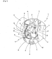
- FIG. 1 in a perspective schematic view shows a longitudinal cross-section of an embodiment of a centre portion of a rotor 41 of a wind turbine generator 40, comprising a hub 30 mounted to a generator shaft 31 of the wind turbine generator 40, seen in a first viewing direction.
- the generator shaft 31 is formed as a sleeve shaft; however, various other forms are possible as well.
- the hub 30 is rotatable around a rotation axis that is identical with a rotation axis of the generator shaft 31, the rotation axis being longitudinally located in the centre of the generator shaft 31.
- the wind turbine generator 40 and its construction parts as far as they are of importance in context with the described embodiments of the present invention will be discussed hereinafter in more detail in context with Figure 1 and the further Figures of the drawings.
- a number of rotor blades being arranged radially around the rotation axis are mounted to the hub 30.
- three rotor blades are provided, of which rotor blades in the presentation of Figure 1 only a first one and a second one, denoted by reference numerals 32 and 33, respectively, are partly visible.
- a third rotor blade 34 has been cut away in the view shown in Figure 1 .
- a part of the third rotor blade 34 is, however, shown in Figure 15 described below.
- the hub 30 is at least mainly surrounded by a spinner 35.
- the spinner covers all portions of the hub except those portions where the rotor blades 32, 33 and 34 are mounted to the hub 30, and except a rear portion of the hub 30 in the ambience of the generator shaft 31, where the spinner adjoins a nacelle 50, that is a portion of the hub 30 that is faced to the nacelle 50, as is shown in and will be described in context with Figures 2 and 3 , thus providing a weather protection for the hub 30 and all construction parts mounted to the hub 30.
- the hub 30 in the embodiment shown in Figure 1 is provided with a front opening 36 at least mainly centrically arranged with respect to the rotation axis.
- the front opening 36 serves as an intake for an air stream used for cooling of the wind turbine generator 40, especially for cooling a generator arrangement comprised in the wind turbine generator 40.
- the front opening 36 is further connected to an air duct 37 extending along the rotation axis of the hub 30 to a front portion of the spinner 35, at which front portion the air duct 37 further is connected to a front opening 38 of the spinner 35. From this front opening 38 of the spinner 35, air can flow through the air duct 37 and the front opening 36 of the hub 30 into the interior of the hub 30.
- the air duct 37 further comprises a filter-ventilator unit 39 controlling the air flow and filtering dirt and moisture from the air flowing in.
- the embodiment of the rotor 41 of the wind turbine generator 40 shown in Figure 1 further comprises a track system 100.
- the embodiment of this track system 100 as shown in the Figures of the accompanying drawings consists of a number of tracks 101, 102 and 103, respectively, which tracks 101, 102, 103 are installed on an outside of the hub.
- Each of the tracks 101, 102, 103 leads from a front portion of the hub 30 along its surface between two neighbouring ones of the rotor blades 32, 33, and 34, respectively, to the rear portion of the hub 30faced to the nacelle 50.
- a first one of the tracks leads from the front portion of the hub 30, that is from an edge of the front opening 36 of the hub 30, between the first and the third neighbouring rotor blades 32, 34 to the rear portion of the hub 30 faced to the nacelle 50.
- a second one of the tracks leads from the edge of the front opening 36 of the hub 30 between the first and the second neighbouring rotor blades 32, 33 to the rear portion of the hub 30, and the third one of the tracks, denoted by reference numeral 103 and shown in Figures 3 and 4 described below in more detail, leads from the edge of the front opening 36 of the hub 30 between the second and the third neighbouring rotor blades 33, 34 to the rear portion of the hub 30.
- the track system further comprises a first extension track 104 which is installed in the nacelle 50. According to the current position in which the rotor 41 is stopped, the first extension track 104 is connectable to one of each of the first, second and third track 101, 102, 103, respectively.
- the first extension track 104 is removably mounted in the nacelle 50, so that it is mounted in case a transport by means of the track system 100 has to be performed, for instance in case of maintenance or the like of the wind turbine generator 40, and is detached afterwards before starting operation of the wind turbine generator 40.
- the tracks 101, 102, 103, respectively, and the first extension track 104 are arranged to be connectable in the region of a manhole (not shown in the Figures) disposed in a front side 51 of a housing 52 of the nacelle 50.
- the first, second or third track 101, 102, 103, respectively, on the one hand, and the first extension track 104 on the other hand thus form a common track extending through this manhole.
- a passage is formed from the housing 52 of the nacelle 50 to the outside of the hub 50 and from there advantageously to the inside of the spinner 35 surrounding the hub 30 and forming a housing for the hub 30.
- a weather protected transport path is provided by the track system from the front opening 36 of the hub 30 to the interior of the housing 52 of the nacelle 50.
- the embodiment of the track system 100 further comprises three second extension tracks.
- the second extension tracks are movably arranged at the front portion of the hub 30, especially at the edge of the front opening 36 of the hub 30.
- Each one of the second extension tracks is adapted to be connected to one of the first, second and third track 101, 102, 103, respectively, at the front portion of the hub 30, that is at the edge of the front opening 36.
- second extension track "one" 105 is to be connected to the first track 101 of the track system 100.
- second extension track "two" (not visible in the Figures) is to be connected to the second track 102 of the track system 100
- second extension track "three" 107 is to be connected to the third track 103 of the track system 100.
- the second extension tracks 105, 107 are formed as hinged tracks, that is the second extension tracks 105, 107 have hinges to fasten the second extension tracks 105, 107 (and, of course, also second extension track "two" though not shown in the Figures) to the edge of the front opening 36 at the front portion of the hub 30.
- the second extension tracks are pivotably arranged in the region of the front opening 36 of the hub and thus can be pivoted so as to be located directly in the front opening 36 or in front of the front opening 36. In this position, each one of the second extension tracks is connected to the respective track 101, 102, 103 of the track system 100 on the outside of the hub 30.
- second extension track “one” and second extension track “three” are shown in their respective parking positions.
- the tracks 101, 102, 103 of the track system 100 as well as the second extension tracks may be detachably mounted to the hub 30. Accordingly, in order to facilitate mounting and detaching of the track system 100, the tracks 101, 102, 103 and the second extension tracks may have a magnetic attachment to the hub 30. In the same manner, the first extension track 104 may have a magnetic attachment to the nacelle 50.
- the tracks 101, 102, 103 of the track system 100 as well as the second extension tracks may be permanently mounted to the hub 30. Accordingly, in order to provide for simple and rigid mounting means for the track system 100 to be fastened, the tracks 101, 102, 103 and the second extension tracks may have a bolted attachment to the hub 30. Moreover, the first extension track 104 may as well have a bolted attachment to the nacelle 50.
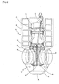
- FIG 2 an embodiment of the wind turbine generator 40 to which the track system 100 according to the embodiment of the present invention as described beforehand is installed is partly shown in a top view, seen in a second viewing direction along the section plane of said longitudinal cross-section shown in Figure 1 .
- Elements in Figure 2 and in the following Figures that are identical with those elements already described in the foregoing are denoted by identical reference numerals.
- the embodiment of the wind turbine generator 40 according to Figure 2 comprises the embodiment of the rotor 41, the centre portion of which rotor 41 is described beforehand in context with Figure 1 .
- the rotor 41 is combined with the embodiment of the nacelle 50 mentioned above, which nacelle 50 especially is installed on a tip end part of a tower (not shown).
- the generator shaft 31 is supported in the nacelle 50, so that the rear portion of the hub 30 in the ambience of the generator shaft 31 adjoins the nacelle 50, especially the front side 51 of the housing 52 of the nacelle 50.
- the nacelle 50 Surrounded by this housing 52, the nacelle 50 includes machinery 42 for generating and providing electrical energy by means of a wind-driven rotation of the rotor 41 and thus of the generator shaft 31. As this machinery 42 does not directly impact on the present invention, a more detailed description of these parts of the wind turbine generator is omitted here.
- a crane 43 is installed for lifting loads, for instance spare parts, tools and the like, preferably for the purpose of mounting, repair and maintenance of the wind turbine generator 40, within the housing 52 of the nacelle 50.
- the crane 43 may be used for handling loads outside the housing 52 of the nacelle 50 as well, in case there are one or more openings, such as hatches or the like, provided in the housing 52 for enabling the beam of the crane to project to the outside of the nacelle 50.
- the crane 43 is provided with a telescopic beam; however, other constructions are possible as well, for instance a crane with an articulated arm or a knuckle crane or a rail-element with means for lifting and/or transporting a load as shown in EP 2 363 598 A1 .
- the crane 43 may be a portable crane that is detachably mounted to the nacelle so that it can be removed in case it is not needed in the wind turbine generator, especially during operation of the wind turbine generator. A particular use of the crane 43 in context with embodiments of the present invention will be described hereinafter.
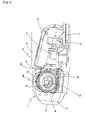
- Figure 3 a side view of the wind turbine generator 40 shown in Figure 2 is shown, seen in a third viewing direction perpendicular to the section plane of the longitudinal cross-section of Figure 1 , i.e. perpendicular to said second viewing direction as mentioned above.
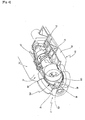
- Figure 4 further shows a perspective view of the wind turbine generator 40 of Figures 2 and 3 , seen in a fourth viewing direction relative to said section plane of said longitudinal cross-section.
- the track system 100 further comprises a wagon 110 which is adapted to run on the tracks 101, 102, 103, on the first extension track 104, on second extension track "one” 105, on second extension track “two” and on second extension track “three” 107, respectively, and is to be used for transporting a load, especially for component transportation.
- a wagon 110 which is adapted to run on the tracks 101, 102, 103, on the first extension track 104, on second extension track "one” 105, on second extension track “two” and on second extension track “three” 107, respectively, and is to be used for transporting a load, especially for component transportation.
- FIG. 5 An embodiment of a wagon 110 of this kind is schematically shown in Fig. 5 .
- the wagon 110 is built as a platform wagon with rollers 111 attached to it, the wagon 110 moving along said tracks by means of the rollers 111.
- the wagon 110 can run on all other tracks described beforehand as well.
- the wagon 110 is provided with a hinged plate (not shown) to prevent the load from slipping. Further, the wagon 110 is provided with means for sufficiently securing the load in form of especially tension belts or the like (not shown).
- the tracks comprised by the track system 100 generally comprise one or more rails.
- the first track 101 of the embodiment of the track system 100 as shown advantageously is formed from four rails 112, 113, 114, 115, that is two pairs of rails, the pairs denoted by the reference numerals 112, 113 and 114, 115, respectively.
- the two rails 112, 113 of a first one of the pairs are arranged in a fixed distance to each other.
- the two rails 114, 115 of a second one of the pairs are arranged in a fixed distance to each other as well.
- all other tracks of the embodiment of the track system 100 as shown that is the second and third track 102, 103, the first extension track 104 and the second extension tracks 105, 107, comprise two pairs of rails arranged in said fixed distance to each other as well.
- the rollers 111 of the wagon 110 in this configuration of rails are guided between the two rails of each of the pairs 112, 113 and 114, 115.
- the pairs of rails 112, 113, 114, 115 together with the rollers 111 placed between the two pairs of rails thus form a first embodiment of a derailment guard arrangement.
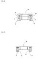
- FIG. 6 a schematic front view of a second embodiment of a wagon 110 adapted for a second embodiment of a track system 100, in combination with a second embodiment of a derailment guard arrangement is shown.
- the tracks 101 to 107 are formed from two rails 116, 117 each.
- the wagon 110 in this embodiment is provided with two pairs of rollers 118, 119 and 120, 121, respectively, wherein the rollers 118, 119 and 120, 121, respectively, of each of the pairs of rollers are arranged in a fixed distance to each other, and wherein one of the rails 116, 117 of the tracks 101 to 107 is disposed between the rollers 118, 119 and 120, 121, respectively, of the roller pairs.
- the derailment guard arrangement in this embodiment comprises two pairs of rollers arranged around two rails.
- Figure 7 shows a schematic front view of a third embodiment of a wagon 110 adapted for a third embodiment of a track system 100, in combination with a third embodiment of a derailment guard arrangement.
- the tracks 101 to 107 are formed from two U-sections 123 arranged adjacently and at least mainly in parallel, the openings of the U-sections 123 turned to each other. In these U-sections, rollers 122 mounted to the wagon 110 are guided. Thus, a derailment of the wagon from the tracks 101 to 107 is avoided.
- a wagon moving means 124 adapted for moving the wagon 110 along the first, second or third track 101, 102, 103 or along the first extension track 104 or along the second extension tracks 105, 107 is schematically shown.
- the wagon moving means 124 comprises electrical or mechanical or manual hoisting means, preferably a winch or hoist 125.
- the winch or hoist 125 is provided with a rope-like element 126, especially a rope, a chain, or the like.
- the winch or hoist moves, that is: pulls, the wagon 110 by means of the rope-like element 126.
- the wagon 110 at its front end 127 is provided with a connector device 128 by which the rope-like element 126 of the winch or hoist 125 is fixed to the front end 127 of the wagon 110.
- the winch or hoist 125 of said wagon moving means 124 is disposed inside the nacelle 50.
- the wagon thus can be simply moved by one single moving means 124, that is by one single winch or hoist 125 and by one single rope-like element 126, along each one of the tracks 101 to 107 of the track system 100.
- the track system 100 further comprises a rope-like safety element 129 which is fixed to the wagon 110, wherein the rope-like safety element 129 is adapted to control the movement of the wagon.
- the wagon 110 at its rear end 130 is provided with a second connector device 131 by which the rope-like safety element 129 is fixed to the rear end 130 of the wagon 110.
- the rope-like safety element 129 is especially provided in form of a rope, a chain, or the like.
- the rope-like element 126 and the rope-like safety element 129 are pulled in opposite moving directions of the wagon 110, the pulling force of that one of the elements 126, 129, respectively, that pulls the wagon 110 in the chosen direction being an appropriate amount larger than the pulling force of the other one of said elements 126, 129, respectively.
- the spinner 35 on its inside provides a tunnel-like shaped space along the first, second and third track 101, 102 and 103, respectively, of the track system 100 for enabling the wagon 110 to perform component transportation along the tracks 101, 102, 103.
- the tunnel-like shaped space forms passageway for the wagon 110 and the load fixed to the wagon 110 along the outside of the hub 30 and inside the spinner 35.
- the manhole is disposed in the front side 51 of the housing 52 of the nacelle 50 such that the aforementioned passageway is formed from the housing 52 of the nacelle 50 to the inside of the spinner 35 surrounding the hub 30 and forming a housing for the hub 30 preferably passing said manhole.
- the spinner 35 is provided with a bulge above each one of the first, second and third track 101, 102, 103 of the track system 100 for allowing the wagon 110 and the load to pass along said tracks 101, 102, 103.
- the tunnel-like shaped space beneath the bulges, and thus the bulges themselves are formed such that the load with the largest dimensions expected to be transported can pass along said tracks 101, 102, 103 without difficulties.
- one of the bulges denoted by reference numeral 140 is shown arranged beneath the first track 101. Similar bulges are arranged beneath the second and third tracks 102, 103 as well.
- At least one portion of the spinner material including the bulge 140 above the first track 101 is formed as a separate construction part that is mountable and detachable from the remaining portions of the spinner 35 aside the first track 101, so that an additional possibility is provided for accessing the first track 101 from outside the spinner 35 or for enhancing the possibility of transporting extremely bulky loads along he first track 101.
- a similar arrangement is provided for the bulges beneath the second and third track 102, 103 as well.
- the crane 43 is particularly adapted for lifting the wagon 110 or the load to be transported by the wagon 110 in the nacelle 50.
- the wagon 110 is moved to the first extension track 104.
- the wagon 110 and/or the load are lifted from this position by the crane 43 and can be transported inside or outside the housing 52 of the nacelle 50, in case there are one or more openings, such as hatches or the like, provided in the housing 52 for enabling the beam of the crane to project to the outside of the nacelle 50, as described beforehand.
- the position into which the crane 43 is brought for lifting the wagon 110 and/or the load from the first extension track 104 is shown in Figures 2 , 3 and 4 .
- the embodiment according to Figure 1 further shows a pivot crane 150 located in the interior of the hub 30.
- the pivot crane 150 mainly comprises a crane beam 151 movably coupled at one of its ends by a pivot, especially a ball joint 152, to a supporting frame 153.
- the supporting frame 153 is fixedly attached to the generator shaft 31 and is rotatable together with the generator shaft 31.
- the crane beam 151 is provided with means for hoisting a load.
- the pivot crane 150 is shown in a parking position taken during operation of the wind turbine generator 40.
- the pivot crane 150 is adapted to handle and transport the load inside the hub 30, preferably to hoist the load onto or from the wagon 110.
- pitch drive motors 60, 61 for the first and second rotor blade 32, 33, respectively, are shown.
- a third pitch drive motor (not shown) is provided in the hub 30 for the third rotor blade 34 as well.
- These pitch drive motors are provided for adjusting the pitch of the rotor blades 32, 33, 34, respectively, according to the operation conditions of the wind turbine generator 40, for instance the wind force and the amount of electrical power to be delivered by the wind turbine generator 40.
- these pitch drive motors 60, 61 are preferably detached from the hub 30 and transported to the nacelle 50.
- FIGs 8 to 16 show a sequence of nine steps of a transport process as an embodiment and example for a method.
- the rotor 41 of the wind turbine generator 40 is locked in a position in which the hub 30 is arranged in a blade Y-shape position; that is, in the arrangement shown in Figures 1 and 8 , the first and the third rotor blade 32, 34 point upwards under an angle of 30° with respect to the horizon each, whereas the second rotor blade points straight downward.
- the portion of the hub 30 carrying the first track 101 is allocated straight beneath the rotation axis of the rotor 41, that is the rotation axis of the hub 30 and the generator shaft 31.
- the first track 101 is allocated at the top of the hub 30 and is therefore used for transportation of a load, for instance of components, spare parts, tools and the like needed for maintenance of the wind turbine generator 40.
- the example of the transport process described hereinafter especially shows a transport action carried out for the purpose of pitch drive motor replacement.
- Figure 8 shows the embodiment of the centre portion of the rotor 41 of Figure 1 in the state of a first step of the embodiment of the transportation method.
- the second extension track "one”, denoted by reference numeral 105 and named “second extension track 105" hereinafter for the sake of simplicity is moved from its parking position as shown in Figure 1 and allocated just in front of the front opening 36 of the hub 30, where it is connected to the first track 101 so as to form a continuous transport path for the wagon 110.
- the first track 101 is also connectable to the first extension track 104, which connection is established for the described first step of the transportation method.
- the wagon 110 is set onto the first extension track 104 in the nacelle 50 and is moved by means of the described wagon moving means 124 along the first extension track 104 and the first track 101 until it arrives on the second extension track 105.
- This stage of the transportation method is shown in Figure 8 .
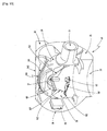
- FIG 9 shows the embodiment of the centre portion of the rotor 41 of Figure 1 in the state of a second step of the embodiment of the transportation method.
- the second extension track 105 together with the wagon 110 allocated thereon is pivoted into an at least nearly horizontal position. This is performed by swivelling the second extension track 105 together with the wagon 110 allocated thereon around the hinges by which the second extension track 105 is connected to the hub 30.
- the wagon 110 is locked to the second extension track 105 by braking means (not shown).
- the rope-like element 126 of the wagon moving means 124 is detached from the front end 127 of the wagon 110 by appropriately actuating the connector device 128 by which the rope-like element 126 of the winch or hoist 125 is fixed to the front end 127 of the wagon 110.
- Figure 9 shows that in said second step of the embodiment of the transportation method shown the pivot crane 150 is unlocked from its parking position and is pivoted into a position in which its crane beam 151 is arranged at least mainly vertically beneath the pitch drive motor 61 for the second rotor blade 33, which pitch drive motor 61 in the embodiment shown is deemed to be detached from the hub and transported to the nacelle 50 for maintenance purposes.
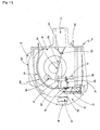
- FIG 10 shows the embodiment of the centre portion of the rotor 41 of Figure 1 in the state of a third step of the embodiment of the transportation method.
- the pitch drive motor 61 is attached to the crane beam 151 of the pivot crane 150 by means of a hook, a hoist or the like (not shown), and is secured by the pivot crane.
- the pitch drive motor 61 is detached from a socket 62 which, for instance, is adapted for mounting the pitch drive motor 61 to the hub 30 and may also contain a gear or the like for transmitting a pitch adjusting movement from the pitch drive motor 61 to the second rotor blade 33.
- the pitch drive motor 61 is lifted off the socket 62, which action is shown in Figure 10 .
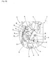
- FIG 11 shows the embodiment of the centre portion of the rotor 41 of Figure 1 in the state of a fourth step of the embodiment of the transportation method.
- the crane beam 151 of the pivot crane 150 is pivoted beneath the wagon 110 on the second extension track 105 and the pitch drive motor 61 is lowered onto the wagon 110.
- FIG 12 shows the embodiment of the centre portion of the rotor 41 of Figure 1 in the state of a fifth step of the embodiment of the transportation method.
- the pitch drive motor 61 is turned into a horizontal position for being further fixed and transported on the wagon 110 more safely.
- the pitch drive motor 61 thus forming the load to be transported by the wagon 110 is then appropriately and sufficiently secured on the wagon 110, for instance by means of tension belts or the like (not shown) as described beforehand.
- the second extension track 105 on which the wagon 110 runs is used for transportation of the load inside the hub 30, wherein the load preferably is a component or spare part for the hub30, that is the pitch drive motor 61 in the embodiment shown.
- FIG 13 shows the embodiment of the centre portion of the rotor 41 of Figure 1 in the state of a sixth step of the embodiment of the transportation method, in this sixth step, the pitch drive motor 61 is detached from the pivot crane 150. Then, the second extension track 105 together with the wagon 110 allocated thereon and the pitch drive motor 61 allocated on the wagon 110 and fixed thereon is pivoted back into the at least nearly vertical position in which the second extension track 105 is again connected to the first track 101. This is performed by swivelling the second extension track 105 together with the wagon 110 allocated thereon and the pitch drive motor 61 allocated on the wagon 110 around the hinges by which the second extension track 105 is connected to the hub 30.
- the wagon 110 is still locked to the second extension track 105 by the braking means (not shown) as mentioned above. Then, if having been detached in the second step of the embodiment of the transportation method as described beforehand in context with Figure 9 , the rope-like element 126 of the wagon moving means 124 again is attached to the front end 127 of the wagon 110 by appropriately actuating the connector device 128, thus again fixing the rope-like element 126 of the winch or hoist 125 to the front end 127 of the wagon 110.
- the rope-like safety element 129 preferably can remain attached to the rear end 130 of the wagon 110.
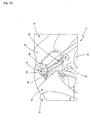
- Figure 14 shows the embodiment of the centre portion of the rotor 41 of Figure 1 in the state of a seventh step of the embodiment of the transportation method.
- the wagon together with the pitch drive motor 61 is pulled along the transport path formed by the second extension track 105, the first track 101 and the first extension track 104, by means of the wagon moving means 124.
- Figure 14 shows the wagon 110 in a position in which it has just left the second extension track 105 and is still moved along the first track 101 in the ambience of the front opening 36 of the hub 30.
- Figure 15 shows the embodiment of the centre portion of the rotor 41 of Figure 1 in the state of an eighth step of the embodiment of the transportation method.
- the wagon 110 is further moved along the first track 101 and has reached a position directly between the first rotor blade 32 and the third rotor blade 34, that is at a vertex of the curvature of the hub 30.
- Figure 16 shows the embodiment of the centre portion of the rotor 41 of Figure 1 in the state of a ninth step of the embodiment of the transportation method.
- the wagon 110 with the pitch drive motor 61 fixed thereon is moved just to that end of the first track 101 where it is connected to the first extension track 104. From this position, the wagon 110 can be moved onto the first extension track 104, where the pitch drive motor 61 can be lifted off the wagon 110 for further transport.
- the track system 100 is used to carry spare parts and tools inside the rotor head, that is especially the hub 30, and used components into the nacelle 50 for transportation by the crane 43 in the nacelle 50.
- the track system 100 comprises a fixed part mounted on the surface, that is the outside of the hub 30 and a second extension rail 105 formed as a hinged part of the track that reaches inside the hub 30 to be loaded with the components.
- a wagon 110 is installed to transport the components.
- the second extension track 105 being formed as the hinged part or in another variation additionally to the second extension track 105 it is also possible to have the pivot crane 150 inside the hub 30 extendible so as to bring the components outside the hub 30, where the components can be fixed on the wagon 110 directly.
- Either the wagon 110 or the tracks are designed in a way to provide for a derailment guard arrangement.
Description
- The disclosure relates to a track system for a wind turbine generator.
- From
EP 2 363 598 A1 a wind turbine is known comprising a nacelle being rotatably disposed on a tower with the nacelle having a first cavity, a generator housing portion disposed upstream to the nacelle having a second cavity, a hub disposed upstream to the generator housing portion with attached rotor blades at it having a third cavity, whereby the first, second and third cavities communicate with one another. A rail system is provided that extends through all cavities and comprises three rail-elements. The rail system further has a means for lifting and/or transporting components, especially construction components of the wind turbine in case of maintenance. The means for lifting and/or transporting are movable along the rail-system. Such, the components can be moved from the nacelle through the generator housing portion to the hub. The three rail-elements further give rise to an enhancement of length of the rail-system. A rear end of a first one of the rail elements disposed within the nacelle is even extendible to the outside of the wind turbine through a first opening that can be closed by a hatch. - An alternate loading opening may be disposed at a free ending of the hub as well. The rail system thus can be prolonged from outside one ending of the upper part of the wind turbine through the hub, the generator housing portion and the nacelle to the opposite ending of the wind turbine.
- The extension of the length of the rail-system is achieved by a telescopic mechanism letting the first one of the rail elements slide from a rest position within a second one of the rail-elements towards the rear end of the nacelle and further outside the nacelle until it reaches its final prolonged state. The extension of the length of the rail-system into the hub is achieved by mounting a third one of the rail-elements to the second one of the rail-elements building a stable and secure connection by means of screws or welding.
- Additionally, a crane and hoist system is disposed on the outer surface of the nacelle and the generator housing portion being connectable to the rail-system. The crane and hoist system may communicate with the means for lifting and/or transporting over a third loading opening thereby enhancing the degrees of freedom such as the directions of movement of a hoisted or lifted component. The crane and hoist system may be detachably attached to a second rail-system allowing axial movements of the crane and hoist system on the outer surface of the wind turbine, i.e. the nacelle and the generator housing portion, so that it is possible to attach the crane and hoist system only in cases of maintenance of the wind turbine. The third loading opening is closable by a pivotably movable hatch as well.
- According to a further variation described in
EP 2 363 598 A1 , the means for lifting and/or transporting is collapsible. Consequently, the means for lifting and/or transporting is in its collapsed state during operation of the wind turbine and in its non-collapsed state during maintenance works or the like. - In the wind turbine known from
EP 2 363 598 A1 , a direct passage from the nacelle via the generator housing to the interior of the hub is presupposed. However, in some constructions of wind turbines, this cannot be provided. - It is an object of some embodiments of the present invention to design a track system for a wind turbine generator that avoids the above-mentioned problems and provides a more flexible transporting means, especially in cases where no direct access from the nacelle to the interior of the hub is possible.
- This object is achieved by a track system for a wind turbine generator, the wind turbine generator comprising:
- a nacelle, especially a nacelle which is installed on a tip end part of a tower,
- a hub rotatable around a rotation axis and connected to a number of rotor blades being arranged radially around the rotation axis,
- wherein the track system comprises at least one track which is installed on the outside of the hub leading from a front portion of the hub between two neighbouring rotor blades to a rear portion of the hub, said rear portion facing the nacelle, and
- the track system further comprising a wagon which is adapted to run on the at least one track, said wagon being adapted for component transportation.
- In this context, the at least one track may be any kind of guidance means that is adapted for guiding a wagon along a predetermined path. The wagon has to be understood as being any kind of means adapted for transporting a load at least along the at least one track of the track system. A load of the mentioned kind is understood to be any goods to be transported in the ambience of the wind turbine generator, especially in the ambience of the hub, and especially for the purpose of mounting, repair or maintenance of the wind turbine generator and its construction parts. Preferably, such a load can be spare parts and tools for mounting, repair and maintenance as well as used components to be dismounted and removed from the wind turbine generator or its subassemblies. Wind turbine generators are also commonly referred to as wind turbines or wind energy converters.
- The track system according to some embodiments of the invention allows for a load, especially a heavy load, to be easily and safely transported from the nacelle or its ambience to the front portion of the hub, from where preferably the interior of the hub may be entered in a simple manner. Thus, a transport of that kind is easily and safely performed even in case there is no direct access from the nacelle to the interior of the hub. This enhances the constructive freedom for building the wind turbine generator without any restrictions during its operation.
- According to embodiments of the invention, the at least one track of the track system comprises one or more rails. In this context, the one or more rails have to be understood as any kind of guidance members, preferably elongated along the prede-termined path along which the wagon has to be moved and guided. Especially, the one or more rails can be formed in a conventional manner; they can have cross-sections of various shapes and can be made from various materials, such as steel, aluminium, alloys or mixtures of these or other metals, but also from plastics, such as glass-fibre reinforced plastics, or the like. Further, there can be various numbers of rails forming the at least one track. Most preferably, the at least one track is formed from two or four rails, as will be explained in more detail hereinafter.
- In a further embodiment, the track system further comprises a first extension track which is connectable to the at least one track and is installed in the nacelle. By this means, the transport path provided by the track system can easily and simply be extended into the nacelle in case of mounting, repair or maintenance, to allow for a load, e.g. construction parts or the like, to be easily and safely transported from and into the interior of the nacelle, respectively, where this load can easily and thus more advantageously be handled for further transport, repair, maintenance, or the like. However, for enabling operation of the wind turbine generator without any restrictions, the connection of the first extension track to the at least one track on an outside of the hub will be installed only during maintenance works or the like.
- Preferably, in the embodiment of the track system described beforehand, the at least one track and the first extension track are connectable in the region of a manhole disposed in the front side of a housing of the nacelle so as to form a common track extending through the manhole. In this manner, the manhole is adapted for not only providing a passage for personnel in case of mounting, repair or maintenance of the wind turbine generator, but is used for transport of spare parts, tools and the like as well. The manhole is disposed in the housing of the nacelle especially such that a passage is formed from the housing of the nacelle to the outside of the hub.
- In some embodiments, the track system further comprises at least one second extension track being movably arranged at the front portion of the hub and being adapted to connect to the at least one track at the front portion of the hub. The at least one second extension track allows for a safe and simple transport of a load by means of the wagon in the ambience of the front portion of the hub. In combination with the first extension track such a transport can easily be performed from the nacelle to the front portion of the hub and vice versa. This is especially preferable in view of a hub having an opening at its front portion, especially an opening for ventilation purposes, which according to embodiments of the invention is used additionally for the purpose of transportation of a load between the nacelle and the interior of the hub via said front opening.
- To this purpose, in the track system according a further embodiment of the present invention, the at least one second extension track is formed as a hinged track which has hinges to connect the at least one second extension track to the front portion of the hub. This allows for a simple connection of the at least one second extension track to the at least one track of the track system, which connection is easily mountable and detachable with respect to the fact that the at least one second extension track preferably is removed from the front opening of the hub in order not to restrict the use of the front opening for e.g. ventilation purposes during operation of the wind turbine generator.
- Preferably, the at least one second extension track is installed in the region of a front opening of the hub. This especially means that the at least one second extension track is installed in the front opening or in the vicinity of the front opening of the hub.
- According to another embodiment of the track system, the at least one track or the at least one second extension track has a magnetic attachment to the hub, or the first extension track has a magnetic attachment to the nacelle. In a variation, the at least one track or the at least one second extension track has a bolted attachment to the hub, or the first extension track has a bolted attachment to the nacelle. By this means, different possibilities are provided for a rigid and simple attachment that allows for easy handling during installation and operation. Especially a magnetic attachment allows for a quick mounting and removal of the components of the track system, so that the track system can be easily mounted to the wind turbine generator in case it is needed for mounting, repair or maintenance purposes and can be removed after such work is finished, because in many cases there is no need to permanently provide the track system on the wind turbine generator. This allows for cost and weight savings.
- In another embodiment, the track system comprises a derailment guard arrangement for avoiding the derailment of the wagon from the track. Especially where (according to the form of the hub) the track does not take a horizontal course, this allows for a safe movement of the wagon along the track.
- Further, the derailment guard arrangement comprises at least one pair of rollers, wherein the rollers are arranged in a fixed distance to each other, and wherein a rail of the at least one track is disposed between the rollers of the at least one roller pair. Thus, the rollers of each of the at least one roller pair encompass the respective rail and in this manner hold the wagon on the at least one track of the track system. Of course, a similar arrangement may also be provided for the first extension track or the at least one second extension track, respectively, as well.
- Most preferably, In case of a derailment guard arrangement according to the beforementioned embodiment, the at least one track, and the first extension track and the at least one second extension track as well, are formed from two rails, thus forming a simple arrangement.
- In the track system according to embodiments of the invention, the at least one track or the first extension track or the at least one second extension track comprise at least two rails arranged in a fixed distance to each other, and the derailment guard arrangement comprises rollers placed between the at least two rails. In this embodiment, the at least two rails arranged in a fixed distance to each other encompass each of said rollers. This allows for a simpler construction of the wagon.
- In case the derailment guard arrangement is formed with the at least two rails arranged in a fixed distance to each other, the at least one track is formed from four rails. However, in a variation of this embodiment, instead of two rails arranged in a fixed distance to each other, especially two separated rails arranged in a fixed distance to each other, a single rail can be provided especially formed with a cross-section having two portions, preferably end portions, encompassing said rollers; the cross-section further having a middle portion connecting said end portions. Such a rail may be formed in the manner of a U-shaped beam, for example.
- According to another embodiment the track system further comprises wagon moving means adapted for moving the wagon along the at least one track or the first extension track or the at least one second extension track. These wagon moving means allow for safely, easily and precisely moving the wagon even in case a heavy load is to be transported.
- Further preferably, the wagon moving means comprise electrical or mechanical or manual hoisting means, preferably a winch or hoist, and said wagon moving means being disposed inside the nacelle. Further, a rope-like element fixed to the wagon for moving the wagon along the at least one track or along the first extension track or along the at least one second extension track is provided, wherein the wagon is to be pulled by the hoisting means. This allows for a particularly simple and light-weight construction that is flexible in use and can be handled easily. The rope-like element may, for example, be a rope, a chain, a cable, a wire, a belt or a cord.
- In order to even more safely and comfortably handle the wagon along the tracks, in another embodiment the track system further comprises a rope-like safety element which is fixed to the wagon, wherein the rope-like safety element is adapted to control the movement of the wagon. The rope-like safety element may, for example, comprise a rope, a chain, a cable, a wire, a belt or a cord.
- According to another embodiment the track system further comprises a crane for lifting the wagon or a load to be transported by the wagon in the nacelle. This crane preferably is mounted to the nacelle and is adapted to be used within the housing of the nacelle, but may be also used for transportation purposes outside the nacelle, especially by means of loading openings or the like, provided in the housing of the nacelle. Thus, a simple, universal and efficient means for further transport of the load and/or the wagon, respectively, is provided.
- The above-mentioned objects are further achieved by a wind turbine generator, comprising
- a nacelle, especially a nacelle which is installed on a tip end part of a tower,
- a hub rotatable around a rotation axis and connected to a number of rotor blades being arranged radially around the rotation axis,
- the wind turbine generator further comprising a track system having at least one track which is installed on the outside of the hub leading from a front portion of the hub between two neighbouring rotor blades to a rear portion of the hub, said rear portion facing the nacelle, and
- the track system further comprising a wagon which is adapted to run on the at least one track and is to be used for component transportation.
- In a further embodiment, a wind turbine generator of the pre-described kind further comprises a spinner at least mainly surrounding the hub, the spinner on its inside providing a tunnel-like shaped space at least along the at least one track of the track system for enabling the wagon to perform component transportation along the at least one track.
- This tunnel-like shaped space forms a passage or passageway for the wagon, said tunnel-like shaped space being bound by the outer side of the hub and the inner side of the spinner. The load is transported by the wagon in said tunnel-like shaped space and along the outer side of the hub. Preferably, the spinner surrounding the hub and forming a housing for the hub is provided with one or more appropriate bulges or the like above the at least one track of the track system for allowing the wagon and the load to pass along the at least one track. The tunnel-like shaped space, i.e. the space beneath the one or more bulges, and thus the one or more bulges themselves are formed such that the one of the loads to be transported having the largest dimensions can pass along the at least one track unimpeded. This construction allows for an efficient protection of the track system, the load to be transported and the personnel handling the track system against atmospheric influence. This is especially important in case the wind turbine generator in concern is installed offshore.
- Preferably, at least one portion of the spinner material including the one or more bulges above the at least one track of the track system is formed as a separate construction part that is mountable and detachable from the remaining portions of the spinner aside the at least one track of the track system, so that an additional possibility is provided for accessing the at least one track of the track system from outside the spinner or for enhancing the possibility of transporting extremely bulky loads.
- With respect to the embodiment described beforehand, the above-mentioned manhole providing a passage between the nacelle and the outside of the hub is disposed in the housing of the nacelle such that said passage is formed from the housing of the nacelle preferably to the inside of the spinner.
- The above-mentioned objects are further achieved by a method for use of a track system of the pre-described kind, wherein under the condition that the hub is arranged in a blade Y-shape position and that more than one track are provided, the topmost track of the hub is used for transportation of components. A blade Y-shape position especially is achieved in case there are three rotor blades mounted to the hub, preferably offset by 120° each, when one of the blades directly points downward and the portion of the hub located between the other two rotor blades directly points upward. In more general terms, a blade Y-shape position is achieved when a portion of the hub located between any two neighbouring rotor blades directly points upward.
- There are various possibilities for arranging the track system according to embodiments of the invention and thus carrying out the method mentioned beforehand. In a cost-efficient and simple version, the track system only comprises one single track which is installed on the outer side of the hub leading from the front portion of the hub along only one of the gaps or spacings between each of two neighbouring rotor blades to the rear portion of the hub faced to the nacelle, whereas there is no track provided along the other gaps or spacings. However, this only allows for using the track system in case of only one well-defined rotor position, whereas in some cases of mounting, repair or maintenance of the wind turbine generator, for example in case of mounting, replacement, repair or maintenance of a pitch drive motor for one or more of the blades, the necessity may occur to stop the rotor in another position, especially in another one of the possible blade Y-shaped positions. This is facilitated by providing a track along more than one, preferably along each of the gaps or spacings between each of two neighbouring rotor blades.
- In a further embodiment of the method for use of the track system described beforehand, the at least one second extension track on which the wagon runs is used for transportation of a load, preferably a component or spare part for the hub, inside the hub. Thus, a uniform transport path for the load from the nacelle to the inside of the hub is provided, enabling a simple and easy transport operation.
- In summary, the advantage of the track system as described is that there is no need to use the crane in the nacelle for handling of components inside the hub or the spinner. This allows keeping the spinner and the nacelle closed and does not expose the inside of the spinner and that of the nacelle to the outside environment. The components are at all times secured and there is a reduced probability that components can fall and thereby cause severe destructions.
- Embodiments of the invention will be described below with reference to the following figures which show in schematic representation:
- [
fig.1]Figure 1 is a perspective view of a longitudinal cross-section of an embodiment of a centre portion of a rotor of a wind turbine generator, seen in a first viewing direction; the wind turbine generator including a hub, rotor blades mounted to the hub, and an embodiment of a track system; - [
fig.2]Figure 2 is a top view of a wind turbine generator comprising said embodiment of the centre portion of the rotor ofFigure 1 in combination with an embodiment of a nacelle, seen in a second viewing direction along the section plane of said longitudinal cross-section shown inFigure 1 ; - [
fig.3]Figure 3 is a side view of the wind turbine generator shown inFigure 2 , seen in a third viewing direction perpendicular to the section plane of said longitudinal cross-section ofFigure 1 , i.e. perpendicular to said second viewing direction; - [
fig.4]Figure 4 is a perspective view of the wind turbine generator ofFigures 2 and3 , seen in a fourth viewing direction relative to said section plane of said longitudinal cross-section; - [
fig.5]Figure 5 is a schematic perspective view of a first embodiment of a wagon adapted for an embodiment of a track system, in combination with a first embodiment of a derailment guard arrangement, an embodiment of a wagon moving means and an embodiment of a rope-like safety element; - [
fig. 6] Figure 6 is a schematic front view of a second embodiment of a wagon adapted for a second embodiment of a track system, in combination with a second embodiment of a derailment guard arrangement; - [
fig.7]Figure 7 is a schematic front view of a third embodiment of a wagon adapted for a third embodiment of a track system, in combination with a third embodiment of a derailment guard arrangement; - [
fig.8]Figure 8 is a perspective view of the longitudinal cross-section of the embodiment of the centre portion of the rotor, seen in said first viewing direction as shown inFigure 1 , in the state of a first step of an embodiment of a transportation method; - [
fig.9]Figure 9 is a perspective view of the longitudinal cross-section of the embodiment of the centre portion of the rotor, seen in said first viewing direction as shown inFigure 1 , in the state of a second step of the embodiment of the transportation method; - [
fig.10]Figure 10 is a perspective view of the longitudinal cross-section of the embodiment of the centre portion of the rotor, seen in said first viewing direction as shown inFigure 1 , in the state of a third step of the embodiment of the transportation method; - [
fig.11]Figure 11 is a side view of the longitudinal cross-section of the embodiment of the centre portion of the rotor ofFigure 1 , seen in said third viewing direction perpendicular to said section plane of said longitudinal cross-section, in the state of a fourth step of the embodiment of the transportation method; - [
fig.12]Figure 12 is a perspective view of the longitudinal cross-section of the embodiment of the centre portion of the rotor, seen in said first viewing direction as shown inFigure 1 , in the state of a fifth step of the embodiment of the transportation method; - [
fig.13]Figure 13 is a perspective view of the longitudinal cross-section of the embodiment of the centre portion of the rotor ofFigure 1 , seen in a fifth viewing direction relative to said section plane of the longitudinal cross-section, said fifth viewing direction being similar to said fourth viewing direction, in the state of a sixth step of the embodiment of the transportation method; - [
fig.14]Figure 14 is a perspective view of the longitudinal cross-section of the embodiment of the centre portion of the rotor ofFigure 1 , seen in said fifth viewing direction relative to the section plane of the longitudinal cross-section as shown inFigure 13 , in the state of a seventh step of the embodiment of the transportation method; - [
fig.15]Figure 15 is a perspective top view of a part of the embodiment of the centre portion of the rotor ofFigure 1 , seen in a sixth viewing direction relative to said section plane of said longitudinal cross-section as shown inFigure 1 , said sixth viewing direction being similar to said first viewing direction, in the state of an eighth step of the embodiment of the transportation method; and - [
fig.16]Figure 16 is a perspective top view of said longitudinal cross-section of the embodiment of the centre portion of the rotor ofFigure 1 , seen in said fourth viewing direction relative to said section plane of said longitudinal cross-section, in the state of a ninth step of the embodiment of the transportation method. -
Figure 1 in a perspective schematic view shows a longitudinal cross-section of an embodiment of a centre portion of arotor 41 of awind turbine generator 40, comprising ahub 30 mounted to agenerator shaft 31 of thewind turbine generator 40, seen in a first viewing direction. In the embodiment shown, thegenerator shaft 31 is formed as a sleeve shaft; however, various other forms are possible as well. Thehub 30 is rotatable around a rotation axis that is identical with a rotation axis of thegenerator shaft 31, the rotation axis being longitudinally located in the centre of thegenerator shaft 31. Thewind turbine generator 40 and its construction parts as far as they are of importance in context with the described embodiments of the present invention will be discussed hereinafter in more detail in context withFigure 1 and the further Figures of the drawings. - A number of rotor blades being arranged radially around the rotation axis are mounted to the
hub 30. In the embodiment shown, three rotor blades are provided, of which rotor blades in the presentation ofFigure 1 only a first one and a second one, denoted byreference numerals third rotor blade 34 has been cut away in the view shown inFigure 1 . A part of thethird rotor blade 34 is, however, shown inFigure 15 described below. - In this embodiment, the
hub 30 is at least mainly surrounded by aspinner 35. The spinner covers all portions of the hub except those portions where therotor blades hub 30, and except a rear portion of thehub 30 in the ambience of thegenerator shaft 31, where the spinner adjoins anacelle 50, that is a portion of thehub 30 that is faced to thenacelle 50, as is shown in and will be described in context withFigures 2 and3 , thus providing a weather protection for thehub 30 and all construction parts mounted to thehub 30. - The
hub 30 in the embodiment shown inFigure 1 is provided with afront opening 36 at least mainly centrically arranged with respect to the rotation axis. Especially during operation of thewind turbine generator 40, thefront opening 36 serves as an intake for an air stream used for cooling of thewind turbine generator 40, especially for cooling a generator arrangement comprised in thewind turbine generator 40. To this purpose, thefront opening 36 is further connected to anair duct 37 extending along the rotation axis of thehub 30 to a front portion of thespinner 35, at which front portion theair duct 37 further is connected to afront opening 38 of thespinner 35. From thisfront opening 38 of thespinner 35, air can flow through theair duct 37 and thefront opening 36 of thehub 30 into the interior of thehub 30. Theair duct 37 further comprises a filter-ventilator unit 39 controlling the air flow and filtering dirt and moisture from the air flowing in. - The embodiment of the
rotor 41 of thewind turbine generator 40 shown inFigure 1 further comprises atrack system 100. The embodiment of thistrack system 100 as shown in the Figures of the accompanying drawings consists of a number oftracks tracks hub 30 along its surface between two neighbouring ones of therotor blades nacelle 50. Especially, a first one of the tracks, denoted byreference numeral 101, leads from the front portion of thehub 30, that is from an edge of thefront opening 36 of thehub 30, between the first and the thirdneighbouring rotor blades hub 30 faced to thenacelle 50. In the same manner, a second one of the tracks, denoted byreference numeral 102 and shown inFigure 4 described below in more detail, leads from the edge of thefront opening 36 of thehub 30 between the first and the secondneighbouring rotor blades hub 30, and the third one of the tracks, denoted byreference numeral 103 and shown inFigures 3 and4 described below in more detail, leads from the edge of thefront opening 36 of thehub 30 between the second and the thirdneighbouring rotor blades hub 30. - The track system further comprises a
first extension track 104 which is installed in thenacelle 50. According to the current position in which therotor 41 is stopped, thefirst extension track 104 is connectable to one of each of the first, second andthird track first extension track 104 is removably mounted in thenacelle 50, so that it is mounted in case a transport by means of thetrack system 100 has to be performed, for instance in case of maintenance or the like of thewind turbine generator 40, and is detached afterwards before starting operation of thewind turbine generator 40. As thehub 30 and therefore thetracks hub 30 rotate with respect to thenacelle 50 during operation of thewind turbine generator 40, a connection between thetracks first extension track 104 is not appropriate during operation of thewind turbine generator 40. - Preferably, the
tracks first extension track 104 are arranged to be connectable in the region of a manhole (not shown in the Figures) disposed in afront side 51 of ahousing 52 of thenacelle 50. The first, second orthird track first extension track 104 on the other hand thus form a common track extending through this manhole. In this manner, a passage is formed from thehousing 52 of thenacelle 50 to the outside of thehub 50 and from there advantageously to the inside of thespinner 35 surrounding thehub 30 and forming a housing for thehub 30. By this means a weather protected transport path is provided by the track system from thefront opening 36 of thehub 30 to the interior of thehousing 52 of thenacelle 50. - The embodiment of the
track system 100 further comprises three second extension tracks. The second extension tracks are movably arranged at the front portion of thehub 30, especially at the edge of thefront opening 36 of thehub 30. Each one of the second extension tracks is adapted to be connected to one of the first, second andthird track hub 30, that is at the edge of thefront opening 36. Especially, second extension track "one" 105 is to be connected to thefirst track 101 of thetrack system 100. In the same manner, second extension track "two" (not visible in the Figures) is to be connected to thesecond track 102 of thetrack system 100, and second extension track "three" 107 is to be connected to thethird track 103 of thetrack system 100. - The second extension tracks 105, 107 are formed as hinged tracks, that is the second extension tracks 105, 107 have hinges to fasten the second extension tracks 105, 107 (and, of course, also second extension track "two" though not shown in the Figures) to the edge of the
front opening 36 at the front portion of thehub 30. By means of said hinges, the second extension tracks are pivotably arranged in the region of thefront opening 36 of the hub and thus can be pivoted so as to be located directly in thefront opening 36 or in front of thefront opening 36. In this position, each one of the second extension tracks is connected to therespective track track system 100 on the outside of thehub 30. Preferably, only one of the second extension tracks is connected to itsrespective track hub 30. InFigure 1 , second extension track "one" and second extension track "three" are shown in their respective parking positions. - In the embodiment shown, the
tracks track system 100 as well as the second extension tracks may be detachably mounted to thehub 30. Accordingly, in order to facilitate mounting and detaching of thetrack system 100, thetracks hub 30. In the same manner, thefirst extension track 104 may have a magnetic attachment to thenacelle 50. - In a variation to the foregoing, the
tracks track system 100 as well as the second extension tracks may be permanently mounted to thehub 30. Accordingly, in order to provide for simple and rigid mounting means for thetrack system 100 to be fastened, thetracks hub 30. Moreover, thefirst extension track 104 may as well have a bolted attachment to thenacelle 50. There may also be provided a mixed form of fastenings of the several tracks, that is some may be mounted by magnetic attachment, others by bolted attachment, so that those ones of the tracks that for instance need to be detached during operation of thewind turbine generator 40 are easily removable, whereas other ones of the tracks are preferably rigidly fastened to provide a safe fixing for instance even under the condition that thehub 30 is rotating and thus may cause great forces acting on the attachments. - In
Figure 2 an embodiment of thewind turbine generator 40 to which thetrack system 100 according to the embodiment of the present invention as described beforehand is installed is partly shown in a top view, seen in a second viewing direction along the section plane of said longitudinal cross-section shown inFigure 1 . Elements inFigure 2 and in the following Figures that are identical with those elements already described in the foregoing are denoted by identical reference numerals. - The embodiment of the
wind turbine generator 40 according toFigure 2 comprises the embodiment of therotor 41, the centre portion of whichrotor 41 is described beforehand in context withFigure 1 . In this embodiment of thewind turbine generator 40, therotor 41 is combined with the embodiment of thenacelle 50 mentioned above, which nacelle 50 especially is installed on a tip end part of a tower (not shown). In thewind turbine generator 40, thegenerator shaft 31 is supported in thenacelle 50, so that the rear portion of thehub 30 in the ambience of thegenerator shaft 31 adjoins thenacelle 50, especially thefront side 51 of thehousing 52 of thenacelle 50. Surrounded by thishousing 52, thenacelle 50 includesmachinery 42 for generating and providing electrical energy by means of a wind-driven rotation of therotor 41 and thus of thegenerator shaft 31. As thismachinery 42 does not directly impact on the present invention, a more detailed description of these parts of the wind turbine generator is omitted here. - In the
nacelle 50, further acrane 43 is installed for lifting loads, for instance spare parts, tools and the like, preferably for the purpose of mounting, repair and maintenance of thewind turbine generator 40, within thehousing 52 of thenacelle 50. However, thecrane 43 may be used for handling loads outside thehousing 52 of thenacelle 50 as well, in case there are one or more openings, such as hatches or the like, provided in thehousing 52 for enabling the beam of the crane to project to the outside of thenacelle 50. In the embodiment shown, thecrane 43 is provided with a telescopic beam; however, other constructions are possible as well, for instance a crane with an articulated arm or a knuckle crane or a rail-element with means for lifting and/or transporting a load as shown inEP 2 363 598 A1 . Preferably, thecrane 43 may be a portable crane that is detachably mounted to the nacelle so that it can be removed in case it is not needed in the wind turbine generator, especially during operation of the wind turbine generator. A particular use of thecrane 43 in context with embodiments of the present invention will be described hereinafter. - In
Figure 3 , as another illustration a side view of thewind turbine generator 40 shown inFigure 2 is shown, seen in a third viewing direction perpendicular to the section plane of the longitudinal cross-section ofFigure 1 , i.e. perpendicular to said second viewing direction as mentioned above.Figure 4 further shows a perspective view of thewind turbine generator 40 ofFigures 2 and3 , seen in a fourth viewing direction relative to said section plane of said longitudinal cross-section. Elements inFigures 3 and4 that have already been described in the foregoing are again denoted by the same reference numerals - The
track system 100 further comprises awagon 110 which is adapted to run on thetracks first extension track 104, on second extension track "one" 105, on second extension track "two" and on second extension track "three" 107, respectively, and is to be used for transporting a load, especially for component transportation. - An embodiment of a
wagon 110 of this kind is schematically shown inFig. 5 . In principle, in this embodiment thewagon 110 is built as a platform wagon withrollers 111 attached to it, thewagon 110 moving along said tracks by means of therollers 111. As an example, inFigure 5 only thefirst track 101 is shown; however, instead of running on thefirst track 101 thewagon 110 can run on all other tracks described beforehand as well. - Preferably, the
wagon 110 is provided with a hinged plate (not shown) to prevent the load from slipping. Further, thewagon 110 is provided with means for sufficiently securing the load in form of especially tension belts or the like (not shown). - The tracks comprised by the
track system 100 according to an embodiment of the invention generally comprise one or more rails. In the embodiment as shown inFigure 5 , thefirst track 101 of the embodiment of thetrack system 100 as shown advantageously is formed from fourrails reference numerals rails rails - Preferably all other tracks of the embodiment of the
track system 100 as shown, that is the second andthird track first extension track 104 and the second extension tracks 105, 107, comprise two pairs of rails arranged in said fixed distance to each other as well. Therollers 111 of thewagon 110 in this configuration of rails are guided between the two rails of each of thepairs tracks 101 to 107 follow the curvature and the slope of thehub 30 so that thewagon 110 is guided along an inclined path, thewagon 110 is prevented from derailment from thetracks 101 to 107. The pairs ofrails rollers 111 placed between the two pairs of rails thus form a first embodiment of a derailment guard arrangement. - In
Figure 6 a schematic front view of a second embodiment of awagon 110 adapted for a second embodiment of atrack system 100, in combination with a second embodiment of a derailment guard arrangement is shown. In this embodiment, thetracks 101 to 107 are formed from tworails wagon 110 in this embodiment is provided with two pairs ofrollers rollers rails tracks 101 to 107 is disposed between therollers -
Figure 7 shows a schematic front view of a third embodiment of awagon 110 adapted for a third embodiment of atrack system 100, in combination with a third embodiment of a derailment guard arrangement. Here, thetracks 101 to 107 are formed from two U-sections 123 arranged adjacently and at least mainly in parallel, the openings of theU-sections 123 turned to each other. In these U-sections,rollers 122 mounted to thewagon 110 are guided. Thus, a derailment of the wagon from thetracks 101 to 107 is avoided. - Referring once more to
Figure 5 , a wagon moving means 124 adapted for moving thewagon 110 along the first, second orthird track first extension track 104 or along the second extension tracks 105, 107 is schematically shown. The wagon moving means 124 comprises electrical or mechanical or manual hoisting means, preferably a winch or hoist 125. The winch or hoist 125 is provided with a rope-like element 126, especially a rope, a chain, or the like. The winch or hoist moves, that is: pulls, thewagon 110 by means of the rope-like element 126. To this purpose, thewagon 110 at itsfront end 127 is provided with aconnector device 128 by which the rope-like element 126 of the winch or hoist 125 is fixed to thefront end 127 of thewagon 110. - Preferably, the winch or hoist 125 of said wagon moving means 124 is disposed inside the
nacelle 50. The wagon thus can be simply moved by one single moving means 124, that is by one single winch or hoist 125 and by one single rope-like element 126, along each one of thetracks 101 to 107 of thetrack system 100. - The
track system 100 according to the embodiment of the invention as shown inFigure 5 further comprises a rope-like safety element 129 which is fixed to thewagon 110, wherein the rope-like safety element 129 is adapted to control the movement of the wagon. Especially, to this purpose, thewagon 110 at itsrear end 130 is provided with asecond connector device 131 by which the rope-like safety element 129 is fixed to therear end 130 of thewagon 110. The rope-like safety element 129 is especially provided in form of a rope, a chain, or the like. To control the movement of thewagon 110, the rope-like element 126 and the rope-like safety element 129 are pulled in opposite moving directions of thewagon 110, the pulling force of that one of theelements wagon 110 in the chosen direction being an appropriate amount larger than the pulling force of the other one of saidelements - Referring once more to the embodiment shown in
Figure 1 , thespinner 35 on its inside provides a tunnel-like shaped space along the first, second andthird track track system 100 for enabling thewagon 110 to perform component transportation along thetracks wagon 110 and the load fixed to thewagon 110 along the outside of thehub 30 and inside thespinner 35. By this means, simple and effective protection against atmospheric influence is achieved. - Further, to improve and simplify said weather protection measures, the manhole is disposed in the
front side 51 of thehousing 52 of thenacelle 50 such that the aforementioned passageway is formed from thehousing 52 of thenacelle 50 to the inside of thespinner 35 surrounding thehub 30 and forming a housing for thehub 30 preferably passing said manhole. - To form the tunnel-like shaped space, the
spinner 35 is provided with a bulge above each one of the first, second andthird track track system 100 for allowing thewagon 110 and the load to pass along saidtracks tracks Figure 1 , one of the bulges denoted byreference numeral 140 is shown arranged beneath thefirst track 101. Similar bulges are arranged beneath the second andthird tracks - Preferably, at least one portion of the spinner material including the
bulge 140 above thefirst track 101 is formed as a separate construction part that is mountable and detachable from the remaining portions of thespinner 35 aside thefirst track 101, so that an additional possibility is provided for accessing thefirst track 101 from outside thespinner 35 or for enhancing the possibility of transporting extremely bulky loads along he first track 101. A similar arrangement is provided for the bulges beneath the second andthird track - In combination with the
wagon 110 movable on thetracks 101 to 107, thecrane 43 is particularly adapted for lifting thewagon 110 or the load to be transported by thewagon 110 in thenacelle 50. To this purpose, thewagon 110 is moved to thefirst extension track 104. Thewagon 110 and/or the load are lifted from this position by thecrane 43 and can be transported inside or outside thehousing 52 of thenacelle 50, in case there are one or more openings, such as hatches or the like, provided in thehousing 52 for enabling the beam of the crane to project to the outside of thenacelle 50, as described beforehand. The position into which thecrane 43 is brought for lifting thewagon 110 and/or the load from thefirst extension track 104 is shown inFigures 2 ,3 and4 . - The embodiment according to
Figure 1 further shows apivot crane 150 located in the interior of thehub 30. Thepivot crane 150 mainly comprises acrane beam 151 movably coupled at one of its ends by a pivot, especially a ball joint 152, to a supportingframe 153. The supportingframe 153 is fixedly attached to thegenerator shaft 31 and is rotatable together with thegenerator shaft 31. At its other end, thecrane beam 151 is provided with means for hoisting a load. InFigure 1 , thepivot crane 150 is shown in a parking position taken during operation of thewind turbine generator 40. Thepivot crane 150 is adapted to handle and transport the load inside thehub 30, preferably to hoist the load onto or from thewagon 110. - As a typical load to be transported by the
pivot crane 150, thewagon 110 and thecrane 43 in thenacelle 50, inFigure 1 twopitch drive motors second rotor blade hub 30 for thethird rotor blade 34 as well. These pitch drive motors are provided for adjusting the pitch of therotor blades wind turbine generator 40, for instance the wind force and the amount of electrical power to be delivered by thewind turbine generator 40. For instance for the purpose of maintenance, thesepitch drive motors hub 30 and transported to thenacelle 50. -
Figures 8 to 16 show a sequence of nine steps of a transport process as an embodiment and example for a method. To perform this method, therotor 41 of thewind turbine generator 40 is locked in a position in which thehub 30 is arranged in a blade Y-shape position; that is, in the arrangement shown inFigures 1 and8 , the first and thethird rotor blade hub 30 carrying thefirst track 101 is allocated straight beneath the rotation axis of therotor 41, that is the rotation axis of thehub 30 and thegenerator shaft 31. In other words, thefirst track 101 is allocated at the top of thehub 30 and is therefore used for transportation of a load, for instance of components, spare parts, tools and the like needed for maintenance of thewind turbine generator 40. The example of the transport process described hereinafter especially shows a transport action carried out for the purpose of pitch drive motor replacement. -
Figure 8 shows the embodiment of the centre portion of therotor 41 ofFigure 1 in the state of a first step of the embodiment of the transportation method. In this first step, the second extension track "one", denoted byreference numeral 105 and named "second extension track 105" hereinafter for the sake of simplicity, is moved from its parking position as shown inFigure 1 and allocated just in front of thefront opening 36 of thehub 30, where it is connected to thefirst track 101 so as to form a continuous transport path for thewagon 110. As shown beforehand inFigure 3 , in the position of thehub 30 taken inFigures 1 and8 , thefirst track 101 is also connectable to thefirst extension track 104, which connection is established for the described first step of the transportation method. - Now, the
wagon 110 is set onto thefirst extension track 104 in thenacelle 50 and is moved by means of the described wagon moving means 124 along thefirst extension track 104 and thefirst track 101 until it arrives on thesecond extension track 105. This stage of the transportation method is shown inFigure 8 . -
Figure 9 shows the embodiment of the centre portion of therotor 41 ofFigure 1 in the state of a second step of the embodiment of the transportation method. In this second step, thesecond extension track 105 together with thewagon 110 allocated thereon is pivoted into an at least nearly horizontal position. This is performed by swivelling thesecond extension track 105 together with thewagon 110 allocated thereon around the hinges by which thesecond extension track 105 is connected to thehub 30. To this purpose, preferably thewagon 110 is locked to thesecond extension track 105 by braking means (not shown). Then, preferably but not necessarily, the rope-like element 126 of the wagon moving means 124 is detached from thefront end 127 of thewagon 110 by appropriately actuating theconnector device 128 by which the rope-like element 126 of the winch or hoist 125 is fixed to thefront end 127 of thewagon 110. - Furthermore,
Figure 9 shows that in said second step of the embodiment of the transportation method shown thepivot crane 150 is unlocked from its parking position and is pivoted into a position in which itscrane beam 151 is arranged at least mainly vertically beneath thepitch drive motor 61 for thesecond rotor blade 33, whichpitch drive motor 61 in the embodiment shown is deemed to be detached from the hub and transported to thenacelle 50 for maintenance purposes. -
Figure 10 shows the embodiment of the centre portion of therotor 41 ofFigure 1 in the state of a third step of the embodiment of the transportation method. In this third step, thepitch drive motor 61 is attached to thecrane beam 151 of thepivot crane 150 by means of a hook, a hoist or the like (not shown), and is secured by the pivot crane. Then, thepitch drive motor 61 is detached from asocket 62 which, for instance, is adapted for mounting thepitch drive motor 61 to thehub 30 and may also contain a gear or the like for transmitting a pitch adjusting movement from thepitch drive motor 61 to thesecond rotor blade 33. Further, thepitch drive motor 61 is lifted off thesocket 62, which action is shown inFigure 10 . -
Figure 11 shows the embodiment of the centre portion of therotor 41 ofFigure 1 in the state of a fourth step of the embodiment of the transportation method. In this fourth step, thecrane beam 151 of thepivot crane 150 is pivoted beneath thewagon 110 on thesecond extension track 105 and thepitch drive motor 61 is lowered onto thewagon 110. -
Figure 12 shows the embodiment of the centre portion of therotor 41 ofFigure 1 in the state of a fifth step of the embodiment of the transportation method. In this fifth step, thepitch drive motor 61 is turned into a horizontal position for being further fixed and transported on thewagon 110 more safely. Thepitch drive motor 61 thus forming the load to be transported by thewagon 110 is then appropriately and sufficiently secured on thewagon 110, for instance by means of tension belts or the like (not shown) as described beforehand. From this fifth step it can also be seen that thesecond extension track 105 on which thewagon 110 runs is used for transportation of the load inside thehub 30, wherein the load preferably is a component or spare part for the hub30, that is thepitch drive motor 61 in the embodiment shown. -
Figure 13 shows the embodiment of the centre portion of therotor 41 ofFigure 1 in the state of a sixth step of the embodiment of the transportation method, in this sixth step, thepitch drive motor 61 is detached from thepivot crane 150. Then, thesecond extension track 105 together with thewagon 110 allocated thereon and thepitch drive motor 61 allocated on thewagon 110 and fixed thereon is pivoted back into the at least nearly vertical position in which thesecond extension track 105 is again connected to thefirst track 101. This is performed by swivelling thesecond extension track 105 together with thewagon 110 allocated thereon and thepitch drive motor 61 allocated on thewagon 110 around the hinges by which thesecond extension track 105 is connected to thehub 30. During this action, thewagon 110 is still locked to thesecond extension track 105 by the braking means (not shown) as mentioned above. Then, if having been detached in the second step of the embodiment of the transportation method as described beforehand in context withFigure 9 , the rope-like element 126 of the wagon moving means 124 again is attached to thefront end 127 of thewagon 110 by appropriately actuating theconnector device 128, thus again fixing the rope-like element 126 of the winch or hoist 125 to thefront end 127 of thewagon 110. - In this context it should be remarked that during all steps of the embodiment of the transportation method as described, the rope-
like safety element 129 preferably can remain attached to therear end 130 of thewagon 110. -
Figure 14 shows the embodiment of the centre portion of therotor 41 ofFigure 1 in the state of a seventh step of the embodiment of the transportation method. In this seventh step, the wagon together with thepitch drive motor 61 is pulled along the transport path formed by thesecond extension track 105, thefirst track 101 and thefirst extension track 104, by means of the wagon moving means 124.Figure 14 shows thewagon 110 in a position in which it has just left thesecond extension track 105 and is still moved along thefirst track 101 in the ambience of thefront opening 36 of thehub 30. -
Figure 15 shows the embodiment of the centre portion of therotor 41 ofFigure 1 in the state of an eighth step of the embodiment of the transportation method. In this state, thewagon 110 is further moved along thefirst track 101 and has reached a position directly between thefirst rotor blade 32 and thethird rotor blade 34, that is at a vertex of the curvature of thehub 30. - Finally,
Figure 16 shows the embodiment of the centre portion of therotor 41 ofFigure 1 in the state of a ninth step of the embodiment of the transportation method. In this ninth step, thewagon 110 with thepitch drive motor 61 fixed thereon is moved just to that end of thefirst track 101 where it is connected to thefirst extension track 104. From this position, thewagon 110 can be moved onto thefirst extension track 104, where thepitch drive motor 61 can be lifted off thewagon 110 for further transport. - In conclusion, an arrangement and a method is provided for transferring components from inside the
hub 30 into thespinner 35 and further into thenacelle 50 and vice versa. For this purpose, thetrack system 100 is used to carry spare parts and tools inside the rotor head, that is especially thehub 30, and used components into thenacelle 50 for transportation by thecrane 43 in thenacelle 50. Thetrack system 100 comprises a fixed part mounted on the surface, that is the outside of thehub 30 and asecond extension rail 105 formed as a hinged part of the track that reaches inside thehub 30 to be loaded with the components. On thetracks 101 to 107 awagon 110 is installed to transport the components. - Alternatively, instead of the
second extension track 105 being formed as the hinged part or in another variation additionally to thesecond extension track 105 it is also possible to have thepivot crane 150 inside thehub 30 extendible so as to bring the components outside thehub 30, where the components can be fixed on thewagon 110 directly. - Either the
wagon 110 or the tracks are designed in a way to provide for a derailment guard arrangement. - The advantage of such a transport system is that there is no need to use the
crane 43 in thenacelle 50 for a handling of components inside thehub 30 and thespinner 35. This allows for thespinner 35 and thenacelle 50 to be kept closed and does not expose the inside of thespinner 35 and thenacelle 50 to the outside environment. The components are at all times secured and there is a reduced probability that components can fall.
Claims (20)
- A track system (100) for a wind turbine generator, the wind turbine generator comprising:a nacelle (50), especially a nacelle which is installed on a tip end part of a tower,a hub (30) rotatable around a rotation axis and connected to a number of rotor blades being arranged radially around the rotation axis,characterised in that the track system comprises at least one track (101, 102, 103) which is installed on an outside surface of the hub leading from a front portion of the hub between two neighbouring rotor blades to a rear portion of the hub, said rear portion facing the nacelle, andthe track system further comprising a wagon (110) which is adapted to run on the at least one track, said wagon being adapted for component transportation.
- The track system according to claim 1,
wherein the at least one track comprises one or more rails. - The track system according to claim 1,
further comprising a first extension track which is connectable to the at least one track and is installed in the nacelle. - The track system according to claim 3,
wherein the at least one track and the first extension track are connectable in the region of a manhole disposed in the front side of a housing of the nacelle so as to form a common track extending through the manhole. - The track system according to claim 1,
further comprising at least one second extension track being movably arranged at the front portion of the hub and being adapted to connect to the at least one track at the front portion of the hub. - The track system according to claim 5,
wherein the at least one second extension track is formed as a hinged track which has hinges to connect the at least one second extension track to the front portion of the hub. - The track system according to claim 5,
wherein the at least one second extension track is installed in the region of a front opening of the hub. - The track system according to claim 1, 3 or 5,
wherein the at least one track or the at least one second extension track has a magnetic attachment to the hub, or wherein the first extension track has a magnetic attachment to the nacelle. - The track system according to claim 1, 3 or 5,
wherein the at least one track or the at least one second extension track has a bolted attachment to the hub, or wherein the first extension track has a bolted attachment to the nacelle. - The track system according to claim 1, 3 or 5,
wherein the track system comprises a derailment guard arrangement for avoiding the derailment of the wagon from the track. - The track system according to claim 10,
wherein the derailment guard arrangement comprises at least one pair of rollers, wherein the rollers are arranged in a fixed distance to each other, and wherein a rail of the at least one track is disposed between the rollers of the at least one roller pair. - The track system according to claim 10,
wherein the at least one track or the first extension track or the at least one second extension track comprise at least two rails arranged in a fixed distance to each other and wherein the derailment guard arrangement comprises rollers placed between the at least two rails. - The track system according to claim 1, 3 or 5,
the track system further comprising wagon moving means adapted for moving the wagon along the at least one track or the first extension track or the at least one second extension track. - The track system according to claim 13,
wherein the wagon moving means comprise electrical or mechanical or manual hoisting means, preferably a winch or hoist, and said wagon moving means being disposed inside the nacelle, and a rope-like element fixed to the wagon for moving the wagon along the at least one track or along the first extension track or along the at least one second extension track, wherein the wagon is to be pulled by the hoisting means. - The track system according to claim 1,
the track system further comprising a rope-like safety element which is fixed to the wagon, wherein the rope-like safety element is adapted to control the movement of the wagon. - The track system according to claim 1,
the track system further comprising a crane for lifting the wagon or a load to be transported by the wagon in the nacelle. - A wind turbine generator, comprising:a nacelle (50), especially a nacelle which is installed on a tip end part of a tower,a hub (30) rotatable around a rotation axis and connected to a number of rotor blades being arranged radially around the rotation axis,characterised by the wind turbine generator further comprising a track system (100) having at least one track (101, 102, 103) which is installed on an outside surface of the hub leading from a front portion of the hub between two neighbouring rotor blades to a rear portion of the hub faced to the nacelle, andthe track system further comprising a wagon (110) which is adapted to run on the at least one track and is to be used for component transportation.
- A wind turbine generator according to claim 17, further comprising a spinner at least mainly surrounding the hub, the spinner on its inside providing a tunnel-like shaped space at least along the at least one track of the track system for enabling the wagon to perform component transportation along the at least one track.
- Method for use of a track system according to claim 1,
wherein under the condition that the hub is arranged in a blade Y-shape position, the track at the top of the hub is used for transportation of components. - Method for use of a track system according to claim 5,
wherein the at least one second extension track on which the wagon runs is used for transportation of a load, preferably a component or spare part for the hub, inside the hub.
Applications Claiming Priority (1)
| Application Number | Priority Date | Filing Date | Title |
|---|---|---|---|
| PCT/JP2012/004860 WO2014020638A1 (en) | 2012-07-31 | 2012-07-31 | Track system for a wind turbine generator |
Publications (2)
| Publication Number | Publication Date |
|---|---|
| EP2724020A1 EP2724020A1 (en) | 2014-04-30 |
| EP2724020B1 true EP2724020B1 (en) | 2015-04-08 |
Family
ID=46727499
Family Applications (1)
| Application Number | Title | Priority Date | Filing Date |
|---|---|---|---|
| EP12750827.3A Active EP2724020B1 (en) | 2012-07-31 | 2012-07-31 | Track system for a wind turbine generator |
Country Status (3)
| Country | Link |
|---|---|
| EP (1) | EP2724020B1 (en) |
| JP (1) | JP5799162B2 (en) |
| WO (1) | WO2014020638A1 (en) |
Cited By (1)
| Publication number | Priority date | Publication date | Assignee | Title |
|---|---|---|---|---|
| US10801473B2 (en) | 2017-03-29 | 2020-10-13 | General Electric Company | Hub crane assembly for a wind turbine |
Families Citing this family (3)
| Publication number | Priority date | Publication date | Assignee | Title |
|---|---|---|---|---|
| ES2790673T3 (en) * | 2014-09-23 | 2020-10-28 | Nordex Energy Gmbh | Cap for a rotor hub |
| KR101768796B1 (en) * | 2016-01-20 | 2017-08-17 | 두산중공업 주식회사 | Wind power generator having apparatus for transfering components and method for changing components using the same |
| EP4071349A1 (en) * | 2021-04-09 | 2022-10-12 | Siemens Gamesa Renewable Energy A/S | Platform for a hub of a wind turbine |
Citations (1)
| Publication number | Priority date | Publication date | Assignee | Title |
|---|---|---|---|---|
| WO2013080392A1 (en) * | 2011-11-30 | 2013-06-06 | Mitsubishi Heavy Industries, Ltd. | Wind turbine generator and component transferring method for the same |
Family Cites Families (6)
| Publication number | Priority date | Publication date | Assignee | Title |
|---|---|---|---|---|
| JP4885073B2 (en) * | 2007-06-20 | 2012-02-29 | 三菱重工業株式会社 | Wind turbine rotor blade suspension device, wind turbine rotor blade attachment method, and wind turbine generator construction method |
| DE102008047769B4 (en) * | 2008-09-17 | 2013-04-11 | Suzlon Energy Gmbh | Lifting device for a wind turbine |
| US8061999B2 (en) * | 2008-11-21 | 2011-11-22 | General Electric Company | Spinner-less hub access and lifting system for a wind turbine |
| KR101054919B1 (en) * | 2009-04-03 | 2011-08-05 | 주식회사 디엠에스 | Wind generator |
| EP2535578A4 (en) * | 2010-02-10 | 2013-10-23 | Mitsubishi Heavy Ind Ltd | Method for lifting and lowering equipment within rotor head of wind-driven electricity generation device |
| DK2363598T3 (en) * | 2010-02-26 | 2018-12-17 | Siemens Ag | Windmill |
-
2012
- 2012-07-31 WO PCT/JP2012/004860 patent/WO2014020638A1/en unknown
- 2012-07-31 EP EP12750827.3A patent/EP2724020B1/en active Active
- 2012-07-31 JP JP2014504879A patent/JP5799162B2/en active Active
Patent Citations (1)
| Publication number | Priority date | Publication date | Assignee | Title |
|---|---|---|---|---|
| WO2013080392A1 (en) * | 2011-11-30 | 2013-06-06 | Mitsubishi Heavy Industries, Ltd. | Wind turbine generator and component transferring method for the same |
Cited By (1)
| Publication number | Priority date | Publication date | Assignee | Title |
|---|---|---|---|---|
| US10801473B2 (en) | 2017-03-29 | 2020-10-13 | General Electric Company | Hub crane assembly for a wind turbine |
Also Published As
| Publication number | Publication date |
|---|---|
| JP2015501396A (en) | 2015-01-15 |
| WO2014020638A1 (en) | 2014-02-06 |
| EP2724020A1 (en) | 2014-04-30 |
| JP5799162B2 (en) | 2015-10-21 |
Similar Documents
| Publication | Publication Date | Title |
|---|---|---|
| AU2003237665B2 (en) | Method for assembling/dismounting components of a wind power plant | |
| EP2520533B2 (en) | Service crane for a wind turbine | |
| US9790916B2 (en) | Wind turbine | |
| EP2363598B1 (en) | Wind turbine | |
| EP2505541B1 (en) | Wind turbine | |
| US10982659B2 (en) | Method for opening a cover portion of a wind turbine | |
| EP2724020B1 (en) | Track system for a wind turbine generator | |
| US20120228881A1 (en) | Wind Turbine Having a Lifting Device | |
| CN102438932A (en) | Blade lifting system with saloon doors | |
| JP2009530541A (en) | Wind turbine nacelle with integrated maintenance crane to access turbine components | |
| US20130115099A1 (en) | Nacelle for a Wind Turbine | |
| DK3132137T3 (en) | MOBILE CRANE DEVICE AND METHOD FOR THE TEMPORARY ASSEMBLY OF SUCH A CRANE DEVICE | |
| EP2724019B1 (en) | Crane arrangement | |
| US10260483B2 (en) | Fixation device for servicing wind turbine components | |
| EP2503140B1 (en) | Wind turbine with internal transport devices | |
| KR101768796B1 (en) | Wind power generator having apparatus for transfering components and method for changing components using the same | |
| CN113513453A (en) | Heavy object carrying device between wind driven generator cabin and hub | |
| NZ536544A (en) | Method for assembling/dismounting components of a wind power plant | |
| AU2008200655A1 (en) | Method for assembling/dismounting components of a wind power plant |
Legal Events
| Date | Code | Title | Description |
|---|---|---|---|
| PUAI | Public reference made under article 153(3) epc to a published international application that has entered the european phase |
Free format text: ORIGINAL CODE: 0009012 |
|
| 17P | Request for examination filed |
Effective date: 20140123 |
|
| AK | Designated contracting states |
Kind code of ref document: A1 Designated state(s): AL AT BE BG CH CY CZ DE DK EE ES FI FR GB GR HR HU IE IS IT LI LT LU LV MC MK MT NL NO PL PT RO RS SE SI SK SM TR |
|
| GRAP | Despatch of communication of intention to grant a patent |
Free format text: ORIGINAL CODE: EPIDOSNIGR1 |
|
| INTG | Intention to grant announced |
Effective date: 20141021 |
|
| GRAS | Grant fee paid |
Free format text: ORIGINAL CODE: EPIDOSNIGR3 |
|
| GRAA | (expected) grant |
Free format text: ORIGINAL CODE: 0009210 |
|
| AK | Designated contracting states |
Kind code of ref document: B1 Designated state(s): AL AT BE BG CH CY CZ DE DK EE ES FI FR GB GR HR HU IE IS IT LI LT LU LV MC MK MT NL NO PL PT RO RS SE SI SK SM TR |
|
| DAX | Request for extension of the european patent (deleted) | ||
| REG | Reference to a national code |
Ref country code: GB Ref legal event code: FG4D |
|
| REG | Reference to a national code |
Ref country code: CH Ref legal event code: EP |
|
| REG | Reference to a national code |
Ref country code: IE Ref legal event code: FG4D |
|
| REG | Reference to a national code |
Ref country code: AT Ref legal event code: REF Ref document number: 720793 Country of ref document: AT Kind code of ref document: T Effective date: 20150515 |
|
| REG | Reference to a national code |
Ref country code: DE Ref legal event code: R096 Ref document number: 602012006599 Country of ref document: DE Effective date: 20150521 |
|
| REG | Reference to a national code |
Ref country code: AT Ref legal event code: MK05 Ref document number: 720793 Country of ref document: AT Kind code of ref document: T Effective date: 20150408 |
|
| REG | Reference to a national code |
Ref country code: NL Ref legal event code: VDEP Effective date: 20150408 |
|
| REG | Reference to a national code |
Ref country code: LT Ref legal event code: MG4D |
|
| PG25 | Lapsed in a contracting state [announced via postgrant information from national office to epo] |
Ref country code: NL Free format text: LAPSE BECAUSE OF FAILURE TO SUBMIT A TRANSLATION OF THE DESCRIPTION OR TO PAY THE FEE WITHIN THE PRESCRIBED TIME-LIMIT Effective date: 20150408 |
|
| PG25 | Lapsed in a contracting state [announced via postgrant information from national office to epo] |
Ref country code: LT Free format text: LAPSE BECAUSE OF FAILURE TO SUBMIT A TRANSLATION OF THE DESCRIPTION OR TO PAY THE FEE WITHIN THE PRESCRIBED TIME-LIMIT Effective date: 20150408 Ref country code: ES Free format text: LAPSE BECAUSE OF FAILURE TO SUBMIT A TRANSLATION OF THE DESCRIPTION OR TO PAY THE FEE WITHIN THE PRESCRIBED TIME-LIMIT Effective date: 20150408 Ref country code: HR Free format text: LAPSE BECAUSE OF FAILURE TO SUBMIT A TRANSLATION OF THE DESCRIPTION OR TO PAY THE FEE WITHIN THE PRESCRIBED TIME-LIMIT Effective date: 20150408 Ref country code: PT Free format text: LAPSE BECAUSE OF FAILURE TO SUBMIT A TRANSLATION OF THE DESCRIPTION OR TO PAY THE FEE WITHIN THE PRESCRIBED TIME-LIMIT Effective date: 20150810 Ref country code: NO Free format text: LAPSE BECAUSE OF FAILURE TO SUBMIT A TRANSLATION OF THE DESCRIPTION OR TO PAY THE FEE WITHIN THE PRESCRIBED TIME-LIMIT Effective date: 20150708 Ref country code: FI Free format text: LAPSE BECAUSE OF FAILURE TO SUBMIT A TRANSLATION OF THE DESCRIPTION OR TO PAY THE FEE WITHIN THE PRESCRIBED TIME-LIMIT Effective date: 20150408 |
|
| PG25 | Lapsed in a contracting state [announced via postgrant information from national office to epo] |
Ref country code: RS Free format text: LAPSE BECAUSE OF FAILURE TO SUBMIT A TRANSLATION OF THE DESCRIPTION OR TO PAY THE FEE WITHIN THE PRESCRIBED TIME-LIMIT Effective date: 20150408 Ref country code: AT Free format text: LAPSE BECAUSE OF FAILURE TO SUBMIT A TRANSLATION OF THE DESCRIPTION OR TO PAY THE FEE WITHIN THE PRESCRIBED TIME-LIMIT Effective date: 20150408 Ref country code: IS Free format text: LAPSE BECAUSE OF FAILURE TO SUBMIT A TRANSLATION OF THE DESCRIPTION OR TO PAY THE FEE WITHIN THE PRESCRIBED TIME-LIMIT Effective date: 20150808 Ref country code: LV Free format text: LAPSE BECAUSE OF FAILURE TO SUBMIT A TRANSLATION OF THE DESCRIPTION OR TO PAY THE FEE WITHIN THE PRESCRIBED TIME-LIMIT Effective date: 20150408 Ref country code: GR Free format text: LAPSE BECAUSE OF FAILURE TO SUBMIT A TRANSLATION OF THE DESCRIPTION OR TO PAY THE FEE WITHIN THE PRESCRIBED TIME-LIMIT Effective date: 20150709 |
|
| REG | Reference to a national code |
Ref country code: DE Ref legal event code: R097 Ref document number: 602012006599 Country of ref document: DE |
|
| PG25 | Lapsed in a contracting state [announced via postgrant information from national office to epo] |
Ref country code: DK Free format text: LAPSE BECAUSE OF FAILURE TO SUBMIT A TRANSLATION OF THE DESCRIPTION OR TO PAY THE FEE WITHIN THE PRESCRIBED TIME-LIMIT Effective date: 20150408 Ref country code: EE Free format text: LAPSE BECAUSE OF FAILURE TO SUBMIT A TRANSLATION OF THE DESCRIPTION OR TO PAY THE FEE WITHIN THE PRESCRIBED TIME-LIMIT Effective date: 20150408 |
|
| PLBE | No opposition filed within time limit |
Free format text: ORIGINAL CODE: 0009261 |
|
| STAA | Information on the status of an ep patent application or granted ep patent |
Free format text: STATUS: NO OPPOSITION FILED WITHIN TIME LIMIT |
|
| PG25 | Lapsed in a contracting state [announced via postgrant information from national office to epo] |
Ref country code: SK Free format text: LAPSE BECAUSE OF FAILURE TO SUBMIT A TRANSLATION OF THE DESCRIPTION OR TO PAY THE FEE WITHIN THE PRESCRIBED TIME-LIMIT Effective date: 20150408 Ref country code: CZ Free format text: LAPSE BECAUSE OF FAILURE TO SUBMIT A TRANSLATION OF THE DESCRIPTION OR TO PAY THE FEE WITHIN THE PRESCRIBED TIME-LIMIT Effective date: 20150408 Ref country code: RO Free format text: LAPSE BECAUSE OF NON-PAYMENT OF DUE FEES Effective date: 20150408 Ref country code: PL Free format text: LAPSE BECAUSE OF FAILURE TO SUBMIT A TRANSLATION OF THE DESCRIPTION OR TO PAY THE FEE WITHIN THE PRESCRIBED TIME-LIMIT Effective date: 20150408 Ref country code: MC Free format text: LAPSE BECAUSE OF FAILURE TO SUBMIT A TRANSLATION OF THE DESCRIPTION OR TO PAY THE FEE WITHIN THE PRESCRIBED TIME-LIMIT Effective date: 20150408 |
|
| REG | Reference to a national code |
Ref country code: CH Ref legal event code: PL |
|
| 26N | No opposition filed |
Effective date: 20160111 |
|
| PG25 | Lapsed in a contracting state [announced via postgrant information from national office to epo] |
Ref country code: LU Free format text: LAPSE BECAUSE OF FAILURE TO SUBMIT A TRANSLATION OF THE DESCRIPTION OR TO PAY THE FEE WITHIN THE PRESCRIBED TIME-LIMIT Effective date: 20150731 |
|
| PG25 | Lapsed in a contracting state [announced via postgrant information from national office to epo] |
Ref country code: IT Free format text: LAPSE BECAUSE OF FAILURE TO SUBMIT A TRANSLATION OF THE DESCRIPTION OR TO PAY THE FEE WITHIN THE PRESCRIBED TIME-LIMIT Effective date: 20150408 Ref country code: LI Free format text: LAPSE BECAUSE OF NON-PAYMENT OF DUE FEES Effective date: 20150731 Ref country code: CH Free format text: LAPSE BECAUSE OF NON-PAYMENT OF DUE FEES Effective date: 20150731 |
|
| REG | Reference to a national code |
Ref country code: IE Ref legal event code: MM4A |
|
| PG25 | Lapsed in a contracting state [announced via postgrant information from national office to epo] |
Ref country code: SI Free format text: LAPSE BECAUSE OF FAILURE TO SUBMIT A TRANSLATION OF THE DESCRIPTION OR TO PAY THE FEE WITHIN THE PRESCRIBED TIME-LIMIT Effective date: 20150408 |
|
| REG | Reference to a national code |
Ref country code: FR Ref legal event code: PLFP Year of fee payment: 5 |
|
| PG25 | Lapsed in a contracting state [announced via postgrant information from national office to epo] |
Ref country code: IE Free format text: LAPSE BECAUSE OF NON-PAYMENT OF DUE FEES Effective date: 20150731 |
|
| PG25 | Lapsed in a contracting state [announced via postgrant information from national office to epo] |
Ref country code: BE Free format text: LAPSE BECAUSE OF FAILURE TO SUBMIT A TRANSLATION OF THE DESCRIPTION OR TO PAY THE FEE WITHIN THE PRESCRIBED TIME-LIMIT Effective date: 20150408 |
|
| PG25 | Lapsed in a contracting state [announced via postgrant information from national office to epo] |
Ref country code: MT Free format text: LAPSE BECAUSE OF FAILURE TO SUBMIT A TRANSLATION OF THE DESCRIPTION OR TO PAY THE FEE WITHIN THE PRESCRIBED TIME-LIMIT Effective date: 20150408 |
|
| PG25 | Lapsed in a contracting state [announced via postgrant information from national office to epo] |
Ref country code: BG Free format text: LAPSE BECAUSE OF FAILURE TO SUBMIT A TRANSLATION OF THE DESCRIPTION OR TO PAY THE FEE WITHIN THE PRESCRIBED TIME-LIMIT Effective date: 20150408 Ref country code: SM Free format text: LAPSE BECAUSE OF FAILURE TO SUBMIT A TRANSLATION OF THE DESCRIPTION OR TO PAY THE FEE WITHIN THE PRESCRIBED TIME-LIMIT Effective date: 20150408 Ref country code: HU Free format text: LAPSE BECAUSE OF FAILURE TO SUBMIT A TRANSLATION OF THE DESCRIPTION OR TO PAY THE FEE WITHIN THE PRESCRIBED TIME-LIMIT; INVALID AB INITIO Effective date: 20120731 |
|
| REG | Reference to a national code |
Ref country code: FR Ref legal event code: PLFP Year of fee payment: 6 |
|
| PG25 | Lapsed in a contracting state [announced via postgrant information from national office to epo] |
Ref country code: CY Free format text: LAPSE BECAUSE OF FAILURE TO SUBMIT A TRANSLATION OF THE DESCRIPTION OR TO PAY THE FEE WITHIN THE PRESCRIBED TIME-LIMIT Effective date: 20150408 Ref country code: SE Free format text: LAPSE BECAUSE OF FAILURE TO SUBMIT A TRANSLATION OF THE DESCRIPTION OR TO PAY THE FEE WITHIN THE PRESCRIBED TIME-LIMIT Effective date: 20150408 |
|
| REG | Reference to a national code |
Ref country code: FR Ref legal event code: PLFP Year of fee payment: 7 |
|
| PG25 | Lapsed in a contracting state [announced via postgrant information from national office to epo] |
Ref country code: TR Free format text: LAPSE BECAUSE OF FAILURE TO SUBMIT A TRANSLATION OF THE DESCRIPTION OR TO PAY THE FEE WITHIN THE PRESCRIBED TIME-LIMIT Effective date: 20150408 Ref country code: MK Free format text: LAPSE BECAUSE OF FAILURE TO SUBMIT A TRANSLATION OF THE DESCRIPTION OR TO PAY THE FEE WITHIN THE PRESCRIBED TIME-LIMIT Effective date: 20150408 |
|
| PG25 | Lapsed in a contracting state [announced via postgrant information from national office to epo] |
Ref country code: AL Free format text: LAPSE BECAUSE OF FAILURE TO SUBMIT A TRANSLATION OF THE DESCRIPTION OR TO PAY THE FEE WITHIN THE PRESCRIBED TIME-LIMIT Effective date: 20150408 |
|
| PGFP | Annual fee paid to national office [announced via postgrant information from national office to epo] |
Ref country code: GB Payment date: 20220609 Year of fee payment: 11 |
|
| PGFP | Annual fee paid to national office [announced via postgrant information from national office to epo] |
Ref country code: FR Payment date: 20220609 Year of fee payment: 11 |
|
| PGFP | Annual fee paid to national office [announced via postgrant information from national office to epo] |
Ref country code: DE Payment date: 20220608 Year of fee payment: 11 |
|
| REG | Reference to a national code |
Ref country code: DE Ref legal event code: R119 Ref document number: 602012006599 Country of ref document: DE |
|
| GBPC | Gb: european patent ceased through non-payment of renewal fee |
Effective date: 20230731 |