EP3382200B1 - Hub crane assembly for a wind turbine - Google Patents
Hub crane assembly for a wind turbine Download PDFInfo
- Publication number
- EP3382200B1 EP3382200B1 EP17382156.2A EP17382156A EP3382200B1 EP 3382200 B1 EP3382200 B1 EP 3382200B1 EP 17382156 A EP17382156 A EP 17382156A EP 3382200 B1 EP3382200 B1 EP 3382200B1
- Authority
- EP
- European Patent Office
- Prior art keywords
- hub
- wind turbine
- hoist
- articulating arm
- arm
- Prior art date
- Legal status (The legal status is an assumption and is not a legal conclusion. Google has not performed a legal analysis and makes no representation as to the accuracy of the status listed.)
- Active
Links
- 238000000034 method Methods 0.000 claims description 28
- 238000004873 anchoring Methods 0.000 claims description 8
- 230000007246 mechanism Effects 0.000 description 6
- 230000008859 change Effects 0.000 description 2
- 230000003247 decreasing effect Effects 0.000 description 2
- 238000010586 diagram Methods 0.000 description 2
- 238000012986 modification Methods 0.000 description 2
- 230000004048 modification Effects 0.000 description 2
- 230000008439 repair process Effects 0.000 description 2
- 239000000853 adhesive Substances 0.000 description 1
- 230000001070 adhesive effect Effects 0.000 description 1
- 230000008878 coupling Effects 0.000 description 1
- 238000010168 coupling process Methods 0.000 description 1
- 238000005859 coupling reaction Methods 0.000 description 1
- 238000009434 installation Methods 0.000 description 1
- 238000012423 maintenance Methods 0.000 description 1
- 230000004044 response Effects 0.000 description 1
- 238000003466 welding Methods 0.000 description 1
Images


Classifications
-
- F—MECHANICAL ENGINEERING; LIGHTING; HEATING; WEAPONS; BLASTING
- F03—MACHINES OR ENGINES FOR LIQUIDS; WIND, SPRING, OR WEIGHT MOTORS; PRODUCING MECHANICAL POWER OR A REACTIVE PROPULSIVE THRUST, NOT OTHERWISE PROVIDED FOR
- F03D—WIND MOTORS
- F03D13/00—Assembly, mounting or commissioning of wind motors; Arrangements specially adapted for transporting wind motor components
- F03D13/10—Assembly of wind motors; Arrangements for erecting wind motors
-
- B—PERFORMING OPERATIONS; TRANSPORTING
- B66—HOISTING; LIFTING; HAULING
- B66C—CRANES; LOAD-ENGAGING ELEMENTS OR DEVICES FOR CRANES, CAPSTANS, WINCHES, OR TACKLES
- B66C2700/00—Cranes
- B66C2700/03—Cranes with arms or jibs; Multiple cranes
- B66C2700/0392—Movement of the crane arm; Coupling of the crane arm with the counterweights; Safety devices for the movement of the arm
-
- F—MECHANICAL ENGINEERING; LIGHTING; HEATING; WEAPONS; BLASTING
- F05—INDEXING SCHEMES RELATING TO ENGINES OR PUMPS IN VARIOUS SUBCLASSES OF CLASSES F01-F04
- F05B—INDEXING SCHEME RELATING TO WIND, SPRING, WEIGHT, INERTIA OR LIKE MOTORS, TO MACHINES OR ENGINES FOR LIQUIDS COVERED BY SUBCLASSES F03B, F03D AND F03G
- F05B2230/00—Manufacture
- F05B2230/60—Assembly methods
- F05B2230/61—Assembly methods using auxiliary equipment for lifting or holding
-
- F—MECHANICAL ENGINEERING; LIGHTING; HEATING; WEAPONS; BLASTING
- F05—INDEXING SCHEMES RELATING TO ENGINES OR PUMPS IN VARIOUS SUBCLASSES OF CLASSES F01-F04
- F05B—INDEXING SCHEME RELATING TO WIND, SPRING, WEIGHT, INERTIA OR LIKE MOTORS, TO MACHINES OR ENGINES FOR LIQUIDS COVERED BY SUBCLASSES F03B, F03D AND F03G
- F05B2240/00—Components
- F05B2240/20—Rotors
- F05B2240/21—Rotors for wind turbines
- F05B2240/221—Rotors for wind turbines with horizontal axis
- F05B2240/2211—Rotors for wind turbines with horizontal axis of the multibladed, low speed, e.g. "American farm" type
-
- F—MECHANICAL ENGINEERING; LIGHTING; HEATING; WEAPONS; BLASTING
- F05—INDEXING SCHEMES RELATING TO ENGINES OR PUMPS IN VARIOUS SUBCLASSES OF CLASSES F01-F04
- F05B—INDEXING SCHEME RELATING TO WIND, SPRING, WEIGHT, INERTIA OR LIKE MOTORS, TO MACHINES OR ENGINES FOR LIQUIDS COVERED BY SUBCLASSES F03B, F03D AND F03G
- F05B2240/00—Components
- F05B2240/90—Mounting on supporting structures or systems
- F05B2240/91—Mounting on supporting structures or systems on a stationary structure
- F05B2240/912—Mounting on supporting structures or systems on a stationary structure on a tower
-
- F—MECHANICAL ENGINEERING; LIGHTING; HEATING; WEAPONS; BLASTING
- F05—INDEXING SCHEMES RELATING TO ENGINES OR PUMPS IN VARIOUS SUBCLASSES OF CLASSES F01-F04
- F05B—INDEXING SCHEME RELATING TO WIND, SPRING, WEIGHT, INERTIA OR LIKE MOTORS, TO MACHINES OR ENGINES FOR LIQUIDS COVERED BY SUBCLASSES F03B, F03D AND F03G
- F05B2240/00—Components
- F05B2240/90—Mounting on supporting structures or systems
- F05B2240/91—Mounting on supporting structures or systems on a stationary structure
- F05B2240/916—Mounting on supporting structures or systems on a stationary structure with provision for hoisting onto the structure
-
- Y—GENERAL TAGGING OF NEW TECHNOLOGICAL DEVELOPMENTS; GENERAL TAGGING OF CROSS-SECTIONAL TECHNOLOGIES SPANNING OVER SEVERAL SECTIONS OF THE IPC; TECHNICAL SUBJECTS COVERED BY FORMER USPC CROSS-REFERENCE ART COLLECTIONS [XRACs] AND DIGESTS
- Y02—TECHNOLOGIES OR APPLICATIONS FOR MITIGATION OR ADAPTATION AGAINST CLIMATE CHANGE
- Y02E—REDUCTION OF GREENHOUSE GAS [GHG] EMISSIONS, RELATED TO ENERGY GENERATION, TRANSMISSION OR DISTRIBUTION
- Y02E10/00—Energy generation through renewable energy sources
- Y02E10/70—Wind energy
- Y02E10/72—Wind turbines with rotation axis in wind direction
-
- Y—GENERAL TAGGING OF NEW TECHNOLOGICAL DEVELOPMENTS; GENERAL TAGGING OF CROSS-SECTIONAL TECHNOLOGIES SPANNING OVER SEVERAL SECTIONS OF THE IPC; TECHNICAL SUBJECTS COVERED BY FORMER USPC CROSS-REFERENCE ART COLLECTIONS [XRACs] AND DIGESTS
- Y02—TECHNOLOGIES OR APPLICATIONS FOR MITIGATION OR ADAPTATION AGAINST CLIMATE CHANGE
- Y02E—REDUCTION OF GREENHOUSE GAS [GHG] EMISSIONS, RELATED TO ENERGY GENERATION, TRANSMISSION OR DISTRIBUTION
- Y02E10/00—Energy generation through renewable energy sources
- Y02E10/70—Wind energy
- Y02E10/728—Onshore wind turbines
-
- Y—GENERAL TAGGING OF NEW TECHNOLOGICAL DEVELOPMENTS; GENERAL TAGGING OF CROSS-SECTIONAL TECHNOLOGIES SPANNING OVER SEVERAL SECTIONS OF THE IPC; TECHNICAL SUBJECTS COVERED BY FORMER USPC CROSS-REFERENCE ART COLLECTIONS [XRACs] AND DIGESTS
- Y02—TECHNOLOGIES OR APPLICATIONS FOR MITIGATION OR ADAPTATION AGAINST CLIMATE CHANGE
- Y02P—CLIMATE CHANGE MITIGATION TECHNOLOGIES IN THE PRODUCTION OR PROCESSING OF GOODS
- Y02P70/00—Climate change mitigation technologies in the production process for final industrial or consumer products
- Y02P70/50—Manufacturing or production processes characterised by the final manufactured product
Landscapes
- Engineering & Computer Science (AREA)
- Mechanical Engineering (AREA)
- Life Sciences & Earth Sciences (AREA)
- Sustainable Development (AREA)
- Sustainable Energy (AREA)
- Chemical & Material Sciences (AREA)
- Combustion & Propulsion (AREA)
- General Engineering & Computer Science (AREA)
- Wind Motors (AREA)
- Civil Engineering (AREA)
- Structural Engineering (AREA)
Description
- The present disclosure relates generally to wind turbines, and more particularly to a hub crane assembly for a wind turbine.
- Wind power is considered one of the cleanest, most environmentally friendly energy sources presently available, and wind turbines have gained increased attention in this regard. A modern wind turbine typically includes a tower, a generator, a gearbox, a nacelle, and one or more rotor blades. The nacelle includes a rotor coupled to the gearbox and to the generator. The rotor and the gearbox are mounted on a bedplate support frame located within the nacelle. More specifically, in many wind turbines, the gearbox is mounted to the bedplate via one or more torque supports or arms. The rotor blades capture kinetic energy of wind using known airfoil principles. The rotor blades transmit the kinetic energy in the form of rotational energy so as to turn a shaft coupling the rotor blades to a gearbox, or if a gearbox is not used, directly to the generator. The generator then converts the mechanical energy to electrical energy that may be deployed to a utility grid.
- Oftentimes, it is desired to lift or lower various wind turbine components between the ground and the hub and/or nacelle mounted atop the tower. For example, certain components within the nacelle or hub requiring repair and/or maintenance may need to be lowered to the ground or may require repair parts to be lifted uptower. As such, large cranes are typically utilized to lift and lower wind turbine components between the ground or other support surface and the hub/nacelle. Large cranes, however, are expensive and may offer little control of the components being lifted or lowered. Thus, such components may run the risk of colliding with the tower as they are being lifted or lowered.
- In view of the aforementioned, an adjustable hub crane assembly for a wind turbine that lifts and lowers various wind turbine components from the ground to an uptower location would be desired in the art. More specifically, a hub crane assembly having an adjustable working radius that allowed the crane to move wind turbine components forward and backwards, thereby changing the distance to the hub, would be advantageous
- An example of a prior art hub crane assembly is known from
JP 2015 151989 A - Aspects and advantages of the invention will be set forth in part in the following description, or may be obvious from the description, or may be learned through practice of the invention.
- In one aspect, the present disclosure is directed to a hub crane assembly for a wind turbine. The hub crane assembly includes an adjustable articulating arm mountable at a first height on a hub of the wind turbine at a hinge point, a first hoist mountable at a second height of the wind turbine, the second height being greater than the first height, and a support component secured to the first hoist and a first attachment point of the articulating arm. Further, the first hoist is configured to rotate the articulating arm about the hinge point via the support component such that, as the articulating arm rotates, a clearance distance between the wind turbine and the articulating arm changes.
- In one embodiment, the hub crane assembly may include a second hoist secured to the articulating arm at an opposing, second attachment point. In such embodiments, the second hoist is configured to lift or lower a load from a support surface to the hub.
- In another embodiment, the articulating arm may include a first arm portion and a second arm portion. More specifically, in certain embodiments, the first and second arm portions may be secured together at a fixed attachment location. For example, in particular embodiments, the fixed attachment location may include the second arm portion of the articulating arm secured within a slot defined in the first arm portion.
- In further embodiments, the second arm portion of the articulating arm may be mounted to the hub via a mounting plate at the hinge point.
- In additional embodiments, the hub crane assembly may include an anchoring point configured to secure the first hoist to the hub of the wind turbine. More particularly, the anchoring point may include a swivel bolt.
- In specific embodiments, the articulating arm may be mountable to a front location of the hub, whereas the first hoist may be mountable to a top location of at least one of the hub or a nacelle of the wind turbine.
- In another embodiment, the support component may include a strap, a sling, or similar.
- In another aspect, the present disclosure is directed to a method for lifting or lowering a wind turbine component between a support surface and a hub of a wind turbine. The method includes securing an adjustable articulating arm at a first height on the hub of the wind turbine. Further, the method includes securing a first hoist at a second height of the wind turbine, the second height being greater than the first height. Moreover, the method includes connecting a support component to the first hoist and a first attachment point of the articulating arm. In addition, the method includes securing a second hoist to a second attachment point of the articulating arm and securing a load to the second hoist via at least one strap. As such, the method includes lifting or lowering, via coordinated hoist operation of the first and second hoists, the articulating arm and the load. Thus, as the load is lifted or lowered via the second hoist, the first hoist rotates the articulating arm about a hinge point such that a clearance distance between the load and the wind turbine changes.
- In one embodiment, the method may further include securing the adjustable articulating arm at the first height on the hub via a mounting plate from within the hub. It should be understood that the method may further include any additional steps and/or features as described herein.
- In yet another aspect, the present disclosure is directed to a wind turbine. The wind turbine includes a tower mounted to a support surface, a nacelle mounted atop the tower, a rotor mounted to the nacelle and having a rotatable hub with one or more rotor blades mounted thereto, and a hub crane assembly. The hub crane assembly includes an adjustable articulating arm mountable at a first height on a hub of the wind turbine at a hinge point, a first hoist mountable at a second height of the wind turbine, the second height being greater than the first height, and a support component secured to the first hoist and a first attachment point of the articulating arm. Further, the first hoist is configured to rotate the articulating arm about the hinge point via the support component such that, as the articulating arm rotates, a clearance distance between the wind turbine and the articulating arm changes. It should be understood that the wind turbine may further include any additional features as described herein.
- These and other features, aspects and advantages of the present invention will become better understood with reference to the following description and appended claims. The accompanying drawings, which are incorporated in and constitute a part of this specification, illustrate embodiments of the invention and, together with the description, serve to explain the principles of the invention.
- A full and enabling disclosure of the present invention, including the best mode thereof, directed to one of ordinary skill in the art, is set forth in the specification, which makes reference to the appended figures, in which:
-
FIG. 1 illustrates a perspective view of one embodiment of a wind turbine according to one embodiment of the present disclosure; -
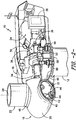
FIG. 2 illustrates a perspective view of a simplified, internal view of one embodiment of a nacelle of a wind turbine according to the present disclosure; -
FIG. 3 illustrates a partial, perspective view of one embodiment of hub of a wind turbine, particularly illustrating a hub crane assembly according to the present disclosure mounted thereto; -
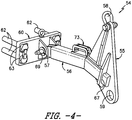
FIG. 4 illustrates a perspective view of one embodiment of an adjustable articulating arm of a hub crane assembly according to the present disclosure; -
FIG. 5 illustrates a partial, perspective view of one embodiment of hub of a wind turbine, particularly illustrating a hub crane assembly having an articulating arm in an initial position according to the present disclosure; -
FIG. 6 illustrates a front view of one embodiment of hub of a wind turbine, particularly illustrating a hub crane assembly according to the present disclosure mounted thereto; -
FIG. 7 illustrates a partial, perspective view of one embodiment of hub of a wind turbine, particularly illustrating a hub crane assembly having an articulating arm in a slightly rotated position according to the present disclosure; -
FIG. 8 illustrates a partial, perspective view of one embodiment of hub of a wind turbine, particularly illustrating a hub crane assembly having an articulating arm in a further rotated position such that the second hoist extends partially outside of the hub according to the present disclosure; -
FIG. 9 illustrates a partial, perspective view of one embodiment of hub of a wind turbine, particularly illustrating a hub crane assembly having an articulating arm in a maximum distance position with the second hoist extending completely outside of the hub according to the present disclosure; -
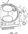
FIG. 10 illustrates a partial, perspective view of one embodiment of hub of a wind turbine, particularly illustrating a hub crane assembly having an articulating arm in a maximum distance position with a load attached thereto according to the present disclosure; -
FIG. 11 illustrates a partial, perspective view of one embodiment of hub of a wind turbine, particularly illustrating a hub crane assembly having an articulating arm in a minimum distance position with a load attached thereto according to the present disclosure; and -
FIG. 12 illustrates a flow diagram of one embodiment of a method for lifting or lowering a wind turbine component between a support surface and a hub of a wind turbine according to the present disclosure. - Reference now will be made in detail to embodiments of the invention, one or more examples of which are illustrated in the drawings. Each example is provided by way of explanation of the invention, not limitation of the invention. In fact, it will be apparent to those skilled in the art that various modifications and variations can be made in the present invention without departing from the scope of the invention. For instance, features illustrated or described as part of one embodiment can be used with another embodiment to yield a still further embodiment. Thus, it is intended that the present invention covers such modifications and variations as come within the scope of the appended claims and their equivalents.
- Generally, the present disclosure is directed to a hub crane assembly for a wind turbine. The hub crane assembly includes an adjustable articulating arm, first and second hoists, and a support component secured to the first hoist and a first attachment point of the articulating arm. As such, the first hoist is configured to rotate the articulating arm about the hinge point via the support component such that, as the articulating arm rotates, a clearance distance between the wind turbine and the articulating arm changes. Thus, the second hoist is configured with a load that is lifted and/or lowered from a support surface to the hub. Accordingly, the clearance distance is at a maximum as the load is lifted and is decreased when the load reaches the hub such than an operator can easily bring the load within the hub when it reaches the appropriate height.
- The present disclosure provides many advantages not present in the prior art. For example, the hub crane assembly can change the working radius (i.e. the clearance distance) such that it is possible to move the components forward and backwards during lifting and/or lowering thereof. As such, the distance can be increased when desired (i.e. to maintain distance from the tower during lifting/lowering) or decreased as needed (i.e. when the components need to be brought within the hub). As such, large cranes can be eliminated during certain lifting and/or lowering procedures. In addition, the hub crane assembly can be easily installed from within the hub, thereby eliminating dangerous installation procedures atop the wind turbine tower for operators.
- Referring now to the drawings,
FIG. 1 illustrates a perspective view of one embodiment of awind turbine 10 according to the present disclosure. As shown, thewind turbine 10 generally includes atower 12 extending from asupport surface 14, anacelle 16 mounted on thetower 12, and arotor 18 coupled to thenacelle 16. Therotor 18 includes arotatable hub 20 and at least onerotor blade 22 coupled to and extending outwardly from thehub 20. For example, in the illustrated embodiment, therotor 18 includes threerotor blades 22. However, in an alternative embodiment, therotor 18 may include more or less than threerotor blades 22. Eachrotor blade 22 may be spaced about thehub 20 to facilitate rotating therotor 18 to enable kinetic energy to be transferred from the wind into usable mechanical energy, and subsequently, electrical energy. For instance, thehub 20 may be rotatably coupled to an electric generator 24 (FIG. 2 ) positioned within thenacelle 16 to permit electrical energy to be produced. - The
wind turbine 10 may also include awind turbine controller 26 centralized within thenacelle 16. However, in other embodiments, thecontroller 26 may be located within any other component of thewind turbine 10 or at a location outside thewind turbine 10. Further, thecontroller 26 may be communicatively coupled to any number of the components of thewind turbine 10 in order to control the components. As such, thecontroller 26 may include a computer or other suitable processing unit. Thus, in several embodiments, thecontroller 26 may include suitable computer-readable instructions that, when implemented, configure thecontroller 26 to perform various different functions, such as receiving, transmitting and/or executing wind turbine control signals. - Referring now to
FIG. 2 , a simplified, internal view of one embodiment of thenacelle 16 of thewind turbine 10 shown inFIG. 1 is illustrated. As shown, thegenerator 24 may be coupled to therotor 18 for producing electrical power from the rotational energy generated by therotor 18. For example, as shown in the illustrated embodiment, therotor 18 may include arotor shaft 34 coupled to thehub 20 for rotation therewith. Therotor shaft 34 may, in turn, be rotatably coupled to agenerator shaft 36 of thegenerator 24 through agearbox 38. Further, thegearbox 38 is connected to abedplate support frame 48 by one or more torque supports 50. As is generally understood, therotor shaft 34 provides a low speed, high torque input to thegearbox 38 in response to rotation of therotor blades 22 and thehub 20. Thegearbox 38 then converts the low speed, high torque input to a high speed, low torque output to drive thegenerator shaft 36 and, thus, thegenerator 24. - Each
rotor blade 22 may also include apitch adjustment mechanism 32 configured to rotate eachrotor blade 22 about itspitch axis 28, depending on the wind speed and/or wind direction. As such, pitching theblades 22 directly affects the power output of thegenerator 24. More specifically, eachpitch adjustment mechanism 32 may include a pitch drive motor 40 (e.g., any suitable electric, hydraulic, or pneumatic motor), apitch drive gearbox 42, and apitch drive pinion 44. In such embodiments, thepitch drive motor 40 may be coupled to thepitch drive gearbox 42 so that thepitch drive motor 40 imparts mechanical force to thepitch drive gearbox 42. Similarly, thepitch drive gearbox 42 may be coupled to thepitch drive pinion 44 for rotation therewith. Thepitch drive pinion 44 may, in turn, be in rotational engagement with a pitch bearing 46 coupled between thehub 20 and acorresponding rotor blade 22 such that rotation of thepitch drive pinion 44 causes rotation of thepitch bearing 46. Thus, in such embodiments, rotation of thepitch drive motor 40 drives thepitch drive gearbox 42 and thepitch drive pinion 44, thereby rotating the pitch bearing 46 and therotor blade 22 about thepitch axis 28. Similarly, thewind turbine 10 may include one or moreyaw drive mechanisms 66 communicatively coupled to thecontroller 26, with each yaw drive mechanism(s) 66 being configured to change the angle of thenacelle 16 relative to the wind (e.g., by engaging a yaw bearing 68 of the wind turbine 10). - Referring now to
FIGS. 3-11 , various views of one embodiment of ahub crane assembly 52 mounted to awind turbine 10 according to the present disclosure is illustrated. As shown, thehub crane assembly 52 includes an adjustable articulatingarm 54, a first hoist 64, asupport component 65, and anoptional anchoring point 66. As shown particularly inFIGS. 3 and5-11 , the articulatingarm 54 is mounted on thehub 20 of thewind turbine 10 via ahinge point 57. In addition, as shown inFIG. 4 , the articulatingarm 54 may include afirst arm portion 55 and asecond arm portion 56. More specifically, as shown, the first andsecond arm portions attachment location 61. For example, as shown inFIG. 4 , the fixedattachment location 61 may include thesecond arm portion 56 of the articulatingarm 54 being secured within aslot 67 defined in thefirst arm portion 55. As such, an end of thesecond arm portion 56 may fit within theslot 67 of thefirst arm portion 55 and secured therein, e.g. via mechanical fasteners, adhesives, welding, or similar. In alterative embodiments, the first andsecond arm portions slot 67. In addition, as shown particularly inFIG. 4 , the articulatingarm 54 may also include a handle 73 (e.g. mounted to the second arm portion 56) such that an operator can easily lift and move the articulatingarm 54. - Referring particularly to
FIG. 6 , the articulatingarm 54 may be mounted on thehub 20 of thewind turbine 10 at a first height H1, whereas the first hoist 64 is mounted at a second height H2 of thewind turbine 10. Further, as shown in the illustrated embodiment, the second height H2 is greater than the first height H1. In addition, as shown generally inFIGS. 3 and4-11 , the articulatingarm 54 may be mountable to a front location of thehub 20, whereas the first hoist 64 may be mountable to a top location of at least one of thehub 20 or thenacelle 16 of thewind turbine 10. As such, the articulatingarm 54 may be easily mounted to the front location from within thehub 20 such that an operator is not required to leave thehub 20. - In further embodiments, as shown in
FIGS. 3 and4 , the adjustable articulatingarm 54 may be mounted to thehub 20 via a mountingplate 60. More specifically, as shown, thesecond arm portion 56 of the articulatingarm 54 may be mounted to thehub 20 via the mountingplate 60 at thehinge point 57. For example, the mountingplate 60 may include a plurality of bolt holes and correspondingbolts 62 that can be secured via a plurality of nuts (not shown) from inside thehub 20. In addition, as shown, the mountingplate 60 may include thehinge point 57. Thus, as shown inFIG. 4 , thesecond arm portion 56 of the articulatingarm 54 may be secured to the mountingplate 60 at thehinge point 57 via apin 69. - Referring particularly to
FIGS. 3 and7-11 , thesupport component 65 is secured to the first hoist 64 and afirst attachment point 58 of the articulatingarm 54. More specifically, as shown, thesupport component 65 may include a strap, a sling, or similar. In additional embodiments, theanchoring point 66 is configured to secure the first hoist 64 to thehub 20 of thewind turbine 10. More particularly, in certain embodiments, theanchoring point 66 may include a swivel bolt or any other suitable fastener so as to further secure the first hoist 64 to thehub 20. - Referring now to
FIGS. 7-11 , thehub crane assembly 52 may also include a second hoist 68 secured to the articulatingarm 54 at an opposing,second attachment point 59 of thefirst arm portion 55. In such embodiments, the second hoist 68 is configured to lift or lower aload 70 from a support surface (e.g. support surface 14) to thehub 20. It should be understood that the first andsecond hoists second hoists - Thus, as shown generally in
FIGS. 3-12 , the first hoist 64 is configured to rotate the articulatingarm 54 about thehinge point 57 via thesupport component 65 such that, as the articulatingarm 54 rotates, a clearance distance (e.g. as illustrated bydistances 72 and 74) between thewind turbine 10 and the articulating arm 54 (and also the load 70) changes. More specifically, as shown inFIG. 12 , a flow diagram of one embodiment of amethod 100 for lifting or lowering a wind turbine component between a support surface (e.g. support surface 14) and ahub 20 of awind turbine 10 using thehub crane assembly 52 of the present disclosure is illustrated. - As shown at 102, the
method 100 includes securing the adjustable articulatingarm 54 at the first height H1 on thehub 20 of thewind turbine 10. More specifically, as shown inFIGS. 5 and6 , the articulatingarm 54 may be installed in a first position closest to thehub 20. This position allows an operator to easily install the mountingplate 60 as described above and secure the articulatingarm 54 thereto without having to leave the inside of thehub 20. - As shown at 104, the
method 100 includes securing a first hoist 64 at a second height H2 of thewind turbine 10, wherein the second height H2 is greater than the first height H1. For example, as shown inFIG. 7 , the first hoist 64 can also be installed from inside thehub 20 to a location atop thehub 20. - As shown at 106, the
method 100 includes connecting asupport component 65 to the first hoist 64 and afirst attachment point 58 of the articulatingarm 54. For example, thesupport component 65 may be routed from the first hoist 64 mounted atop thehub 20 to the articulatingarm 54 and secured to thefirst attachment point 58. As shown at 108, themethod 100 includes securing a second hoist 68 to asecond attachment point 59 of the articulatingarm 54. In addition, as shown, an operator may also secure the second hoist 68 to thesecond attachment point 59 from inside of thehub 20. - Referring still to
FIG. 12 , as shown at 110, themethod 100 includes securing aload 70 to the second hoist 65 via at least one support line 76 (FIGS 10 and11 ). Thus, as shown at 112, themethod 100 includes lifting or lowering, via coordinated hoist operation of the first andsecond hoists arm 54 and theload 70. Accordingly, as theload 70 is lifted or lowered via the second hoist 68, the first hoist 64 rotates the articulatingarm 54 about thehinge point 57 such that theclearance distance load 70 and the wind turbine 10 (e.g. the tower 12) changes. More specifically, as shown, as the first hoist 64 rotates the articulatingarm 54 upwards, the second hoist 68 is suspended outside of thehub 20 and the articulatingarm 54 extends outward from thehub 20 at its maximum length. (See e.g.,FIGS. 8-10 ; distance 72). Thus, as the load is lifted and/or lowered, theclearance distance 72 is maximized via the adjustable articulatingarm 54 so as to prevent collisions between theload 70 and thetower 12 of thewind turbine 10. - In addition, as shown in
FIGS. 10 and11 , the articulatingarm 54 continues to rotate upwards towards the first hoist 54 until theload 70 has reached anopening 30 of thehub 20. At this time, an operator can easily retrieve theload 70 from thesupport line 76 and bring the load within thehub 20. It should be understood that theload 70 described herein may include any suitable wind turbine components, such as, for example, thepitch drive mechanism 32 and/or any other components. - This written description uses examples to disclose the invention, including the best mode, and also to enable any person skilled in the art to practice the invention, including making and using any devices or systems and performing any incorporated methods. The patentable scope of the invention is defined by the claims, and may include other examples that occur to those skilled in the art.
Reference Character Component 10 Wind Turbine 12 Tower 14 Support Surface 16 Nacelle 18 Rotor 20 Hub 22 Rotor Blades 24 Generator 26 Controller 28 Pitch Axis 30 Opening 32 Pitch Drive Mechanism 34 Rotor Shaft 36 Generator Shaft 38 Gearbox 40 Pitch Drive Motor 42 Pitch Drive Gearbox 44 Pitch Drive Pinion 46 Pitch Bearing 48 Bedplate Support Frame 50 Torque Supports 52 Hub Crane Assembly 54 Articulating Arm 55 First Arm Portion 56 Second Arm Portion 57 Hinge Point 58 First Attachment Point 59 Second Attachment Point 60 Mounting Plate 61 Fixed Attachment Location 62 Bolts 63 Bolt Holes 64 First Hoist 65 Support Component 66 Anchoring Point 67 Slot 69 Pin 68 Second Hoist 69 Pin 70 Load 73 Handle 72 First Distance 74 Second Distance 76 Support Line 100 Method 102 Method Step 104 Method Step 106 Method Step 108 Method Step 110 Method Step 112 Method Step
Claims (15)
- A hub crane assembly (52) for a wind turbine (10), comprising:an adjustable articulating arm (54) mountable at a first height on a hub (20) of the wind turbine (10) at a hinge point (57);a first hoist (64) mountable at a second height of the wind turbine (10), the second height being greater than the first height; and,a support component (65) secured to the first hoist (64) and a first attachment point of the articulating arm (54),wherein the first hoist (64) is configured to rotate the articulating arm (54) about the hinge point (57) via the support component (65) such that, as the articulating arm (54) rotates, a clearance distance between the wind turbine (10) and the articulating arm (54) changes.
- The hub crane assembly (52) of claim 1, further comprising a second hoist (68) secured to the articulating arm (54) at an opposing, second attachment point (59), the second hoist (68) configured to lift or lower a load (70) from a support surface (14) to the hub (20).
- The hub crane assembly (52) of claims 1 or 2, wherein the articulating arm (54) comprises a first arm portion (55) and a second arm portion (56), the first and second arm portions (55, 56) secured together at a fixed attachment location (61).
- The hub crane assembly (52) of claim 3, wherein the fixed attachment location (61) comprises the second arm portion (56) of the articulating arm (54) secured within a slot (67) defined in the first arm portion (55).
- The hub crane assembly (52) of claim 3, wherein the second arm portion (56) of the articulating arm (54) is mounted to the hub (20) via a mounting plate (60) at the hinge point (57).
- The hub crane assembly (52) of any of the preceding claims, further comprising an anchoring point (66) configured to secure the first hoist (64) to the hub (20) of the wind turbine (10).
- The hub crane assembly (52) of claim 6, wherein the anchoring point (66) comprising a swivel bolt.
- The hub crane assembly (52) of any of the preceding claims, wherein the articulating arm (54) is mountable to a front location of the hub (20).
- The hub crane assembly (52) of any of the preceding claims, wherein the first hoist (64) is mountable to a top location of at least one of the hub (20) or a nacelle (16) of the wind turbine (10).
- The hub crane assembly (52) of any of the preceding claims, wherein the support component (65) comprises at least one of a strap or a sling.
- A method (100) for lifting or lowering a wind turbine (10) component between a support surface (14) and a hub (20) of a wind turbine (10) using a hub cranes assembly according to any of claims 1 - 10, the method (100) comprising:securing an adjustable articulating arm (54) at a first height on the hub (20) of the wind turbine (10);securing a first hoist (64) at a second height of the wind turbine (10), the second height being greater than the first height;connecting a support component (65) to the first hoist (64) and a first attachment point (58) of the articulating arm (54);securing a second hoist (68) to a second attachment point (59) of the articulating arm (54);securing a load (70) to the second hoist (68) via at least one strap; and,lifting or lowering, via coordinated hoist operation of the first (64) and second (68) hoists, the articulating arm (54) and the load (70),wherein, as the load (70) is lifted or lowered via the second hoist (68), the first hoist (64) rotates the articulating arm (54) about a hinge point (57) such that a clearance distance between the load (70) and the wind turbine (10) changes.
- The method (100) of claim 11, further comprising securing the adjustable articulating arm (54) at the first height on the hub via a mounting plate (60) from within the hub (20).
- A wind turbine (10), comprising:a tower (12) mounted to a support surface (14);a nacelle (16) mounted atop the tower (12);a rotor (18) mounted to the nacelle (16), the rotor (18) comprising a rotatable hub (20) having one or more rotor blades (22) mounted thereto; and,a hub crane assembly (52) according to claim 1.
- The wind turbine (10) of claim 13, further comprising a second hoist (68) secured to the articulating arm (54) at an opposing, second attachment point (59), the second hoist (68) configured to lift or lower a load (70) from a support surface (14) to the hub (20).
- The wind turbine (10) of claims 13 or 14, wherein the articulating arm (54) comprises a first arm portion (55) and a second arm portion (56), the first and second arm portions (55, 56) secured together at a fixed attachment location (61), wherein the second arm portion (56) of the articulating arm (54) is mounted to the hub via a mounting plate (60) at the hinge point (57).
Priority Applications (4)
| Application Number | Priority Date | Filing Date | Title |
|---|---|---|---|
| EP17382156.2A EP3382200B1 (en) | 2017-03-29 | 2017-03-29 | Hub crane assembly for a wind turbine |
| ES17382156T ES2876008T3 (en) | 2017-03-29 | 2017-03-29 | Hub crane assembly for a wind turbine |
| DK17382156.2T DK3382200T3 (en) | 2017-03-29 | 2017-03-29 | HUB CRANE DEVICE FOR A WIND TURBINE |
| US15/967,782 US10801473B2 (en) | 2017-03-29 | 2018-05-01 | Hub crane assembly for a wind turbine |
Applications Claiming Priority (1)
| Application Number | Priority Date | Filing Date | Title |
|---|---|---|---|
| EP17382156.2A EP3382200B1 (en) | 2017-03-29 | 2017-03-29 | Hub crane assembly for a wind turbine |
Publications (2)
| Publication Number | Publication Date |
|---|---|
| EP3382200A1 EP3382200A1 (en) | 2018-10-03 |
| EP3382200B1 true EP3382200B1 (en) | 2020-12-30 |
Family
ID=58501419
Family Applications (1)
| Application Number | Title | Priority Date | Filing Date |
|---|---|---|---|
| EP17382156.2A Active EP3382200B1 (en) | 2017-03-29 | 2017-03-29 | Hub crane assembly for a wind turbine |
Country Status (4)
| Country | Link |
|---|---|
| US (1) | US10801473B2 (en) |
| EP (1) | EP3382200B1 (en) |
| DK (1) | DK3382200T3 (en) |
| ES (1) | ES2876008T3 (en) |
Families Citing this family (3)
| Publication number | Priority date | Publication date | Assignee | Title |
|---|---|---|---|---|
| CN109139394B (en) * | 2018-10-31 | 2021-02-26 | 北京金风科创风电设备有限公司 | Hub and impeller of wind generating set and mounting method of variable pitch control component |
| WO2021077207A1 (en) * | 2019-10-22 | 2021-04-29 | LiftWerx Holdings Inc. | Lifting system for a rotor blade of a wind turbine |
| US11946454B2 (en) * | 2021-11-24 | 2024-04-02 | Ge Infrastructure Technology Llc | Mounting tool for fastener assembly and disassembly within wind turbine hubs |
Family Cites Families (46)
| Publication number | Priority date | Publication date | Assignee | Title |
|---|---|---|---|---|
| AT401674B (en) | 1994-09-26 | 1996-11-25 | Hehenberger Gerald Dipl Ing | WIND TURBINE |
| DE10224439C5 (en) | 2002-06-01 | 2009-12-31 | Aloys Wobben | Method for assembly / disassembly of components of a wind turbine |
| DE10303555B4 (en) | 2003-01-29 | 2007-01-25 | Aloys Wobben | Method for craneless mounting of a rotor blade of a wind energy plant |
| DE102004056340B4 (en) | 2004-11-22 | 2010-11-18 | Repower Systems Ag | Device and method for mounting and / or dismantling a component of a wind turbine |
| WO2008069818A1 (en) | 2006-12-08 | 2008-06-12 | General Electric Company | Portable hub crane for wind turbine components |
| ES2322000B1 (en) | 2006-12-14 | 2010-03-11 | GAMESA INNOVATION & TECHNOLOGY, S.L. | A METHOD FOR MOUNTING THE ROTOR OF AN AIRBRUSHER. |
| US8403620B2 (en) | 2007-01-24 | 2013-03-26 | Vestas Wind Systems A/S | Method for moving a wind turbine component, such as a wind turbine hub, from a transportation position to a wind turbine assembly position in or on the nacelle, the main shaft or turbine hub, a handling unit, a wind turbine hub and use hereof |
| CN201343379Y (en) | 2008-02-04 | 2009-11-11 | 大连华锐股份有限公司 | Crane used for maintenance of large-size wind power equipment |
| US8104631B2 (en) * | 2008-07-24 | 2012-01-31 | General Electric Company | Portable crane system for wind turbine components |
| US20100139062A1 (en) | 2009-02-25 | 2010-06-10 | General Electric Company | Lowering and raising a single wind turbine rotor blade from six-o'clock position |
| DK2226502T3 (en) | 2009-03-03 | 2013-03-25 | Siemens Ag | Method and device for installing a wind turbine |
| US20100254813A1 (en) | 2009-04-02 | 2010-10-07 | Frontier Pro Services | Winch servicing of wind turbines |
| KR101054919B1 (en) | 2009-04-03 | 2011-08-05 | 주식회사 디엠에스 | Wind generator |
| US8118552B2 (en) | 2009-10-06 | 2012-02-21 | General Electric Company | Apparatus and method for manipulating a component of a wind turbine |
| CN101929443A (en) | 2009-10-26 | 2010-12-29 | 华锐风电科技(集团)股份有限公司 | Blade self-replacement device of wind driven generator set and working method thereof |
| WO2011064659A2 (en) | 2009-11-30 | 2011-06-03 | Clipper Windpower, Inc. | Wind turbine blade lowering apparatus |
| WO2011082710A1 (en) | 2010-01-07 | 2011-07-14 | Vestas Wind Systems A/S | Method of lifting a wind turbine component toward a top portion of a wind turbine tower |
| EP2369174B1 (en) | 2010-03-09 | 2012-11-28 | Lm Glasfiber A/S | A method of craneless mounting or demounting of a wind turbine blade |
| GB2483677B (en) | 2010-09-15 | 2014-04-16 | Vestas Wind Sys As | An apparatus for and method of mounting wind turbine blades on a wind turbine tower |
| US8789274B2 (en) | 2010-09-23 | 2014-07-29 | Northern Power Systems, Inc. | Method and system for servicing a horizontal-axis wind power unit |
| WO2012065613A1 (en) | 2010-11-18 | 2012-05-24 | Vestas Wind Systems A/S | Method for craneless wind turbine blade handling via a turbine hub |
| US20110206510A1 (en) | 2010-12-20 | 2011-08-25 | Reinhard Langen | Modular rotor blade and method for mounting a wind turbine |
| US8807923B2 (en) | 2011-02-07 | 2014-08-19 | Vestas Wind Systems A/S | Access apparatus for a wind turbine and method of using same |
| KR101235358B1 (en) | 2011-02-22 | 2013-02-20 | 주식회사 디엠에스 | Wind power generator |
| DK2686550T3 (en) | 2011-03-17 | 2016-10-24 | Vestas Wind Sys As | An apparatus for gaining access to the nacelle of a wind turbine and associated methods |
| KR101362936B1 (en) | 2012-01-17 | 2014-02-14 | 삼성중공업 주식회사 | Apparatus for moving blade of wind turbine generator, method for repairing the pitch bearing using the same and wind turbine generator having the same |
| EP2672106B1 (en) | 2012-06-04 | 2020-08-12 | Nordex Energy Spain, S.A.U. | System and method for assembling and disassembling components from a wind power turbine |
| WO2014020638A1 (en) | 2012-07-31 | 2014-02-06 | Mitsubishi Heavy Industries, Ltd. | Track system for a wind turbine generator |
| EP2724019B1 (en) | 2012-07-31 | 2015-04-08 | Mitsubishi Heavy Industries, Ltd. | Crane arrangement |
| WO2014033682A1 (en) | 2012-08-30 | 2014-03-06 | High Wind N.V. | Device and method for assembling a structure |
| US9745953B2 (en) | 2012-10-23 | 2017-08-29 | General Electric Company | Method and system for replacing a single wind turbine blade |
| CN202880704U (en) | 2012-11-14 | 2013-04-17 | 神华集团有限责任公司 | Lifting tool for hub of wind turbine |
| EP2935080B1 (en) | 2012-12-20 | 2018-02-14 | High Wind N.V. | Device and method for placing components of a structure |
| CN203079518U (en) | 2013-01-16 | 2013-07-24 | 江苏新誉重工科技有限公司 | Device for lifting large component inside wind wheel of wind generator set |
| US9651020B2 (en) * | 2013-09-24 | 2017-05-16 | General Electric Company | Portable crane for use in wind turbines |
| JP2015075037A (en) | 2013-10-09 | 2015-04-20 | 三菱重工業株式会社 | Wind turbine blade attaching/detaching method and device |
| AU2014361293B2 (en) | 2013-12-10 | 2017-06-15 | Pp Energy Aps | Fixation device for servicing wind turbine components |
| JP6290647B2 (en) * | 2014-02-19 | 2018-03-07 | 三菱重工業株式会社 | Maintenance device and maintenance method for wind power generator |
| US9638163B2 (en) | 2014-02-20 | 2017-05-02 | General Electric Company | Methods and systems for removing and/or installing wind turbine rotor blades |
| US9964095B2 (en) | 2014-04-21 | 2018-05-08 | General Electric Company | Method and system for servicing wind turbine rotor |
| US10934994B2 (en) | 2014-04-30 | 2021-03-02 | Windcare India Pvt Ltd | Method and system for de-erection and re-erection of a blade of a wind turbine |
| DK178406B1 (en) | 2014-06-12 | 2016-02-08 | Envision Energy Denmark Aps | Lifting device for rotor assembly and method thereof |
| ES2556997B1 (en) | 2014-07-07 | 2016-12-12 | Gamesa Innovation & Technology, S.L. | Blade replacement method and device in wind turbines |
| US9850880B2 (en) | 2014-11-20 | 2017-12-26 | General Electric Company | System for servicing wind turbine rotor |
| CN105984818A (en) | 2015-03-02 | 2016-10-05 | 上海电气风电设备有限公司 | Novel internal hoisting device for wind turbine generator hub |
| CN204675721U (en) | 2015-03-02 | 2015-09-30 | 上海电气风电设备有限公司 | Lifting appliance in a kind of novel wind-powered machine unit hub |
-
2017
- 2017-03-29 EP EP17382156.2A patent/EP3382200B1/en active Active
- 2017-03-29 DK DK17382156.2T patent/DK3382200T3/en active
- 2017-03-29 ES ES17382156T patent/ES2876008T3/en active Active
-
2018
- 2018-05-01 US US15/967,782 patent/US10801473B2/en active Active
Non-Patent Citations (1)
| Title |
|---|
| None * |
Also Published As
| Publication number | Publication date |
|---|---|
| EP3382200A1 (en) | 2018-10-03 |
| US10801473B2 (en) | 2020-10-13 |
| US20180297822A1 (en) | 2018-10-18 |
| DK3382200T3 (en) | 2021-03-29 |
| ES2876008T3 (en) | 2021-11-11 |
Similar Documents
| Publication | Publication Date | Title |
|---|---|---|
| EP3001029B1 (en) | Counterweight systems for a wind turbine and methods | |
| US9651020B2 (en) | Portable crane for use in wind turbines | |
| EP3431751B1 (en) | System and method for suspending a rotor blade of a wind turbine uptower | |
| US10443572B2 (en) | System and method for removing or installing a main shaft of a wind turbine | |
| US10801473B2 (en) | Hub crane assembly for a wind turbine | |
| EP3502465B1 (en) | Hoisting accessories for wind turbines, kits and methods | |
| CN105905813A (en) | Blade hoisting tool for wind-driven generator | |
| EP3615795B1 (en) | System and method for removing or installing a main shaft of a wind turbine with rigging | |
| EP3615793B1 (en) | System and method for removing or installing a main shaft of a wind turbine with a push/pull system configured at an end of the main shaft | |
| US10641042B2 (en) | External ladder assembly for wind turbine nacelle | |
| US10570888B2 (en) | Working platform within a nacelle of a wind turbine | |
| US9803739B2 (en) | Gearbox adjustment system | |
| US11965479B2 (en) | System and method for repairing a gearbox of a wind turbine uptower | |
| US11384740B2 (en) | System and method for locking of a rotor of a wind turbine during extended maintenance | |
| US20180313334A1 (en) | Hoistable platform assembly within a nacelle of a wind turbine | |
| US11353007B2 (en) | Method of mounting a nacelle of a wind turbine and assembling set of parts of a wind turbine | |
| US11686291B2 (en) | Method of mounting blades to a rotor hub of a wind turbine | |
| EP4019770A1 (en) | Blade lifting assembly for mounting a blade to or unmounting a blade from a rotor hub of a wind turbine | |
| EP3364023B1 (en) | System and method for removing or installing a main shaft of a wind turbine | |
| WO2023148255A1 (en) | Blade segment for a rotor blade of a wind turbine |
Legal Events
| Date | Code | Title | Description |
|---|---|---|---|
| PUAI | Public reference made under article 153(3) epc to a published international application that has entered the european phase |
Free format text: ORIGINAL CODE: 0009012 |
|
| STAA | Information on the status of an ep patent application or granted ep patent |
Free format text: STATUS: REQUEST FOR EXAMINATION WAS MADE |
|
| 17P | Request for examination filed |
Effective date: 20170329 |
|
| AK | Designated contracting states |
Kind code of ref document: A1 Designated state(s): AL AT BE BG CH CY CZ DE DK EE ES FI FR GB GR HR HU IE IS IT LI LT LU LV MC MK MT NL NO PL PT RO RS SE SI SK SM TR |
|
| AX | Request for extension of the european patent |
Extension state: BA ME |
|
| RBV | Designated contracting states (corrected) |
Designated state(s): AL AT BE BG CH CY CZ DE DK EE ES FI FR GB GR HR HU IE IS IT LI LT LU LV MC MK MT NL NO PL PT RO RS SE SI SK SM TR |
|
| GRAP | Despatch of communication of intention to grant a patent |
Free format text: ORIGINAL CODE: EPIDOSNIGR1 |
|
| STAA | Information on the status of an ep patent application or granted ep patent |
Free format text: STATUS: GRANT OF PATENT IS INTENDED |
|
| INTG | Intention to grant announced |
Effective date: 20200603 |
|
| GRAS | Grant fee paid |
Free format text: ORIGINAL CODE: EPIDOSNIGR3 |
|
| GRAJ | Information related to disapproval of communication of intention to grant by the applicant or resumption of examination proceedings by the epo deleted |
Free format text: ORIGINAL CODE: EPIDOSDIGR1 |
|
| GRAL | Information related to payment of fee for publishing/printing deleted |
Free format text: ORIGINAL CODE: EPIDOSDIGR3 |
|
| STAA | Information on the status of an ep patent application or granted ep patent |
Free format text: STATUS: REQUEST FOR EXAMINATION WAS MADE |
|
| INTC | Intention to grant announced (deleted) | ||
| GRAJ | Information related to disapproval of communication of intention to grant by the applicant or resumption of examination proceedings by the epo deleted |
Free format text: ORIGINAL CODE: EPIDOSDIGR1 |
|
| GRAL | Information related to payment of fee for publishing/printing deleted |
Free format text: ORIGINAL CODE: EPIDOSDIGR3 |
|
| GRAP | Despatch of communication of intention to grant a patent |
Free format text: ORIGINAL CODE: EPIDOSNIGR1 |
|
| STAA | Information on the status of an ep patent application or granted ep patent |
Free format text: STATUS: GRANT OF PATENT IS INTENDED |
|
| GRAA | (expected) grant |
Free format text: ORIGINAL CODE: 0009210 |
|
| STAA | Information on the status of an ep patent application or granted ep patent |
Free format text: STATUS: THE PATENT HAS BEEN GRANTED |
|
| INTG | Intention to grant announced |
Effective date: 20201113 |
|
| AK | Designated contracting states |
Kind code of ref document: B1 Designated state(s): AL AT BE BG CH CY CZ DE DK EE ES FI FR GB GR HR HU IE IS IT LI LT LU LV MC MK MT NL NO PL PT RO RS SE SI SK SM TR |
|
| REG | Reference to a national code |
Ref country code: GB Ref legal event code: FG4D |
|
| REG | Reference to a national code |
Ref country code: AT Ref legal event code: REF Ref document number: 1350176 Country of ref document: AT Kind code of ref document: T Effective date: 20210115 |
|
| REG | Reference to a national code |
Ref country code: DE Ref legal event code: R096 Ref document number: 602017030394 Country of ref document: DE |
|
| REG | Reference to a national code |
Ref country code: IE Ref legal event code: FG4D |
|
| REG | Reference to a national code |
Ref country code: DK Ref legal event code: T3 Effective date: 20210325 |
|
| PG25 | Lapsed in a contracting state [announced via postgrant information from national office to epo] |
Ref country code: RS Free format text: LAPSE BECAUSE OF FAILURE TO SUBMIT A TRANSLATION OF THE DESCRIPTION OR TO PAY THE FEE WITHIN THE PRESCRIBED TIME-LIMIT Effective date: 20201230 Ref country code: NO Free format text: LAPSE BECAUSE OF FAILURE TO SUBMIT A TRANSLATION OF THE DESCRIPTION OR TO PAY THE FEE WITHIN THE PRESCRIBED TIME-LIMIT Effective date: 20210330 Ref country code: GR Free format text: LAPSE BECAUSE OF FAILURE TO SUBMIT A TRANSLATION OF THE DESCRIPTION OR TO PAY THE FEE WITHIN THE PRESCRIBED TIME-LIMIT Effective date: 20210331 Ref country code: FI Free format text: LAPSE BECAUSE OF FAILURE TO SUBMIT A TRANSLATION OF THE DESCRIPTION OR TO PAY THE FEE WITHIN THE PRESCRIBED TIME-LIMIT Effective date: 20201230 |
|
| REG | Reference to a national code |
Ref country code: AT Ref legal event code: MK05 Ref document number: 1350176 Country of ref document: AT Kind code of ref document: T Effective date: 20201230 |
|
| PG25 | Lapsed in a contracting state [announced via postgrant information from national office to epo] |
Ref country code: SE Free format text: LAPSE BECAUSE OF FAILURE TO SUBMIT A TRANSLATION OF THE DESCRIPTION OR TO PAY THE FEE WITHIN THE PRESCRIBED TIME-LIMIT Effective date: 20201230 Ref country code: BG Free format text: LAPSE BECAUSE OF FAILURE TO SUBMIT A TRANSLATION OF THE DESCRIPTION OR TO PAY THE FEE WITHIN THE PRESCRIBED TIME-LIMIT Effective date: 20210330 Ref country code: LV Free format text: LAPSE BECAUSE OF FAILURE TO SUBMIT A TRANSLATION OF THE DESCRIPTION OR TO PAY THE FEE WITHIN THE PRESCRIBED TIME-LIMIT Effective date: 20201230 |
|
| REG | Reference to a national code |
Ref country code: NL Ref legal event code: MP Effective date: 20201230 |
|
| PG25 | Lapsed in a contracting state [announced via postgrant information from national office to epo] |
Ref country code: HR Free format text: LAPSE BECAUSE OF FAILURE TO SUBMIT A TRANSLATION OF THE DESCRIPTION OR TO PAY THE FEE WITHIN THE PRESCRIBED TIME-LIMIT Effective date: 20201230 |
|
| REG | Reference to a national code |
Ref country code: LT Ref legal event code: MG9D |
|
| PG25 | Lapsed in a contracting state [announced via postgrant information from national office to epo] |
Ref country code: SK Free format text: LAPSE BECAUSE OF FAILURE TO SUBMIT A TRANSLATION OF THE DESCRIPTION OR TO PAY THE FEE WITHIN THE PRESCRIBED TIME-LIMIT Effective date: 20201230 Ref country code: PT Free format text: LAPSE BECAUSE OF FAILURE TO SUBMIT A TRANSLATION OF THE DESCRIPTION OR TO PAY THE FEE WITHIN THE PRESCRIBED TIME-LIMIT Effective date: 20210430 Ref country code: RO Free format text: LAPSE BECAUSE OF FAILURE TO SUBMIT A TRANSLATION OF THE DESCRIPTION OR TO PAY THE FEE WITHIN THE PRESCRIBED TIME-LIMIT Effective date: 20201230 Ref country code: CZ Free format text: LAPSE BECAUSE OF FAILURE TO SUBMIT A TRANSLATION OF THE DESCRIPTION OR TO PAY THE FEE WITHIN THE PRESCRIBED TIME-LIMIT Effective date: 20201230 Ref country code: EE Free format text: LAPSE BECAUSE OF FAILURE TO SUBMIT A TRANSLATION OF THE DESCRIPTION OR TO PAY THE FEE WITHIN THE PRESCRIBED TIME-LIMIT Effective date: 20201230 Ref country code: LT Free format text: LAPSE BECAUSE OF FAILURE TO SUBMIT A TRANSLATION OF THE DESCRIPTION OR TO PAY THE FEE WITHIN THE PRESCRIBED TIME-LIMIT Effective date: 20201230 |
|
| PG25 | Lapsed in a contracting state [announced via postgrant information from national office to epo] |
Ref country code: PL Free format text: LAPSE BECAUSE OF FAILURE TO SUBMIT A TRANSLATION OF THE DESCRIPTION OR TO PAY THE FEE WITHIN THE PRESCRIBED TIME-LIMIT Effective date: 20201230 Ref country code: AT Free format text: LAPSE BECAUSE OF FAILURE TO SUBMIT A TRANSLATION OF THE DESCRIPTION OR TO PAY THE FEE WITHIN THE PRESCRIBED TIME-LIMIT Effective date: 20201230 |
|
| PG25 | Lapsed in a contracting state [announced via postgrant information from national office to epo] |
Ref country code: IS Free format text: LAPSE BECAUSE OF FAILURE TO SUBMIT A TRANSLATION OF THE DESCRIPTION OR TO PAY THE FEE WITHIN THE PRESCRIBED TIME-LIMIT Effective date: 20210430 |
|
| REG | Reference to a national code |
Ref country code: DE Ref legal event code: R097 Ref document number: 602017030394 Country of ref document: DE |
|
| PG25 | Lapsed in a contracting state [announced via postgrant information from national office to epo] |
Ref country code: MC Free format text: LAPSE BECAUSE OF FAILURE TO SUBMIT A TRANSLATION OF THE DESCRIPTION OR TO PAY THE FEE WITHIN THE PRESCRIBED TIME-LIMIT Effective date: 20201230 Ref country code: IT Free format text: LAPSE BECAUSE OF FAILURE TO SUBMIT A TRANSLATION OF THE DESCRIPTION OR TO PAY THE FEE WITHIN THE PRESCRIBED TIME-LIMIT Effective date: 20201230 Ref country code: AL Free format text: LAPSE BECAUSE OF FAILURE TO SUBMIT A TRANSLATION OF THE DESCRIPTION OR TO PAY THE FEE WITHIN THE PRESCRIBED TIME-LIMIT Effective date: 20201230 |
|
| REG | Reference to a national code |
Ref country code: CH Ref legal event code: PL |
|
| PLBE | No opposition filed within time limit |
Free format text: ORIGINAL CODE: 0009261 |
|
| STAA | Information on the status of an ep patent application or granted ep patent |
Free format text: STATUS: NO OPPOSITION FILED WITHIN TIME LIMIT |
|
| REG | Reference to a national code |
Ref country code: ES Ref legal event code: FG2A Ref document number: 2876008 Country of ref document: ES Kind code of ref document: T3 Effective date: 20211111 |
|
| GBPC | Gb: european patent ceased through non-payment of renewal fee |
Effective date: 20210330 |
|
| 26N | No opposition filed |
Effective date: 20211001 |
|
| REG | Reference to a national code |
Ref country code: BE Ref legal event code: MM Effective date: 20210331 |
|
| PG25 | Lapsed in a contracting state [announced via postgrant information from national office to epo] |
Ref country code: FR Free format text: LAPSE BECAUSE OF NON-PAYMENT OF DUE FEES Effective date: 20210331 Ref country code: GB Free format text: LAPSE BECAUSE OF NON-PAYMENT OF DUE FEES Effective date: 20210330 Ref country code: IE Free format text: LAPSE BECAUSE OF NON-PAYMENT OF DUE FEES Effective date: 20210329 Ref country code: LU Free format text: LAPSE BECAUSE OF NON-PAYMENT OF DUE FEES Effective date: 20210329 Ref country code: LI Free format text: LAPSE BECAUSE OF NON-PAYMENT OF DUE FEES Effective date: 20210331 Ref country code: CH Free format text: LAPSE BECAUSE OF NON-PAYMENT OF DUE FEES Effective date: 20210331 |
|
| PG25 | Lapsed in a contracting state [announced via postgrant information from national office to epo] |
Ref country code: SI Free format text: LAPSE BECAUSE OF FAILURE TO SUBMIT A TRANSLATION OF THE DESCRIPTION OR TO PAY THE FEE WITHIN THE PRESCRIBED TIME-LIMIT Effective date: 20201230 |
|
| PG25 | Lapsed in a contracting state [announced via postgrant information from national office to epo] |
Ref country code: IS Free format text: LAPSE BECAUSE OF FAILURE TO SUBMIT A TRANSLATION OF THE DESCRIPTION OR TO PAY THE FEE WITHIN THE PRESCRIBED TIME-LIMIT Effective date: 20210430 |
|
| PG25 | Lapsed in a contracting state [announced via postgrant information from national office to epo] |
Ref country code: BE Free format text: LAPSE BECAUSE OF NON-PAYMENT OF DUE FEES Effective date: 20210331 |
|
| PGFP | Annual fee paid to national office [announced via postgrant information from national office to epo] |
Ref country code: DK Payment date: 20230221 Year of fee payment: 7 |
|
| PGFP | Annual fee paid to national office [announced via postgrant information from national office to epo] |
Ref country code: DE Payment date: 20230221 Year of fee payment: 7 |
|
| PG25 | Lapsed in a contracting state [announced via postgrant information from national office to epo] |
Ref country code: NL Free format text: LAPSE BECAUSE OF NON-PAYMENT OF DUE FEES Effective date: 20201230 Ref country code: CY Free format text: LAPSE BECAUSE OF FAILURE TO SUBMIT A TRANSLATION OF THE DESCRIPTION OR TO PAY THE FEE WITHIN THE PRESCRIBED TIME-LIMIT Effective date: 20201230 |
|
| P01 | Opt-out of the competence of the unified patent court (upc) registered |
Effective date: 20230530 |
|
| PG25 | Lapsed in a contracting state [announced via postgrant information from national office to epo] |
Ref country code: SM Free format text: LAPSE BECAUSE OF FAILURE TO SUBMIT A TRANSLATION OF THE DESCRIPTION OR TO PAY THE FEE WITHIN THE PRESCRIBED TIME-LIMIT Effective date: 20201230 Ref country code: HU Free format text: LAPSE BECAUSE OF FAILURE TO SUBMIT A TRANSLATION OF THE DESCRIPTION OR TO PAY THE FEE WITHIN THE PRESCRIBED TIME-LIMIT; INVALID AB INITIO Effective date: 20170329 |
|
| PGFP | Annual fee paid to national office [announced via postgrant information from national office to epo] |
Ref country code: ES Payment date: 20230403 Year of fee payment: 7 |
|
| REG | Reference to a national code |
Ref country code: DE Ref legal event code: R082 Ref document number: 602017030394 Country of ref document: DE Representative=s name: ZIMMERMANN & PARTNER PATENTANWAELTE MBB, DE Ref country code: DE Ref legal event code: R082 Ref document number: 602017030394 Country of ref document: DE Ref country code: DE Ref legal event code: R081 Ref document number: 602017030394 Country of ref document: DE Owner name: GENERAL ELECTRIC RENOVABLES ESPANA, S.L., ES Free format text: FORMER OWNER: GENERAL ELECTRIC CO., SCHENECTADY, N.Y., US |
|
| REG | Reference to a national code |
Ref country code: DE Ref legal event code: R082 Ref document number: 602017030394 Country of ref document: DE Representative=s name: ZIMMERMANN & PARTNER PATENTANWAELTE MBB, DE |