JP5799058B2 - Negative pressure pump and cylinder head cover - Google Patents
Negative pressure pump and cylinder head cover Download PDFInfo
- Publication number
- JP5799058B2 JP5799058B2 JP2013157712A JP2013157712A JP5799058B2 JP 5799058 B2 JP5799058 B2 JP 5799058B2 JP 2013157712 A JP2013157712 A JP 2013157712A JP 2013157712 A JP2013157712 A JP 2013157712A JP 5799058 B2 JP5799058 B2 JP 5799058B2
- Authority
- JP
- Japan
- Prior art keywords
- clutch plate
- side clutch
- driven
- negative pressure
- pressure pump
- Prior art date
- Legal status (The legal status is an assumption and is not a legal conclusion. Google has not performed a legal analysis and makes no representation as to the accuracy of the status listed.)
- Active
Links
Images


Classifications
-
- F—MECHANICAL ENGINEERING; LIGHTING; HEATING; WEAPONS; BLASTING
- F04—POSITIVE - DISPLACEMENT MACHINES FOR LIQUIDS; PUMPS FOR LIQUIDS OR ELASTIC FLUIDS
- F04B—POSITIVE-DISPLACEMENT MACHINES FOR LIQUIDS; PUMPS
- F04B37/00—Pumps having pertinent characteristics not provided for in, or of interest apart from, groups F04B25/00 - F04B35/00
- F04B37/10—Pumps having pertinent characteristics not provided for in, or of interest apart from, groups F04B25/00 - F04B35/00 for special use
- F04B37/14—Pumps having pertinent characteristics not provided for in, or of interest apart from, groups F04B25/00 - F04B35/00 for special use to obtain high vacuum
-
- F—MECHANICAL ENGINEERING; LIGHTING; HEATING; WEAPONS; BLASTING
- F04—POSITIVE - DISPLACEMENT MACHINES FOR LIQUIDS; PUMPS FOR LIQUIDS OR ELASTIC FLUIDS
- F04B—POSITIVE-DISPLACEMENT MACHINES FOR LIQUIDS; PUMPS
- F04B35/00—Piston pumps specially adapted for elastic fluids and characterised by the driving means to their working members, or by combination with, or adaptation to, specific driving engines or motors, not otherwise provided for
- F04B35/002—Piston pumps specially adapted for elastic fluids and characterised by the driving means to their working members, or by combination with, or adaptation to, specific driving engines or motors, not otherwise provided for driven by internal combustion engines
-
- F—MECHANICAL ENGINEERING; LIGHTING; HEATING; WEAPONS; BLASTING
- F04—POSITIVE - DISPLACEMENT MACHINES FOR LIQUIDS; PUMPS FOR LIQUIDS OR ELASTIC FLUIDS
- F04B—POSITIVE-DISPLACEMENT MACHINES FOR LIQUIDS; PUMPS
- F04B35/00—Piston pumps specially adapted for elastic fluids and characterised by the driving means to their working members, or by combination with, or adaptation to, specific driving engines or motors, not otherwise provided for
- F04B35/04—Piston pumps specially adapted for elastic fluids and characterised by the driving means to their working members, or by combination with, or adaptation to, specific driving engines or motors, not otherwise provided for the means being electric
- F04B35/045—Piston pumps specially adapted for elastic fluids and characterised by the driving means to their working members, or by combination with, or adaptation to, specific driving engines or motors, not otherwise provided for the means being electric using solenoids
-
- F—MECHANICAL ENGINEERING; LIGHTING; HEATING; WEAPONS; BLASTING
- F04—POSITIVE - DISPLACEMENT MACHINES FOR LIQUIDS; PUMPS FOR LIQUIDS OR ELASTIC FLUIDS
- F04B—POSITIVE-DISPLACEMENT MACHINES FOR LIQUIDS; PUMPS
- F04B37/00—Pumps having pertinent characteristics not provided for in, or of interest apart from, groups F04B25/00 - F04B35/00
- F04B37/10—Pumps having pertinent characteristics not provided for in, or of interest apart from, groups F04B25/00 - F04B35/00 for special use
- F04B37/14—Pumps having pertinent characteristics not provided for in, or of interest apart from, groups F04B25/00 - F04B35/00 for special use to obtain high vacuum
- F04B37/16—Means for nullifying unswept space
-
- F—MECHANICAL ENGINEERING; LIGHTING; HEATING; WEAPONS; BLASTING
- F04—POSITIVE - DISPLACEMENT MACHINES FOR LIQUIDS; PUMPS FOR LIQUIDS OR ELASTIC FLUIDS
- F04C—ROTARY-PISTON, OR OSCILLATING-PISTON, POSITIVE-DISPLACEMENT MACHINES FOR LIQUIDS; ROTARY-PISTON, OR OSCILLATING-PISTON, POSITIVE-DISPLACEMENT PUMPS
- F04C25/00—Adaptations of pumps for special use of pumps for elastic fluids
- F04C25/02—Adaptations of pumps for special use of pumps for elastic fluids for producing high vacuum
-
- F—MECHANICAL ENGINEERING; LIGHTING; HEATING; WEAPONS; BLASTING
- F04—POSITIVE - DISPLACEMENT MACHINES FOR LIQUIDS; PUMPS FOR LIQUIDS OR ELASTIC FLUIDS
- F04C—ROTARY-PISTON, OR OSCILLATING-PISTON, POSITIVE-DISPLACEMENT MACHINES FOR LIQUIDS; ROTARY-PISTON, OR OSCILLATING-PISTON, POSITIVE-DISPLACEMENT PUMPS
- F04C29/00—Component parts, details or accessories of pumps or pumping installations, not provided for in groups F04C18/00 - F04C28/00
- F04C29/0042—Driving elements, brakes, couplings, transmissions specially adapted for pumps
- F04C29/005—Means for transmitting movement from the prime mover to driven parts of the pump, e.g. clutches, couplings, transmissions
-
- F—MECHANICAL ENGINEERING; LIGHTING; HEATING; WEAPONS; BLASTING
- F16—ENGINEERING ELEMENTS AND UNITS; GENERAL MEASURES FOR PRODUCING AND MAINTAINING EFFECTIVE FUNCTIONING OF MACHINES OR INSTALLATIONS; THERMAL INSULATION IN GENERAL
- F16D—COUPLINGS FOR TRANSMITTING ROTATION; CLUTCHES; BRAKES
- F16D27/00—Magnetically- or electrically- actuated clutches; Control or electric circuits therefor
- F16D27/10—Magnetically- or electrically- actuated clutches; Control or electric circuits therefor with an electromagnet not rotating with a clutching member, i.e. without collecting rings
- F16D27/108—Magnetically- or electrically- actuated clutches; Control or electric circuits therefor with an electromagnet not rotating with a clutching member, i.e. without collecting rings with axially movable clutching members
- F16D27/11—Magnetically- or electrically- actuated clutches; Control or electric circuits therefor with an electromagnet not rotating with a clutching member, i.e. without collecting rings with axially movable clutching members with conical friction surfaces, e.g. cone clutches
-
- F—MECHANICAL ENGINEERING; LIGHTING; HEATING; WEAPONS; BLASTING
- F16—ENGINEERING ELEMENTS AND UNITS; GENERAL MEASURES FOR PRODUCING AND MAINTAINING EFFECTIVE FUNCTIONING OF MACHINES OR INSTALLATIONS; THERMAL INSULATION IN GENERAL
- F16D—COUPLINGS FOR TRANSMITTING ROTATION; CLUTCHES; BRAKES
- F16D27/00—Magnetically- or electrically- actuated clutches; Control or electric circuits therefor
- F16D27/10—Magnetically- or electrically- actuated clutches; Control or electric circuits therefor with an electromagnet not rotating with a clutching member, i.e. without collecting rings
- F16D27/108—Magnetically- or electrically- actuated clutches; Control or electric circuits therefor with an electromagnet not rotating with a clutching member, i.e. without collecting rings with axially movable clutching members
- F16D27/112—Magnetically- or electrically- actuated clutches; Control or electric circuits therefor with an electromagnet not rotating with a clutching member, i.e. without collecting rings with axially movable clutching members with flat friction surfaces, e.g. discs
-
- F—MECHANICAL ENGINEERING; LIGHTING; HEATING; WEAPONS; BLASTING
- F16—ENGINEERING ELEMENTS AND UNITS; GENERAL MEASURES FOR PRODUCING AND MAINTAINING EFFECTIVE FUNCTIONING OF MACHINES OR INSTALLATIONS; THERMAL INSULATION IN GENERAL
- F16D—COUPLINGS FOR TRANSMITTING ROTATION; CLUTCHES; BRAKES
- F16D27/00—Magnetically- or electrically- actuated clutches; Control or electric circuits therefor
- F16D27/14—Details
Description
本発明は、負圧ポンプ及びシリンダヘッドカバーに関する。 The present invention relates to a negative pressure pump and a cylinder head cover.
特許文献1には、動力源に連結されたシャフトから回転力が伝達されて負圧を生成するポンプ部を有するバキュームポンプ(負圧ポンプ)が開示されている。このバキュームポンプでは、シャフト先端に取り付けられたクラッチ板にポンプ部の回転軸先端に取り付けられたクラッチ板をばね力で押し付けてシャフトの回転力をポンプ部へ伝達している。
また、このバキュームポンプでは、ポンプ部内が規定の負圧力に達すると、ポンプ部側のクラッチ板がダイアフラムによって生じる力でシャフト側のクラッチ板から離間されて、ポンプ部を駆動させることによるエネルギーロスが低減される。
Patent Literature 1 discloses a vacuum pump (negative pressure pump) having a pump unit that generates a negative pressure by transmitting a rotational force from a shaft connected to a power source. In this vacuum pump, the clutch plate attached to the front end of the rotary shaft of the pump unit is pressed against the clutch plate attached to the front end of the shaft by a spring force to transmit the rotational force of the shaft to the pump unit.
Further, in this vacuum pump, when the inside of the pump unit reaches a specified negative pressure, the clutch plate on the pump unit side is separated from the clutch plate on the shaft side by the force generated by the diaphragm, and energy loss due to driving the pump unit is lost. Reduced.
特許文献1のバキュームポンプでは、ポンプ部側のクラッチ板がシャフト側のクラッチ板に押し付けられるため、シャフトにスラスト力(シャフト軸方向の力)が作用する。シャフトにスラスト力が作用するのを抑えるためにブッシュなどを配設する方法もあるが、コストが増加するといった問題が生じる。 In the vacuum pump of Patent Document 1, since the clutch plate on the pump portion side is pressed against the clutch plate on the shaft side, a thrust force (force in the shaft axis direction) acts on the shaft. There is a method of arranging a bush or the like in order to suppress the thrust force from acting on the shaft, but there is a problem that the cost increases.
本発明の課題は、動力源によって回転駆動される駆動軸にスラスト力が作用するのを抑制すると共に駆動軸からの回転の伝達を断続することで動力源のエネルギーロスを低減する負圧ポンプ及びシリンダヘッドカバーを提供することである。 An object of the present invention is to provide a negative pressure pump that suppresses the thrust force from acting on a drive shaft that is rotationally driven by a power source, and reduces energy loss of the power source by intermittently transmitting the rotation from the drive shaft. A cylinder head cover is provided.
本発明の請求項1に係る負圧ポンプは、動力源によって回転駆動される駆動軸が内部に挿入配置された筐体と、前記筐体内に形成されると共に従動軸を備え、該従動軸に前記駆動軸の回転が伝達されることで負圧を生成するポンプ部と、前記駆動軸に取り付けられ、前記駆動軸の軸方向に移動可能でかつ前記駆動軸と一体回転し、磁性を有する駆動側クラッチ板と、前記従動軸に取り付けられ、前記従動軸と一体回転し、前記駆動側クラッチ板が係合されることによって前記駆動軸からの回転を前記従動軸へ伝達する従動側クラッチ板と、弾性力により前記駆動側クラッチ板を前記従動側クラッチ板に押し付けて係合させる弾性体と、前記筐体に固定され、前記弾性体の押付力に抗する磁力を発生させて前記駆動側クラッチ板を前記従動側クラッチ板から引き離し係合状態を解除させる電磁石と、前記筐体の前記ポンプ部側に設けられ、前記駆動側クラッチ板から前記従動側クラッチ板に伝わる前記弾性体の押付力を前記従動軸を回転自在に支持する第1ベアリングを介して受ける第1壁部と、前記筐体の前記ポンプ部側と反対側に設けられ、前記弾性体の前記反対側の端部を前記駆動軸を回転自在に支持する第2ベアリングを介して支持する第2壁部と、を有している。 A negative pressure pump according to a first aspect of the present invention includes a housing in which a drive shaft that is rotationally driven by a power source is inserted and disposed, and a driven shaft that is formed in the housing. A pump unit that generates negative pressure by transmitting the rotation of the drive shaft, and a drive that is attached to the drive shaft, is movable in the axial direction of the drive shaft, rotates integrally with the drive shaft, and has magnetism A side clutch plate, a driven side clutch plate attached to the driven shaft, rotating integrally with the driven shaft, and transmitting the rotation from the drive shaft to the driven shaft by engaging the drive side clutch plate; An elastic body that presses and engages the driving-side clutch plate with the driven-side clutch plate by an elastic force; and a magnetic force that is fixed to the housing and resists the pressing force of the elastic body to generate the driving-side clutch Remove the plate from the driven side An electromagnet to release the pull-off engagement from pitch plate, wherein provided on the pump side of the housing, the pressing force of the elastic member transmitted to the driven-side clutch plate from the driving clutch plates said driven shaft A first wall portion received via a first bearing that is rotatably supported, and provided on the opposite side of the casing to the pump portion side, and the end of the elastic body on the opposite side can freely rotate the drive shaft. And a second wall portion supported via a second bearing that supports the first wall portion.
請求項1に係る負圧ポンプでは、弾性体の押付力(弾性力)によって駆動側クラッチ板が従動側クラッチ板に押し付けられて係合することで、駆動軸の回転が従動軸に伝達されてポンプ部が負圧を生成する。
一方、電磁石で弾性体の押付力に抗する磁力を発生させた場合には、電磁石が磁性を有する駆動側クラッチ板を引き付けるため、従動側クラッチ板から駆動側クラッチ板が引き離されて駆動側クラッチ板と従動側クラッチ板の係合状態が解除される。これにより、ポンプ部が負圧の生成を停止する。
このように、上記負圧ポンプでは、ポンプ部に対する駆動軸からの回転の伝達を断続できるため、動力源のエネルギーロスを低減することができる。
In the negative pressure pump according to the first aspect, the driving side clutch plate is pressed against and engaged with the driven side clutch plate by the pressing force (elastic force) of the elastic body, whereby the rotation of the driving shaft is transmitted to the driven shaft. The pump unit generates negative pressure.
On the other hand, when the electromagnet generates a magnetic force against the pressing force of the elastic body, the electromagnet attracts the magnetic drive side clutch plate, so that the drive side clutch plate is pulled away from the driven side clutch plate and the drive side clutch The engagement state between the plate and the driven clutch plate is released. Thereby, a pump part stops the production | generation of a negative pressure.
Thus, in the said negative pressure pump, since transmission of the rotation from the drive shaft with respect to a pump part can be interrupted, the energy loss of a motive power source can be reduced.
また、上記負圧ポンプでは、筐体のポンプ部側に設けられた第1壁部によって弾性体の押付力が作用する従動側クラッチ板が受け止められる。一方、筐体のポンプ部側と反対側に設けられた第2壁部によって弾性体のポンプ部側と反対側の端部が支持される。そして、弾性体から押付力を受けると共に電磁石から磁力を受ける駆動側クラッチ板が駆動軸の軸方向に移動可能とされていることから、駆動軸に弾性体の押付力及び電磁石の磁力に起因するスラスト力が作用するのが抑制される。 In the negative pressure pump, the driven clutch plate to which the pressing force of the elastic body acts is received by the first wall portion provided on the pump portion side of the housing. On the other hand, the end of the elastic body opposite to the pump part side is supported by the second wall part provided on the opposite side of the casing to the pump part side. And since the drive side clutch plate which receives the pressing force from the elastic body and receives the magnetic force from the electromagnet is movable in the axial direction of the driving shaft, the driving shaft is caused by the pressing force of the elastic body and the magnetic force of the electromagnet. The thrust force is suppressed from acting.
本発明の請求項2に係る負圧ポンプは、請求項1に記載の負圧ポンプにおいて、前記筐体の全部もしくは一部は、非磁性体である。 The negative pressure pump according to a second aspect of the present invention is the negative pressure pump according to the first aspect, wherein all or a part of the casing is a non-magnetic material.
請求項2に係る負圧ポンプでは、筐体を非磁性体としていることから、筐体に電磁石から生じる磁力が伝わらない(言い換えると、磁力が分散しない)ため、電力消費を抑えつつ、駆動側クラッチ板を従動側クラッチ板から引き離すことができる。 In the negative pressure pump according to the second aspect, since the casing is made of a non-magnetic material, the magnetic force generated from the electromagnet is not transmitted to the casing (in other words, the magnetic force is not dispersed). The clutch plate can be pulled away from the driven clutch plate.
本発明の請求項3に係る負圧ポンプは、請求項1又は請求項2に記載の負圧ポンプにおいて、前記筐体には、前記ポンプ部内に供給された潤滑剤を該ポンプ部から前記駆動側クラッチ板と前記従動側クラッチ板の接触面に導く流路が形成されている。 A negative pressure pump according to a third aspect of the present invention is the negative pressure pump according to the first or second aspect, wherein the lubricant supplied into the pump portion is supplied to the casing from the pump portion. A flow path that leads to a contact surface between the side clutch plate and the driven side clutch plate is formed.
請求項3に係る負圧ポンプでは、流路を通ってポンプ部から駆動側クラッチ板と従動側クラッチ板の接触面に潤滑剤が導かれるため、駆動側クラッチ板と従動側クラッチ板の接触面の摩耗を抑えられる。また、駆動側クラッチ板と従動側クラッチ板の摩擦による発熱も抑えられる。 In the negative pressure pump according to the third aspect, since the lubricant is guided from the pump portion to the contact surface between the drive side clutch plate and the driven side clutch plate through the flow path, the contact surface between the drive side clutch plate and the driven side clutch plate. Can reduce wear. Further, heat generation due to friction between the drive side clutch plate and the driven side clutch plate is also suppressed.
本発明の請求項4に係る負圧ポンプは、請求項1〜3のいずれか1項に記載の負圧ポンプにおいて、前記駆動側クラッチ板と前記従動側クラッチ板の接触面間の距離に応じて前記電磁石への印加電流を可変する。 A negative pressure pump according to a fourth aspect of the present invention is the negative pressure pump according to any one of the first to third aspects, wherein the negative pressure pump is in accordance with a distance between contact surfaces of the drive side clutch plate and the driven side clutch plate. The current applied to the electromagnet is varied.
請求項4に係る負圧ポンプでは、駆動側クラッチ板と従動側クラッチ板の接触面間の距離(以下、適宜「クラッチ隙間」と記載する。)に応じて電磁石の磁力による引き付け力(引力)の強さが変化する。ここで、クラッチ隙間に応じて電磁石への印加電流を可変することで駆動側クラッチ板に作用する引力を一定値(従動側クラッチ板から駆動側クラッチ板を引き離すに足る引力)に維持することができるため、電力消費を改善できる。 In the negative pressure pump according to the fourth aspect, the attraction force (attraction force) by the magnetic force of the electromagnet according to the distance between the contact surfaces of the drive side clutch plate and the driven side clutch plate (hereinafter referred to as “clutch gap” as appropriate). The strength of changes. Here, by changing the applied current to the electromagnet according to the clutch clearance, the attractive force acting on the drive side clutch plate can be maintained at a constant value (the attractive force sufficient to pull the drive side clutch plate away from the driven side clutch plate). This can improve power consumption.
本発明の請求項5に係るシリンダヘッドカバーは、請求項1〜4のいずれか1項に記載の前記負圧ポンプを備え、前記筐体の一部を形成すると共に動力源としてのエンジンのシリンダヘッドをカバーする。 A cylinder head cover according to a fifth aspect of the present invention includes the negative pressure pump according to any one of the first to fourth aspects, and forms a part of the casing and an engine cylinder head as a power source. Cover.
請求項5に係るシリンダヘッドカバーでは、請求項1〜5のいずれか1項に記載の負圧ポンプを備えることから、動力源としてのエンジンによって回転駆動される駆動軸にスラスト力が作用するのを抑制すると共に駆動軸からの回転の伝達を断続することでエンジンのエネルギーロスを低減することができる。これにより、エンジン(車両)の燃費を改善することができる。
また、シリンダヘッドカバーが筐体の一部を形成することから、例えば、シリンダヘッドカバーと負圧ポンプが別体とされたものと比べて、製造コストを減らすことができる。
Since the cylinder head cover according to the fifth aspect includes the negative pressure pump according to any one of the first to fifth aspects, the thrust force acts on the drive shaft that is rotationally driven by the engine as the power source. The energy loss of the engine can be reduced by suppressing the transmission of the rotation from the drive shaft while being suppressed. Thereby, the fuel consumption of an engine (vehicle) can be improved.
In addition, since the cylinder head cover forms a part of the housing, for example, the manufacturing cost can be reduced as compared with a case where the cylinder head cover and the negative pressure pump are separated.
本発明の負圧ポンプ及びシリンダヘッドカバーによれば、動力源によって回転駆動される駆動軸にスラスト力が作用するのを抑制すると共に駆動軸からの回転の伝達を断続することで動力源のエネルギーロスを低減することができる。 According to the negative pressure pump and the cylinder head cover of the present invention, the energy loss of the power source is suppressed by suppressing the thrust force from acting on the drive shaft that is rotationally driven by the power source and intermittently transmitting the rotation from the drive shaft. Can be reduced.
(第1実施形態)
本発明の第1実施形態の負圧ポンプについて図1〜図3に従って説明する。
(First embodiment)
A negative pressure pump according to a first embodiment of the present invention will be described with reference to FIGS.
本実施形態の負圧ポンプ10は、動力源としてのエンジン(図示省略)のクランク軸に同期して回転駆動される駆動軸100の回転により負圧を発生させる装置であり、車両の負圧式ブレーキ倍力装置110に用いられる。なお、本発明は上記構成に限定されず、負圧ポンプの動力源として、モータ等を用いてもよい。
The
図1に示すように、負圧ポンプ10は、筐体20と、筐体20内に形成されるポンプ部30と、筐体20内に収容されるクラッチ44及びクラッチ断続機構50と、を有している。
As shown in FIG. 1, the
筐体20は、駆動軸100、クラッチ44及びクラッチ断続機構50が内部に配置される第1筐体22と、ポンプ部30を構成する第2筐体32とで構成されている。
The
第1筐体22は、軸方向の一端部22A(図1では右側の端部)を含む円筒部24と、その他の部分を形成すると共に軸方向の他端部22Bを含み、円筒部24よりも大径とされた円筒部26とで構成された略円筒状とされている。この円筒部26の内部には、円筒部24を通して駆動軸100が挿入配置されている。
The
円筒部24の内周面24Aには、該内周面24Aに沿って駆動軸100を回転自在に支持する円環状のベアリング12が取り付けられている。また、円筒部24の一端部22Aには、径方向内側に張り出す張出壁部28が設けられている。この張出壁部28は、ベアリング12の軸方向の一方側(図1では右側)の側面12Aに接している。この張出壁部28により、ベアリング12の軸方向一方側への移動が制限されている。なお、張出壁部28は、後述するコイルスプリング56をフランジ部102及びベアリング12を介して支持している。すなわち、コイルスプリング56のばね力は、張出壁部28によって受け止められている。
一方、ベアリング12の軸方向の他方側(図1では左側)の側面12Bには、駆動軸100に形成されたフランジ部102が接している。
An
On the other hand, a
円筒部26の一端部22A側には、クラッチ断続機構50を構成する電磁石52が取り付けられた円環状部材54が内周面26Aに沿って固定されている。電磁石52は、ソレノイドコイルであり、断面U字形状とされた円環状部材54の窪み部分に収容されている。円環状部材54の開口部54Aは、第1筐体22の他端部22B側を向いている。また、円環状部材54の底部54Bは、円筒部24と円筒部26の径差によって形成された段差面25に接している。さらに、円環状部材54の底部54Bには、電磁石に電流を印加するためのコード52Aを通すための貫通孔54Cが形成されている。貫通孔54Cを通り抜けたコード52Aは、円筒部26に形成された貫通孔26Bを通って制御部80に接続されている。なお、貫通孔26Bには、第1筐体22内から後述する潤滑剤(本実施形態では、エンジンオイル)が漏れ出すのを防ぐための止水部材(図示省略)が配置されている。
An
円環状部材54よりも円筒部26の他端部22B側には、クラッチ44を構成する駆動側クラッチ板46が駆動軸100に取り付けられて配置されている。なお、本実施形態の駆動側クラッチ板46は、円盤部46Aと円盤部46Aの外周縁部からテーパー状に張り出すテーパー部46Bとで構成されている。駆動側クラッチ板46は、駆動軸100の軸方向に移動可能とされ、かつ、駆動軸100と一体回転するように構成されている。また、駆動側クラッチ板46は、磁性を有する材料(本実施形態では、鉄)で形成されている。
A drive-side
一方、円環状部材54と駆動軸100の間には、駆動軸100を囲うようにコイルスプリング(弦巻きばね)56が配置されている。具体的には、コイルスプリング56は、駆動軸100のフランジ部102と駆動側クラッチ板46の円盤部46Aとの間に配置され、かつ、一端部56A(図1では右側の端部)がフランジ部102に接し、他端部56Bが円盤部46Aに取り付けられた板材47に接している。また、コイルスプリング56は、駆動側クラッチ板46を後述する従動側クラッチ板48に押し付けて係合させられるように押付力(ばね力(弾性力))が設定されている。なお、コイルスプリング56は、クラッチ断続機構50を構成している。また、本実施形態のコイルスプリング56は、本発明の弾性体の一例である。
On the other hand, a coil spring (string winding spring) 56 is disposed between the
また、前述の電磁石52は、コイルスプリング56の押付力に抗する強さの磁力を発生させることが可能で、この磁力によって駆動側クラッチ板46を引き付けることで、駆動側クラッチ板46を従動側クラッチ板48から引き離して係合状態を解除させることができるように構成されている(詳細は後述)。
Further, the
第2筐体32は、軸方向の一端部32A(図1では右側の端部)を含む円筒部34と、その他の部分を形成すると共に軸方向の他端部32Bを含み、円筒部34よりも大径とされた円筒部36とで構成された略円筒状とされている。この第2筐体32は、円筒部34を第1筐体22の内部に挿入した状態で円筒部26の他端部22Bに接続されている。この円筒部36の内部からは、円筒部34を通して従動軸40の先端部40Aが円筒部26内に延出している。
The
円筒部34の内周面34Aには、該内周面34Aに沿って従動軸40を回転自在に支持する円環状のベアリング14が取り付けられている。また、円筒部34の他端側には、径方向内側に張り出す張出壁部38が設けられている。この張出壁部38は、ベアリング14の軸方向の他方側(図1では左側)の側面14Bに接している。この張出壁部38により、ベアリング14の軸方向他方側への移動が制限されている。
一方、ベアリング14の軸方向の一方側(図1では右側)の側面14Aには、従動軸40に取付けられた従動側クラッチ板48の円盤部48Aがパッキン15を介して接している。なお、パッキン15は、エンジンオイルの漏れ出しを防ぐために用いられている。
なお、前述の張出壁部38は、コイルスプリング56の押付力が作用する従動側クラッチ板48をパッキン15、ベアリング14を介して受け止めている。すなわち、コイルスプリング56のばね力は、張出壁部38によって受け止められている。
An
On the other hand, a
The overhanging
円筒部36の他端部32Bには、蓋39が取り付けられている。また、円筒部36には、吸入口37(図3参照)と吐出口(図示省略)が設けられている。この吸入口37は逆止機能を有するチェックバルブ90を介して負圧式ブレーキ倍力装置110に接続されている。チェックバルブ90は、負圧式ブレーキ倍力装置110から吸入口37に向かう流体(ここでは、空気)の流れを許容し、吸入口37から負圧式ブレーキ倍力装置110に向かう流体の流れを止めるように、弁体92、弁体92が接離される弁座94、及び弁体92を弁座94に押し付けるためのばね96が構成されている。
A
円筒部36の内部には、円筒状とされた従動軸40の基端部40Bが配置されている。この基端部40Bには、径方向に延びる溝(図示省略)が形成されており、その溝に板状のベーン42が溝延在方向に摺動自在に配置されている。これによりベーン42は、従動軸40の回転により遠心力を受けて溝内をスライドする。
Inside the
また、本実施形態の円筒部36は長円筒状とされ、従動軸40は正円筒状とされている。すなわち、円筒部36の内周面36Aは断面形状が長円とされ、従動軸40の外周面は断面形状が正円とされている。このため、円筒部36の内周面36Aと従動軸40の外周面との間には空間(隙間)が生じている。ここで、従動軸40が回転した場合、ベーン42は遠心力を受けて基端部40Bの溝から外方へ移動し内周面36Aに沿って動くため、内周面36Aと従動軸40との間の空間がベーン42によって複数の空間に仕切られる。そして、本実施形態では、吸入口37が円筒部36の長軸上に設けられ、吐出口(図示省略)が短軸上に設けられていることから、仕切られた空間が従動軸40の回転に伴い、吸入側から吐出側に向かって徐々に容積が小さくなり、その容積変化によって、円筒部36で負圧が生成される。すなわち、従動軸40が回転することで、ポンプ部30で負圧が生成される。なお、ポンプ部30は、第2筐体32(円筒部36)、吸入口37、吐出口(図示省略)、蓋39、従動軸40及びベーン42によって構成されている。
Moreover, the
また、従動軸40の先端部40Aの内部には、駆動軸100の先端部100Aが挿入されている。また、従動軸40と駆動軸100との間には、パッキン16が密着配置されている。このパッキン16は、エンジンオイルの漏れ出しを防ぐために用いられている。
一方、駆動軸100の内部には、エンジンからエンジンオイルをポンプ部30に導くための流路104が形成されている。この流路104を通ったエンジンオイルは、従動軸40の内部を通り、円筒部36内に供給される。これにより、円筒部36の内周面36Aとベーン42との摩擦抵抗を減らすことができる。
Further, the
On the other hand, a
また、従動軸40の先端部40Aには、クラッチ44を構成する従動側クラッチ板48が取り付けられている。なお、本実施形態の従動側クラッチ板48は、円盤部48Aと円盤部48Aの外周縁部からテーパー状に張り出すテーパー部48Bとで構成されている。従動側クラッチ板48は、従動軸40の軸方向に移動可能とされ、かつ、従動軸40と一体回転するように構成されている。また、従動側クラッチ板48は、駆動側クラッチ板46と同じ材料で形成されている。
A driven side
また、本実施形態では、第1筐体22と第2筐体32を非磁性体(例えば、アルミ、樹脂)で形成している。なお、本発明はこの構成に限定されない。例えば、第1筐体22と第2筐体32を磁性体(例えば、鉄)で形成しても構わない。
In the present embodiment, the
なお、第1筐体22と第2筐体32の接続は、例えば、ボルト止めとすることができる。一方、第1筐体22及び第2筐体32を金属材料で形成した場合には、溶接で接続してもよく、第1筐体22及び第2筐体32を樹脂材料で形成した場合には、熱溶着で接続してもよい。すなわち、第1筐体22と第2筐体32が接続できれば、接続方法はどのような方法を用いてもよい。
In addition, the connection of the 1st housing | casing 22 and the 2nd housing | casing 32 can be made into a bolt stop, for example. On the other hand, when the
ポンプ部30には、ポンプ部30内に供給されたエンジンオイルをポンプ部30から駆動側クラッチ板46と従動側クラッチ板48の接触面間に導く流路35が形成されている。具体的には、円筒部34の内周面34Aに軸方向に沿って溝が形成されており、この溝が円筒部36の内部と第1筐体22(円筒部26)の内部を連通する流路35を形成している。なお、流路35の開口は駆動側クラッチ板46と従動側クラッチ板48の接触面間近傍に形成されている。
The
負圧ポンプ10は、制御部80を有している。この制御部80は、電磁石52に印加する電流を制御するように構成されている。この制御部80では、ポンプ部30で生成された負圧が規定値を超えた場合に電流を印可する。具体的には、ポンプ部30で生成された負圧を圧力センサ82で測定し、測定値が上記規定値を超えた場合には電磁石に電流を印加する。
The
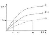
また、制御部80は、駆動側クラッチ板46の接触面46Cと従動側クラッチ板48の接触面48C間の距離(以下、適宜「クラッチ隙間」と記載する)G(図2参照)に応じて電磁石52へ印加する電流を可変する。具体的には、制御部80は、クラッチ隙間Gが大きいときには電磁石52へ印加する電流を増して磁力を強め、クラッチ隙間Gが小さいときには電磁石52へ印加する電流を減らして磁力を弱めて、駆動側クラッチ板46に作用する引き付け力(引力)を一定値に近づけるように制御している。上記制御部80の制御方法の一例を、電磁石52に印加する電流Aと駆動側クラッチ板46に作用する引力Fとの関係を示した図8を用いて説明する。なお、図8の一点鎖線G1、実線G1.5、破線G2は、クラッチ隙間Gが1mm、1.5mm、2mmの場合を示している。図8に示すように、引力fを得る場合、G1、G2、G3ではそれぞれa1、a2、a3の電流値が必要となる。すなわち、駆動側クラッチ板46を従動側クラッチ板48から引き離すときには、クラッチ隙間Gが最も大きいため、電磁石52に印加する電流を増やし、従動側クラッチ板48から駆動側クラッチ板46を引き離した後は、クラッチ隙間Gが小さくなるため、電磁石52に印加する電流を減らすことで、電力消費を抑えることができる。
Further, the
(作用)
次に、本実施形態に係る負圧ポンプ10の作用効果について説明する。
負圧ポンプ10では、コイルスプリング56の押付力(ばね力)によって駆動側クラッチ板46が従動側クラッチ板48に押し付けられて係合することで、駆動軸100の回転が従動軸40に伝達されてポンプ部30が負圧を生成する。
一方、電磁石52でコイルスプリング56のばね力に抗する磁力を発生させた場合には、電磁石52が磁力によって駆動側クラッチ板46を引き付けるため、従動側クラッチ板48から駆動側クラッチ板46が引き離されて駆動側クラッチ板46と従動側クラッチ板48の係合状態が解除される。これにより、ポンプ部30が負圧の生成を停止する。
このように、負圧ポンプ10では、ポンプ部30に対する駆動軸100からの回転の伝達を断続できるため、動力源としてのエンジンのエネルギーロスを低減することができる。これにより、車両の燃費を改善することができる。
(Function)
Next, the effect of the
In the
On the other hand, when the
As described above, in the
また、負圧ポンプ10では、第2筐体32に設けられた張出壁部38によってコイルスプリング56のばね力が作用する従動側クラッチ板48が受け止められる。一方、第1筐体22に設けられた張出壁部28によってコイルスプリング56の一端部56Aが支持される。そして、コイルスプリング56からばね力を受けると共に電磁石52から磁力を受ける駆動側クラッチ板46を駆動軸100の軸方向に移動可能とすることで、駆動軸100にコイルスプリング56のばね力及び電磁石52の磁力に起因するスラスト力が作用するのが抑制される。
さらに、従動側クラッチ板48を従動軸40の軸方向に移動可能としていることから、コイルスプリング56のばね力が従動軸40に作用するのが抑制される。
In the
Further, since the driven side
以上のことから、負圧ポンプ10によれば、エンジンによって回転駆動される駆動軸100にスラスト力が作用するのを抑制すると共に駆動軸100からの回転の伝達を断続することでエンジンのエネルギーロスを低減することができる。
From the above, according to the
また、負圧ポンプ10では、第1筐体22及び第2筐体32をそれぞれ非磁性体としていることから、第1筐体22及び第2筐体32に電磁石52から生じる磁力が伝わらない(磁力が分散しない)ため、電力消費を抑えつつ、駆動側クラッチ板46を従動側クラッチ板48から引き離すことができる。
Further, in the
さらに、負圧ポンプ10では、流路35を通ってポンプ部30から駆動側クラッチ板46の接触面46Cと従動側クラッチ板48の接触面48Cにエンジンオイルが供給されるため、駆動側クラッチ板46と従動側クラッチ板48の各々の接触面46C、48Cの摩耗を抑えられる。また、駆動側クラッチ板46と従動側クラッチ板48の摩擦による発熱も抑えられる。
Further, in the
また、駆動側クラッチ板46及び従動側クラッチ板48を共に同軸方向に移動可能に形成していることから、従動側クラッチ板48に駆動側クラッチ板46をスムーズに係合(再締結)させられる。
Further, since both the drive side
さらに、例えば、電磁石52への通電不良が発生したとしても、負圧ポンプ10自体は作動するため、負圧式ブレーキ倍力装置110を作動させることができる。
Furthermore, for example, even if a failure in energization to the
また、負圧ポンプ10では、エンジンが停止した時に、ポンプ部30内の負圧によってエンジンオイルがポンプ部30内に逆流し留まることがある。その後、エンジン再始動時にポンプ部30内にエンジンオイルが溜まっているとベーン42の回転抵抗が大きくなり、エンジンの始動性が悪化する虞がある。このため、本実施形態では、制御部80が、エンジンを再始動する場合、例えばセルモータに電流を印加させている時に、同時に電磁石52に電流を印加する構成としている。このように電磁石52に電流が印加されると、駆動側クラッチ板46が従動側クラッチ板48から引き離されるため、エンジンの再始動時にポンプ部30が作動せず、エンジンの始動性に影響を与えることがなくなる。そして、制御部80において、エンジン始動後に、例えばセルモータオフ時に、電磁石52への電流の印加を止めることで、回転しているエンジンの動力によって負圧ポンプ10が作動される。また、このとき、電磁石52への電流を徐々に下げるように電流を制御することで、負圧ポンプ10のベーン42がゆっくり回りポンプ部30内のエンジンオイルをポンプ部30の外部に排出することで、ポンプ部30の破損を抑制することもできる。
Further, in the
第1実施形態では、第1筐体22及び第2筐体32を非磁性体で形成する構成としたが、本発明はこの構成に限定されず、第1筐体22のみを非磁性体で形成してもよい。
In the first embodiment, the
第1実施形態の負圧ポンプ10では、図1に示すように、負圧ポンプ10の第1筐体22から駆動軸100を挿入する構成としているが、本発明はこの構成に限定されず、図4、図5に示す変形例の負圧ポンプ11のように、第2筐体32から駆動軸100を挿入する構成としてもよい。具体的には、図4、図5に示すように、負圧ポンプ11では、第1筐体22の張出壁部28で円筒部24を閉塞し、代わりに第2筐体32の蓋39に開口部を形成し、この開口部から駆動軸100を挿入している。
In the
(第2実施形態)
次に、本発明の第2実施形態に係るシリンダヘッドカバー120の一例について図6、図7に従って説明する。
(Second Embodiment)
Next, an example of the
本実施形態のシリンダヘッドカバー120は、エンジンのシリンダヘッドをカバーするのに用いられる。このシリンダヘッドカバー120は、第1実施形態の負圧ポンプ10を備えている。また、シリンダヘッドカバー120の一部は、負圧ポンプ10の第1筐体22を構成(兼用)している。
なお、シリンダヘッドカバー120は、磁性体でも非磁性体でも構わないが、本実施形態では、樹脂で形成されている。
The
The
次に、本実施形態のシリンダヘッドカバー120の作用効果について説明する。
シリンダヘッドカバー120では、負圧ポンプ10を備えることから、エンジンによって回転駆動される駆動軸100にスラスト力が作用するのを抑制すると共に駆動軸100からの回転の伝達を断続することでエンジンのエネルギーロスを低減することができる。これにより、エンジン(車両)の燃費を改善することができる。
また、シリンダヘッドカバー120が第1筐体22を形成することから、例えば、シリンダヘッドカバー120と負圧ポンプ10が別体とされたものと比べて、製造コストを減らすことができる。
Next, the effect of the
Since the
In addition, since the
なお、本発明を特定の実施形態について詳細に説明したが、本発明は係る実施形態に限定されるものではなく、本発明の範囲内にて他の種々の実施形態が可能であることは当業者にとって明らかである。 Although the present invention has been described in detail with respect to specific embodiments, the present invention is not limited to such embodiments, and various other embodiments are possible within the scope of the present invention. It is clear to the contractor.
10 負圧ポンプ
20 筐体
28 張出壁部(第2壁部)
30 ポンプ部
35 流路
38 張出壁部(第1壁部)
40 従動軸
46 駆動側クラッチ板
48 従動側クラッチ板
52 電磁石
56 コイルスプリング(弾性体)
56A 一端部
100 駆動軸
120 シリンダヘッドカバー
DESCRIPTION OF
30
40 driven
56A One
Claims (5)
前記筐体内に形成されると共に従動軸を備え、該従動軸に前記駆動軸の回転が伝達されることで負圧を生成するポンプ部と、
前記駆動軸に取り付けられ、前記駆動軸の軸方向に移動可能でかつ前記駆動軸と一体回転し、磁性を有する駆動側クラッチ板と、
前記従動軸に取り付けられ、前記従動軸と一体回転し、前記駆動側クラッチ板が係合されることによって前記駆動軸からの回転を前記従動軸へ伝達する従動側クラッチ板と、
弾性力により前記駆動側クラッチ板を前記従動側クラッチ板に押し付けて係合させる弾性体と、
前記筐体に固定され、前記弾性体の押付力に抗する磁力を発生させて前記駆動側クラッチ板を前記従動側クラッチ板から引き離し係合状態を解除させる電磁石と、
前記筐体の前記ポンプ部側に設けられ、前記駆動側クラッチ板から前記従動側クラッチ板に伝わる前記弾性体の押付力を前記従動軸を回転自在に支持する第1ベアリングを介して受ける第1壁部と、
前記筐体の前記ポンプ部側と反対側に設けられ、前記弾性体の前記反対側の端部を前記駆動軸を回転自在に支持する第2ベアリングを介して支持する第2壁部と、
を有する負圧ポンプ。 A housing in which a drive shaft that is rotationally driven by a power source is inserted and arranged;
A pump unit that is formed in the housing and includes a driven shaft, and the rotation of the drive shaft is transmitted to the driven shaft to generate a negative pressure;
A drive-side clutch plate attached to the drive shaft, movable in the axial direction of the drive shaft and rotating integrally with the drive shaft, and having magnetism;
A driven-side clutch plate that is attached to the driven shaft, rotates integrally with the driven shaft, and transmits the rotation from the drive shaft to the driven shaft by engaging the drive-side clutch plate;
An elastic body that presses and engages the drive side clutch plate with the driven side clutch plate by an elastic force;
An electromagnet fixed to the housing and generating a magnetic force that resists the pressing force of the elastic body to release the driving clutch plate from the driven clutch plate to release the engaged state;
A first bearing is provided on the pump portion side of the housing and receives a pressing force of the elastic body transmitted from the driving side clutch plate to the driven side clutch plate via a first bearing that rotatably supports the driven shaft . The wall,
A second wall portion provided on the opposite side of the housing to the pump portion side and supporting the opposite end of the elastic body via a second bearing that rotatably supports the drive shaft ;
Having negative pressure pump.
Priority Applications (5)
| Application Number | Priority Date | Filing Date | Title |
|---|---|---|---|
| JP2013157712A JP5799058B2 (en) | 2013-07-30 | 2013-07-30 | Negative pressure pump and cylinder head cover |
| PCT/JP2014/063254 WO2015015868A1 (en) | 2013-07-30 | 2014-05-19 | Negative pressure pump and cylinder head cover |
| EP14831527.8A EP2982864B1 (en) | 2013-07-30 | 2014-05-19 | Negative pressure pump and cylinder head cover |
| CN201480025115.4A CN105190032B (en) | 2013-07-30 | 2014-05-19 | Negative pressure pump and cylinder-head cover |
| US14/888,991 US10233915B2 (en) | 2013-07-30 | 2014-05-19 | Negative pressure pump and cylinder head cover |
Applications Claiming Priority (1)
| Application Number | Priority Date | Filing Date | Title |
|---|---|---|---|
| JP2013157712A JP5799058B2 (en) | 2013-07-30 | 2013-07-30 | Negative pressure pump and cylinder head cover |
Publications (3)
| Publication Number | Publication Date |
|---|---|
| JP2015028305A JP2015028305A (en) | 2015-02-12 |
| JP2015028305A5 JP2015028305A5 (en) | 2015-06-25 |
| JP5799058B2 true JP5799058B2 (en) | 2015-10-21 |
Family
ID=52431414
Family Applications (1)
| Application Number | Title | Priority Date | Filing Date |
|---|---|---|---|
| JP2013157712A Active JP5799058B2 (en) | 2013-07-30 | 2013-07-30 | Negative pressure pump and cylinder head cover |
Country Status (5)
| Country | Link |
|---|---|
| US (1) | US10233915B2 (en) |
| EP (1) | EP2982864B1 (en) |
| JP (1) | JP5799058B2 (en) |
| CN (1) | CN105190032B (en) |
| WO (1) | WO2015015868A1 (en) |
Families Citing this family (7)
| Publication number | Priority date | Publication date | Assignee | Title |
|---|---|---|---|---|
| JP6549418B2 (en) * | 2015-05-28 | 2019-07-24 | 三桜工業株式会社 | Negative pressure pump |
| US10294454B2 (en) | 2016-08-24 | 2019-05-21 | General Electric Company | Methods and kits for cell activation |
| CN106246549B (en) * | 2016-08-31 | 2018-11-30 | 上海肇民动力科技有限公司 | vacuum pump |
| US11529725B2 (en) | 2017-10-20 | 2022-12-20 | Milwaukee Electric Tool Corporation | Power tool including electromagnetic clutch |
| US10981267B2 (en) | 2017-10-26 | 2021-04-20 | Milwaukee Electric Tool Corporation | Kickback control methods for power tools |
| US11641102B2 (en) | 2020-03-10 | 2023-05-02 | Smart Wires Inc. | Modular FACTS devices with external fault current protection within the same impedance injection module |
| FR3131354B1 (en) * | 2021-12-29 | 2024-02-09 | Valeo Embrayages | Actuation assembly and actuator for power train |
Family Cites Families (25)
| Publication number | Priority date | Publication date | Assignee | Title |
|---|---|---|---|---|
| US2230717A (en) * | 1939-10-24 | 1941-02-04 | Gilbert & Barker Mfg Co | Pumping means |
| US4009971A (en) * | 1974-06-07 | 1977-03-01 | Binks Manufacturing Company | Electric motor-driven, double-acting pump having pressure-responsive actuation |
| US4056178A (en) * | 1976-04-28 | 1977-11-01 | Eaton Corporation | Magnetically actuated viscous fluid coupling |
| JPS5690435U (en) * | 1979-12-15 | 1981-07-18 | ||
| JPS5751991A (en) * | 1980-09-12 | 1982-03-27 | Seiko Seiki Co Ltd | Bearing structure for gas compressor |
| US4516918A (en) * | 1982-05-25 | 1985-05-14 | Trw Inc. | Pump assembly |
| GB2162255B (en) * | 1984-03-30 | 1988-02-03 | Grau Girling Limited | Multi-plate clutch in an air compressor |
| EP0284388A3 (en) * | 1987-03-26 | 1989-11-15 | Bendix Limited | Clutch driven compressor assembly |
| US4840543A (en) * | 1988-08-10 | 1989-06-20 | Geberth John Daniel Jun | Clutch apparatus for rapid power source conversion |
| ES2031222T3 (en) * | 1988-12-14 | 1992-12-01 | Christian Mayr Gmbh & Co. Kg | AUTOMATIC RESETTING DEVICE FOR ELECTROMAGNETICALLY OPERATED CLUTCH AND / OR BRAKING GROUPS. |
| JPH0872700A (en) * | 1994-08-31 | 1996-03-19 | Nabco Ltd | Negative pressure generator |
| US5989151A (en) * | 1998-08-11 | 1999-11-23 | Siemens Canada Limited | Hybrid engine cooling system having electric motor with electro-magnetic clutch |
| US6209700B1 (en) * | 1999-09-27 | 2001-04-03 | Tractech Inc. | Electric clutch including resilient disk biasing means |
| DE20221858U1 (en) * | 2002-12-21 | 2008-09-04 | Schaeffler Kg | Internal combustion engine with a device for hydraulic rotation angle adjustment of its camshaft with respect to its crankshaft and with a vacuum pump for a servo consumer, in particular for a brake booster |
| DE102006022472B3 (en) * | 2006-05-13 | 2008-02-07 | Gkn Driveline International Gmbh | Hydrostatic coupling arrangement with gear ring machine |
| US8763734B2 (en) * | 2007-04-05 | 2014-07-01 | Haldex Brake Corporation | Drive through air compressor with cone clutch |
| JP5359204B2 (en) * | 2008-11-10 | 2013-12-04 | 日産自動車株式会社 | Vacuum pump structure |
| JP2011220326A (en) * | 2010-03-25 | 2011-11-04 | Aisin Seiki Co Ltd | Water pump for vehicle |
| JP5447149B2 (en) * | 2010-04-27 | 2014-03-19 | 大豊工業株式会社 | Vane pump |
| WO2012045151A1 (en) * | 2010-10-04 | 2012-04-12 | Litens Automotive Partnership | Driven component with clutch for selective operation of component |
| JP5776172B2 (en) * | 2010-12-09 | 2015-09-09 | スズキ株式会社 | Vacuum pump mounting structure |
| JP5482706B2 (en) * | 2011-03-28 | 2014-05-07 | 株式会社豊田自動織機 | Compressor with transmission |
| WO2012142023A2 (en) * | 2011-04-13 | 2012-10-18 | Borgwarner Inc. | Compression spring members |
| JP5716615B2 (en) * | 2011-09-08 | 2015-05-13 | トヨタ自動車株式会社 | Water pump |
| JP5890186B2 (en) | 2012-01-27 | 2016-03-22 | 京セラ株式会社 | Portable terminal, lock state control program, and lock state control method |
-
2013
- 2013-07-30 JP JP2013157712A patent/JP5799058B2/en active Active
-
2014
- 2014-05-19 EP EP14831527.8A patent/EP2982864B1/en not_active Not-in-force
- 2014-05-19 US US14/888,991 patent/US10233915B2/en active Active
- 2014-05-19 CN CN201480025115.4A patent/CN105190032B/en active Active
- 2014-05-19 WO PCT/JP2014/063254 patent/WO2015015868A1/en active Application Filing
Also Published As
| Publication number | Publication date |
|---|---|
| CN105190032A (en) | 2015-12-23 |
| EP2982864A1 (en) | 2016-02-10 |
| WO2015015868A1 (en) | 2015-02-05 |
| EP2982864A4 (en) | 2016-05-18 |
| US10233915B2 (en) | 2019-03-19 |
| EP2982864B1 (en) | 2017-08-09 |
| CN105190032B (en) | 2017-12-29 |
| JP2015028305A (en) | 2015-02-12 |
| US20160084244A1 (en) | 2016-03-24 |
Similar Documents
| Publication | Publication Date | Title |
|---|---|---|
| JP5799058B2 (en) | Negative pressure pump and cylinder head cover | |
| JP2015028305A5 (en) | ||
| JP7016805B6 (en) | Morning sickness valve system for viscous clutches | |
| JP6324137B2 (en) | Continuously variable transmission for vehicles with seal mechanism | |
| US20080073170A1 (en) | Power transmission device | |
| JP5390886B2 (en) | Power transmission device | |
| US10711684B2 (en) | Fluid fan clutch | |
| JP2010112337A (en) | Vacuum pump structure | |
| JP6849111B2 (en) | Selectable clutch | |
| US11499594B2 (en) | Magnetorheological fluid clutch apparatus with low permeability drums | |
| JP5784800B1 (en) | Negative pressure pump drive control method | |
| JP6549418B2 (en) | Negative pressure pump | |
| JP4199105B2 (en) | Electromagnetic brake cooling structure of phase variable device in automotive engine | |
| JP5256814B2 (en) | Variable flywheel | |
| JP6794745B2 (en) | Fluid pressure pump | |
| JP2015169233A (en) | electromagnetic clutch | |
| JP2014066180A (en) | Electric pump | |
| JP6244239B2 (en) | Continuously variable transmission for vehicles with seal mechanism | |
| JP2009162326A (en) | Power transmission device | |
| JP2011226499A (en) | Electromagnetic engagement device | |
| JP2009228766A (en) | Flywheel structure | |
| JP2017166594A (en) | Frictional engagement device | |
| JP2016089645A (en) | Water pump | |
| JP2009192052A (en) | Power transmission device | |
| JP2013221540A (en) | Driving force transmission device |
Legal Events
| Date | Code | Title | Description |
|---|---|---|---|
| A521 | Request for written amendment filed |
Free format text: JAPANESE INTERMEDIATE CODE: A523 Effective date: 20150424 |
|
| A621 | Written request for application examination |
Free format text: JAPANESE INTERMEDIATE CODE: A621 Effective date: 20150424 |
|
| A871 | Explanation of circumstances concerning accelerated examination |
Free format text: JAPANESE INTERMEDIATE CODE: A871 Effective date: 20150424 |
|
| A975 | Report on accelerated examination |
Free format text: JAPANESE INTERMEDIATE CODE: A971005 Effective date: 20150527 |
|
| A131 | Notification of reasons for refusal |
Free format text: JAPANESE INTERMEDIATE CODE: A131 Effective date: 20150602 |
|
| A521 | Request for written amendment filed |
Free format text: JAPANESE INTERMEDIATE CODE: A523 Effective date: 20150729 |
|
| TRDD | Decision of grant or rejection written | ||
| A01 | Written decision to grant a patent or to grant a registration (utility model) |
Free format text: JAPANESE INTERMEDIATE CODE: A01 Effective date: 20150818 |
|
| A61 | First payment of annual fees (during grant procedure) |
Free format text: JAPANESE INTERMEDIATE CODE: A61 Effective date: 20150824 |
|
| R150 | Certificate of patent or registration of utility model |
Ref document number: 5799058 Country of ref document: JP Free format text: JAPANESE INTERMEDIATE CODE: R150 |
|
| R250 | Receipt of annual fees |
Free format text: JAPANESE INTERMEDIATE CODE: R250 |
|
| R250 | Receipt of annual fees |
Free format text: JAPANESE INTERMEDIATE CODE: R250 |
|
| R250 | Receipt of annual fees |
Free format text: JAPANESE INTERMEDIATE CODE: R250 |
|
| R250 | Receipt of annual fees |
Free format text: JAPANESE INTERMEDIATE CODE: R250 |
|
| R250 | Receipt of annual fees |
Free format text: JAPANESE INTERMEDIATE CODE: R250 |