JP5716615B2 - Water pump - Google Patents

Water pump Download PDF

Info

Publication number
JP5716615B2
JP5716615B2 JP2011196020A JP2011196020A JP5716615B2 JP 5716615 B2 JP5716615 B2 JP 5716615B2 JP 2011196020 A JP2011196020 A JP 2011196020A JP 2011196020 A JP2011196020 A JP 2011196020A JP 5716615 B2 JP5716615 B2 JP 5716615B2
Authority
JP
Japan
Prior art keywords
power transmission
pulley
driven
slide plate
water pump
Prior art date
Legal status (The legal status is an assumption and is not a legal conclusion. Google has not performed a legal analysis and makes no representation as to the accuracy of the status listed.)
Expired - Fee Related
Application number
JP2011196020A
Other languages
Japanese (ja)
Other versions
JP2013057293A (en
Inventor
砂田 洋尚
洋尚 砂田
Current Assignee (The listed assignees may be inaccurate. Google has not performed a legal analysis and makes no representation or warranty as to the accuracy of the list.)
Toyota Motor Corp
Original Assignee
Toyota Motor Corp
Priority date (The priority date is an assumption and is not a legal conclusion. Google has not performed a legal analysis and makes no representation as to the accuracy of the date listed.)
Filing date
Publication date
Application filed by Toyota Motor Corp filed Critical Toyota Motor Corp
Priority to JP2011196020A priority Critical patent/JP5716615B2/en
Publication of JP2013057293A publication Critical patent/JP2013057293A/en
Application granted granted Critical
Publication of JP5716615B2 publication Critical patent/JP5716615B2/en
Expired - Fee Related legal-status Critical Current
Anticipated expiration legal-status Critical

Links

Images

Landscapes

  • Structures Of Non-Positive Displacement Pumps (AREA)

Description

本発明はウォータポンプに関する。   The present invention relates to a water pump.

コイル通電時に駆動側回転体から従動側回転体への動力伝達を切断し、コイル非通電時に駆動側回転体から従動側回転体への動力伝達を可能にする無励磁作動型の動力伝達機構を備えるウォータポンプが知られている。かかるウォータポンプによれば、ウォータポンプ作動中に常時電力を消費しないで済むことから、消費電力を大幅に削減できる。かかるウォータポンプは例えば特許文献1や2で開示されている。   A non-excitation operation type power transmission mechanism that cuts power transmission from the drive side rotator to the driven side rotator when the coil is energized and enables power transmission from the drive side rotator to the driven side rotator when the coil is not energized. A water pump is known. According to such a water pump, it is not necessary to always consume power during the operation of the water pump, so that power consumption can be greatly reduced. Such a water pump is disclosed in Patent Documents 1 and 2, for example.

2010−203406号公報No. 2010-203406 2010−265837号公報2010-265837

無励磁作動型の動力伝達機構を備えるウォータポンプでは、例えば駆動側回転体と従動側回転体とを圧着することで、動力の伝達に必要な係合状態を確立する圧着式の動力伝達機構を用いることができる。ところがこの場合、係合状態を確保するにあたって例えば駆動側回転体と従動側回転体の係合面それぞれに相応の係合面積を確保する必要が生じる結果、動力伝達機構が大型化する虞がある。   In a water pump including a non-excitation operation type power transmission mechanism, for example, a crimp type power transmission mechanism that establishes an engagement state necessary for power transmission by crimping a driving side rotating body and a driven side rotating body. Can be used. However, in this case, in order to ensure the engagement state, for example, it is necessary to secure a corresponding engagement area on each of the engagement surfaces of the driving side rotating body and the driven side rotating body. As a result, the power transmission mechanism may be increased in size. .

これに対し、例えば係合する駆動側回転体、従動側回転体間で大きな摩擦力を得られる構造を採用することで、動力伝達機構の大型化を抑制しつつ、係合状態を確保することも考えられる。ところがこの場合には構造が複雑になる結果、コスト面で不利になる虞がある。また、例えば駆動側回転体と従動側回転体の圧着力を大きくすることで、動力伝達機構の大型化を抑制しつつ、係合状態を確保することも考えられる。ところがこの場合には、動力伝達の切断に必要な力を発生させるコイルの消費電力が大きくなる虞がある。   On the other hand, for example, by adopting a structure that can obtain a large frictional force between the driving-side rotating body and the driven-side rotating body to be engaged, it is possible to ensure the engaged state while suppressing an increase in the size of the power transmission mechanism. Is also possible. In this case, however, the structure becomes complicated, which may be disadvantageous in terms of cost. Further, for example, it is conceivable to secure the engaged state while suppressing the enlargement of the power transmission mechanism by increasing the pressure-bonding force between the driving side rotating body and the driven side rotating body. However, in this case, there is a possibility that the power consumption of the coil that generates the force necessary for cutting off the power transmission becomes large.

本発明は上記課題に鑑み、無励磁作動型の動力伝達機構を備える場合にコンパクトで簡素な構造を実現するとともに、消費電力の更なる低減を図ることが可能なウォータポンプを提供することを目的とする。   The present invention has been made in view of the above problems, and an object thereof is to provide a water pump capable of realizing a compact and simple structure and further reducing power consumption when a non-excitation operation type power transmission mechanism is provided. And

本発明は駆動側回転体と、前記駆動側回転体から動力が伝達されるスライド式の従動側回転体と、ボディに設けられ、通電時に前記駆動側回転体から離間して前記ボディに近接する方向に前記従動側回転体を駆動するコイルと、前記ボディと従動側回転体との間に位置し、かつ前記従動側回転体とともに回転し、前記駆動側回転体に接近する方向に前記従動側回転体を駆動する駆動部と、を備え、前記コイルの通電時に前記駆動側回転体前記従動側回転体との間の動力伝達を切断し、前記コイルの非通電時に前記駆動側回転体前記従動側回転体との間の動力伝達を可能にする噛み合い式の動力伝達機構を備えるウォータポンプである。 The present invention is provided in a drive-side rotator, a slide-type driven-side rotator to which power is transmitted from the drive-side rotator, and the body, and is separated from the drive-side rotator and close to the body when energized. A coil that drives the driven-side rotator in a direction , and is positioned between the body and the driven-side rotator, rotates with the driven-side rotator, and approaches the drive-side rotator in the direction of the driven side and a driving unit for driving the rotating body, cutting the power transmission between the driving side rotational member at the time of energization of the coil and the driven side rotational member, and the driving side rotational member at the time of non-energization of the coil a water pump with a meshing type power transmission mechanism that permits power transmission between the driven side rotational member.

本発明は前記動力伝達機構が前記駆動側回転体、前記従動側回転体間に介在するように設けられ、前記駆動側回転体、前記従動側回転体間の噛み合いを仲介するボール部を備える構成とすることができる。   The present invention is configured such that the power transmission mechanism is provided so as to be interposed between the driving side rotating body and the driven side rotating body, and includes a ball portion that mediates the engagement between the driving side rotating body and the driven side rotating body. It can be.

本発明によれば、無励磁作動型の動力伝達機構を備える場合にコンパクトで簡素な構造を実現するとともに、消費電力の更なる低減を図ることができる。   According to the present invention, a compact and simple structure can be realized when a non-excitation operation type power transmission mechanism is provided, and further reduction of power consumption can be achieved.

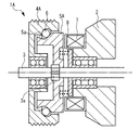
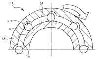
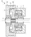
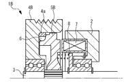
実施例1のウォータポンプの要部を示す図である。It is a figure which shows the principal part of the water pump of Example 1. FIG. 非通電時の第1の動力伝達機構の水平断面図である。It is a horizontal sectional view of the 1st power transmission mechanism at the time of non-energization. 非通電時の第1の動力伝達機構の垂直断面図である。It is a vertical sectional view of the first power transmission mechanism when not energized. 通電時の第1の動力伝達機構の水平断面図である。It is a horizontal sectional view of the 1st power transmission mechanism at the time of energization. 通電時の第1の動力伝達機構の垂直断面図である。It is a vertical sectional view of the first power transmission mechanism during energization. 実施例2のウォータポンプの要部を示す図である。It is a figure which shows the principal part of the water pump of Example 2. FIG. 非通電時の第2の動力伝達機構の水平断面図である。It is a horizontal sectional view of the 2nd power transmission mechanism at the time of non-energization. 非通電時の第2の動力伝達機構の垂直断面図である。It is a vertical sectional view of the second power transmission mechanism when not energized. 通電時の第2の動力伝達機構の水平断面図である。It is a horizontal sectional view of the 2nd power transmission mechanism at the time of energization. 通電時の第2の動力伝達機構の垂直断面図である。It is a vertical sectional view of the second power transmission mechanism during energization. 非通電時の第3の動力伝達機構の水平断面図である。It is a horizontal sectional view of the 3rd power transmission mechanism at the time of non-energization. 非通電時の第3の動力伝達機構の垂直断面図である。It is a vertical sectional view of the 3rd power transmission mechanism at the time of non-energization. 通電時の第3の動力伝達機構の水平断面図である。It is a horizontal sectional view of the 3rd power transmission mechanism at the time of energization. 通電時の第3の動力伝達機構の垂直断面図である。It is a vertical sectional view of the third power transmission mechanism during energization. 駆動側ボール受け部の説明図である。It is explanatory drawing of a drive side ball | bowl receiving part. 第1の変形例の水平断面図である。It is a horizontal sectional view of the 1st modification. 第1の変形例の垂直断面図である。It is a vertical sectional view of the first modification. 第2の変形例の水平断面図である。It is a horizontal sectional view of the 2nd modification.

図面を用いて、本発明の実施例について説明する。   Embodiments of the present invention will be described with reference to the drawings.

図1はウォータポンプ1Aの要部を示す図である。ウォータポンプ1Aはボディ2とシャフト3とプーリ4Aとスライドプレート5Aとボール6とコイル7とスプリング8とを備えている。ボディ2は筐体部材であり、ボディ2にはベアリングを介してシャフト3が設けられている。シャフト3は駆動軸であり、ボディ2から突出した部分にスプライン軸部3aを備えている。   FIG. 1 is a view showing a main part of the water pump 1A. The water pump 1A includes a body 2, a shaft 3, a pulley 4A, a slide plate 5A, a ball 6, a coil 7, and a spring 8. The body 2 is a casing member, and the body 2 is provided with a shaft 3 via a bearing. The shaft 3 is a drive shaft and includes a spline shaft portion 3 a at a portion protruding from the body 2.

プーリ4Aは駆動側回転体であり、ベアリングを介してシャフト3に設けられている。プーリ4Aはシャフト3のうち、スプライン軸部3aよりも先端側の部分に設けられている。プーリ4Aにはエンジンの駆動力を伝達可能なベルトを外周部に巻き掛けることで、エンジンの駆動力を伝達することができる。この点、ウォータポンプ1Aはエンジンの冷却水を圧送するウォータポンプとなっている。   The pulley 4A is a driving side rotating body, and is provided on the shaft 3 via a bearing. The pulley 4A is provided in a portion of the shaft 3 on the tip side of the spline shaft portion 3a. The driving force of the engine can be transmitted to the pulley 4A by winding a belt capable of transmitting the driving force of the engine around the outer periphery. In this regard, the water pump 1A is a water pump that pumps engine cooling water.

プーリ4Aは有底円筒状の形状を有している。具体的にはプーリ4Aはボディ2側で円筒状に開口するとともに、ボディ2の反対側で有底円筒形状の底壁部をなす壁部を有している。そしてこれにより、外周部と対をなすように設けられた内周部を有している。さらにプーリ4Aはボディ2の反対側の壁部中央に開口するとともに、ボディ2側に向かって延伸する円筒状のベアリング保持部を内周部よりも内側の部分に有している。   The pulley 4A has a bottomed cylindrical shape. Specifically, the pulley 4 </ b> A opens in a cylindrical shape on the body 2 side and has a wall portion that forms a bottom wall portion having a bottomed cylindrical shape on the opposite side of the body 2. And it has the inner peripheral part provided so that it might make a pair with an outer peripheral part by this. Further, the pulley 4A has an opening in the center of the wall portion on the opposite side of the body 2, and has a cylindrical bearing holding portion extending toward the body 2 side in a portion inside the inner peripheral portion.

スライドプレート5Aはスライド式の従動側回転体であり、スライドプレート5Aにはプーリ4Aから動力が伝達される。スライドプレート5Aはスプライン軸部3aに設けられている。この点、スライドプレート5Aは中央にスプライン穴を有しており、このスプライン穴を介してスプライン軸部3aに設けられている。そしてこれにより、軸方向に沿ってスライド可能に設けられるとともに、シャフト3と一体回転可能に設けられている。スプラインには例えば軸方向に沿って歯が設けられたスプラインのほか、ヘルカルスプラインなど適宜のスプラインが適用されてよい。   The slide plate 5A is a slide-type driven rotating body, and power is transmitted from the pulley 4A to the slide plate 5A. The slide plate 5A is provided on the spline shaft portion 3a. In this regard, the slide plate 5A has a spline hole in the center, and is provided on the spline shaft portion 3a via the spline hole. And thereby, it is provided so that a slide is possible along an axial direction, and it is provided so that integral rotation with the shaft 3 is possible. For example, in addition to a spline provided with teeth along the axial direction, an appropriate spline such as a helical spline may be applied to the spline.

スライドプレート5Aは有底円筒状の形状を有している。具体的にはスライドプレート5Aはプーリ4A側で円筒状に開口するとともに、ボディ2側で有底円筒形状の底壁部をなす壁部を有している。スライドプレート5Aはプーリ4Aに挿入可能に設けられている。この点、スライドプレート5Aの外周部はプーリ4Aに挿入された状態で、プーリ4Aの内周部と隙間を有して対向するように設けられている。スライドプレート5Aの外周部には凹曲面状の壁面を有する溝部5aが設けられている。溝部5aは一周に亘って帯び状に設けられている。   The slide plate 5A has a bottomed cylindrical shape. Specifically, the slide plate 5A has a cylindrical opening on the pulley 4A side and a wall portion forming a bottomed cylindrical bottom wall portion on the body 2 side. The slide plate 5A is provided so as to be insertable into the pulley 4A. In this regard, the outer peripheral portion of the slide plate 5A is provided so as to face the inner peripheral portion of the pulley 4A with a gap in a state of being inserted into the pulley 4A. A groove 5a having a concave curved wall surface is provided on the outer periphery of the slide plate 5A. The groove 5a is provided in a strip shape over the entire circumference.

ボール6はプーリ4A、スライドプレート5A間に介在するように設けられている。ボール6は複数(ここでは8つ)設けられている。ボール6の材質は例えば炭素鋼である。コイル7はボディ2に設けられている。コイル7はスライドプレート5Aに対向する位置に設けられており、通電時にプーリ4Aから離間する方向に磁性体からなるスライドプレート5Aを駆動する。   The ball 6 is provided so as to be interposed between the pulley 4A and the slide plate 5A. A plurality (eight here) of balls 6 are provided. The material of the ball 6 is, for example, carbon steel. The coil 7 is provided on the body 2. The coil 7 is provided at a position facing the slide plate 5A, and drives the slide plate 5A made of a magnetic material in a direction away from the pulley 4A when energized.

スプリング8はボディ2、スライドプレート5A間に設けられている。スプリング8は周方向に沿って均等に複数設けられている。スプリング8それぞれはスライドプレート5Aとともに回転できるように設けられている。スプリング8それぞれが摺動する部分にはスラストベアリングを設けることができる。スプリング8それぞれはプーリ4Aに接近する方向にスライドプレート5Aを駆動する。複数のスプリング8は駆動部に相当する。駆動部は例えば永久磁石であってもよい。   The spring 8 is provided between the body 2 and the slide plate 5A. A plurality of springs 8 are equally provided along the circumferential direction. Each of the springs 8 is provided so as to be able to rotate together with the slide plate 5A. A thrust bearing can be provided in a portion where each spring 8 slides. Each of the springs 8 drives the slide plate 5A in a direction approaching the pulley 4A. The plurality of springs 8 correspond to drive units. The driving unit may be a permanent magnet, for example.

図2はコイル7非通電時の第1の動力伝達機構の水平断面図である。図3はコイル7非通電時の第1の動力伝達機構の垂直断面図である。ウォータポンプ1Aは駆動側ボール受け部R11それぞれと従動側ボール受け部R21それぞれと複数のボール6とを有して構成される噛み合い式の動力伝達機構である第1の動力伝達機構を備えている。   FIG. 2 is a horizontal sectional view of the first power transmission mechanism when the coil 7 is not energized. FIG. 3 is a vertical sectional view of the first power transmission mechanism when the coil 7 is not energized. The water pump 1 </ b> A includes a first power transmission mechanism that is a meshing power transmission mechanism that includes each of the driving side ball receiving portions R <b> 11, the driven side ball receiving portions R <b> 21, and the plurality of balls 6. .

駆動側ボール受け部R11はプーリ4Aの内周部に設けられている。この点、プーリ4Aの内周部はボディ2側の部分よりも反対側の部分のほうが、径が小さくなるように設けられている。そして、駆動側ボール受け部R11はプーリ4Aの内周部のうち、ボディ2側の部分とは反対側の縮径した部分に隣接してボディ2側の部分に部分球状の空間を形成するように設けられている。駆動側ボール受け部R11が形成する部分球状の空間の径はボール6の径よりも若干大きめに設定されている。駆動側ボール受け部R11は周方向に沿って均等に複数(ここでは8つ)設けられている。この点、ボール6の数と駆動側ボール受け部R11の数とは互いに等しくなっている。   The driving side ball receiving portion R11 is provided on the inner peripheral portion of the pulley 4A. In this regard, the inner peripheral portion of the pulley 4A is provided so that the diameter of the portion on the opposite side is smaller than the portion on the body 2 side. The driving-side ball receiving portion R11 forms a partial spherical space in the portion on the body 2 side adjacent to the reduced diameter portion on the opposite side to the portion on the body 2 side in the inner peripheral portion of the pulley 4A. Is provided. The diameter of the partially spherical space formed by the driving side ball receiving portion R11 is set slightly larger than the diameter of the ball 6. A plurality (eight in this case) of driving side ball receiving portions R11 are equally provided along the circumferential direction. In this respect, the number of balls 6 and the number of driving side ball receiving portions R11 are equal to each other.

従動側ボール受け部R21は溝部5aに設けられている。この点、溝部5aは具体的には駆動側ボール受け部R11との間で径方向に沿った最深部同士の間隔がボール6の径よりも大きくなるように設けられている。また、ボディ2側とその反対側とで径が異なるプーリ4Aの内周部に対応させて、最深部よりもプーリ4A側のスロープ部のほうがボディ2側のスロープ部よりも径方向の高さが低くなるように設けられている。この点、スライドプレート5Aの外周部のうち、溝部5aよりもボディ2側の部分の径はプーリ4Aの内周部のうち、ボディ2側の部分の径よりも小さく、且つボディ2側とは反対側の部分の径よりも大きく設定されている。溝部5aはコイル7通電時に最深部が駆動側ボール受け部R11と対向するように設けられている。   The driven ball receiving portion R21 is provided in the groove portion 5a. In this respect, the groove portion 5a is specifically provided so that the distance between the deepest portions along the radial direction between the driving side ball receiving portion R11 and the diameter of the ball 6 is larger. Also, the slope portion on the pulley 4A side is higher in the radial direction than the slope portion on the body 2 side than the deepest portion in correspondence with the inner peripheral portion of the pulley 4A having different diameters on the body 2 side and the opposite side. Is provided to be low. In this respect, the diameter of the portion of the outer peripheral portion of the slide plate 5A closer to the body 2 than the groove portion 5a is smaller than the diameter of the inner peripheral portion of the pulley 4A to the portion of the body 2 side. It is set larger than the diameter of the opposite part. The groove 5a is provided so that the deepest part faces the driving side ball receiving part R11 when the coil 7 is energized.

従動側ボール受け部R21は具体的には溝部5aのうち、コイル7非通電時に軸方向において駆動側ボール受け部R11と位置が重なる部分に設けられている。従動側ボール受け部R21のうち、プーリ4Aの回転方向において後方となる部分には、ボール受け面が設けられている。このボール受け面は軸方向に沿った移動でボール6との係合状態が解除できるように設けられており、ボール6に合わせて窪んだ曲面形状を有している。従動側ボール受け部R21は周方向に沿って複数(ここでは8つ)設けられている。この点、ボール6の数と従動側ボール受け部R21の数とは互いに等しくなっている。   Specifically, the driven-side ball receiving portion R21 is provided in a portion of the groove portion 5a that overlaps with the driving-side ball receiving portion R11 in the axial direction when the coil 7 is not energized. A ball receiving surface is provided in a portion of the driven side ball receiving portion R21 that is rearward in the rotation direction of the pulley 4A. The ball receiving surface is provided so that the engaged state with the ball 6 can be released by movement along the axial direction, and has a curved surface shape that is recessed in accordance with the ball 6. A plurality (eight in this case) of driven side ball receiving portions R21 are provided along the circumferential direction. In this respect, the number of balls 6 and the number of driven ball receiving portions R21 are equal to each other.

ボール6は具体的には径方向において駆動側ボール受け部R11と溝部5aとの間それぞれに介在するように設けられている。そしてこの状態で、対応する駆動側ボール受け部R11に保持されるように設けられている。このように設けられた複数のボール6はシャフト3に対して同心円状に配置されている。複数のボール6の数は作用する力の関係上、例えば4つ以上であることが好ましい。   Specifically, the balls 6 are provided so as to be interposed between the driving side ball receiving portion R11 and the groove portion 5a in the radial direction. And in this state, it is provided so that it may be hold | maintained to corresponding drive side ball receiving part R11. The plurality of balls 6 thus provided are arranged concentrically with respect to the shaft 3. The number of the plurality of balls 6 is preferably four or more, for example, in view of the acting force.

コイル7を非通電にした場合の第1の動力伝達機構の動作は次の通りである。すなわち、コイル7を非通電にした場合にはスプリング8それぞれがスライドプレート5Aをプーリ4A側に駆動する。結果、従動側ボール受け部R21が軸方向においてボール6と重なる位置に配置される。また、ボール6それぞれが溝部5aのうち、ボディ2側のスロープ部によって径方向外側に位置する駆動側ボール受け部R11に押し付けられる。   The operation of the first power transmission mechanism when the coil 7 is not energized is as follows. That is, when the coil 7 is de-energized, each spring 8 drives the slide plate 5A toward the pulley 4A. As a result, the driven side ball receiving portion R21 is disposed at a position overlapping the ball 6 in the axial direction. Further, each ball 6 is pressed against the driving side ball receiving portion R11 located on the outer side in the radial direction by the slope portion on the body 2 side in the groove portion 5a.

そしてこの状態で、ボール6それぞれはプーリ4Aとともに回転し、対応する従動側ボール受け部R21それぞれに到達する。結果、第1の動力伝達機構が係合状態となる。このとき、ボール6それぞれはプーリ4A、スライドプレート5A間の噛み合いを仲介することで、コイル7の非通電時にプーリ4A、スライドプレート5A間の動力伝達を可能にする。この点、複数のボール6はボール部に相当している。   In this state, each of the balls 6 rotates together with the pulley 4A and reaches each corresponding driven ball receiving portion R21. As a result, the first power transmission mechanism is engaged. At this time, each ball 6 mediates meshing between the pulley 4A and the slide plate 5A, thereby enabling power transmission between the pulley 4A and the slide plate 5A when the coil 7 is not energized. In this regard, the plurality of balls 6 correspond to ball portions.

図4はコイル7通電時の第1の動力伝達機構の水平断面図である。図5はコイル7通電時の第1の動力伝達機構の垂直断面図である。コイル7に通電した場合の第1の動力伝達機構の動作は次の通りである。すなわち、コイル7に通電した場合にはコイル7がスプリング8の付勢力に抗してスライドプレート5Aをボディ2側に駆動する。結果、従動側ボール受け部R21が軸方向においてボール6と重なり合わない位置に配置される。また、溝部5aの最深部が駆動側ボール受け部R11に対向する位置に配置される。そしてこれにより、第1の動力伝達機構の係合状態が解除される。結果、ボール6それぞれを介したプーリ4A、スライドプレート5A間の動力伝達が切断される。   FIG. 4 is a horizontal sectional view of the first power transmission mechanism when the coil 7 is energized. FIG. 5 is a vertical sectional view of the first power transmission mechanism when the coil 7 is energized. The operation of the first power transmission mechanism when the coil 7 is energized is as follows. That is, when the coil 7 is energized, the coil 7 drives the slide plate 5 </ b> A toward the body 2 against the urging force of the spring 8. As a result, the driven-side ball receiving portion R21 is disposed at a position that does not overlap the ball 6 in the axial direction. Further, the deepest portion of the groove 5a is disposed at a position facing the driving side ball receiving portion R11. Thereby, the engaged state of the first power transmission mechanism is released. As a result, power transmission between the pulley 4A and the slide plate 5A via the balls 6 is cut off.

次にウォータポンプ1Aの作用効果について説明する。ウォータポンプ1Aでは、噛み合い式の動力伝達機構である第1の動力伝達機構がコイル7の通電時にプーリ4A、スライドプレート5A間の動力伝達を切断し、コイル7の非通電時にプーリ4A、スライドプレート5A間の動力伝達を可能にする。   Next, the effect of the water pump 1A will be described. In the water pump 1A, the first power transmission mechanism, which is a meshing power transmission mechanism, cuts off the power transmission between the pulley 4A and the slide plate 5A when the coil 7 is energized, and the pulley 4A and the slide plate when the coil 7 is not energized. Allows power transmission between 5A.

この点、噛み合い式の動力伝達機構によれば、噛み合いによって係合状態を維持することから、例えば圧着式の動力伝達機構に対して生じる係合面積を増大させるための大型化や、係合面積を増大させるための構造変更といった要請が特段生じない。また、噛み合い式の動力伝達機構によれば、係合状態を確保するための圧着力を特段必要としない分、スプリング8の力も軽減できる。結果、通電時に要するコイル7の駆動力を低減できる分、消費電力の低減を図ることもできる。   In this regard, according to the meshing type power transmission mechanism, the engagement state is maintained by the meshing, so that, for example, an increase in the size of the engagement to increase the engagement area generated for the crimping type power transmission mechanism, and the engagement area There is no particular request for structural changes to increase Further, according to the meshing type power transmission mechanism, the force of the spring 8 can be reduced by the amount that does not require a special crimping force for securing the engaged state. As a result, it is possible to reduce power consumption by the amount that the driving force of the coil 7 required for energization can be reduced.

このため、ウォータポンプ1Aは無励磁作動型の動力伝達機構を備える場合にコンパクトで簡素な構造を実現するとともに、消費電力の更なる低減を図ることができる。この点、ウォータポンプ1Aは消費電力の低減に応じたコイル7のコンパクト化を図ることができる点でもコンパクトな構造を実現できる。   Therefore, when the water pump 1A includes a non-excitation operation type power transmission mechanism, the water pump 1A can achieve a compact and simple structure and can further reduce power consumption. In this respect, the water pump 1A can also realize a compact structure in that the coil 7 can be made compact in accordance with the reduction in power consumption.

ウォータポンプ1Aでは、ボール6それぞれがプーリ4A、スライドプレート5A間の噛み合いを仲介する。この点、ウォータポンプ1Aはボール6それぞれを噛み合いの仲介に用いることで、係合時にプーリ4Aとスライドプレート5Aとをくさびの効果で機械的にロックすることもできる。そしてこれにより、例えば回転変動によって動力の伝達が寸断される事態が発生することも防止できる。また、ウォータポンプ1Aはボール6それぞれを噛み合いの仲介に用いることで、係合時に加わる衝撃に対する強度も容易に確保できる。   In the water pump 1A, each ball 6 mediates the engagement between the pulley 4A and the slide plate 5A. In this respect, the water pump 1A can also mechanically lock the pulley 4A and the slide plate 5A by the effect of a wedge by using the balls 6 for mediation of engagement. As a result, it is also possible to prevent a situation in which transmission of power is interrupted due to, for example, rotational fluctuation. Further, the water pump 1A can easily secure the strength against the impact applied at the time of engagement by using each of the balls 6 for mediation of engagement.

ウォータポンプ1Aはボール6それぞれでプーリ4A、スライドプレート5A間の噛み合いを仲介するにあたって、噛み合い式の動力伝達機構がプーリ4Aに設けられた駆動側ボール受け部R11と、スライドプレート5Aに設けられた従動側ボール受け部R21とをボール6毎に備えるとともに、従動側ボール受け部R21が軸方向に沿った移動で対応するボール6との係合状態が解除できるように設けられたボール受け面を備える構成となっている。このため、ウォータポンプ1Aは係合解除時に係合状態が持続するストロークを短く設定することもできる。そしてこれにより、消費電力を低減することもできる。   When the water pump 1A mediates the engagement between the pulley 4A and the slide plate 5A with each of the balls 6, an engagement type power transmission mechanism is provided on the drive side ball receiving portion R11 provided on the pulley 4A and the slide plate 5A. Each ball 6 has a driven ball receiving portion R21 and a ball receiving surface provided so that the driven side ball receiving portion R21 can be released from the engaged state with the corresponding ball 6 by movement along the axial direction. It is configured to be equipped. For this reason, the water pump 1A can also set a short stroke for maintaining the engaged state when the engagement is released. As a result, power consumption can also be reduced.

ウォータポンプ1Aはボール6それぞれでプーリ4A、スライドプレート5A間の噛み合いを仲介するにあたって、スライドプレート5Aが係合時にボール6それぞれを径方向外側に位置する駆動側ボール受け部R11に押し付けるように作用するスロープ部を備えている。   When the water pump 1A mediates the engagement between the pulley 4A and the slide plate 5A with each of the balls 6, the water pump 1A acts so as to press the balls 6 against the driving side ball receiving portion R11 positioned radially outward when the slide plate 5A is engaged. It has a slope part.

このため、ウォータポンプ1Aは係合時にスライドプレート5Aの回転をプーリ4Aの回転に同期させるようにして、係合時に加わる衝撃を緩和することもできる。また、ウォータポンプ1Aはかかるスロープ部によってボール6それぞれにくさびの効果を発揮させることもできる。そしてこれにより、ボール6それぞれに遠心力が作用しても、プーリ4A、スライドプレート5A間の結合にゆるみが発生しないようにすることもできる。   For this reason, the water pump 1A can also relieve the impact applied at the time of engagement by synchronizing the rotation of the slide plate 5A with the rotation of the pulley 4A at the time of engagement. Further, the water pump 1A can also exert a wedge effect on each of the balls 6 by the slope portion. As a result, even if a centrifugal force acts on each of the balls 6, it is possible to prevent loosening of the coupling between the pulley 4A and the slide plate 5A.

なお、噛み合い式の動力伝達機構の適用対象としては、例えばエンジンで駆動されるエアコン用コンプレッサも考えられる。ところが、エアコン用コンプレッサの駆動トルクはウォータポンプの駆動トルクと比較して一般に大きくなっている。この点、噛み合い式の動力伝達機構は係合時に加わる衝撃の大きさに照らして、ウォータポンプとの相性がよい。また、噛み合い式の動力伝達機構である第1の動力伝達機構を備えるウォータポンプ1Aは圧着式の動力伝達機構で発生する摩擦面の経年劣化や摩擦係数の変化を特段考慮する必要がない点でも好適である。   As an application target of the meshing power transmission mechanism, for example, an air conditioner compressor driven by an engine is also conceivable. However, the driving torque of an air conditioner compressor is generally larger than the driving torque of a water pump. In this regard, the meshing power transmission mechanism is compatible with the water pump in light of the magnitude of impact applied during engagement. In addition, the water pump 1A including the first power transmission mechanism that is a meshing power transmission mechanism also eliminates the need for special consideration of the aging of the friction surface and the change in the friction coefficient that occur in the pressure-bonding power transmission mechanism. Is preferred.

図6はウォータポンプ1Bの要部を示す図である。ウォータポンプ1Bはプーリ4Aの代わりにプーリ4Bを備えるとともに、スライドプレート5Aの代わりにスライドプレート5Bを備える点と、噛み合い式の動力伝達機構として第1の動力伝達機構の代わりに第2の動力伝達機構を備える点以外、ウォータポンプ1Aと実質的に同一となっている。   FIG. 6 is a view showing a main part of the water pump 1B. The water pump 1B includes a pulley 4B instead of the pulley 4A, a slide plate 5B instead of the slide plate 5A, and a second power transmission instead of the first power transmission mechanism as a meshing type power transmission mechanism. Except for the point provided with the mechanism, it is substantially the same as the water pump 1A.

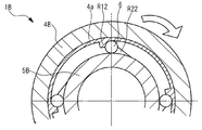
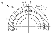
プーリ4Bは駆動側ボール受け部R11の代わりに駆動側ボール受け部R12を備える点と、これに伴いリングギヤ4aをさらに備えている点以外、プーリ4Aと実質的に同一となっている。スライドプレート5Bは従動側ボール受け部R21の代わりに従動側ボール受け部R22を備える点と、溝部5aが特段設けられていない点以外、スライドプレート5Aと実質的に同一となっている。リングギヤ4aはプーリ4Bの内周部およびボディ2とは反対側に位置する壁部に当接した状態でプーリ4Bに固定されている。第2の動力伝達機構は駆動側ボール受け部R12それぞれと従動側ボール受け部R22それぞれと複数(ここでは4つ)のボール6とを有して構成されている。   The pulley 4B is substantially the same as the pulley 4A except that the pulley 4B includes a driving side ball receiving portion R12 instead of the driving side ball receiving portion R11 and further includes a ring gear 4a. The slide plate 5B is substantially the same as the slide plate 5A, except that the driven side ball receiving portion R21 is provided instead of the driven side ball receiving portion R21 and that the groove portion 5a is not particularly provided. The ring gear 4a is fixed to the pulley 4B in contact with the inner peripheral portion of the pulley 4B and the wall portion located on the opposite side of the body 2. The second power transmission mechanism includes each of the driving side ball receiving portions R12, each of the driven side ball receiving portions R22, and a plurality of (here, four) balls 6.

なお、ウォータポンプ1Bでは実施例1の場合と比較してボディ2やシャフト3にも形状が異なっている部分がある。但し、これらは実施例1の場合と同一であってもよい。このためここではボディ2およびシャフト3に関し、実施例1の場合と特に区別することなく、同一の符号を用いることとしている。   Note that in the water pump 1B, the body 2 and the shaft 3 also have different parts as compared to the case of the first embodiment. However, these may be the same as those in the first embodiment. For this reason, here, the same reference numerals are used for the body 2 and the shaft 3 without distinction from the case of the first embodiment.

図7はコイル7非通電時の第2の動力伝達機構の水平断面図である。図8はコイル7非通電時の第2の動力伝達機構の垂直断面図である。駆動側ボール受け部R12はリングギヤ4aに設けられている。駆動側ボール受け部R12は具体的にはリングギヤ4aの内周面から径方向内側に向かって突出するように設けられている。駆動側ボール受け部R12のうち、プーリ4Bの回転方向において前方となる部分にはボール受け面が設けられている。このボール受け面は軸方向に沿った移動でボール6との係合状態が解除できるように設けられており、ボール6に合わせて部分円筒内面状に窪んだ曲面形状を有している。駆動側ボール受け部R12は周方向に沿って均等に複数(ここでは4つ)設けられている。プーリ4Bはリングギヤ4aを備えることで、駆動側ボール受け部R12を備えている。   FIG. 7 is a horizontal sectional view of the second power transmission mechanism when the coil 7 is not energized. FIG. 8 is a vertical sectional view of the second power transmission mechanism when the coil 7 is not energized. The driving side ball receiving portion R12 is provided in the ring gear 4a. Specifically, the drive side ball receiving portion R12 is provided so as to protrude radially inward from the inner peripheral surface of the ring gear 4a. A ball receiving surface is provided in a portion of the driving side ball receiving portion R12 that is forward in the rotation direction of the pulley 4B. The ball receiving surface is provided so that the engaged state with the ball 6 can be released by movement along the axial direction, and has a curved shape that is recessed in the shape of the inner surface of the partial cylinder in accordance with the ball 6. A plurality (four in this case) of driving side ball receiving portions R12 are provided equally along the circumferential direction. The pulley 4B includes a ring gear 4a, and thus includes a drive side ball receiving portion R12.

従動側ボール受け部R22はスライドプレート5Bのうち、プーリ4B側の先端部に設けられている。この点、スライドプレート5Bのうち、プーリ4B側の先端部の径はリングギヤ4aの内周面との間で隙間を有して複数のボール6の配置を同心円状の配置に保持可能な径に縮径されている。そして、従動側ボール受け部R22は先端部外周面から径方向外側に向かって突出するように設けられている。   The driven-side ball receiving portion R22 is provided at the tip of the slide plate 5B on the pulley 4B side. In this respect, the diameter of the tip of the slide plate 5B on the pulley 4B side has a gap with the inner peripheral surface of the ring gear 4a so that the arrangement of the plurality of balls 6 can be maintained in a concentric arrangement. Reduced diameter. The driven ball receiving portion R22 is provided so as to protrude radially outward from the outer peripheral surface of the tip portion.

従動側ボール受け部R22のうち、プーリ4Bの回転方向において後方となる部分にはボール受け面が設けられている。このボール受け面はボール6の径に合わせて部分円筒内面状に窪んだ曲面形状を有している。ボール受け面は例えばボール6に合わせて部分球面状に窪んだ曲面形状であってもよい。従動側ボール受け部R22は周方向に沿って均等に複数(ここでは4つ)設けられている。スライドプレート5Bのうち、プーリ4B側の先端部に設けられた従動側ボール受け部R22は、コイル7の非通電時に軸方向において駆動側ボール受け部R12と位置が重なるように設けられている。   A ball receiving surface is provided on the rear side of the driven ball receiving portion R22 in the rotation direction of the pulley 4B. The ball receiving surface has a curved shape that is recessed in the shape of the inner surface of the partial cylinder in accordance with the diameter of the ball 6. The ball receiving surface may be, for example, a curved surface that is recessed in a partial spherical shape in accordance with the ball 6. A plurality (four in this case) of the driven-side ball receiving portions R22 are equally provided along the circumferential direction. In the slide plate 5B, the driven ball receiving portion R22 provided at the front end portion on the pulley 4B side is provided so as to overlap with the driving side ball receiving portion R12 in the axial direction when the coil 7 is not energized.

ボール6は径方向においてリングギヤ4aの内周部とスライドプレート5Bの先端部外周面との間に介在するように配置されている。また、周方向において隣り合う駆動側ボール受け部R12間それぞれに配置されている。このように配置された複数のボール6はシャフト3に対して同心円状に配置されている。ボール6それぞれはプーリ4Bの回転中に駆動側ボール受け部R12に当接した状態で保持されるようになっている。複数のボール6の数と駆動側ボール受け部R12の数と従動側ボール受け部R22の数とは互いに等しくなっている。   The ball 6 is disposed so as to be interposed between the inner peripheral portion of the ring gear 4a and the outer peripheral surface of the tip end portion of the slide plate 5B in the radial direction. Moreover, it arrange | positions between each drive side ball | bowl receiving part R12 adjacent in the circumferential direction. The plurality of balls 6 arranged in this way are arranged concentrically with respect to the shaft 3. Each of the balls 6 is held in contact with the driving side ball receiving portion R12 while the pulley 4B is rotating. The number of the plurality of balls 6, the number of driving side ball receiving portions R12 and the number of driven side ball receiving portions R22 are equal to each other.

コイル7を非通電にした場合の第2の動力伝達機構の動作は次の通りである。すなわち、コイル7を非通電にした場合にはスプリング8それぞれがスライドプレート5Bをプーリ4B側に駆動する結果、従動側ボール受け部R22が軸方向において駆動側ボール受け部R12と重なる位置に配置される。そしてこの状態で、ボール6それぞれが駆動側ボール受け部R12に当接した状態でプーリ4Bとともに回転し、対応する従動側ボール受け部R22それぞれに到達する。結果、第2の動力伝達機構が係合状態となる。このとき、ボール6それぞれはプーリ4B、スライドプレート5B間の噛み合いを仲介することで、コイル7の非通電時にプーリ4B、スライドプレート5B間の動力伝達を可能にする。   The operation of the second power transmission mechanism when the coil 7 is not energized is as follows. That is, when the coil 7 is de-energized, each spring 8 drives the slide plate 5B toward the pulley 4B. As a result, the driven-side ball receiver R22 is disposed at a position overlapping the drive-side ball receiver R12 in the axial direction. The In this state, the balls 6 rotate together with the pulley 4B in contact with the driving side ball receiving portion R12 and reach the corresponding driven side ball receiving portions R22. As a result, the second power transmission mechanism is engaged. At this time, each ball 6 mediates meshing between the pulley 4B and the slide plate 5B, thereby enabling power transmission between the pulley 4B and the slide plate 5B when the coil 7 is not energized.

図9はコイル7通電時の第2の動力伝達機構の水平断面図である。図10はコイル7通電時の第2の動力伝達機構の垂直断面図である。
コイル7に通電した場合の第2の動力伝達機構の動作は次の通りである。すなわち、コイル7に通電した場合にはコイル7がスプリング8それぞれの付勢力に抗してスライドプレート5Bをボディ2側に駆動する。結果、従動側ボール受け部R22はリングギヤ4a(より具体的には駆動側ボール受け部R12)と軸方向において重なり合わない位置に配置される。そしてこれにより、第2の動力伝達機構の係合状態が解除される。結果、ボール6それぞれを介したプーリ4B、スライドプレート5B間の動力伝達が切断される。
FIG. 9 is a horizontal sectional view of the second power transmission mechanism when the coil 7 is energized. FIG. 10 is a vertical sectional view of the second power transmission mechanism when the coil 7 is energized.
The operation of the second power transmission mechanism when the coil 7 is energized is as follows. That is, when the coil 7 is energized, the coil 7 drives the slide plate 5B to the body 2 side against the urging force of each spring 8. As a result, the driven-side ball receiving portion R22 is disposed at a position that does not overlap with the ring gear 4a (more specifically, the driving-side ball receiving portion R12) in the axial direction. Thereby, the engaged state of the second power transmission mechanism is released. As a result, power transmission between the pulley 4B and the slide plate 5B via the balls 6 is cut off.

かかるウォータポンプ1Bも噛み合い式の動力伝達機構である第2の動力伝達機構を備えることで、ウォータポンプ1Aの場合と同様の作用効果を得ることができる。また、ボール6それぞれをプーリ4B、スライドプレート5B間の噛み合いの仲介に用いることや、従動側ボール受け部R22が軸方向に沿った移動で対応するボール6との係合状態が解除できるように設けられたボール受け面を備える構成とすることで、ウォータポンプ1Aの場合と同様の作用効果を奏することができる。   Such a water pump 1B also includes the second power transmission mechanism, which is a meshing power transmission mechanism, so that the same operational effects as in the case of the water pump 1A can be obtained. Further, each of the balls 6 is used for mediation of meshing between the pulley 4B and the slide plate 5B, and the engaged state with the corresponding ball 6 can be released by the movement of the driven side ball receiving portion R22 along the axial direction. By having a configuration including the provided ball receiving surface, it is possible to achieve the same operational effects as in the case of the water pump 1A.

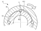
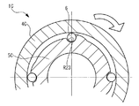
図11はコイル7非通電時の第3の動力伝達機構の水平断面図である。図12はコイル7非通電時の第3の動力伝達機構の垂直断面図である。図13はコイル7通電時の第3の動力伝達機構の水平断面図である。図14はコイル7通電時の第3の動力伝達機構の垂直断面図である。第3の動力伝達機構はウォータポンプ1Cで実現されている。ウォータポンプ1Cはプーリ4Aの代わりにプーリ4Cを備えるとともに、スライドプレート5Aの代わりにスライドプレート5Cを備える点と、これに伴いスプリング8の代わりにスプリング9、10を備えるとともに、噛み合い式の動力伝達機構として第1の動力伝達機構の代わりに第3の動力伝達機構を備える点以外、ウォータポンプ1Aと実質的に同一となっている。なお、ボディ2およびシャフト3に関しては実施例2と同様に同一の符号を用いることとしている。   FIG. 11 is a horizontal sectional view of the third power transmission mechanism when the coil 7 is not energized. FIG. 12 is a vertical sectional view of the third power transmission mechanism when the coil 7 is not energized. FIG. 13 is a horizontal sectional view of the third power transmission mechanism when the coil 7 is energized. FIG. 14 is a vertical sectional view of the third power transmission mechanism when the coil 7 is energized. The third power transmission mechanism is realized by a water pump 1C. The water pump 1C includes a pulley 4C instead of the pulley 4A, a slide plate 5C instead of the slide plate 5A, and springs 9 and 10 instead of the spring 8, and meshing power transmission. The mechanism is substantially the same as the water pump 1 </ b> A except that a third power transmission mechanism is provided instead of the first power transmission mechanism. Note that the same reference numerals are used for the body 2 and the shaft 3 as in the second embodiment.

プーリ4Cは駆動側ボール受け部R11の代わりに駆動側ボール受け部R13を備える点と、スプリング10を摺動させるスプリング摺動部がさらに設けられている点以外、プーリ4Aと実質的に同一となっている。スライドプレート5Cは従動側ボール受け部R21の代わりに従動側ボール受け部R23を備える点と、スプリング9を保持するスプリング保持部がさらに設けられている点以外、スライドプレート5Aと実質的に同一となっている。第3の動力伝達機構は駆動側ボール受け部R13それぞれと従動側ボール受け部R23それぞれと複数(ここでは4つ)のボール6とを有して構成されている。   The pulley 4C is substantially the same as the pulley 4A except that the pulley 4C includes a driving side ball receiving portion R13 instead of the driving side ball receiving portion R11 and a spring sliding portion that slides the spring 10. It has become. The slide plate 5C is substantially the same as the slide plate 5A except that the slide plate 5C includes a driven ball receiving portion R23 instead of the driven side ball receiving portion R21 and a spring holding portion that holds the spring 9 is further provided. It has become. The third power transmission mechanism includes each of the driving side ball receiving portions R13, each of the driven side ball receiving portions R23, and a plurality of (here, four) balls 6.

駆動側ボール受け部R13はプーリ4Cの内周部に溝状に設けられている。駆動側ボール受け部R13については後に詳述する。従動側ボール受け部R23はスライドプレート5Cの外周部に部分球状に窪んだ空間を形成するように設けられている。ボール6は従動側ボール受け部R23に保持されるようになっている。従動側ボール受け部R23は周方向に沿って均等に複数(ここでは4つ)設けられている。従動側ボール受け部R23の数とボール6の数とは互いに等しくなっている。   The driving side ball receiving portion R13 is provided in a groove shape on the inner peripheral portion of the pulley 4C. The driving side ball receiving portion R13 will be described in detail later. The driven-side ball receiving portion R23 is provided so as to form a partially spherical space in the outer peripheral portion of the slide plate 5C. The ball 6 is held by the driven side ball receiving portion R23. A plurality (four in this case) of the driven-side ball receiving portions R23 are equally provided along the circumferential direction. The number of driven side ball receiving portions R23 and the number of balls 6 are equal to each other.

スプリング9はボディ2、スライドプレート5C間に設けられている。スプリング9はプーリ4Cに接近する方向にスライドプレート5Cを駆動する。スプリング9は周方向に沿って均等に複数設けられている。スプリング10はプーリ4C、スライドプレート5C間に設けられている。スプリング10はボディ2に接近する方向にスライドプレート5Cを駆動する。スプリング10はスプリング9それぞれに対応させて周方向に沿って均等に複数設けられている。このため、スプリング9、10の数は互いに等しくなっている。   The spring 9 is provided between the body 2 and the slide plate 5C. The spring 9 drives the slide plate 5C in a direction approaching the pulley 4C. A plurality of springs 9 are equally provided along the circumferential direction. The spring 10 is provided between the pulley 4C and the slide plate 5C. The spring 10 drives the slide plate 5 </ b> C in a direction approaching the body 2. A plurality of springs 10 are equally provided along the circumferential direction so as to correspond to the respective springs 9. For this reason, the number of the springs 9 and 10 is mutually equal.

スプリング10の付勢力はスプリング9の付勢力よりも小さく設定されている。このため、ウォータポンプ1Cではコイル7非通電時に複数のスプリング9が複数のスプリング10の付勢力に抗してスライドプレート5Cをプーリ4C側に駆動する。また、コイル7通電時にコイル7が複数のスプリング10とともに複数のスプリング9の付勢力に抗してスライドプレート5Cをボディ2側に駆動する。複数のスプリング9は駆動部を構成している。   The biasing force of the spring 10 is set smaller than the biasing force of the spring 9. For this reason, in the water pump 1C, when the coil 7 is not energized, the springs 9 drive the slide plate 5C toward the pulley 4C against the urging force of the springs 10. Further, when the coil 7 is energized, the coil 7 drives the slide plate 5 </ b> C toward the body 2 against the urging force of the plurality of springs 9 together with the plurality of springs 10. The plurality of springs 9 constitute a drive unit.

図15は駆動側ボール受け部R13の説明図である。駆動側ボール受け部R13は具体的にはコイル7通電時のスライドプレート5Cの配置に応じた従動側ボール受け部R23に対応させて、プーリ4Cの内周部に一周に亘ってリング状の溝を形成するように設けられている。また、リング状の溝からコイル7非通電時のスライドプレート5Cの配置に応じた従動側ボール受け部R23に対応する位置まで螺旋状に延伸する溝を周方向に沿って均等に複数(ここでは4つ)形成するように設けられている。この螺旋状の溝の数は従動側ボール受け部R23の数およびボール6の数と互いに等しくなっている。   FIG. 15 is an explanatory diagram of the driving side ball receiving portion R13. Specifically, the drive-side ball receiving portion R13 corresponds to the driven-side ball receiving portion R23 corresponding to the arrangement of the slide plate 5C when the coil 7 is energized, and the ring-like groove extends around the inner peripheral portion of the pulley 4C. Are provided. Further, a plurality of grooves extending in a spiral manner from the ring-shaped groove to the position corresponding to the driven-side ball receiving portion R23 corresponding to the arrangement of the slide plate 5C when the coil 7 is not energized (here, a plurality of grooves) 4) It is provided to form. The number of spiral grooves is equal to the number of driven side ball receiving portions R23 and the number of balls 6.

コイル7を非通電にした場合およびコイル7に通電した場合の第3の動力伝達機構の動作は次の通りである。すなわち、コイル7を非通電にした場合には、スプリング9それぞれがスプリング10それぞれの付勢力に抗してスライドプレート5Cをプーリ4C側に駆動する。このとき、プーリ4Cから見て駆動側ボール受け部R13のうち、リング状の溝に沿って空転していたボール6は螺旋状の溝にそれぞれ導かれる。そして、その後螺旋状の溝を奥に向かって進み、溝の終端部に到達する。結果、第3の動力伝達機構が係合状態となる。このとき、ボール6それぞれはプーリ4C、スライドプレート5C間の噛み合いを仲介することで、コイル7の非通電時にプーリ4C、スライドプレート5C間の動力伝達を可能にする。   The operation of the third power transmission mechanism when the coil 7 is de-energized and when the coil 7 is energized is as follows. That is, when the coil 7 is de-energized, each spring 9 drives the slide plate 5C toward the pulley 4C against the urging force of each spring 10. At this time, in the driving-side ball receiving portion R13 as viewed from the pulley 4C, the balls 6 that have idled along the ring-shaped groove are respectively guided to the spiral grooves. After that, the spiral groove is advanced toward the back and reaches the end of the groove. As a result, the third power transmission mechanism is engaged. At this time, each ball 6 mediates meshing between the pulley 4C and the slide plate 5C, thereby enabling power transmission between the pulley 4C and the slide plate 5C when the coil 7 is not energized.

コイル7に通電した場合には、コイル7がスプリング10それぞれとともにスプリング9それぞれの付勢力に抗してスライドプレート5Cをボディ2側に駆動する。このとき、螺旋状の溝の終端部に当接していたボール6それぞれは螺旋状の溝を入口側に向かって進み、リング状の溝に到達する。そしてこれにより、第3の動力伝達機構の係合状態が解除される結果、プーリ4C、スライドプレート5C間の動力伝達が切断される。   When the coil 7 is energized, the coil 7 drives the slide plate 5 </ b> C toward the body 2 against the urging forces of the springs 9 as well as the springs 10. At this time, each ball 6 that has been in contact with the terminal end of the spiral groove travels along the spiral groove toward the inlet side and reaches the ring-shaped groove. As a result, the engagement state of the third power transmission mechanism is released, so that the power transmission between the pulley 4C and the slide plate 5C is disconnected.

かかるウォータポンプ1Cも噛み合い式の動力伝達機構である第3の動力伝達機構を備えることで、ウォータポンプ1Aの場合と同様の作用効果を得ることができる。また、ボール6それぞれをプーリ4C、スライドプレート5C間の噛み合いの仲介に用いることで、ウォータポンプ1Aの場合と同様の作用効果を奏することができる。   Such a water pump 1C also includes the third power transmission mechanism that is a meshing type power transmission mechanism, so that the same operational effects as in the case of the water pump 1A can be obtained. Further, by using each of the balls 6 for mediation of the engagement between the pulley 4C and the slide plate 5C, the same operational effects as in the case of the water pump 1A can be achieved.

ウォータポンプ1Cはボール6それぞれでプーリ4C、スライドプレート5C間の噛み合いを仲介するにあたって、噛み合い式の動力伝達機構がプーリ4Cに設けられた溝状の駆動側ボール受け部R13と、スライドプレート5Cに設けられ、ボール6を保持する従動側ボール受け部R23とを備えるとともに、駆動側ボール受け部R13が非係合時にボール6それぞれを空転させるリング状の溝と、リング状の溝に連通し、スライドプレート5Cの軸方向に沿った移動に応じてボール6それぞれを個別に案内するとともに、終端部でボール6それぞれに個別に当接する螺旋状の溝とを備える構成となっている。このため、ウォータポンプ1Cは係合時にスライドプレート5Cの回転をプーリ4Cの回転に同期させるようにして、係合時に加わる衝撃を緩和することもできる。   When the water pump 1C mediates the engagement between the pulley 4C and the slide plate 5C with each ball 6, a mesh-type power transmission mechanism is provided between the groove-shaped drive side ball receiving portion R13 provided on the pulley 4C and the slide plate 5C. A driven-side ball receiving portion R23 that holds the ball 6 and communicates with a ring-shaped groove that idles the balls 6 when the driving-side ball receiving portion R13 is not engaged, and the ring-shaped groove, Each of the balls 6 is individually guided according to the movement of the slide plate 5C along the axial direction, and includes a spiral groove that individually contacts each of the balls 6 at the terminal portion. For this reason, the water pump 1C can relieve the impact applied at the time of engagement by synchronizing the rotation of the slide plate 5C with the rotation of the pulley 4C at the time of engagement.

以上、本発明の実施例について詳述したが、本発明はかかる特定の実施例に限定されるものではなく、特許請求の範囲に記載された本発明の要旨の範囲内において、種々の変形・変更が可能である。   Although the embodiments of the present invention have been described in detail above, the present invention is not limited to such specific embodiments, and various modifications and changes can be made within the scope of the gist of the present invention described in the claims. It can be changed.

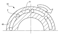
例えば噛み合い式の動力伝達機構は必ずしもボール部を備えていなくてもよい。図16は第1の変形例であるウォータポンプ1Dの水平断面図である。図17は第1の変形例であるウォータポンプ1Dの垂直断面図である。ウォータポンプ1Dはプーリ4Aの代わりにプーリ4Dを備えるとともに、スライドプレート5Aの代わりにスライドプレート5Dを備える点と、ボール6を特段備えていない点以外、ウォータポンプ1Aと実質的に同一となっている。プーリ4Dは駆動側ボール受け部R11の代わりにピン溝部Hを備える点以外、プーリ4Dと実質的に同一となっている。スライドプレート5Dは従動側ボール受け部R21の代わりにピンPを備える点以外、スライドプレート5Aと実質的に同一となっている。   For example, a meshing power transmission mechanism does not necessarily have a ball portion. FIG. 16 is a horizontal sectional view of a water pump 1D which is a first modification. FIG. 17 is a vertical sectional view of a water pump 1D which is a first modification. The water pump 1D is substantially the same as the water pump 1A except that the water pump 1D includes a pulley 4D instead of the pulley 4A, a slide plate 5D instead of the slide plate 5A, and a ball 6 is not particularly provided. Yes. The pulley 4D is substantially the same as the pulley 4D except that a pin groove portion H is provided instead of the driving side ball receiving portion R11. The slide plate 5D is substantially the same as the slide plate 5A except that a pin P is provided instead of the driven-side ball receiving portion R21.

ピン溝部Hはプーリ4Dのうち、スライドプレート5Dと対向する側の部分に設けられている。ピン溝部Hは所定の深さで周方向に沿って円弧状に設けられている。ピン溝部Hの深さ(軸方向に沿った寸法)はピンPの長さよりも大きく設定されている。ピン溝部Hのうち、プーリ4Dの回転方向において後方となる部分は、ピンPに合わせた形状を有している。ピン溝部Hは周方向に沿って均等に複数(ここでは8つ)設けられている。   The pin groove portion H is provided in a portion of the pulley 4D that faces the slide plate 5D. The pin groove portion H is provided in an arc shape along the circumferential direction at a predetermined depth. The depth (dimension along the axial direction) of the pin groove portion H is set larger than the length of the pin P. Of the pin groove portion H, the rear portion in the rotation direction of the pulley 4 </ b> D has a shape matched to the pin P. A plurality (eight in this case) of pin groove portions H are provided uniformly along the circumferential direction.

ピンPはスライドプレート5Dのうち、プーリ4Dと対向する側の部分に設けられている。ピンPはスライドプレート5Dからプーリ4D側に向かって軸方向に沿って延伸するように設けられている。ピンPは先端部が球面状に形成された円柱状の形状を有している。ピンPは周方向に沿って均等に複数(ここでは8つ)設けられている。ピン溝部Hの数とピンPの数とは互いに等しくなっている。   The pin P is provided in a portion of the slide plate 5D that faces the pulley 4D. The pin P is provided so as to extend along the axial direction from the slide plate 5D toward the pulley 4D. The pin P has a cylindrical shape whose tip is formed in a spherical shape. A plurality of pins P (eight here) are provided evenly along the circumferential direction. The number of pin groove portions H and the number of pins P are equal to each other.

ウォータポンプ1Dでは、噛み合い式の動力伝達機構がボール受け部R11、R21それぞれの代わりにピン溝部HそれぞれとピンPそれぞれとを備えている。この点、かかるウォータポンプ1Dでも、コンパクトで簡素な構造を実現するとともに消費電力の更なる低減を図ることができる。なお、この場合にはピンPの抜き差しに必要なスライドプレート5Dのストロークを確保する必要がある分、コンパクト化に不利となる虞がある。また、係合状態の解除時に係合状態が持続するストロークが長くなる分、消費電力の低減に不利となる虞がある。このほか係合時に加わる衝撃に対し、強度面で不利となる虞がある。   In the water pump 1D, the meshing power transmission mechanism includes pin groove portions H and pins P instead of the ball receiving portions R11 and R21. In this respect, the water pump 1D can achieve a compact and simple structure and further reduce power consumption. In this case, since it is necessary to secure the stroke of the slide plate 5D necessary for inserting and removing the pin P, there is a possibility that it may be disadvantageous for downsizing. In addition, there is a risk that it may be disadvantageous in reducing power consumption because the stroke in which the engaged state is maintained when the engaged state is released becomes longer. In addition, there is a possibility that it is disadvantageous in terms of strength against an impact applied during engagement.

図18は第2の変形例であるウォータポンプ1Eの水平断面図である。ウォータポンプ1Eはプーリ4Aの代わりにプーリ4Eを備えるとともに、スライドプレート5Aの代わりにスライドプレート5Eを備える点と、ボール6を特段備えていない点以外、ウォータポンプ1Aと実質的に同一となっている。プーリ4Eは駆動側ボール受け部R11の代わりに駆動側傘歯部G1を備える点以外、プーリ4Aと実質的に同一となっている。スライドプレート5Eは従動側ボール受け部R21の代わりに従動側傘歯部G2を備える点以外、スライドプレート5Aと実質的に同一となっている。   FIG. 18 is a horizontal sectional view of a water pump 1E which is a second modification. The water pump 1E is substantially the same as the water pump 1A except that the water pump 1E includes a pulley 4E instead of the pulley 4A, a slide plate 5E instead of the slide plate 5A, and a ball 6 is not particularly provided. Yes. The pulley 4E is substantially the same as the pulley 4A except that the pulley 4E includes a drive-side bevel tooth portion G1 instead of the drive-side ball receiving portion R11. The slide plate 5E is substantially the same as the slide plate 5A except that it includes a driven side bevel tooth portion G2 instead of the driven side ball receiving portion R21.

駆動側傘歯部G1はプーリ4Eのうち、スライドプレート5Eと対向する側の部分に一周に亘って設けられている。駆動側傘歯部G1の歯それぞれは周方向に沿って均等に複数設けられている。従動側傘歯部G2はスライドプレート5Eのうち、プーリ4Eと対向する側の部分に一周に亘って設けられている。従動側傘歯部G2の歯それぞれは周方向に沿って均等に複数設けられている。駆動側傘歯部G1の歯数と従動側傘歯部G2の歯数とは互いに等しくなっている。駆動側傘歯部G1の歯それぞれと従動側傘歯部G2の歯それぞれとはスライドプレート5Eの軸方向に沿った移動に応じて、係合および係合の解除ができるように設けられている。   The drive side bevel tooth portion G1 is provided over the circumference of the portion of the pulley 4E on the side facing the slide plate 5E. A plurality of teeth of the drive-side bevel tooth portion G1 are equally provided along the circumferential direction. The driven-side bevel tooth portion G2 is provided over the entire portion of the slide plate 5E on the side facing the pulley 4E. A plurality of teeth of the driven side bevel tooth portion G2 are equally provided along the circumferential direction. The number of teeth of the driving side bevel tooth portion G1 and the number of teeth of the driven side bevel tooth portion G2 are equal to each other. Each tooth of the drive-side bevel tooth portion G1 and each tooth of the driven-side bevel tooth portion G2 are provided so that they can be engaged and released according to the movement of the slide plate 5E along the axial direction. .

ウォータポンプ1Eでは、噛み合い式の動力伝達機構がボール受け部R11、R21それぞれの代わりに傘歯部G1、G2を備えている。この点、かかるウォータポンプ1Eでもコンパクトで簡素な構造を実現するとともに、消費電力の更なる低減を図ることができる。但し、この場合には従動側傘歯部G2の抜き差しに必要なスライドプレート5Eのストロークを確保する必要がある分、コンパクト化に不利となる虞がある。また、係合状態の解除に係合状態が持続するストロークが長くなる分、消費電力の低減に不利となる虞がある。このほか係合時に加わる衝撃に対し、例えば歯元において強度面で不利となる虞がある。   In the water pump 1E, the meshing power transmission mechanism includes bevel tooth portions G1 and G2 instead of the ball receiving portions R11 and R21. In this respect, the water pump 1E can achieve a compact and simple structure and can further reduce power consumption. However, in this case, since it is necessary to secure the stroke of the slide plate 5E necessary for the insertion and removal of the driven side bevel tooth portion G2, there is a possibility that it may be disadvantageous for downsizing. Moreover, there is a possibility that it may be disadvantageous for reduction of power consumption because the stroke in which the engaged state is maintained for releasing the engaged state becomes longer. In addition, there is a risk that the impact applied during engagement may be disadvantageous in terms of strength at the tooth root, for example.

ウォータポンプ 1A、1B、1C、1D、1E
プーリ 4A、4B、4C、4D、4E
スライドプレート 5A、5B、5C、5D、5E
ボール 6
コイル 7
Water pump 1A, 1B, 1C, 1D, 1E
Pulley 4A, 4B, 4C, 4D, 4E
Slide plate 5A, 5B, 5C, 5D, 5E
Ball 6
Coil 7

Claims (2)

駆動側回転体と、
前記駆動側回転体から動力が伝達されるスライド式の従動側回転体と、
ボディに設けられ、通電時に前記駆動側回転体から離間して前記ボディに近接する方向に前記従動側回転体を駆動するコイルと、
前記ボディと従動側回転体との間に位置し、かつ前記従動側回転体とともに回転し、前記駆動側回転体に接近する方向に前記従動側回転体を駆動する駆動部と、を備え、
前記コイルの通電時に前記駆動側回転体前記従動側回転体との間の動力伝達を切断し、前記コイルの非通電時に前記駆動側回転体前記従動側回転体との間の動力伝達を可能にする噛み合い式の動力伝達機構を備えるウォータポンプ。
A driving side rotating body;
A slide driven driven rotating body to which power is transmitted from the driving side rotating body;
Provided in the body, and spaced apart from the driving-side rotator when energized coil for driving the driven side rotational member in a direction coming close to the body,
A drive unit that is positioned between the body and the driven-side rotator, rotates with the driven-side rotator, and drives the driven-side rotator in a direction approaching the drive-side rotator;
The power transmission between the power transmission is cut, the driving side rotational member at the time of non-energization of the coil and the driven side rotational member between the driving side rotational member and the driven-side rotating member when energized the coil A water pump equipped with a meshing power transmission mechanism that enables this.
請求項1記載のウォータポンプであって、
前記動力伝達機構が前記駆動側回転体、前記従動側回転体間に介在するように設けられ、前記駆動側回転体、前記従動側回転体間の噛み合いを仲介するボール部を備えるウォータポンプ。
The water pump according to claim 1,
A water pump comprising: a ball portion that is provided so that the power transmission mechanism is interposed between the driving side rotating body and the driven side rotating body and mediates meshing between the driving side rotating body and the driven side rotating body.
JP2011196020A 2011-09-08 2011-09-08 Water pump Expired - Fee Related JP5716615B2 (en)

Priority Applications (1)

Application Number Priority Date Filing Date Title
JP2011196020A JP5716615B2 (en) 2011-09-08 2011-09-08 Water pump

Applications Claiming Priority (1)

Application Number Priority Date Filing Date Title
JP2011196020A JP5716615B2 (en) 2011-09-08 2011-09-08 Water pump

Publications (2)

Publication Number Publication Date
JP2013057293A JP2013057293A (en) 2013-03-28
JP5716615B2 true JP5716615B2 (en) 2015-05-13

Family

ID=48133371

Family Applications (1)

Application Number Title Priority Date Filing Date
JP2011196020A Expired - Fee Related JP5716615B2 (en) 2011-09-08 2011-09-08 Water pump

Country Status (1)

Country Link
JP (1) JP5716615B2 (en)

Families Citing this family (4)

* Cited by examiner, † Cited by third party
Publication number Priority date Publication date Assignee Title
DE112013004673T5 (en) 2012-09-25 2015-07-09 Toyota Jidosha Kabushiki Kaisha clutch
WO2015012211A1 (en) 2013-07-25 2015-01-29 トヨタ自動車 株式会社 Clutch
JP5799058B2 (en) * 2013-07-30 2015-10-21 三桜工業株式会社 Negative pressure pump and cylinder head cover
JP6343091B2 (en) * 2015-02-23 2018-06-13 Gknドライブラインジャパン株式会社 Differential device

Family Cites Families (4)

* Cited by examiner, † Cited by third party
Publication number Priority date Publication date Assignee Title
JPH05272558A (en) * 1992-03-25 1993-10-19 Hitachi Ltd Clutch
JP4525046B2 (en) * 2003-10-15 2010-08-18 シンフォニアテクノロジー株式会社 Electromagnetic ball clutch
DE102006023447A1 (en) * 2006-05-18 2007-11-22 Arvinmeritor Light Vehicle Systems-France Electromechanical coupling
JP2010203406A (en) * 2009-03-05 2010-09-16 Toyota Motor Corp Water pump

Also Published As

Publication number Publication date
JP2013057293A (en) 2013-03-28

Similar Documents

Publication Publication Date Title
JP5716615B2 (en) Water pump
JP2009121676A (en) Power transmitter
JP2006275178A (en) Electromagnetic clutch
WO2018154903A1 (en) Electrically powered tool
JP5494547B2 (en) Valve timing adjustment device
JP4572912B2 (en) Starter
US9494202B2 (en) Clutch
WO2014050870A1 (en) Clutch
JP2013072369A (en) Pump device
JPH09209890A (en) Starter with planetary gear speed reduction mechanism
JP3555539B2 (en) Shock absorber
JP2013245573A (en) Gas compressor and electromagnetic clutch used for the same
JP2013083165A (en) Starter
JP4199105B2 (en) Electromagnetic brake cooling structure of phase variable device in automotive engine
JP4525046B2 (en) Electromagnetic ball clutch
CN212429561U (en) Electromagnetic clutch
JP2015025495A (en) Clutch
JP2019183999A (en) Clutch device
JP2013234699A (en) Magnetic coupling device
JP2017048681A (en) pump
JP2003314587A (en) Electromagnetic interlocking device
CN209180257U (en) Without nose formula starter motor one-way clutch
JP2005221039A (en) Power transmitting mechanism
WO2018078921A1 (en) Friction clutch
JP2020131950A (en) Oil pump drive device

Legal Events

Date Code Title Description
A621 Written request for application examination

Free format text: JAPANESE INTERMEDIATE CODE: A621

Effective date: 20131025

A131 Notification of reasons for refusal

Free format text: JAPANESE INTERMEDIATE CODE: A131

Effective date: 20140729

A977 Report on retrieval

Free format text: JAPANESE INTERMEDIATE CODE: A971007

Effective date: 20140730

A521 Request for written amendment filed

Free format text: JAPANESE INTERMEDIATE CODE: A523

Effective date: 20140924

TRDD Decision of grant or rejection written
A01 Written decision to grant a patent or to grant a registration (utility model)

Free format text: JAPANESE INTERMEDIATE CODE: A01

Effective date: 20150217

A61 First payment of annual fees (during grant procedure)

Free format text: JAPANESE INTERMEDIATE CODE: A61

Effective date: 20150302

R151 Written notification of patent or utility model registration

Ref document number: 5716615

Country of ref document: JP

Free format text: JAPANESE INTERMEDIATE CODE: R151

LAPS Cancellation because of no payment of annual fees