JP5784299B2 - Data processing apparatus and image processing apparatus - Google Patents
Data processing apparatus and image processing apparatus Download PDFInfo
- Publication number
- JP5784299B2 JP5784299B2 JP2010245478A JP2010245478A JP5784299B2 JP 5784299 B2 JP5784299 B2 JP 5784299B2 JP 2010245478 A JP2010245478 A JP 2010245478A JP 2010245478 A JP2010245478 A JP 2010245478A JP 5784299 B2 JP5784299 B2 JP 5784299B2
- Authority
- JP
- Japan
- Prior art keywords
- data
- unit
- output
- image processing
- buffer
- Prior art date
- Legal status (The legal status is an assumption and is not a legal conclusion. Google has not performed a legal analysis and makes no representation as to the accuracy of the status listed.)
- Active
Links
Images


Classifications
-
- G—PHYSICS
- G06—COMPUTING; CALCULATING OR COUNTING
- G06F—ELECTRIC DIGITAL DATA PROCESSING
- G06F5/00—Methods or arrangements for data conversion without changing the order or content of the data handled
- G06F5/06—Methods or arrangements for data conversion without changing the order or content of the data handled for changing the speed of data flow, i.e. speed regularising or timing, e.g. delay lines, FIFO buffers; over- or underrun control therefor
Description
本発明は、データ処理装置および画像処理装置に関する。 The present invention relates to a data processing device and an image processing device.
静止画用カメラ、動画用カメラ、医療用内視鏡カメラ、または産業用内視鏡カメラなどの撮像装置においては、撮像装置の画素数の向上、連写速度の向上に伴って、膨大な画素数の画像データを短時間で処理する画像処理装置が望まれている。このような画像データの処理を高速化するための技術として、図14(a)に示したように、画像処理にパイプライン処理を用いる技術が知られている(特許文献1参照)。この特許文献1で開示された技術によると、1フレームの静止画像を、複数の重複(オーバーラップ)部分、いわゆる「のり代部分」を持つブロックに分割する。そして、分割したブロック毎に、「フレームメモリ→イメージプロセス1→イメージプロセス2→・・・→イメージプロセスn→JPEG(Joint Photographic Experts Group)処理→フレームメモリ」というように、複数の画像処理を直結した処理を行うようになっている。しかし、分割したそれぞれのブロック内では処理を行う画像データの流れが連続しているが、異なるブロックとの間ではデータの流れが連続していない(図14(b)参照)。そのため、パイプライン処理の全体を制御するシーケンサが、パイプラインを構成する各処理モジュール(処理部)において処理する画像データの範囲などの設定を、各ブロックのパイプライン処理を開始する前に、毎回設定し直していた(図14(c)参照)。このように一連のパイプライン処理毎に画像処理の動作を制御した場合、パイプラインを構成する処理モジュールのいずれかが動作していない時間的なロスの期間が、それぞれのブロックの処理の間に発生してしまう。この処理モジュールが動作していないロス時間が、1フレームの静止画像の処理時間に影響することとなる。
In an imaging device such as a still image camera, a video camera, a medical endoscopic camera, or an industrial endoscopic camera, an enormous number of pixels are required as the number of pixels of the imaging device increases and the continuous shooting speed increases. An image processing apparatus that processes a large number of image data in a short time is desired. As a technique for speeding up the processing of such image data, as shown in FIG. 14A, a technique using pipeline processing for image processing is known (see Patent Document 1). According to the technique disclosed in
また、画像データの処理をさらに高速化するための技術として、図15に示したように、パイプラインを構成する各処理モジュール毎に、当該処理モジュールによる処理が完了したことを表す割込み信号を、シーケンサに出力する技術も開示されている(特許文献2参照)。この特許文献2で開示された技術では、シーケンサが、処理モジュールから割込み信号が入力されるたびに、その処理モジュールの設定を個別に変更する。これにより、シーケンサがそれぞれの処理モジュールの設定を変更するタイミングが、分割したブロックの処理を開始するタイミング毎ではなくなり、各処理モジュールの処理が完了したタイミング毎となる。このようにシーケンサが各処理モジュールの設定を変更するタイミングをそれぞれの処理モジュール毎にすることによって、特許文献2の技術では、各ブロック間の処理における時間的なロスを低減し、1フレームの静止画像の処理を高速化している(図16(a)参照)。
Further, as a technique for further speeding up the processing of the image data, as shown in FIG. 15, for each processing module constituting the pipeline, an interrupt signal indicating that the processing by the processing module is completed, A technique for outputting to a sequencer is also disclosed (see Patent Document 2). In the technique disclosed in
しかしながら、パイプラインを構成する処理モジュールの1つの処理モジュールに着目(例えば、図16(b)に示したように、YC処理モジュールに着目)してみると、処理モジュールに入力してから出力されるまでに遅延時間が生じている。この遅延時間と、処理モジュールの設定の変更に要する時間とを合わせた時間、すなわち、最初のブロックに対応した出力が完了してから次のブロックに対応した出力が開始されるまでの時間は、画像データの処理の高速化におけるロス時間となってしまう、という問題がある。 However, when attention is paid to one of the processing modules constituting the pipeline (for example, attention is paid to the YC processing module as shown in FIG. 16B), the data is output after being input to the processing module. There is a delay time. The combined time of the delay time and the time required for changing the setting of the processing module, that is, the time from the completion of the output corresponding to the first block to the start of the output corresponding to the next block is There is a problem that a loss time is required in speeding up the processing of image data.
このロス時間の問題は、例えば、タップ数が大きいフィルタ処理を行う処理モジュールや、撮像装置のレンズの歪曲収差を補正する処理モジュールなどのように、処理モジュールに入力してから出力されるまでの遅延時間が長い処理モジュール程、より顕著な問題となる。 The problem of this loss time is, for example, a process module that performs a filter process with a large number of taps, a process module that corrects distortion aberration of a lens of an imaging device, and the like until it is output after being input to the process module. A processing module with a longer delay time becomes a more significant problem.
本発明は、上記の課題認識に基づいてなされたものであり、処理モジュールに入力してから出力されるまでの遅延時間が長いデータ処理を含むパイプライン処理において、各パイプライン処理におけるロス時間を低減することができるデータ処理装置および画像処理装置を提供することを目的としている。 The present invention has been made on the basis of the above problem recognition, and in pipeline processing including data processing with a long delay time from input to output to a processing module, loss time in each pipeline processing is reduced. An object of the present invention is to provide a data processing apparatus and an image processing apparatus that can be reduced.
上記の課題を解決するため、本発明のデータ処理装置は、パイプライン接続された複数の画像処理モジュールを用いて、画像データを処理するデータ処理装置であって、 前記画像処理モジュールは、前記画像データの領域を複数行から成る複数の重複ブロックに分割し、第1のブロックにおける最後の行の画像処理を行う際に必要とするデータ数と、該第1のブロックの次に処理を行う第2のブロックにおける最初の行の画像処理を行う際に必要とするデータ数とを合わせた数のデータを記憶する記憶容量のバッファ部と、入力データを、前記バッファ部に書き込むデータ書き込み制御部と、前記バッファ部に記憶されているデータを読み出し、該読み出したデータに基づいて生成した出力データを出力するデータ読み出し制御部と、前記データ書き込み制御部がデータを書き込む前記バッファ部内の記憶領域、および前記データ読み出し制御部がデータを読み出す前記バッファ部内の記憶領域を決定するバッファ領域決定部と、を備え、前記データ書き込み制御部は、前記バッファ領域決定部によって決定された前記記憶領域に前記入力データを書き込み、前記入力データの書き込みが完了したときに、データの書き込みが完了したことを表すデータ書き込み完了信号を出力し、前記データ読み出し制御部は、前記バッファ領域決定部によって決定された前記記憶領域に記憶されているデータを読み出し、該読み出したデータに基づいて生成した出力データの出力が完了したときに、データの読み出しが完了したことを表すデータ読み出し完了信号を出力する、ことを特徴とする。
In order to solve the above problems, a data processing apparatus of the present invention is a data processing apparatus that processes image data using a plurality of pipeline-connected image processing modules, and the image processing module includes the image processing module. The data area is divided into a plurality of overlapping blocks consisting of a plurality of rows, and the number of data required when image processing of the last row in the first block is performed, and the first processing is performed after the first block. A buffer unit having a storage capacity for storing a total number of data necessary for image processing of the first row in the
また、本発明の前記データ書き込み制御部は、前記バッファ領域決定部によって決定された前記バッファ部内の書き込み可能領域に前記入力データを書き込み、予め定められた数の前記入力データの前記バッファ部への書き込みが完了したときに、データの書き込みが完了したと判定し、前記データ読み出し制御部は、前記バッファ領域決定部によって決定された前記バッファ部内の読み出し可能領域からデータを読み出し、予め定められた数の前記バッファ部からの読み出しが完了し、該読み出したデータに基づいて生成した出力データの出力が完了したときに、データの読み出しが完了したと判定し、前記バッファ領域決定部は、前記データ書き込み制御部による前記入力データの書き込み状態、および前記データ読み出し制御部によるデータの読み出し状態に応じて、前記バッファ部内の前記書き込み可能領域および前記読み出し可能領域を変更する、ことを特徴とする。 The data write control unit of the present invention writes the input data to a writable area in the buffer unit determined by the buffer area determination unit, and a predetermined number of the input data to the buffer unit is written. When the writing is completed, it is determined that the data writing has been completed, and the data read control unit reads the data from the readable area in the buffer unit determined by the buffer area determination unit, and determines a predetermined number When the reading from the buffer unit is completed and the output of the output data generated based on the read data is completed, it is determined that the data reading is completed, and the buffer area determination unit Write state of the input data by the control unit, and by the data read control unit In response to a read state of over data, changing the writable area and the reading area in the buffer unit, characterized in that.
また、本発明の前記バッファ領域決定部は、前記データ書き込み制御部によってデータが書き込まれた前記バッファ部内の前記記憶領域を、有効なデータが記憶され、該記憶されたデータを読み出すことができる前記読み出し可能領域に決定し、前記データ読み出し制御部によってデータが読み出された前記バッファ部内の前記記憶領域を、空き領域であり、前記入力データを書き込むことができる前記書き込み可能領域に決定する、ことを特徴とする。 Further, the buffer area determining unit of the present invention, the storage area of the data writing control unit in the buffer section the data is written by the valid data is stored, that to read out the stored data The readable area is determined, and the storage area in the buffer unit from which data is read by the data read control unit is an empty area and the writable area in which the input data can be written is determined. It is characterized by that.
また、本発明の前記データ読み出し制御部は、前記読み出したデータに基づいてフィルタ処理した出力データを生成するフィルタ処理部、を備え、前記記憶容量は、前記フィルタ処理部がフィルタ処理を行う際に必要とするデータ数に基づいて決定する、ことを特徴とする。 Further, the data read control unit of the present invention includes a filter processing unit that generates output data that has been subjected to filter processing based on the read data, and the storage capacity is obtained when the filter processing unit performs the filter processing. It is determined based on the number of necessary data.
また、本発明の画像処理装置は、パイプライン接続された複数の画像処理モジュールを用いて、画像データを処理するデータ処理装置であって、前記画像処理モジュールは、前記画像データの領域を複数行から成る複数の重複ブロックに分割し、第1のブロックにおける最後の行の画像処理を行う際に必要とするデータ数と、該第1のブロックの次に処理を行う第2のブロックにおける最初の行の画像処理を行う際に必要とするデータ数とを合わせた数のデータを記憶する記憶容量のバッファ部と、入力データを、前記バッファ部に書き込むデータ書き込み制御部と、前記バッファ部に記憶されているデータを読み出し、該読み出したデータに基づいて生成した出力データを出力するデータ読み出し制御部と、前記データ書き込み制御部がデータを書き込む前記バッファ部内の記憶領域、および前記データ読み出し制御部がデータを読み出す前記バッファ部内の記憶領域を決定するバッファ領域決定部と、を有し、前記データ書き込み制御部が前記バッファ領域決定部によって決定された前記記憶領域に前記入力データを書き込み、前記入力データの書き込みが完了したときに、データの書き込みが完了したことを表すデータ書き込み完了信号と、前記データ読み出し制御部が前記バッファ領域決定部によって決定された前記記憶領域に記憶されているデータを読み出し、該読み出したデータに基づいて生成した出力データの出力が完了したときに、データの読み出しが完了したことを表すデータ読み出し完了信号と、をそれぞれ出力するデータ処理装置、を備え、前記データ書き込み完了信号が出力された後に、前記データ書き込み制御部による画像データの書き込みに係る設定を行い、前記データ読み出し完了信号が出力された後に、前記データ読み出し制御部による画像データの読み出しに係る設定を行う、ことを特徴とする。 The image processing apparatus of the present invention, by using a plurality of image processing modules connected pipeline, a data processing apparatus for processing image data, said image processing module, multi-line area of the image data Are divided into a plurality of overlapping blocks, and the number of data required for image processing of the last row in the first block and the first in the second block to be processed next to the first block A buffer unit having a storage capacity for storing the total number of data required when performing image processing for a row, a data write control unit for writing input data to the buffer unit, and a memory unit for storing the input data The data read control unit that reads out the read data and outputs the output data generated based on the read data, and the data write control unit A storage area in the buffer unit for writing data, and a buffer area determination unit for determining a storage area in the buffer unit from which the data read control unit reads data, and the data write control unit is the buffer area determination unit When the input data is written to the storage area determined by the step S1 and the input data write is completed, a data write completion signal indicating that the data write is completed, and the data read control unit determines the buffer area. A data read completion signal indicating that the data read is completed when the data stored in the storage area determined by the read unit is read and the output of the output data generated based on the read data is completed. , And a data processing device for outputting the data respectively. After the completion signal is output, the setting related to image data writing by the data writing control unit is performed. After the data reading completion signal is output, the setting related to reading image data by the data reading control unit is performed. It is characterized by performing.
本発明によれば、処理モジュールに入力してから出力されるまでの遅延時間が長いデータ処理を含むパイプライン処理において、各パイプライン処理におけるロス時間を低減することができるという効果が得られる。 According to the present invention, in pipeline processing including data processing having a long delay time from input to output to the processing module, an effect that loss time in each pipeline processing can be reduced is obtained.
以下、本発明の実施形態について、図面を参照して説明する。図1は、本実施形態における画像処理装置の概略構成を示したブロック図である。図1に示した画像処理装置1は、DMAバス10と、DRAM20と、シーケンサ30と、入力DMAモジュール40と、画像処理モジュールA50と、画像処理モジュールB60と、出力DMAモジュール70と、を備えている。本実施形態の画像処理装置1は、例えば、静止画用カメラなどの撮像装置に備えられる。
Hereinafter, embodiments of the present invention will be described with reference to the drawings. FIG. 1 is a block diagram illustrating a schematic configuration of an image processing apparatus according to the present embodiment. The
DRAM20は、DMAバス10に接続され、撮像装置において処理される様々なデータを記憶する。例えば、撮像装置に備えた図示しないイメージャから出力された静止画像のデータを記憶する。本実施形態の画像処理装置1においては、DRAM20に記憶された1フレームの静止画像のデータを、図14(b)に示したように、複数の重複(オーバーラップ)したブロックに分割して、それぞれのブロック毎に画像処理を行う。本実施形態の画像処理装置1における画像処理は、図1に示したように、入力DMAモジュール40、画像処理モジュールA50、画像処理モジュールB60、および出力DMAモジュール70が直列に接続されたパイプライン処理によって、それぞれの処理モジュールにおける画像処理を順次行う。以下の説明においては、1フレームの静止画像のデータを分割したそれぞれのブロックに含まれるデータを、「ブロック画像データ」という。
The
シーケンサ30は、本実施形態の画像処理装置1のパイプライン処理を行う際、パイプラインを構成する各処理モジュールの処理シーケンスを制御する。シーケンサ30は、パイプライン処理を行うブロックに応じた設定および処理の開始を制御する制御信号を各処理モジュールに出力する。
The
入力DMAモジュール40は、DRAM20に記憶しているブロック画像データを読み出し、読み出したブロック画像データを、パイプラインを構成する次の処理モジュールである画像処理モジュールA50に出力するための処理モジュールである。入力DMAモジュール40は、シーケンサ30から入力された制御信号に応じて、DMAバス10を介してDRAM20からブロック画像データを読み出し、読み出したブロック画像データを一時記憶する。そして、入力DMAモジュール40は、画像処理モジュールA50から入力されたデータ要求信号に応じて、一時記憶したブロック画像データを、画像処理モジュールA50に出力する。図1においては、シーケンサ30から入力される出力データ数設定信号、リセット信号、およびDMA開始トリガ信号と、シーケンサ30に出力する完了割込み信号とを示している。
The
画像処理モジュールA50は、入力DMAモジュール40から入力されたブロック画像データに対して種々のデジタル的な画像処理を行って、画像処理後のブロック画像データ(以下、「画像処理データ」という)を、パイプラインを構成する次の処理モジュールである画像処理モジュールB60に出力するための処理モジュールである。画像処理モジュールA50は、シーケンサ30から入力された制御信号に応じて、入力DMAモジュール40から入力されたブロック画像データを一時記憶する。そして、一時記憶したブロック画像データに対して画像処理を行い、画像処理モジュールB60から入力されたデータ要求信号に応じて、画像処理データを、画像処理モジュールB60に出力する。画像処理モジュールA50は、ブロック画像データの入力動作および出力動作毎に、シーケンサ30によって制御される。図1においては、シーケンサ30から入力される共通リセット信号、入力データ数設定信号、入力部リセット信号、出力データ数設定信号、および出力部リセット信号と、シーケンサ30に出力する入力完了割込み信号および出力完了割込み信号とを示している。なお、画像処理モジュールA50に関する詳細な説明は、後述する。
The image processing module A50 performs various digital image processing on the block image data input from the
画像処理モジュールB60は、画像処理モジュールA50から入力された画像処理データに対して、さらに種々のデジタル的な画像処理を行って、画像処理後のブロック画像データを、パイプラインを構成する次の処理モジュールである出力DMAモジュール70に出力するための処理モジュールである。なお、画像処理モジュールB60は、ブロック画像データに対して行う画像処理の内容が、画像処理モジュールA50と異なるのみであるため、詳細な説明は省略する。
The image processing module B60 further performs various digital image processing on the image processing data input from the image processing module A50, and uses the block image data after the image processing as the next processing constituting the pipeline. It is a processing module for outputting to the
出力DMAモジュール70は、画像処理モジュールB60から入力された画像処理後のブロック画像データを、DRAM20に書き込む(記憶する)ための処理モジュールである。出力DMAモジュール70は、シーケンサ30から入力された制御信号に応じて、画像処理モジュールB60から入力された画像処理後のブロック画像データを一時記憶する。そして、出力DMAモジュール70は、一時記憶した画像処理後のブロック画像データを、DMAバス10を介してDRAM20に出力する。図1においては、シーケンサ30から入力される入力データ数設定信号、リセット信号、およびDMA開始トリガ信号と、シーケンサ30に出力するDMA完了割込み信号とを示している。
The
このように、画像処理装置1内の各処理モジュールが、1フレームの静止画像のデータを分割したブロック毎に、シーケンサ30から出力された制御信号に応じた画像処理を順次処理を行うことによって、各ブロックに対する一連の画像処理を行う。
As described above, each processing module in the
次に、画像処理装置1内の画像処理モジュールについて説明する。なお、上記に述べたように、画像処理モジュールA50と画像処理モジュールB60とは、画像処理の内容が異なるのみであるため、以下の説明においては、代表して画像処理モジュールA50について説明する。また、画像処理モジュールA50は、画像処理としてフィルタ処理を行う処理モジュールである場合について説明する。図2は、本実施形態の画像処理装置1に備える画像処理モジュールA50の概略構成を示したブロック図である。図2に示したように、画像処理モジュールA50は、入力部51と、データバッファ52と、出力部53と、調停部54と、データバッファ領域決定部55と、を備えている。また、出力部53は、フィルタ処理部531を備えている。
Next, the image processing module in the
データバッファ52は、ブロック画像データを一時記憶する記憶部である。データバッファ52は、例えば、SRAM(Static Random Access Memory)などで構成される。
The
入力部51は、シーケンサ30から入力された入力データ数設定信号によって設定された数のブロック画像データを、前段の処理モジュール(図1に示した本実施形態においては、入力DMAモジュール40)から読み出し、読み出したブロック画像データを、データバッファ52に書き込む(ライトする)。入力部51は、シーケンサ30から入力された入力部リセット信号によって初期化される。また、入力部51は、設定された数のブロック画像データの読み出しと、データバッファ52への書き込みとが完了する、すなわち、入力処理が完了すると、入力完了割込み信号を、シーケンサ30に出力する。また、入力部51が、データバッファ52にブロック画像データを書き込む際には、調停部54から入力されるバッファ空き量情報と、データバッファ領域決定部55から入力されるライト領域情報とに基づいて生成したライトコマンドによって、データバッファ52の対応する記憶領域にライトデータが書き込まれる。また、入力部51は、ライトデータの書き込みが完了したときに、ライト完了通知を調停部54に出力する。
The
出力部53は、データバッファ52に記憶しているブロック画像データを読み出し(リードし)、出力部53内に備えるフィルタ処理部531によってフィルタ処理を行った画像処理データを、後段の処理モジュール(図1に示した本実施形態においては、画像処理モジュールB60)から入力されたデータ要求信号に応じて出力する。出力部53が出力する画像処理データの数は、シーケンサ30から入力された出力データ数設定信号によって設定される。出力部53は、シーケンサ30から入力された出力部リセット信号によって初期化される。また、出力部53は、データバッファ52に記憶しているブロック画像データの読み出しと、設定された数の画像処理データの出力とが完了する、すなわち、出力処理が完了すると、出力完了割込み信号を、シーケンサ30に出力する。また、出力部53が、データバッファ52に記憶しているブロック画像データを読み出す際には、調停部54から入力される有効データ量情報と、データバッファ領域決定部55から入力されるリード領域情報とに基づいて生成したリードコマンドによって、データバッファ52の対応する記憶領域からリードデータを読み出す。また、出力部53は、リードデータの読み出しが完了したときに、リード完了通知を調停部54に出力する。
The
フィルタ処理部531におけるフィルタ処理としては、例えば、ローパスフィルタ処理、ノイズ低減フィルタ処理、歪補正処理、画像リサイズ処理など、様々な画像処理が考えられる。なお、以下の説明においては、出力部53内にフィルタ処理部531を備える場合の例について説明するが、例えば、入力部51内にフィルタ処理部を備える構成とすることもできる。入力部51内にフィルタ処理部を備える構成とした場合には、入力部51がデータバッファ52に書き込むデータが画像処理データとなり、出力部53はデータバッファ52に記憶された画像処理データを出力することとなる。
As the filter processing in the filter processing unit 531, various image processing such as low-pass filter processing, noise reduction filter processing, distortion correction processing, and image resizing processing can be considered. In the following description, an example in which the filter processing unit 531 is provided in the
データバッファ領域決定部55は、データバッファ52に備えた記憶領域の内、どの記憶領域を使用するかを決定する。より具体的には、データバッファ領域決定部55は、入力部51がブロック画像データを書き込む記憶領域と、出力部53がブロック画像データを読み出す記憶領域とを、それぞれ決定する。そして、決定した入力部51が書き込む記憶領域の情報を、ライト領域情報として入力部51に出力する。また、出力部53が読み出す記憶領域の情報を、リード領域情報として出力部53に出力する。
The data buffer
調停部54は、データバッファ52に備えた記憶領域を管理する。より具体的には、調停部54は、データバッファ52にデータを記憶していない記憶領域(以下、「空き領域」という)の情報を、バッファ空き量情報として入力部51に出力する。このバッファ空き量情報は、入力部51がデータバッファ52にブロック画像データを書き込む際に、ブロック画像データを書き込もうとしているデータバッファ52の記憶領域が空き領域であるか否かの判断に用いられる。入力部51は、ブロック画像データを書き込もうとしているデータバッファ52の記憶領域が空き領域である場合に、当該記憶領域がデータを格納(書き込み:ライト)することが可能であると判断し、ブロック画像データの書き込みを実行する。
The arbitrating
また、調停部54は、データバッファ52に記憶している有効なデータの情報を、有効データ量情報として出力部53に出力する。この有効データ量情報は、出力部53がデータバッファ52からブロック画像データを読み出す際に、ブロック画像データを読み出そうとしているデータバッファ52の記憶領域に有効なデータが記憶されているか否かの判断に用いられる。出力部53は、ブロック画像データを読み出そうとしているデータバッファ52の記憶領域に有効なデータが記憶されている場合に、当該記憶領域からデータを取得(読み出し:リード)することが可能であると判断し、ブロック画像データの読み出しを実行する。
The
また、調停部54は、入力部51から入力されるライト完了通知、および出力部53から入力されるリード完了通知に基づいて、バッファ空き量情報および有効データ量情報を更新する。
Further, the arbitrating
調停部54およびデータバッファ領域決定部55は、シーケンサ30から入力された共通リセット信号によって、初期化される。すなわち、入力部リセット信号または出力部リセット信号では、初期化されない。これは、入力部51または出力部53のいずれか一方がリセットを行うタイミングであっても、他方は処理を実行しており、リセットするタイミングではない場合があるため、入力部リセット信号または出力部リセット信号によって、処理を行う際の情報であるバッファ空き量情報または有効データ量情報が初期化されてしまうことを回避するためである。なお、シーケンサ30からの共通リセット信号の入力によって初期化された場合には、バッファ空き量情報は、データバッファ52の記憶領域が全て空き領域であることを表す情報に初期化され、有効データ量情報は、データバッファ52の全ての記憶領域に有効なデータが記憶されていないことを表す情報に初期化される。
The
このような構成によって、画像処理モジュールA50では、リセットを行う制御単位(以下、「ドメイン」という)を分離する。より具体的には、ブロック画像データを入力する側のリセットドメイン(入力リセットドメイン)と、画像処理データを出力する側のリセットドメイン(出力リセットドメイン)とを、データバッファ52の位置で分離する。そして、画像処理モジュールA50は、上記に述べたように、入力部51によるブロック画像データの入力処理が完了したことを表す入力完了割込み信号、および出力部53による画像処理データの出力処理が完了したことを表す出力完了割込み信号を、それぞれ、シーケンサ30に出力する。
With this configuration, the image processing module A50 separates a control unit (hereinafter referred to as “domain”) for resetting. More specifically, the reset domain (input reset domain) on the block image data input side and the reset domain (output reset domain) on the image output data output side are separated at the position of the
これにより、本実施形態の画像処理装置1では、シーケンサ30に画像処理モジュールA50または画像処理モジュールB60から割込み信号(入力完了割込み信号または出力完了割込み信号)が入力されるたびに、シーケンサ30が割込み信号に応じたドメイン(制御単位)のリセットおよびパイプライン処理を行うブロックに応じた設定の再設定を行うことができる。このことにより、画像処理モジュールA50および画像処理モジュールB60では、前の処理モジュールからから出力されたブロック画像データを画像処理して次の処理モジュールに出力している最中に、前の処理ブロックから出力される次のブロック画像データを、先行して入力処理を開始することができる。
Thereby, in the
ここで、図1に示した画像処理装置1における処理モジュールの制御について説明する。なお、以下の説明においては、画像処理装置1におけるパイプライン処理において、シーケンサ30と画像処理モジュールA50とに注目して説明する。図3は、本実施形態の画像処理装置1における画像処理モジュールA50の制御タイミングおよび制御内容の一例を説明する図である。画像処理装置1のパイプライン処理のタイミングに関しては図3(a)を参照し、シーケンサ30の処理内容に関しては図3(b)を参照して説明を行う。
Here, control of the processing module in the
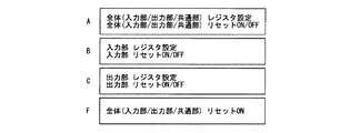
画像処理装置1がDRAM20に記憶された1フレームの静止画像のデータの画像処理を開始すると、まず、シーケンサ30は、処理100を行う。処理100においてシーケンサ30は、まず、処理110において、パイプラインを構成する全ての処理モジュール(入力DMAモジュール40、画像処理モジュールA50、画像処理モジュールB60、および出力DMAモジュール70)に対して、ブロック画像データを画像処理する際に必要なパラメータや入出力データ数などのレジスタ設定を行う。例えば、入力DMAモジュール40には、DRAM20から読み出して画像処理モジュールA50に出力する出力データ数が設定される。また、画像処理モジュールA50の入力部51には、入力DMAモジュール40から入力される入力データ数が設定され、出力部53には、ブロック画像データを画像処理する際に必要なパラメータや、画像処理データを次の画像処理モジュールB60に出力する際の出力データ数が設定される。
When the
続いて、シーケンサ30は、処理120において、全ての処理モジュールの動作の状態を初期化(リセット)する。この処理モジュールのリセットにおいてシーケンサ30は、入力DMAモジュール40および出力DMAモジュール70に対して、リセット信号を出力し、画像処理モジュールA50および画像処理モジュールB60に対して、共通リセット信号、入力部リセット信号、および出力部リセット信号を出力する。その後、シーケンサ30は、リセットを解除する。これにより、各処理モジュールは、それぞれの処理を開始することができる状態となる。このとき、画像処理モジュールA50は、入力DMAモジュール40に対してデータ要求信号を出力する。
Subsequently, in the
続いて、シーケンサ30は、処理130において、シーケンサ30は、入力DMAモジュール40および出力DMAモジュール70に対して、DMA開始トリガ信号を出力する。これにより、入力DMAモジュール40は、DMAによって、DRAM20からの最初(1つ目)のブロック画像データ(以下、「第1ブロック画像データ」という)を読み出し、画像処理モジュールA50に第1ブロック画像データを出力することができる状態となる。ここで、入力DMAモジュール40には、画像処理モジュールA50からデータ要求信号が入力されているため、入力DMAモジュール40がDRAM20から読み出した第1ブロック画像データは、画像処理モジュールA50に出力される。
Subsequently, in
そして、画像処理モジュールA50内の入力部51は、入力された第1ブロック画像データを、データバッファ52に書き込む。また、画像処理モジュールA50内の出力部53は、データバッファ52に記憶している第1ブロック画像データを読み出し、フィルタ処理部531によってフィルタ処理を行った画像処理データを、画像処理モジュールB60から入力されたデータ要求信号に応じて出力する。
Then, the
その後、画像処理モジュールA50は、入力部51によるデータバッファ52への第1ブロック画像データの書き込みが終了する、すなわち、処理110においてシーケンサ30によって設定された入力データ数の第1ブロック画像データをデータバッファ52に書き込んだとき、入力完了割込み信号をシーケンサ30に出力する。
Thereafter, the image processing module A50 finishes writing the first block image data to the
シーケンサ30は、画像処理モジュールA50から入力完了割込み信号が入力されると、処理200を行う。処理200においてシーケンサ30は、まず、処理210において、画像処理モジュールA50の入力部51に対して、入力DMAモジュール40から入力される次(2つ目)のブロック画像データ(以下、「第2ブロック画像データ」という)の入力データ数を設定する。
The
続いて、シーケンサ30は、処理220において、画像処理モジュールA50内の入力部51側の動作の状態をリセットする。この入力部51側のリセットにおいてシーケンサ30は、画像処理モジュールA50に対して、入力部リセット信号のみを出力する。その後、シーケンサ30は、画像処理モジュールA50に対するリセットを解除する。これにより、画像処理モジュールA50は、入力DMAモジュール40に対して第2ブロック画像データを要求するデータ要求信号を出力し、第2ブロック画像データのデータバッファ52への書き込みを開始する。
Subsequently, in the
なお、処理220においてシーケンサ30は、画像処理モジュールA50に対して共通リセット信号を出力していないため、画像処理モジュールA50内の調停部54およびデータバッファ領域決定部55はリセットされない。このため、画像処理モジュールA50内の入力部51が第2ブロック画像データをデータバッファ52に書き込む際には、第1ブロック画像データを最後に書き込んだデータバッファ52の記憶領域の次の記憶領域から、第2ブロック画像データの書き込みが開始される。これにより、入力部51が第2ブロック画像データをデータバッファ52に書き込む際に、出力部53がフィルタ処理を行って画像処理モジュールB60に出力していない第1ブロック画像データが上書きされてしまうことを回避することができる。
In the
その後、画像処理モジュールA50は、出力部53によるデータバッファ52からの第1ブロック画像データの読み出し、およびフィルタ処理部531によるフィルタ処理後の画像処理データの画像処理モジュールB60への出力が終了する、すなわち、処理110においてシーケンサ30によって設定された出力データ数のフィルタ処理後の画像処理データを出力したとき、出力完了割込み信号をシーケンサ30に出力する。
Thereafter, the image processing module A50 finishes reading the first block image data from the
シーケンサ30は、画像処理モジュールA50から出力完了割込み信号が入力されると、処理300を行う。処理300においてシーケンサ30は、まず、処理310において、画像処理モジュールA50の出力部53に対して、第2ブロック画像データを画像処理する際に必要なパラメータや、画像処理データを画像処理モジュールB60に出力する出力データ数を設定する。
The
続いて、シーケンサ30は、処理320において、画像処理モジュールA50内の出力部53側の動作の状態をリセットする。この出力部53側のリセットにおいてシーケンサ30は、画像処理モジュールA50に対して、出力部リセット信号のみを出力する。その後、シーケンサ30は、画像処理モジュールA50に対するリセットを解除する。これにより、画像処理モジュールA50は、データバッファ52に記憶している第2ブロック画像データに対するフィルタ処理後の画像処理データを、画像処理モジュールB60から入力されたデータ要求信号に応じて出力する。
Subsequently, in the
なお、処理320においてシーケンサ30は、画像処理モジュールA50に対して共通リセット信号を出力していないため、画像処理モジュールA50内の調停部54およびデータバッファ領域決定部55はリセットされない。このため、画像処理モジュールA50内の出力部53が第2ブロック画像データをデータバッファ52から読み出す際には、第1ブロック画像データを最後に読み出したデータバッファ52の記憶領域の次の記憶領域から、第2ブロック画像データの読み出しが開始される。これにより、出力部53が第2ブロック画像データをデータバッファ52から読み出す際に、データバッファ52に残っている第1ブロック画像データを読み出してフィルタ処理を行って画像処理モジュールB60に出力してしまうことを回避することができる。
In
その後、画像処理モジュールA50は、入力部51によるデータバッファ52への第2ブロック画像データの書き込みが終了する、すなわち、処理210においてシーケンサ30によって設定された入力データ数の第2ブロック画像データをデータバッファ52に書き込んだとき、入力完了割込み信号をシーケンサ30に出力する。
Thereafter, the image processing module A50 finishes writing the second block image data to the
シーケンサ30は、画像処理モジュールA50から入力完了割込み信号が入力されると、処理400を行う。処理400においてシーケンサ30は、処理200と同様に、入力DMAモジュール40から入力される次(3つ目)のブロック画像データ(以下、「第3ブロック画像データ」という)に対応した処理を行う。より具体的には、シーケンサ30は、処理410において、画像処理モジュールA50の入力部51に対して、第3ブロック画像データの入力データ数を設定する。そして、シーケンサ30は、処理420において、画像処理モジュールA50内の入力部51側の動作の状態をリセットおよびリセットの解除を行う。これにより、画像処理モジュールA50は、入力DMAモジュール40に対して第3ブロック画像データを要求するデータ要求信号を出力し、第3ブロック画像データのデータバッファ52への書き込みを開始する。
When the input completion interrupt signal is input from the image processing module A50, the
その後、画像処理モジュールA50は、出力部53によるデータバッファ52からの第2ブロック画像データの読み出し、およびフィルタ処理部531によるフィルタ処理後の画像処理データの画像処理モジュールB60への出力が終了する、すなわち、処理310においてシーケンサ30によって設定された出力データ数のフィルタ処理後の画像処理データを出力したとき、出力完了割込み信号をシーケンサ30に出力する。
Thereafter, the image processing module A50 finishes reading the second block image data from the
シーケンサ30は、画像処理モジュールA50から出力完了割込み信号が入力されると、処理500を行う。処理500においてシーケンサ30は、処理300と同様に、第3ブロック画像データに対応した処理を行う。より具体的には、シーケンサ30は、処理510において、画像処理モジュールA50の出力部53に対して、第3ブロック画像データを画像処理する際に必要なパラメータや、画像処理データを画像処理モジュールB60に出力する出力データ数を設定する。そして、シーケンサ30は、処理520において、画像処理モジュールA50内の出力部53側の動作の状態をリセットおよびリセットの解除を行う。これにより、画像処理モジュールA50は、データバッファ52に記憶している第3ブロック画像データに対するフィルタ処理後の画像処理データを、画像処理モジュールB60から入力されたデータ要求信号に応じて出力する。
The
以降、同様に、画像処理モジュールA50から割込み信号が入力される毎に、シーケンサ30は、入力された割込み信号に応じた処理を、画像処理装置1における1フレームの静止画像のデータのパイプライン処理が終了となるまで繰り返す。
Thereafter, similarly, every time an interrupt signal is input from the image
上記に述べたように、本実施形態の画像処理装置1に備えた画像処理モジュールA50では、入力DMAモジュール40からのブロック画像データの入力処理が完了したときの入力完了割込み信号と、画像処理モジュールB60へのフィルタ処理後の画像処理データの出力処理が完了ときの出力完了割込み信号とを、それぞれシーケンサ30に出力することができる。また、本実施形態の画像処理装置1に備えた画像処理モジュールB60では、画像処理モジュールA50からのフィルタ処理後の画像処理データの入力処理が完了したときの入力完了割込み信号と、出力DMAモジュール70への画像処理データの出力処理が完了ときの出力完了割込み信号とを、それぞれシーケンサ30に出力することができる。このように、画像処理モジュールA50および画像処理モジュールB60では、入力部51側の制御(入力リセットドメイン)と、出力部53側の制御(出力リセットドメイン)とを、分離することができる。これにより、画像処理モジュールA50および画像処理モジュールB60では、前の画像処理データの出力処理を実行している最中に、次のブロック画像データの入力処理を開始することができる。
As described above, in the image processing module A50 provided in the
このように、画像処理データの出力処理が完了する前に、次のブロック画像データの入力処理を開始することによって、画像処理モジュールA50および画像処理モジュールB60のそれぞれで、前の画像処理データの出力処理の完了から次の画像処理データの出力処理の開始までのロス時間を低減することができ、パイプライン処理の効率を向上させることができる。特に、ブロック画像データが入力されてからフィルタ処理後の画像処理データが出力されるまでの入出力の遅延時間が長い処理モジュール(例えば、以下に説明する歪補正処理モジュール)においては、高い効果を得ることができる。 As described above, before the output processing of the image processing data is completed, the input processing of the next block image data is started, so that each of the image processing module A50 and the image processing module B60 outputs the previous image processing data. Loss time from completion of processing to the start of output processing of the next image processing data can be reduced, and the efficiency of pipeline processing can be improved. In particular, in a processing module (for example, a distortion correction processing module described below) having a long input / output delay time from the input of block image data to the output of processed image data after filtering, it is highly effective. Can be obtained.
<適用例>
次に、画像処理モジュールA50を実際の画像処理に適用した場合の動作例について説明する。以下の説明においては、画像処理モジュールA50が、出力部53に備えたフィルタ処理部531によって歪補正処理を行う場合の例について説明する。図4は、本実施形態の画像処理モジュールA50において行う歪補正処理を説明する図である。
<Application example>
Next, an operation example when the image processing module A50 is applied to actual image processing will be described. In the following description, an example in which the image processing module A50 performs distortion correction processing by the filter processing unit 531 provided in the
一般的に歪補正処理においては、歪補正前の入力データが入力されてから、歪補正処理後の出力データが出力されるまでの入出力の遅延時間が長い。これは、歪補正処理においては、1つの補正後の出力データを得るために、複数の入力データが処理に用いられるからである。例えば、図4(a)に示すように、歪補正後の1つのラインXの出力データを得るためには、範囲Y分の入力データが必要である。このため、範囲Y分の入力データが処理モジュールに入力されるまで、補正後のラインXの出力データを出力することができない。このことにより、パイプライン処理における歪補正処理に起因するロス時間が長くなってしまう。 In general, in the distortion correction process, the input / output delay time from when input data before distortion correction is input to when output data after distortion correction is output is long. This is because in the distortion correction process, a plurality of input data are used for the process in order to obtain one corrected output data. For example, as shown in FIG. 4A, in order to obtain output data of one line X after distortion correction, input data for a range Y is necessary. For this reason, the corrected output data of the line X cannot be output until the input data for the range Y is input to the processing module. As a result, the loss time due to the distortion correction processing in the pipeline processing becomes long.
画像処理モジュールA50による歪補正処理においては、図4(b)に示すように、1フレームの静止画像のデータを複数のブロックに分割する。そして、分割したブロックに含まれるブロック画像データ毎に歪補正処理を行う。画像処理モジュールA50においては、上記に述べたように、前のブロック画像データに対応した画像処理データの出力処理、すなわち、歪補正処理を実行している最中に、次のブロック画像データの入力処理を行うことができる。より具体的には、最初のブロック1のブロック画像データに対して歪補正処理を行っている最中に、ブロック2のブロック画像データの入力を開始することができる。このため、画像処理モジュールA50では、ブロック1の歪補正処理における入出力の遅延時間以外の遅延時間を短縮することができ、パイプライン処理のロス時間を低減することができる。
In the distortion correction processing by the image processing module A50, as shown in FIG. 4B, the data of one frame of the still image is divided into a plurality of blocks. Then, distortion correction processing is performed for each block image data included in the divided blocks. In the image processing module A50, as described above, during the execution of the output processing of the image processing data corresponding to the previous block image data, that is, the distortion correction processing, the next block image data is input. Processing can be performed. More specifically, input of block image data of
<歪補正処理の方法例>
ここで、画像処理モジュールA50による歪補正処理の動作の説明に先立って、画像処理モジュールA50における歪補正処理の処理方法および各構成要素の構成について説明する。まず、画像処理モジュールA50における歪補正処理の方法について説明する。図5は、本実施形態の画像処理モジュールA50における歪補正処理方法の一例を説明する図である。歪補正処理に画像処理モジュールA50を適用した場合の本適用例においては、画像処理モジュールA50内のフィルタ処理部531は、図5(a)に示したような、1フレームの静止画像のデータを水平方向に複数のブロック(以下、「ブロックライン」という)に分割したブロック画像データ毎に歪補正処理を行う。そして、フィルタ処理部531は、静止画像の上(ブロックライン1)から順次歪補正処理を行うものとする。
<Example of distortion correction processing>
Here, prior to the description of the operation of the distortion correction processing by the image processing module A50, the processing method of the distortion correction processing in the image processing module A50 and the configuration of each component will be described. First, a method of distortion correction processing in the image processing module A50 will be described. FIG. 5 is a diagram for explaining an example of the distortion correction processing method in the image processing module A50 of the present embodiment. In the present application example in which the image processing module A50 is applied to the distortion correction processing, the filter processing unit 531 in the image processing module A50 converts one frame of still image data as shown in FIG. Distortion correction processing is performed for each block image data divided into a plurality of blocks (hereinafter referred to as “block lines”) in the horizontal direction. The filter processing unit 531 sequentially performs distortion correction processing from the top of the still image (block line 1).
より具体的には、フィルタ処理部531は、まず、図5(b)に示すように、ブロックライン1の歪補正処理を行う。そして、ブロックライン1の歪補正処理が終了した後に、図5(c)および図5(d)に示すように、ブロックライン2、続いてブロックライン3というように、順次、歪補正処理を行っていく。
More specifically, the filter processing unit 531 first performs distortion correction processing on the
なお、フィルタ処理部531が歪補正処理を行う際に静止画像のデータを分割する方法は、図5に示した水平方向のみの分割に限定されるものではなく、例えば、図4(a)に示したように、水平方向に加えて垂直方向にも分割し、分割したそれぞれのブロック毎に歪補正処理を行う構成とすることもできる。 Note that the method of dividing still image data when the filter processing unit 531 performs distortion correction processing is not limited to the horizontal division shown in FIG. 5. For example, the method shown in FIG. As shown in the figure, it is also possible to divide in the vertical direction in addition to the horizontal direction and perform a distortion correction process for each of the divided blocks.
<データバッファの構成例>
続いて、本適用例におけるデータバッファ52の構成について説明する。図6および図7は、本実施形態の画像処理モジュールA50に備えたデータバッファ52の構成例および動作例を説明する図である。本適用例の画像処理モジュールA50に備えたデータバッファ52は、図6(a)に示したように、ブロックラインの垂直方向の幅を1ラインとし、ブロックラインの水平方向に16ライン分の記憶領域(領域1〜領域16)で構成されているものとする。
<Configuration example of data buffer>
Next, the configuration of the
そして、上記に述べたように、ブロックライン1→ブロックライン2→ブロックライン3というように、順次、歪補正処理を行っていく(図6(b)参照)。このとき、画像処理モジュールA50には、入力DMAモジュール40から、図6(c)に示したような順番でブロック画像データが入力される。より具体的には、最初に、ブロックライン1の1ライン目のブロック画像データが入力され、続いて、ブロックライン1の2ライン目のブロック画像データが入力される。その後、ブロックライン1の20ライン目のブロック画像データが入力されると、続いて、ブロックライン2の1ライン目のブロック画像データが入力される。以降、同様に、ブロックライン2の2ライン目のブロック画像データ・・・ブロックライン2の20ライン目のブロック画像データ、ブロックライン3の1ライン目のブロック画像データ・・・ブロックライン3の20ライン目のブロック画像データというように、入力DMAモジュール40から順次ブロック画像データが入力される。
Then, as described above, distortion correction processing is sequentially performed in the order of
なお、以下の説明においては、画像処理モジュールA50に入力されるブロック画像データに対して、ブロックライン、およびブロックライン内のライン数を区別するための符号を付与して説明する。例えば、ブロックライン1の1ライン目のブロック画像データは、「ブロック画像データIBL1−1」という。また、例えば、ブロックライン3の20ライン目のブロック画像データは、「ブロック画像データIBL3−20」という。また、フィルタ処理部531によって歪み補正処理がされた後に、画像処理モジュールA50から出力される歪補正処理後の画像処理データに対しても、同様に、ブロックライン、およびブロックライン内のライン数を区別するための符号を付与して説明する。例えば、歪補正処理後の画像処理データにおいて、ブロックライン1の1ライン目の画像処理データは、「画像処理データOBL1−1」という。また、例えば、ブロックライン3の16ライン目の画像処理データは、「画像処理データOBL3−16」という。
In the following description, the block image data input to the image processing module A50 will be described with a block line and a code for distinguishing the number of lines in the block line. For example, the block image data of the first line of the
図7は、入力DMAモジュール40から本適用例の画像処理モジュールA50に20ラインのブロック画像データが入力され、本適用例の画像処理モジュールA50から画像処理モジュールB60に16ラインの歪補正処理後の画像処理データが出力される場合のパイプライン処理のタイミングを示している。
In FIG. 7, 20 lines of block image data are input from the
<データバッファへのデータ書き込みの例>
続いて、本適用例においてブロック画像データをデータバッファ52に書き込む動作について説明する。図8は、本実施形態の画像処理モジュールA50に備えたデータバッファ52にブロック画像データを書き込む動作例を説明する図である。
<Example of writing data to the data buffer>
Next, an operation of writing block image data in the
本適用例の画像処理モジュールA50内に備えたデータバッファ52の構成は、図6(a)に示したように、16ライン分の記憶領域で構成されている。すなわち、データバッファ52の記憶領域は、領域1〜領域16のみである。このため、画像処理モジュールA50では、データバッファ52が、領域1と領域16とを仮想的にリング状につなげられたリングバッファの形式であるものとして、入力部51が、入力DMAモジュール40から入力されたブロック画像データの書き込みを制御する。ブロック画像データを書き込むデータバッファ52の領域は、データバッファ領域決定部55によって決定される。
As shown in FIG. 6A, the configuration of the
図8では、ブロックライン1→ブロックライン2→ブロックライン3というように、順次、ブロック画像データをデータバッファ52に書き込む場合において、各ブロックラインが20ラインであったときに、それぞれのブロック画像データが記憶されるデータバッファ52の記憶領域を示している。なお、図8においては、説明を容易にするため、データバッファ52の記憶領域(領域1〜領域16)の状態を、時系列に4回並べて表している。
In FIG. 8, when sequentially writing block image data to the
より具体的には、画像処理装置1におけるパイプライン処理が開始されると、データバッファ領域決定部55は、データバッファ52の領域1〜領域16を、ブロック画像データIBL1−1〜ブロック画像データIBL1−16を書き込む記憶領域として決定する(図8(a)参照)。また、データバッファ領域決定部55は、領域1〜領域16に記憶しているブロック画像データIBL1−1〜ブロック画像データIBL1−16が、フィルタ処理部531による歪補正処理に使用され、調停部54によって空き領域であると判断される毎に、空き領域であると判断されたデータバッファ52の領域1〜領域16を、順次、次のブロック画像データを書き込む記憶領域として決定する(図8(b)〜図8(d)参照)。
More specifically, when pipeline processing in the
図8(b)においては、データバッファ52の領域1〜領域4が、ブロック画像データIBL1−17〜ブロック画像データIBL1−20を書き込む記憶領域として決定され、データバッファ52の領域5〜領域16が、ブロック画像データIBL2−1〜ブロック画像データIBL1−12を書き込む記憶領域として決定された場合を表している。なお、入力部51は、データバッファ52の領域4へのブロック画像データIBL1−20の書き込みが完了したときに、入力完了割込み信号を、シーケンサ30に出力する。
In FIG. 8B,
また、図8(c)においては、データバッファ52の領域1〜領域8が、ブロック画像データIBL2−13〜ブロック画像データIBL2−20を書き込む記憶領域として決定され、データバッファ52の領域9〜領域16が、ブロック画像データIBL3−1〜ブロック画像データIBL1−8を書き込む記憶領域として決定された場合を表している。なお、入力部51は、データバッファ52の領域8へのブロック画像データIBL2−20の書き込みが完了したときに、入力完了割込み信号を、シーケンサ30に出力する。
In FIG. 8C,
また、図8(d)においては、データバッファ52の領域1〜領域12が、ブロック画像データIBL3−9〜ブロック画像データIBL3−20を書き込む記憶領域として決定された場合を表している。なお、入力部51は、データバッファ52の領域12へのブロック画像データIBL3−20の書き込みが完了したときに、入力完了割込み信号を、シーケンサ30に出力する。
FIG. 8D illustrates a case where the
<データバッファからのデータ読み出しの例>
続いて、本適用例においてデータバッファ52に記憶されているブロック画像データを読み出す動作について説明する。図9は、本実施形態の画像処理モジュールA50に備えたデータバッファ52からブロック画像データを読み出す動作例を説明する図である。
<Example of reading data from data buffer>
Next, an operation of reading block image data stored in the
データバッファ52に記憶されているブロック画像データを読み出す際には、出力部53が、フィルタ処理部531による歪補正処理を行うために必要なブロック画像データがデータバッファ52内に記憶されているか否かを判断し、必要なブロック画像データが記憶されていると判断された場合に、データバッファ52の読み出しを行う。歪補正処理を行うために必要なブロック画像データがデータバッファ52内に記憶されているか否かの判断は、調停部54から出力される有効データ量情報に基づいて行われる。
When the block image data stored in the
図9では、データバッファ52のそれぞれの記憶領域に記憶されている20ラインのブロック画像データを用いて歪み補正処理を行い、16ラインの画像処理データを出力する場合を示している。なお、図9においては、歪補正処理に関係するデータバッファ52の領域のみにブロック画像データの符号を示している。
FIG. 9 shows a case where distortion correction processing is performed using 20 lines of block image data stored in the respective storage areas of the
ここで、図9を参照して、データバッファ52に記憶されているブロック画像データを読み出して、歪補正処理後の画像処理データを生成する場合の動作例について説明する。まず、図9(a)を参照して、画像処理データOBL1−1を出力するために、ブロック画像データIBL1−1〜ブロック画像データIBL1−4が必要である場合について説明する。出力部53は、調停部54から出力される有効データ量情報が、データバッファ52の領域1〜領域4に記憶されているブロック画像データが有効なデータであるか否かを判断する。そして、データバッファ52の領域1〜領域4に記憶されているブロック画像データが有効なデータである場合、出力部53は、データバッファ52の領域1〜領域4に記憶されているブロック画像データを読み出し、フィルタ処理部531による歪補正処理後の画像処理データOBL1−1を出力する。
Here, with reference to FIG. 9, an example of operation when the block image data stored in the
また、出力部53は、次の画像処理データOBL1−2を出力するために必要としないデータバッファ52の記憶領域に対応するリード完了通知を、調停部54に出力する。調停部54は、リード完了通知が入力されたデータバッファ52の記憶領域を、空き領域とする。図9(a)においては、画像処理データOBL1−1を出力するために必要であったが、画像処理データOBL1−2を出力するためには必要でないブロック画像データIBL1−1を記憶しているデータバッファ52の領域1に対応するリード完了通知を出力し、領域1を空き領域とする場合を示している。この空き領域となったデータバッファ52の記憶領域には、入力部51によって、順次、次に入力されたブロック画像データが書き込まれる。
Further, the
以降、出力部53は、画像処理データOBL1−2〜画像処理データOBL1−16を出力するために必要なデータバッファ52の記憶領域を、調停部54から出力される有効データ量情報に基づいて順次判断し、フィルタ処理部531による歪補正処理後の画像処理データOBL1−2〜画像処理データOBL1−16を順次出力する。また、出力部53は、画像処理データを出力した後に、次の画像処理データを出力するために必要としないデータバッファ52の記憶領域に対応するリード完了通知を、調停部54に順次出力する。そして、調停部54は、入力されたリード完了通知に基づいて、データバッファ52の記憶領域を、順次空き領域とし、空き領域となったデータバッファ52の記憶領域には、入力部51によって、順次、次に入力されたブロック画像データが書き込まれる。
Thereafter, the
図9(b)においては、画像処理データOBL1−2を出力するために、ブロック画像データIBL1−2〜ブロック画像データIBL1−5が必要である場合を示している。図9(c)においては、画像処理データOBL1−16を出力するために、ブロック画像データIBL1−16〜ブロック画像データIBL1−20が必要である場合を示している。図9(c)においてブロックライン1における画像処理データOBL1−16の出力が完了する。これにより、ブロック画像データIBL1−16〜ブロック画像データIBL1−20は、次のブロックライン2に対応した画像処理データOBL1−1を出力するために必要ではないため、出力部53は、データバッファ52の領域1〜領域4および領域16に対応するリード完了通知を、調停部54に出力する。なお、出力部53は、次の画像処理モジュールB60への画像処理データOBL1−16の出力が完了したときに、出力完了割込み信号を、シーケンサ30に出力する。
FIG. 9B shows a case where block image data IBL1-2 to block image data IBL1-5 are necessary to output the image processing data OBL1-2. FIG. 9C shows a case where block image data IBL1-16 to block image data IBL1-20 are necessary to output the image processing data OBL1-16. In FIG. 9C, the output of the image processing data OBL1-16 in the
そして、出力部53は、画像処理データOBL2−1を出力するために必要なブロック画像データIBL2−1〜ブロック画像データIBL2−5が、データバッファ52の領域5〜領域9に記憶されているか否かを、調停部54から出力される有効データ量情報に基づいて判断する。そして、データバッファ52の領域5〜領域9に記憶されているブロック画像データが有効なデータである場合、出力部53は、データバッファ52の領域5〜領域9に記憶されているブロック画像データを読み出し、フィルタ処理部531による歪補正処理後の画像処理データOBL2−1を出力する(図9(d)参照)。
Then, the
以降、出力部53は、画像処理データを出力するために必要なデータバッファ52の記憶領域を、調停部54から出力される有効データ量情報に基づいて順次判断し、データバッファ52の記憶領域に記憶されているブロック画像データが有効なデータである場合に、ブロック画像データの読み出しと、画像処理データの出力とを順次行う。また、出力部53は、画像処理データを出力した後に、次の画像処理データを出力するために必要としないデータバッファ52の記憶領域に対応するリード完了通知を、調停部54に順次出力して、データバッファ52の記憶領域を順次空き領域とする。
Thereafter, the
<動作例>
続いて、本適用例の画像処理モジュールA50における歪み補正処理の動作について説明する。図10および図11は、本実施形態の画像処理モジュールA50におけるパイプライン処理のタイミングおよび制御内容の一例を説明する図である。図10および図11においては、説明を容易にするため、図4〜図9を用いて説明した本適用例の画像処理モジュールA50の構成を簡略化した場合の例を示している。図10および図11の説明を行うための変更点は以下である。まず、1フレームの静止画像のデータを、2つのブロックラインに分割する。また、データバッファ52は8ライン分の記憶領域(領域1〜領域8)とする。また、入力部51には、12ラインのブロック画像データが入力され、出力部53からは、11ラインの画像処理データが出力されるものとする。なお、ブロック画像データおよび画像処理データには、ブロックライン、およびブロックライン内のライン数を区別するための符号を、上記と同様に付与して説明する。なお、画像処理モジュールA50のパイプライン処理のタイミングに関しては図10を参照し、このときのシーケンサ30による画像処理モジュールA50の制御内容に関しては図11を参照して説明を行う。
<Operation example>
Subsequently, an operation of distortion correction processing in the image processing module A50 of the application example will be described. 10 and 11 are diagrams for explaining an example of the pipeline processing timing and control contents in the image processing module A50 of the present embodiment. 10 and 11 show examples in which the configuration of the image processing module A50 of the application example described with reference to FIGS. 4 to 9 is simplified for easy explanation. The changes for explaining FIG. 10 and FIG. 11 are as follows. First, one frame of still image data is divided into two block lines. The
画像処理装置1がDRAM20に記憶された1フレームの静止画像のデータの画像処理を開始すると、まず、シーケンサ30は、処理100を行う。処理100においては、図3で説明した処理100と同様に、シーケンサ30が、パイプラインを構成する全ての処理モジュールに対するパラメータや入出力データ数などのレジスタ設定を行い、全ての処理モジュールの動作状態の初期化(リセット)を行う。これにより、画像処理モジュールA50は、歪み補正処理を開始することができる状態となり、調停部54が出力するバッファ空き量情報は、データバッファ52の記憶領域が全て空き領域であることを表す情報に初期化され、有効データ量情報は、データバッファ52の全ての記憶領域に有効なデータが記憶されていないことを表す情報に初期化される。また、データバッファ領域決定部55が出力するライト領域情報に含まれるライト先頭バッファ領域と、リード領域情報に含まれるリード先頭バッファ領域とは、データバッファ52の領域1となる。また、入力部51は、入力DMAモジュール40に対してブロック画像データのデータ要求信号を出力する。なお、以下の説明においては、調停部54とデータバッファ領域決定部55とを合わせて、「共通部」ともいう。
When the
そして、シーケンサ30は、入力DMAモジュール40および出力DMAモジュール70に対するDMA開始トリガ信号を出力する。これにより、入力DMAモジュール40は、DMAによって、DRAM20からのブロック画像データIBL1−1を読み出し、読み出したブロック画像データIBL1−1を、画像処理モジュールA50に出力する(タイミングt1)。入力DMAモジュール40からブロック画像データIBL1−1が入力されると、入力部51は、入力されたブロック画像データIBL1−1をデータバッファ52の領域1に書き込む。また、入力部51は、ブロック画像データIBL1−1のデータバッファ52の領域1への書き込みが完了すると、ライト完了通知を調停部54に出力する。調停部54は、入力部51からライト完了通知が入力されると、領域1の状態を表すステータスを、「データあり」の状態に変更する(タイミングt2)。
Then, the
以降、入力DMAモジュール40からブロック画像データが入力される毎に、入力部51は、入力されたブロック画像データをデータバッファ52の対応する記憶領域に書き込み、対応するライト完了通知を調停部54に出力する。そして、調停部54は、ライト完了通知が入力されたデータバッファ52に対応する領域のステータスを、「データあり」の状態に変更していく。
Thereafter, every time block image data is input from the
その後、調停部54は、歪補正処理後の画像処理データを生成するために必要なブロック画像データがデータバッファ52内に記憶されたときに、有効データ量情報をデータバッファ52内の記憶領域に有効なデータが記憶されていることを表す状態に変更する。図10では、画像処理データOBL1−1を出力するために、ブロック画像データIBL1−1〜ブロック画像データIBL1−3が必要であり、ブロック画像データIBL1−3が、データバッファ52の領域3に書き込まれたときに有効データ量情報を変更する場合を示している。出力部53は、調停部54からの有効データ量情報が入力されると、データバッファ52の領域1〜領域3から、ブロック画像データIBL1−1からブロック画像データIBL1−3を読み出し、フィルタ処理部531によって歪み補正処理を行って、画像処理データOBL1−1を出力する(タイミングt3)。
After that, the
また、出力部53は、画像処理データOBL1−1を出力すると、次の画像処理データOBL1−2を出力するためには必要でないブロック画像データIBL1−1を記憶しているデータバッファ52の領域1に対応するリード完了通知を調停部54に出力する。調停部54は、出力部53からリード完了通知が入力されると、ブロック画像データIBL1−1を記憶していたデータバッファ52の領域1のステータスを、「データなし」の状態、すなわち、空き領域の状態に変更する(タイミングt4)。
Further, when the
以降、出力部53は、調停部54から入力される有効データ量情報に基づいて、データバッファ52の対応する記憶領域からブロック画像データを読み出し、フィルタ処理部531によって歪み補正処理を行った画像処理データを出力する。
Thereafter, the
その後、図10のタイミングt5〜タイミングt6の期間は、画像処理データOBL1−3を出力するために必要なブロック画像データIBL1−3〜ブロック画像データIBL1−6がデータバッファ52の対応する記憶領域に書き込まれていないため、有効データ量情報が有効なデータが記憶されていないことを表す状態となっており、出力部53の処理が待たされている状態を示している。出力部53は、ブロック画像データIBL1−3〜ブロック画像データIBL1−6がデータバッファ52に書き込まれた後に、ブロック画像データIBL1−3〜ブロック画像データIBL1−6のデータバッファ52からの読み出しを再開し、フィルタ処理部531によって歪み補正処理を行った画像処理データOBL1−3を出力する。
Thereafter, during the period from timing t5 to timing t6 in FIG. 10, block image data IBL1-3 to block image data IBL1-6 necessary for outputting the image processing data OBL1-3 are stored in the corresponding storage areas of the
また、図10のタイミングt7は、データバッファ52の領域8に書き込むブロック画像データIBL1−8が入力DMAモジュール40から入力された後、ブロック画像データIBL1−9が入力されたタイミングである。このとき、調停部54におけるデータバッファ52の領域1のステータスは、「データなし」の状態であるため、入力部51は、引き続きブロック画像データIBL1−9をデータバッファ52の領域1に書き込む。
10 is a timing at which the block image data IBL1-9 is input after the block image data IBL1-8 to be written to the area 8 of the
その後、入力部51は、ブロックライン1の最後のブロック画像データIBL1−12を、データバッファ52の領域4への書き込みが完了すると、ライト完了通知を調停部54に出力するとともに、入力完了割込み信号をシーケンサ30に出力する(タイミングt8)。
After that, when the writing of the last block image data IBL1-12 of the
シーケンサ30は、画像処理モジュールA50から入力完了割込み信号が入力されると、処理200を行う。処理200においては、図3で説明した処理200と同様に、シーケンサ30が、画像処理モジュールA50の入力部51に対して、入力DMAモジュール40から入力されるブロックライン2のブロック画像データの入力データ数の設定を行い、入力部51側の動作の状態のリセットを行うための入力部リセット信号を出力する(タイミングt9)。これにより、画像処理モジュールA50は、ブロックライン2のブロック画像データの入力を開始することができる状態となり、入力部51は、入力DMAモジュール40に対してブロックライン2のブロック画像データのデータ要求信号を出力する。なお、共通部(調停部54およびデータバッファ領域決定部55)は、リセットされないため、入力部51は、入力DMAモジュール40から入力されたブロックライン2のブロック画像データをデータバッファ52の領域5から順次書き込みを行う。このとき、データバッファ領域決定部55が出力するライト領域情報に含まれるライト先頭バッファ領域は、データバッファ52の領域5となる。
The
その後、図10のタイミングt10〜タイミングt11の期間は、画像処理データOBL1−11を出力するために、出力部53がデータバッファ52の領域8に記憶されているブロック画像データIBL1−8が使用されている、すなわち、出力部53によるブロック画像データIBL1−8の読み出しが完了していないため、入力部51によるデータバッファ52の領域8へのブロック画像データIBL2−4の書き込みが待たされている状態を示している。そして、出力部53は、画像処理データOBL1−11の出力が完了すると、リード完了通知を調停部54に出力するとともに、出力完了割込み信号をシーケンサ30に出力する(タイミングt11)。入力部51は、出力部53によるブロック画像データIBL1−8の読み出しが完了した後に、データバッファ52の領域8へのブロック画像データIBL2−4の書き込みを再開する。
Thereafter, during the period from the timing t10 to the timing t11 in FIG. 10, the block image data IBL1-8 stored in the area 8 of the
シーケンサ30は、画像処理モジュールA50から出力完了割込み信号が入力されると、処理300を行う。処理300においては、図3で説明した処理300と同様に、シーケンサ30が、画像処理モジュールA50の出力部53に対して、ブロックライン2のブロック画像データに対して歪み補正処理を行うために必要なパラメータや、画像処理データの出力データ数の設定を行い、出力部53側の動作の状態のリセットを行うための出力部リセット信号を出力する(タイミングt12)。これにより、画像処理モジュールA50は、ブロックライン2のブロック画像データに対する歪み補正処理を開始できる状態となり、出力部53は、データバッファ52に記憶しているブロックライン2のブロック画像データの読み出しと、画像処理データの出力とを開始する。なお、共通部(調停部54およびデータバッファ領域決定部55)は、リセットされないため、出力部53は、データバッファ52の領域5からブロックライン2のブロック画像データの読み出しを順次行う。このとき、データバッファ領域決定部55が出力するリード領域情報に含まれるリード先頭バッファ領域は、データバッファ52の領域5となる。
The
その後、入力部51は、ブロックライン2の最後のブロック画像データIBL2−12を、データバッファ52の領域8への書き込みが完了すると、ライト完了通知を調停部54に出力するとともに、入力完了割込み信号をシーケンサ30に出力する(タイミングt13)。なお、タイミングt13においてシーケンサ30に入力完了割込み信号が入力されるが、シーケンサ30は、画像処理モジュールA50に対して何も行わない。これは、タイミングt13において入力された入力完了割込み信号は、全てのブロックラインのブロック画像データが画像処理モジュールA50に入力されたことを表しているのみであり、画像処理モジュールA50に次のブロックラインに対する設定をする必要がないからである。
After that, when the writing of the last block image data IBL2-12 of the
その後、出力部53は、画像処理データOBL2−11の出力が完了すると、リード完了通知を調停部54に出力するとともに、出力完了割込み信号をシーケンサ30に出力する(タイミングt14)。
Thereafter, when the output of the image processing data OBL2-11 is completed, the
シーケンサ30は、画像処理モジュールA50から出力完了割込み信号が入力されると、処理600を行う。処理600においてシーケンサ30は、画像処理モジュールA50の全体をリセットし、画像処理モジュールA50における処理を完了する。より具体的には、シーケンサは、共通リセット信号、入力部リセット信号、および出力部リセット信号を画像処理モジュールA50に出力して、画像処理モジュールA50の処理を完了する。
The
上記に述べたように、本適用例の画像処理モジュールA50では、入力DMAモジュール40からのブロック画像データの入力処理が完了したときの入力完了割込み信号と、歪み補正処理を行った画像処理データの出力処理が完了ときの出力完了割込み信号とを、それぞれシーケンサ30に出力することができる。また、データバッファ52の使用状態に応じて、ブロック画像データのデータバッファ52への書き込み制御、およびデータバッファ52からのブロック画像データの読み出し制御を調停することができる。
As described above, in the image processing module A50 of this application example, the input completion interrupt signal when the input processing of the block image data from the
このようにして、本適用例の画像処理モジュールA50では、前の画像処理データの出力処理を実行している最中に、次のブロック画像データの入力処理を開始することができる。図12は、従来の処理モジュールにおけるパイプライン処理と、本実施形態の処理モジュールにおけるパイプライン処理とを比較した図である。なお、図12(a)は、従来の処理モジュールにおけるパイプライン処理を示し、図12(b)は、本実施形態の処理モジュールにおけるパイプライン処理を示している。従来の処理モジュールでは、図12(a)に示したように、前に入力されたデータに対応した出力が完了してから次に入力されたデータに対応した出力が開始されるまでの時間が、ロス時間となっている。これに対して、本適用例の画像処理モジュールA50(本実施形態の処理モジュール)では、図12(b)に示したように、画像処理モジュールA50における入出力の遅延時間は変わらないが、画像処理データの出力処理が完了する前に、次のブロック画像データの入力処理を開始することができるため、前の画像処理データの出力処理の完了から次の画像処理データの出力処理の開始までのロス時間を、従来の処理モジュールよりも低減することができる。これにより、特に、ブロック画像データが入力されてから画像処理データが出力されるまでの入出力の遅延時間が長い処理モジュールにおいて、パイプライン処理の効率を向上させることができる。 In this way, in the image processing module A50 of this application example, the input processing of the next block image data can be started while the output processing of the previous image processing data is being executed. FIG. 12 is a diagram comparing the pipeline processing in the conventional processing module and the pipeline processing in the processing module of the present embodiment. FIG. 12A shows the pipeline processing in the conventional processing module, and FIG. 12B shows the pipeline processing in the processing module of the present embodiment. In the conventional processing module, as shown in FIG. 12A, the time from the completion of the output corresponding to the previously input data to the start of the output corresponding to the next input data is started. , Lost time. On the other hand, in the image processing module A50 of this application example (the processing module of the present embodiment), as shown in FIG. 12B, the input / output delay time in the image processing module A50 is not changed, but the image Since the input processing of the next block image data can be started before the output processing of the processing data is completed, from the completion of the output processing of the previous image processing data to the start of the output processing of the next image processing data Loss time can be reduced compared to conventional processing modules. Thereby, it is possible to improve the efficiency of pipeline processing, particularly in a processing module having a long input / output delay time from the input of block image data to the output of image processing data.
<データバッファのバッファサイズ決定方法の例>
なお、図10に示したパイプライン処理のタイミングにおいては、出力部53の処理が待たされている期間(タイミングt5〜タイミングt6)、および入力部51によるデータバッファ52へのブロック画像データの書き込みが待たされている期間(タイミングt10〜タイミングt11)が存在している。このように、処理が待たされる時間も処理モジュールの入出力の遅延時間に影響し、パイプライン処理におけるロス時間となってしまう。このような処理モジュール内の処理が待たされることによるロス時間は、データバッファ52のバッファサイズを最適化することによって、低減することもできる。
<Example of data buffer size determination method>
Note that, at the timing of the pipeline processing shown in FIG. 10, the period during which the processing of the
ここで、本適用例におけるデータバッファ52のバッファサイズを決定する方法について説明する。図13は、本実施形態の画像処理モジュールA50に備えるデータバッファ52の記憶領域の数(バッファサイズ)を決定する方法を説明する図である。本適用例の画像処理モジュールA50においては、歪量が最も大きいブロックラインの最後のラインの画像処理データを出力するために必要なブロック画像データの数と、その次のブロックラインの最初のラインの画像処理データを出力するために必要なブロック画像データの数とに基づいて決定することができる。
Here, a method for determining the buffer size of the
例えば、ブロックライン1の最後のラインの画像処理データ(例えば、図9(c)に示した画像処理データOBL1−16)を出力するために必要なブロック画像データの数が図13に示した範囲(糊代)Mであり、次のブロックライン2の最初のラインの画像処理データ(例えば、図9(d)に示した画像処理データOBL2−1)を出力するために必要なブロック画像データの数が図13に示した範囲(糊代)Nであると仮定する。この場合において、出力部53側から考えると、画像処理データOBL1−16を出力した直後に画像処理データOBL2−1を出力することができれば、画像処理モジュールA50内の処理が待たされる時間、すなわちロス時間を最小にすることができる。すなわち、画像処理データOBL1−16の歪み補正処理を行っている間に、画像処理データOBL2−1を出力するために必要なブロック画像データがデータバッファ52に書き込まれていれば、ロス時間を最小にすることができる。これは、データバッファ52に、画像処理データOBL1−16を出力するために使用する範囲Mのブロック画像データと、画像処理データOBL2−1を出力するために使用する範囲Nのブロック画像データとが、画像処理データOBL1−16の歪み補正処理を行っている間、格納されている必要があることを表している。このため、範囲Mと範囲Nとを合計した数を、データバッファ52のバッファサイズに決定する。
For example, the number of block image data necessary to output the image processing data of the last line of the block line 1 (for example, the image processing data OBL1-16 shown in FIG. 9C) is within the range shown in FIG. (Adhesive margin) M, which is the block image data necessary for outputting the image processing data of the first line of the next block line 2 (for example, the image processing data OBL2-1 shown in FIG. 9D). It is assumed that the number is in the range (glue margin) N shown in FIG. In this case, considering from the
このようにして、フィルタ処理部531によって行うフィルタ処理に必要なブロック画像データの数に応じてデータバッファ52のバッファサイズを決定することにより、最適な回路規模で、ロス時間を低減することができる。なお、本適用例では、歪み補正処理に必要なブロック画像データの数に基づいてバッファサイズを決定する方法を説明したが、バッファサイズの決定方法は、フィルタ処理部531が行うフィルタ処理の種類によって異なる。例えば、フィルタ処理部531によるフィルタ処理が、ローパスフィルタ処理であれば、フィルタのタップ数(フィルタサイズ)に応じた必要なデータ数に基づいてバッファサイズを決定する。
In this way, by determining the buffer size of the
上記に述べたとおり、本発明を実施するための形態によれば、パイプラインを構成するそれぞれの処理モジュールの内、入出力の遅延時間に起因する時間的なロスが大きい処理モジュールにおけるリセットの制御単位を、当該処理モジュールの入力側と出力側とで分離する。そして、処理モジュールの入力側または出力側の処理が完了する毎に、処理が完了したことを表す信号をそれぞれ出力するように構成する。より具体的には、例えば、画像処理モジュールA50においては、入力部51側と出力部53側とに分離し、入力完了割込み信号と出力完了割込み信号とを、それぞれ出力する。これにより、処理モジュールの入力側または出力側のいずれか一方の処理が完了したときに、他方の処理が完了していなくとも、次の処理を開始させることができ、当該処理モジュールにおける入出力の遅延時間に起因するロス時間を短くすることができる。これにより、パイプライン処理におけるロス時間を低減することができる。
As described above, according to the mode for carrying out the present invention, among the processing modules constituting the pipeline, control of reset in the processing module having a large time loss due to the input / output delay time. The unit is separated on the input side and output side of the processing module. Each time processing on the input side or output side of the processing module is completed, a signal indicating that the processing is completed is output. More specifically, for example, in the image processing module A50, the
なお、本実施形態においては、歪み補正処理を行う画像処理モジュールに適用した場合について説明したが、適用することができる画像処理モジュールは、本発明を実施するための形態に限定されるものではない。例えば、ローパスフィルタ処理、ノイズ低減フィルタ処理、画像リサイズ処理など、大きなフィルタ処理を行う様々な画像処理モジュールに適用することができる。 In the present embodiment, the case where the present invention is applied to an image processing module that performs distortion correction processing has been described. However, the image processing module that can be applied is not limited to the embodiment for carrying out the present invention. . For example, the present invention can be applied to various image processing modules that perform large filter processing such as low-pass filter processing, noise reduction filter processing, and image resizing processing.
また、本実施形態においては、入力DMAモジュール40、画像処理モジュールA50、画像処理モジュールB60、および出力DMAモジュール70によってパイプラインを構成した場合の一例について説明したが、パイプラインを構成する処理モジュールは、本発明を実施するための形態に限定されるものではない。
In this embodiment, an example in which a pipeline is configured by the
なお、特許文献1には、ロス時間を短縮するために、2つのバッファを用いる方法も開示されている(図17(a)参照)。2つのバッファを使用する場合には、図17(b)に示したように、一方のバッファ(例えば、バッファA)に画像データを書き込んでいる(Writeしている)ときには、他方のバッファ(例えば、バッファB)に書き込まれている画像データを読み出して(Readして)出力するように、切り替え制御を行っている。しかしながら、フィルタ処理を行う処理モジュールにおいては、フィルタ処理を行うために大容量のバッファを使用することが考えられるため、1つの処理モジュール内に大容量のバッファを2つ備えると、処理モジュールの回路規模が大きくなってしまう。本実施形態においては、バッファを仮想的にリング状につなげることによって、1つのバッファのみでフィルタ処理を行うことができる。このため、従来の2つのバッファを用いた処理モジュールよりも、小さい回路規模でフィルタ処理を行う処理モジュールを実現することができる。
以上、本発明の実施形態について、図面を参照して説明してきたが、具体的な構成はこの実施形態に限定されるものではなく、本発明の趣旨を逸脱しない範囲においての種々の変更も含まれる。 The embodiment of the present invention has been described above with reference to the drawings. However, the specific configuration is not limited to this embodiment, and includes various modifications within the scope of the present invention. It is.
1・・・画像処理装置
10・・・DMAバス
20・・・DRAM
30・・・シーケンサ(画像処理装置)
40・・・入力DMAモジュール
50・・・画像処理モジュールA(データ処理装置)
51・・・入力部(データ書き込み制御部)
52・・・データバッファ(バッファ部)
53・・・出力部(データ読み出し制御部)
531・・・フィルタ処理部(データ読み出し制御部、フィルタ処理部)
54・・・調停部(バッファ領域決定部)
55・・・データバッファ領域決定部(バッファ領域決定部)
60・・・画像処理モジュールB(データ処理装置)
70・・・出力DMAモジュール
DESCRIPTION OF
30 ... Sequencer (image processing device)
40: Input DMA module 50: Image processing module A (data processing apparatus)
51... Input unit (data write control unit)
52 ... Data buffer (buffer part)
53... Output unit (data read control unit)
531: Filter processing unit (data read control unit, filter processing unit)
54 ... Arbitration part (buffer area determination part)
55... Data buffer area determining unit (buffer area determining unit)
60 Image processing module B (data processing device)
70 ... Output DMA module
Claims (5)
前記画像処理モジュールは、
前記画像データの領域を複数行から成る複数の重複ブロックに分割し、第1のブロックにおける最後の行の画像処理を行う際に必要とするデータ数と、該第1のブロックの次に処理を行う第2のブロックにおける最初の行の画像処理を行う際に必要とするデータ数とを合わせた数のデータを記憶する記憶容量のバッファ部と、
入力データを、前記バッファ部に書き込むデータ書き込み制御部と、
前記バッファ部に記憶されているデータを読み出し、該読み出したデータに基づいて生成した出力データを出力するデータ読み出し制御部と、
前記データ書き込み制御部がデータを書き込む前記バッファ部内の記憶領域、および前記データ読み出し制御部がデータを読み出す前記バッファ部内の記憶領域を決定するバッファ領域決定部と、
を備え、
前記データ書き込み制御部は、
前記バッファ領域決定部によって決定された前記記憶領域に前記入力データを書き込み、前記入力データの書き込みが完了したときに、データの書き込みが完了したことを表すデータ書き込み完了信号を出力し、
前記データ読み出し制御部は、
前記バッファ領域決定部によって決定された前記記憶領域に記憶されているデータを読み出し、該読み出したデータに基づいて生成した出力データの出力が完了したときに、データの読み出しが完了したことを表すデータ読み出し完了信号を出力する、
ことを特徴とするデータ処理装置。 A data processing apparatus that processes image data using a plurality of image processing modules connected in a pipeline,
The image processing module includes:
The area of the image data is divided into a plurality of overlapping blocks consisting of a plurality of rows, and the number of data required when performing image processing of the last row in the first block, and the processing subsequent to the first block A buffer unit having a storage capacity for storing a number of data combined with the number of data required when performing image processing of the first row in the second block to be performed;
A data write control unit for writing input data to the buffer unit;
A data read control unit that reads data stored in the buffer unit and outputs output data generated based on the read data;
A storage area in the buffer unit to which the data write control unit writes data, and a buffer area determination unit to determine a storage area in the buffer unit from which the data read control unit reads data;
With
The data write control unit
The input data is written to the storage area determined by the buffer area determination unit, and when the input data writing is completed, a data write completion signal indicating that the data writing is completed is output,
The data read control unit
Data indicating that reading of data is completed when the data stored in the storage area determined by the buffer area determination unit is read and output of output data generated based on the read data is completed Output a read completion signal,
A data processing apparatus.
前記バッファ領域決定部によって決定された前記バッファ部内の書き込み可能領域に前記入力データを書き込み、予め定められた数の前記入力データの前記バッファ部への書き込みが完了したときに、データの書き込みが完了したと判定し、
前記データ読み出し制御部は、
前記バッファ領域決定部によって決定された前記バッファ部内の読み出し可能領域からデータを読み出し、予め定められた数の前記バッファ部からの読み出しが完了し、該読み出したデータに基づいて生成した出力データの出力が完了したときに、データの読み出しが完了したと判定し、
前記バッファ領域決定部は、
前記データ書き込み制御部による前記入力データの書き込み状態、および前記データ読み出し制御部によるデータの読み出し状態に応じて、前記バッファ部内の前記書き込み可能領域および前記読み出し可能領域を変更する、
ことを特徴とする請求項1に記載のデータ処理装置。 The data write control unit
When the input data is written to the writable area in the buffer unit determined by the buffer area determination unit, and the writing of the predetermined number of input data to the buffer unit is completed, the data writing is completed Determined that
The data read control unit
Data is read from the readable area in the buffer unit determined by the buffer area determining unit, and reading from the predetermined number of buffer units is completed, and output of output data generated based on the read data is output When reading is completed, it is determined that data reading is complete,
The buffer area determination unit
Changing the writable area and the readable area in the buffer unit according to the write state of the input data by the data write control unit and the read state of data by the data read control unit;
The data processing apparatus according to claim 1.
前記データ書き込み制御部によってデータが書き込まれた前記バッファ部内の前記記憶領域を、有効なデータが記憶され、該記憶されたデータを読み出すことができる前記読み出し可能領域に決定し、
前記データ読み出し制御部によってデータが読み出された前記バッファ部内の前記記憶領域を、空き領域であり、前記入力データを書き込むことができる前記書き込み可能領域に決定する、
ことを特徴とする請求項2に記載のデータ処理装置。 The buffer area determination unit
The storage area in the buffer unit in which data is written by the data write control unit is determined as the readable area in which valid data is stored and the stored data can be read.
The storage area in the buffer unit from which data is read by the data read control unit is a free area, and is determined as the writable area in which the input data can be written.
The data processing apparatus according to claim 2.
前記読み出したデータに基づいてフィルタ処理した出力データを生成するフィルタ処理部、
を備え、
前記記憶容量は、
前記フィルタ処理部がフィルタ処理を行う際に必要とするデータ数に基づいて決定する、
ことを特徴とする請求項3に記載のデータ処理装置。 The data read control unit
A filter processing unit for generating output data filtered based on the read data;
With
The storage capacity is
Determine based on the number of data required when the filter processing unit performs the filtering process,
The data processing apparatus according to claim 3.
を備え、
前記データ書き込み完了信号が出力された後に、前記データ書き込み制御部による画像データの書き込みに係る設定を行い、
前記データ読み出し完了信号が出力された後に、前記データ読み出し制御部による画像データの読み出しに係る設定を行う、
ことを特徴とする画像処理装置。 A data processing apparatus for processing image data using a plurality of pipeline-connected image processing modules , wherein the image processing module divides the area of the image data into a plurality of overlapping blocks composed of a plurality of rows , The number of data required when performing image processing of the last row in the first block, and required when performing image processing of the first row in the second block to be processed next to the first block A buffer unit having a storage capacity for storing a total number of data, a data write control unit for writing input data into the buffer unit, and reading out data stored in the buffer unit. A data read control unit for outputting output data generated based on the data, and the buffer unit in which the data write control unit writes data A storage area, and a buffer area determination section that determines a storage area in the buffer section from which the data read control section reads data, and the data write control section is determined by the buffer area determination section When the input data is written and the writing of the input data is completed, a data write completion signal indicating that the data writing is completed, and the data read control unit determined by the buffer area determination unit Data processing for reading data stored in the area and outputting a data read completion signal indicating that data read is completed when output of output data generated based on the read data is completed apparatus,
With
After the data write completion signal is output, the setting related to the writing of image data by the data write control unit,
After the data read completion signal is output, settings related to reading of image data by the data read control unit are performed.
An image processing apparatus.
Priority Applications (2)
| Application Number | Priority Date | Filing Date | Title |
|---|---|---|---|
| JP2010245478A JP5784299B2 (en) | 2010-11-01 | 2010-11-01 | Data processing apparatus and image processing apparatus |
| US13/284,571 US8904069B2 (en) | 2010-11-01 | 2011-10-28 | Data processing apparatus and image processing apparatus |
Applications Claiming Priority (1)
| Application Number | Priority Date | Filing Date | Title |
|---|---|---|---|
| JP2010245478A JP5784299B2 (en) | 2010-11-01 | 2010-11-01 | Data processing apparatus and image processing apparatus |
Publications (3)
| Publication Number | Publication Date |
|---|---|
| JP2012098883A JP2012098883A (en) | 2012-05-24 |
| JP2012098883A5 JP2012098883A5 (en) | 2013-11-28 |
| JP5784299B2 true JP5784299B2 (en) | 2015-09-24 |
Family
ID=45997932
Family Applications (1)
| Application Number | Title | Priority Date | Filing Date |
|---|---|---|---|
| JP2010245478A Active JP5784299B2 (en) | 2010-11-01 | 2010-11-01 | Data processing apparatus and image processing apparatus |
Country Status (2)
| Country | Link |
|---|---|
| US (1) | US8904069B2 (en) |
| JP (1) | JP5784299B2 (en) |
Families Citing this family (14)
| Publication number | Priority date | Publication date | Assignee | Title |
|---|---|---|---|---|
| US9465572B2 (en) | 2011-11-09 | 2016-10-11 | Microsoft Technology Licensing, Llc | Dynamic server-side image sizing for fidelity improvements |
| JP6238510B2 (en) | 2012-07-27 | 2017-11-29 | キヤノン株式会社 | Buffer, buffer control method, synchronization control device, synchronization control method, image processing device, and image processing method |
| JP6242064B2 (en) * | 2013-03-28 | 2017-12-06 | オリンパス株式会社 | Image processing device |
| JP6284332B2 (en) * | 2013-10-02 | 2018-02-28 | オリンパス株式会社 | Image processing apparatus, image processing method, and imaging apparatus |
| JP2015130632A (en) | 2014-01-08 | 2015-07-16 | 株式会社リコー | Image processing apparatus, transmission and reception system, image processing method, and program |
| JP6737176B2 (en) * | 2014-04-24 | 2020-08-05 | ソニー株式会社 | Image processing apparatus and method, and surgical system |
| JP6119682B2 (en) * | 2014-06-27 | 2017-04-26 | 株式会社デンソー | Electronic control unit |
| JP6580381B2 (en) * | 2015-06-12 | 2019-09-25 | オリンパス株式会社 | Image processing apparatus and image processing method |
| JP6580380B2 (en) * | 2015-06-12 | 2019-09-25 | オリンパス株式会社 | Image processing apparatus and image processing method |
| JP2017169186A (en) * | 2016-03-14 | 2017-09-21 | 株式会社リコー | Image processing apparatus, information processing apparatus, image processing system, and image processing method |
| WO2017179099A1 (en) | 2016-04-11 | 2017-10-19 | オリンパス株式会社 | Image processing device |
| JP6674309B2 (en) * | 2016-04-18 | 2020-04-01 | キヤノン株式会社 | Memory control device and memory control method |
| US10511808B2 (en) * | 2018-04-10 | 2019-12-17 | Facebook, Inc. | Automated cinematic decisions based on descriptive models |
| JP7176355B2 (en) | 2018-10-31 | 2022-11-22 | 株式会社リコー | IMAGE PROCESSING DEVICE, CONTROL METHOD AND PROGRAM FOR IMAGE PROCESSING DEVICE |
Family Cites Families (25)
| Publication number | Priority date | Publication date | Assignee | Title |
|---|---|---|---|---|
| KR0121800B1 (en) | 1992-05-08 | 1997-11-22 | 사또오 후미오 | Memory card device |
| US5388074A (en) * | 1992-12-17 | 1995-02-07 | Vlsi Technology, Inc. | FIFO memory using single output register |
| JPH06275098A (en) * | 1993-03-24 | 1994-09-30 | Mitsubishi Electric Corp | Semiconductor memory |
| US6112268A (en) | 1997-06-16 | 2000-08-29 | Matsushita Electric Industrial Co., Ltd. | System for indicating status of a buffer based on a write address of the buffer and generating an abort signal before buffer overflows |
| JP3917734B2 (en) * | 1997-11-07 | 2007-05-23 | 富士通株式会社 | Semiconductor memory device |
| US6330630B1 (en) * | 1999-03-12 | 2001-12-11 | Intel Corporation | Computer system having improved data transfer across a bus bridge |
| JP4179701B2 (en) | 1999-04-28 | 2008-11-12 | オリンパス株式会社 | Image processing device |
| JP3988340B2 (en) * | 1999-11-29 | 2007-10-10 | セイコーエプソン株式会社 | Image processing apparatus and copying apparatus having the same |
| US6732223B1 (en) | 2000-04-03 | 2004-05-04 | Micron Technology, Inc. | Method and apparatus for address FIFO for high-bandwidth command/address busses in digital storage system |
| JP2001312373A (en) * | 2000-04-21 | 2001-11-09 | Internatl Business Mach Corp <Ibm> | Write method for data and disk drive device |
| JP2002099504A (en) | 2000-09-26 | 2002-04-05 | Ricoh Co Ltd | Data transfer unit and data transfer method |
| JP4084922B2 (en) * | 2000-12-22 | 2008-04-30 | 株式会社ルネサステクノロジ | Non-volatile memory device writing method |
| WO2003036960A1 (en) | 2001-10-23 | 2003-05-01 | Seiko Epson Corporation | Control of image output using image processing control data |
| JP4024649B2 (en) | 2001-11-14 | 2007-12-19 | オリンパス株式会社 | Image processing apparatus and image processing method |
| JP4164371B2 (en) * | 2003-01-16 | 2008-10-15 | キヤノン株式会社 | Data processing apparatus, data processing method, program, and storage medium |
| KR100449807B1 (en) | 2002-12-20 | 2004-09-22 | 한국전자통신연구원 | System for controlling Data Transfer Protocol with a Host Bus Interface |
| JP2004206487A (en) | 2002-12-26 | 2004-07-22 | Kyocera Mita Corp | Fifo memory circuit |
| US7324209B2 (en) * | 2003-07-07 | 2008-01-29 | Zetetic Institute | Apparatus and method for ellipsometric measurements with high spatial resolution |
| JP4286192B2 (en) | 2003-08-25 | 2009-06-24 | オリンパス株式会社 | Image processing apparatus and image processing method |
| US7895390B1 (en) | 2004-05-25 | 2011-02-22 | Qlogic, Corporation | Ensuring buffer availability |
| JP4810090B2 (en) * | 2004-12-20 | 2011-11-09 | キヤノン株式会社 | Data processing device |
| US7444491B1 (en) | 2005-12-06 | 2008-10-28 | Nvidia Corporation | Automatic resource sharing between FIFOs |
| US7334061B2 (en) | 2005-12-20 | 2008-02-19 | Fujitsu Limited | Burst-capable interface buses for device-to-device communications |
| JP5449791B2 (en) | 2009-02-02 | 2014-03-19 | オリンパス株式会社 | Data processing apparatus and image processing apparatus |
| US8732357B2 (en) * | 2010-10-28 | 2014-05-20 | International Business Machines Corporation | Apparatus and method for dynamically enabling and disabling write XFR—RDY |
-
2010
- 2010-11-01 JP JP2010245478A patent/JP5784299B2/en active Active
-
2011
- 2011-10-28 US US13/284,571 patent/US8904069B2/en active Active
Also Published As
| Publication number | Publication date |
|---|---|
| JP2012098883A (en) | 2012-05-24 |
| US8904069B2 (en) | 2014-12-02 |
| US20120110224A1 (en) | 2012-05-03 |
Similar Documents
| Publication | Publication Date | Title |
|---|---|---|
| JP5784299B2 (en) | Data processing apparatus and image processing apparatus | |
| US11699067B2 (en) | Arithmetic processing apparatus and control method therefor | |
| JP5602532B2 (en) | Image processing apparatus and image processing method | |
| JP5738618B2 (en) | Data processing device | |
| JP6442867B2 (en) | Image processing apparatus, imaging apparatus, and image processing method | |
| JP5993267B2 (en) | Image processing device | |
| WO2017179099A1 (en) | Image processing device | |
| US11775809B2 (en) | Image processing apparatus, imaging apparatus, image processing method, non-transitory computer-readable storage medium | |
| JP5675278B2 (en) | Data processing apparatus and image processing apparatus | |
| JP6098366B2 (en) | Image data processing apparatus and image data processing method | |
| JP2008072585A (en) | Method of supplying data for arithmetic processing and image processing apparatus | |
| US10453166B2 (en) | Image processing device and image processing method | |
| JP5583563B2 (en) | Data processing device | |
| JP5537392B2 (en) | Data processing device | |
| JP4482356B2 (en) | Image processing method and image processing apparatus using SIMD processor | |
| JP2007206924A (en) | Arithmetic processing system | |
| JP7447519B2 (en) | Image processing device, program, and image processing method | |
| JP7310536B2 (en) | Image processing device, image processing method and program | |
| JP7159555B2 (en) | Image processing device, image processing method and program | |
| JP2017228849A (en) | Image processing apparatus, imaging device, control method and program | |
| JP6543517B2 (en) | Image processing method, image processing apparatus and program | |
| JP2016103169A (en) | Image processing apparatus, image processing method, and electronic apparatus | |
| JP2011180653A (en) | Data transfer device and data transfer method | |
| JP5535101B2 (en) | Image processing apparatus and image forming apparatus | |
| JP2013126130A (en) | Image processing system, image processing method, and image processing program |
Legal Events
| Date | Code | Title | Description |
|---|---|---|---|
| A521 | Request for written amendment filed |
Free format text: JAPANESE INTERMEDIATE CODE: A523 Effective date: 20131015 Free format text: JAPANESE INTERMEDIATE CODE: A821 Effective date: 20131015 |
|
| A621 | Written request for application examination |
Free format text: JAPANESE INTERMEDIATE CODE: A621 Effective date: 20131015 |
|
| A977 | Report on retrieval |
Free format text: JAPANESE INTERMEDIATE CODE: A971007 Effective date: 20140605 |
|
| A131 | Notification of reasons for refusal |
Free format text: JAPANESE INTERMEDIATE CODE: A131 Effective date: 20140624 |
|
| A521 | Request for written amendment filed |
Free format text: JAPANESE INTERMEDIATE CODE: A523 Effective date: 20140723 |
|
| A521 | Request for written amendment filed |
Free format text: JAPANESE INTERMEDIATE CODE: A821 Effective date: 20140724 |
|
| A131 | Notification of reasons for refusal |
Free format text: JAPANESE INTERMEDIATE CODE: A131 Effective date: 20141216 |
|
| A521 | Request for written amendment filed |
Free format text: JAPANESE INTERMEDIATE CODE: A523 Effective date: 20150203 |
|
| A521 | Request for written amendment filed |
Free format text: JAPANESE INTERMEDIATE CODE: A821 Effective date: 20150204 |
|
| TRDD | Decision of grant or rejection written | ||
| A01 | Written decision to grant a patent or to grant a registration (utility model) |
Free format text: JAPANESE INTERMEDIATE CODE: A01 Effective date: 20150707 |
|
| A61 | First payment of annual fees (during grant procedure) |
Free format text: JAPANESE INTERMEDIATE CODE: A61 Effective date: 20150722 |
|
| R151 | Written notification of patent or utility model registration |
Ref document number: 5784299 Country of ref document: JP Free format text: JAPANESE INTERMEDIATE CODE: R151 |
|
| S531 | Written request for registration of change of domicile |
Free format text: JAPANESE INTERMEDIATE CODE: R313531 |
|
| R350 | Written notification of registration of transfer |
Free format text: JAPANESE INTERMEDIATE CODE: R350 |
|
| R250 | Receipt of annual fees |
Free format text: JAPANESE INTERMEDIATE CODE: R250 |
|
| R250 | Receipt of annual fees |
Free format text: JAPANESE INTERMEDIATE CODE: R250 |
|
| R250 | Receipt of annual fees |
Free format text: JAPANESE INTERMEDIATE CODE: R250 |
|
| R250 | Receipt of annual fees |
Free format text: JAPANESE INTERMEDIATE CODE: R250 |
|
| R250 | Receipt of annual fees |
Free format text: JAPANESE INTERMEDIATE CODE: R250 |