JP5778947B2 - Exhaust gas purification device for saddle-ride type vehicles - Google Patents
Exhaust gas purification device for saddle-ride type vehicles Download PDFInfo
- Publication number
- JP5778947B2 JP5778947B2 JP2011045205A JP2011045205A JP5778947B2 JP 5778947 B2 JP5778947 B2 JP 5778947B2 JP 2011045205 A JP2011045205 A JP 2011045205A JP 2011045205 A JP2011045205 A JP 2011045205A JP 5778947 B2 JP5778947 B2 JP 5778947B2
- Authority
- JP
- Japan
- Prior art keywords
- secondary air
- passage
- introduction passage
- control valve
- outside air
- Prior art date
- Legal status (The legal status is an assumption and is not a legal conclusion. Google has not performed a legal analysis and makes no representation as to the accuracy of the status listed.)
- Active
Links
Images
Classifications
-
- F—MECHANICAL ENGINEERING; LIGHTING; HEATING; WEAPONS; BLASTING
- F01—MACHINES OR ENGINES IN GENERAL; ENGINE PLANTS IN GENERAL; STEAM ENGINES
- F01N—GAS-FLOW SILENCERS OR EXHAUST APPARATUS FOR MACHINES OR ENGINES IN GENERAL; GAS-FLOW SILENCERS OR EXHAUST APPARATUS FOR INTERNAL-COMBUSTION ENGINES
- F01N3/00—Exhaust or silencing apparatus having means for purifying, rendering innocuous, or otherwise treating exhaust
- F01N3/08—Exhaust or silencing apparatus having means for purifying, rendering innocuous, or otherwise treating exhaust for rendering innocuous
- F01N3/10—Exhaust or silencing apparatus having means for purifying, rendering innocuous, or otherwise treating exhaust for rendering innocuous by thermal or catalytic conversion of noxious components of exhaust
- F01N3/24—Exhaust or silencing apparatus having means for purifying, rendering innocuous, or otherwise treating exhaust for rendering innocuous by thermal or catalytic conversion of noxious components of exhaust characterised by constructional aspects of converting apparatus
- F01N3/30—Arrangements for supply of additional air
- F01N3/303—Filtering additional air
-
- B—PERFORMING OPERATIONS; TRANSPORTING
- B60—VEHICLES IN GENERAL
- B60K—ARRANGEMENT OR MOUNTING OF PROPULSION UNITS OR OF TRANSMISSIONS IN VEHICLES; ARRANGEMENT OR MOUNTING OF PLURAL DIVERSE PRIME-MOVERS IN VEHICLES; AUXILIARY DRIVES FOR VEHICLES; INSTRUMENTATION OR DASHBOARDS FOR VEHICLES; ARRANGEMENTS IN CONNECTION WITH COOLING, AIR INTAKE, GAS EXHAUST OR FUEL SUPPLY OF PROPULSION UNITS IN VEHICLES
- B60K13/00—Arrangement in connection with combustion air intake or gas exhaust of propulsion units
- B60K13/04—Arrangement in connection with combustion air intake or gas exhaust of propulsion units concerning exhaust
-
- B—PERFORMING OPERATIONS; TRANSPORTING
- B60—VEHICLES IN GENERAL
- B60Y—INDEXING SCHEME RELATING TO ASPECTS CROSS-CUTTING VEHICLE TECHNOLOGY
- B60Y2200/00—Type of vehicle
- B60Y2200/10—Road Vehicles
- B60Y2200/12—Motorcycles, Trikes; Quads; Scooters
- B60Y2200/126—Scooters
-
- F—MECHANICAL ENGINEERING; LIGHTING; HEATING; WEAPONS; BLASTING
- F01—MACHINES OR ENGINES IN GENERAL; ENGINE PLANTS IN GENERAL; STEAM ENGINES
- F01N—GAS-FLOW SILENCERS OR EXHAUST APPARATUS FOR MACHINES OR ENGINES IN GENERAL; GAS-FLOW SILENCERS OR EXHAUST APPARATUS FOR INTERNAL-COMBUSTION ENGINES
- F01N2340/00—Dimensional characteristics of the exhaust system, e.g. length, diameter or volume of the exhaust apparatus; Spatial arrangements of exhaust apparatuses
- F01N2340/04—Arrangement of the exhaust system relative to a vehicle or parts thereof
-
- F—MECHANICAL ENGINEERING; LIGHTING; HEATING; WEAPONS; BLASTING
- F01—MACHINES OR ENGINES IN GENERAL; ENGINE PLANTS IN GENERAL; STEAM ENGINES
- F01N—GAS-FLOW SILENCERS OR EXHAUST APPARATUS FOR MACHINES OR ENGINES IN GENERAL; GAS-FLOW SILENCERS OR EXHAUST APPARATUS FOR INTERNAL-COMBUSTION ENGINES
- F01N2590/00—Exhaust or silencing apparatus adapted to particular use, e.g. for military applications, airplanes, submarines
- F01N2590/04—Exhaust or silencing apparatus adapted to particular use, e.g. for military applications, airplanes, submarines for motorcycles
-
- Y—GENERAL TAGGING OF NEW TECHNOLOGICAL DEVELOPMENTS; GENERAL TAGGING OF CROSS-SECTIONAL TECHNOLOGIES SPANNING OVER SEVERAL SECTIONS OF THE IPC; TECHNICAL SUBJECTS COVERED BY FORMER USPC CROSS-REFERENCE ART COLLECTIONS [XRACs] AND DIGESTS
- Y02—TECHNOLOGIES OR APPLICATIONS FOR MITIGATION OR ADAPTATION AGAINST CLIMATE CHANGE
- Y02A—TECHNOLOGIES FOR ADAPTATION TO CLIMATE CHANGE
- Y02A50/00—TECHNOLOGIES FOR ADAPTATION TO CLIMATE CHANGE in human health protection, e.g. against extreme weather
- Y02A50/20—Air quality improvement or preservation, e.g. vehicle emission control or emission reduction by using catalytic converters
-
- Y—GENERAL TAGGING OF NEW TECHNOLOGICAL DEVELOPMENTS; GENERAL TAGGING OF CROSS-SECTIONAL TECHNOLOGIES SPANNING OVER SEVERAL SECTIONS OF THE IPC; TECHNICAL SUBJECTS COVERED BY FORMER USPC CROSS-REFERENCE ART COLLECTIONS [XRACs] AND DIGESTS
- Y02—TECHNOLOGIES OR APPLICATIONS FOR MITIGATION OR ADAPTATION AGAINST CLIMATE CHANGE
- Y02T—CLIMATE CHANGE MITIGATION TECHNOLOGIES RELATED TO TRANSPORTATION
- Y02T10/00—Road transport of goods or passengers
- Y02T10/10—Internal combustion engine [ICE] based vehicles
- Y02T10/12—Improving ICE efficiencies
Landscapes
- Chemical & Material Sciences (AREA)
- Engineering & Computer Science (AREA)
- Chemical Kinetics & Catalysis (AREA)
- Health & Medical Sciences (AREA)
- Toxicology (AREA)
- Combustion & Propulsion (AREA)
- Mechanical Engineering (AREA)
- General Engineering & Computer Science (AREA)
- Exhaust Gas After Treatment (AREA)
Description
本発明は、自動二輪車やバギー車のような鞍乗り型車両における排気浄化装置に関し、特に内燃機関の排気係に二次エアを供給して、排気ガス中の未燃焼成分を浄化する排気浄化装置に関する。 The present invention relates to an exhaust purification device in a saddle-ride type vehicle such as a motorcycle or a buggy, and more particularly to an exhaust purification device that purifies unburned components in exhaust gas by supplying secondary air to an exhaust section of an internal combustion engine. About.
排ガス規制に対応して、自動二輪車やバギー車のような鞍乗り型車両においても、排気ガス中の未燃焼成分を再燃焼させるため、内燃機関の排気系に二次エアを供給するものが、例えば下記特許文献1に示されている。
In response to exhaust gas regulations, even in saddle-ride type vehicles such as motorcycles and buggy cars, in order to reburn unburned components in exhaust gas, secondary air is supplied to the exhaust system of the internal combustion engine. For example, it is shown in the following
特許文献1に示されるものは、パワーユニットを備えた自動二輪車において、内燃機関の排気系(排気ポート内)に一端側を接続した二次エア供給管の他端側が二次エア制御バルブに接続し、二次エア制御バルブの上流側には二次エア濾過器が接続している。
そして、二次エア濾過器より上流側のエア吸入管は、自動二輪車のメインフレームの上側に沿って車両後端まで延設され、後端でその吸入口が開口している。
The air suction pipe upstream of the secondary air filter extends to the rear end of the vehicle along the upper side of the main frame of the motorcycle, and the suction port is opened at the rear end.
二次エア制御バルブと二次エア濾過器を備え、二次エア濾過器より上流側のエア吸入管から外気を吸入し、二次エアとして排気系に供給する排気浄化装置において、上記特許文献1に示されるものは、乗員シートの下方でメインフレーム上部において車両前後方向に並ぶ収納ボックスと燃料タンクが設けられ、二次エア制御バルブは車両右側に、二次エア濾過器は車両左側で収納ボックスと燃料タンクの間に設けられているため、収納ボックスと燃料タンクとの間において左右向きに、二次エア濾過器と二次エア制御バルブとを接続する配管が設けられている。
また、二次エア濾過器より上流側のエア吸入管は、収納ボックスと燃料タンクとの間を車両右側に延設された後、自動二輪車の右側メインフレームの上側に沿って車両後端まで延設され、後端でその吸入口が通気性のスポンジ製ダンパで覆われて、メインフレームに支持されている。
そのため、その配管等の配置によって、乗員シート高さの増加等が生じ、車両を大型化させることとなり、また、それを抑えれば、メインフレーム位置が下がり、パワーユニットの上下揺動量を制約する、という解決課題があった。
An exhaust purification apparatus that includes a secondary air control valve and a secondary air filter, sucks outside air from an air suction pipe upstream of the secondary air filter, and supplies the air to an exhaust system as disclosed in
In addition, the air intake pipe upstream from the secondary air filter extends to the right side of the vehicle between the storage box and the fuel tank, and then extends to the rear end of the motorcycle along the upper side of the right main frame of the motorcycle. The suction port is covered with a breathable sponge damper at the rear end and supported by the main frame.
Therefore, the arrangement of the piping, etc. causes an increase in the occupant seat height and the like, which increases the size of the vehicle, and if it is suppressed, the main frame position is lowered, and the amount of vertical swing of the power unit is restricted. There was a solution issue.
本発明は、かかる従来技術の課題を解消し、鞍乗り型車両において、二次エアによる排気浄化装置の性能を維持しつつ、排気浄化装置の配置に伴う車両の大型化を防止できる部品等の配置がなされた排気浄化装置を提供することを目的とする。 The present invention eliminates the problems of the prior art, and in a saddle-ride type vehicle, while maintaining the performance of the exhaust purification device using secondary air, it can prevent an increase in the size of the vehicle due to the arrangement of the exhaust purification device, etc. An object of the present invention is to provide an exhaust emission control device that is arranged.
上記の課題を解決するために、請求項1に記載の発明は、内燃機関の排気通路に一端が接続された二次エア供給管と、同二次エア供給管の他端と接続し同二次エア供給管への二次エアの供給を制御する二次エア制御バルブと、同二次エア制御バルブへの外気導入通路とを備えた鞍乗り型車両の排気浄化装置において、前記排気浄化装置は、前記鞍乗り型車両における乗員用シート下方で、後輪上方を覆う上部リヤフェンダ部材の上面に分散して配置され、前記外気導入通路の中途部に、二次エア用のエア濾過器と共鳴通路とが設けられ、前記外気導入通路および共鳴通路はともに管状部材からなり、前記外気導入通路は平面視で左右の後部メインフレーム間にU字状に配置され、前記共鳴通路はU字状の前記外気導入通路の一辺に沿って配置されたことを特徴とする鞍乗り型車両の排気浄化装置である。
In order to solve the above-mentioned problems, the invention described in
請求項2に記載の発明は、請求項1に記載の鞍乗り型車両の排気浄化装置において、前記共鳴通路は、前記エア濾過器より上流側の前記外気導入通路に設けられ、前記エア濾過器は前記上部リヤフェンダ部材に形成された保持用凹部に保持されて取り付けられ、前記外気導入通路と前記共鳴通路は前記上部リヤフェンダ部材に形成された保持用溝部に配置され、前記二次エア制御バルブは、前記上部リヤフェンダ部材に取り付けられたことを特徴とする。 According to a second aspect of the present invention, in the exhaust gas purification apparatus for a saddle-ride type vehicle according to the first aspect, the resonance passage is provided in the outside air introduction passage on the upstream side of the air filter, and the air filter Is held and attached to a holding recess formed in the upper rear fender member, the outside air introduction passage and the resonance passage are disposed in a holding groove formed in the upper rear fender member, and the secondary air control valve is The upper rear fender member is attached .
請求項3に記載の発明は、請求項2に記載の鞍乗り型車両の排気浄化装置において、前記二次エア制御バルブの入口開口部の軸線は、車両前後方向の後向きに配向され、前記エア濾過器は、前記二次エア制御バルブの車両後方側から前記外気導入通路で接続されて配置されたことを特徴とする。
The invention according to
請求項4に記載の発明は、請求項3に記載の鞍乗り型車両の排気浄化装置において、前記二次エア制御バルブは、前記上部リヤフェンダの前部の一側に設けられ、前記エア濾過器は、前記上部リヤフェンダの後部に設けられるとともに、前記エア濾過器より上流側の前記外気導入通路は、前記上部リヤフェンダの前部の他側に延在させて設けられたことを特徴とする。 According to a fourth aspect of the present invention, in the exhaust purification device for a saddle-ride type vehicle according to the third aspect , the secondary air control valve is provided on one side of a front portion of the upper rear fender, and the air filter Is provided in the rear part of the upper rear fender, and the outside air introduction passage on the upstream side of the air filter is provided to extend to the other side of the front part of the upper rear fender.
請求項1の発明の鞍乗り型車両の排気浄化装置によれば、共鳴通路により、二次エアの外気導入通路内の脈動を低減させ、流れを整流した構造としたので、吸気効率が高まり、脈動による外気導入開口縁からの出る騒音が低減するとともに、二次エア制御バルブとエア濾過器およびその上流側の外気導入通路の外気導入開口縁までの、配置自由度が増して、車両の隙間に、排気浄化装置の各部分を分散配置することが容易となる。
その結果、二次エアによる排気浄化装置の性能を維持しつつ、排気浄化装置の配置に伴う車両の大型化を防止できた排気浄化装置となる。
また、上部リヤフェンダ部材の上面に排気浄化装置を分散して配置させることで、上下の所要取り付け高さを狭くして、周囲からの異物の侵入も低減でき、更にシート高さも抑えることができる。
またそのことにより、後輪の上下揺動高確保による乗り心地向上を図ることが可能となる。
そして、外気導入通路および共鳴通路の平面的な配置によって、後輪の上下揺動量確保、取付け上下高さの抑制がなされ、車両の大型化が防止される。
According to the exhaust gas purification apparatus for a saddle-ride type vehicle according to the first aspect of the present invention, since the resonance passage reduces the pulsation in the outside air introduction passage of the secondary air and rectifies the flow, the intake efficiency increases. Noise from the outside air introduction opening edge due to pulsation is reduced, and the degree of freedom in arrangement between the secondary air control valve, the air filter and the outside air introduction opening edge of the outside air introduction passage on the upstream side is increased, and the clearance of the vehicle In addition, it becomes easy to disperse and arrange each part of the exhaust purification device.
As a result, the exhaust emission control device is able to prevent an increase in the size of the vehicle associated with the arrangement of the exhaust emission control device while maintaining the performance of the exhaust emission purification device using the secondary air.
In addition, by disposing and arranging the exhaust purification devices on the upper surface of the upper rear fender member, it is possible to narrow the upper and lower required mounting heights, reduce intrusion of foreign substances from the surroundings, and further suppress the seat height.
This also makes it possible to improve the riding comfort by ensuring the vertical swing height of the rear wheels.
The planar arrangement of the outside air introduction passage and the resonance passage ensures the amount of vertical swing of the rear wheel and suppresses the height of the attachment, thereby preventing an increase in the size of the vehicle.
請求項2の発明によれば、請求項1の発明の効果と相俟って、さらに外気導入通路の外気導入開口縁から出る騒音を低減することができ、上部リヤフェンダ部材上に、二次エア制御バルブとエア濾過器を予め小組みができて、排気浄化装置の組立て性が向上するほか、上部リヤフェンダに保持用凹部と保持用溝部が形成され、それらにエア濾過器と外気導入通路および共鳴通路とが保持されて配置されることで、排気浄化装置の、上下の所要取り付け高さをさらに狭くすることができる。
According to the invention of
請求項3の発明によれば、請求項2の発明の効果に加え、二次エア制御バルブの入口開口部の負圧をエア濾過器まで有効に作用させることができ、二次エア供給性能を高められる。
According to the invention of
請求項4の発明によれば、請求項3の発明の効果に加え、外気導入通路が上部リヤフェンダ部材上にU字状に分散配置され、乗員シートの高さを抑えながら,外気導入通路の内部抵抗を小さくして、二次エア供給性能をより高められる。
According to the invention of
以下、本発明の一実施形態に係る自動二輪車やバギー車のような鞍乗り型車両の排気浄化装置を、図1から図5に基づき説明する。 Hereinafter, an exhaust emission control device for a saddle-ride type vehicle such as a motorcycle or a buggy according to an embodiment of the present invention will be described with reference to FIGS. 1 to 5.
なお、本明細書の説明および特許請求の範囲における前後左右上下等の向きは、本実施形態に係る排気浄化装置を、鞍乗り型車両に取り付けた状態での車両の向きに従うものとする。図中、矢印FRは車両前方を、LHは車両左方を、RHは車両右方を、UPは車両上方を、それぞれ示す。
また、図中、添記した黒小矢印は外気より吸入された二次エアの流れを、白抜き小矢印は負圧導入管による吸気管からの負圧の吸気方向を模式的に示す。
Note that the directions such as front, rear, left, right, up, down, etc. in the description and claims of the present specification follow the direction of the vehicle when the exhaust purification device according to the present embodiment is attached to the saddle-ride type vehicle. In the figure, arrow FR indicates the front of the vehicle, LH indicates the left side of the vehicle, RH indicates the right side of the vehicle, and UP indicates the upper side of the vehicle.
Further, in the figure, the black small arrow appended schematically indicates the flow of secondary air sucked from the outside air, and the white small arrow schematically indicates the intake direction of the negative pressure from the intake pipe by the negative pressure introduction pipe.
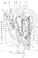
本発明の一実施形態に係る鞍乗り型車両として、図1にスクータ型の自動二輪車1の、前輪側を図示省略し、ボディカバーを一部切り欠いた要部左側面図を示す。
本実施形態の自動二輪車1は、内燃機関2と後輪への動力伝達装置3とが一体化されて、車体フレーム4に対して上下揺動自在に取り付けられたスイング式パワーユニット(以下、単に「パワーユニット」という)5を、乗員用シート10の下方に備えており、内燃機関2は、単気筒の4ストロークサイクル内燃機関である。パワーユニット5は、パワーユニットケース50のクランク軸20を自動二輪車1の車幅方向に配向させて、自動二輪車1に搭載される。
また、パワーユニット5には内燃機関2の吸気用のエアクリーナ6が支持されている。
As a saddle-ride type vehicle according to an embodiment of the present invention, FIG. 1 shows a left side view of a main part of a
In the
The
図1に示すように、本実施形態の自動二輪車1では、図示省略されているが、車体フレーム4の前端部に位置するヘッドパイプに、前輪を軸支する左右一対のフロントフォークがステアリングステムを介して操舵可能に枢支される。また、ステアリングステムの上部には、操舵用のハンドルが取り付けられる。
As shown in FIG. 1, in the
車体フレーム4は、ヘッドパイプから斜め下がり後方へメインフレームが接続し、図1に示されるように、その下部において左右一対のメインフレーム40A、40Aに分岐してほぼ水平後方に延出して、ヘッドパイプと乗員用シート10との間を低部として跨ぎ易さを向上させた鞍部41を形成する。
鞍部41上には、ステップフロア11が図示しないフロントカバーの下部後方と接続して設けられている。
The
On the
メインフレーム40A、40Aは、ステップフロア11の後方で屈曲部42をなして、左右一対の後部メインフレーム40B、40Bとして後方へ斜め上がりに延出した後、勾配を減じるように折れ曲がって後方に延出する。
後部メインフレーム40B、40B上には、前方から収納ボックス12、燃料タンク13等が支持され、その上部を覆うように乗員用シート10が支持されている。
左右対をなすメインフレーム40A、40A、後部メインフレーム40B、40Bはそれぞれ、車幅方向のフレームによって左右連結される。
The
On the rear
The
なお、図1中の符号14は後部リヤフェンダ、15はメインスタンド、16はサイドスタンド、である。メインスタンド15、サイドスタンド16は、走行中等不使用状態を実線で、使用状態を二点鎖線で示されている。
車体フレーム4は、主に合成樹脂からなるボディカバー17により覆われている。
In FIG. 1,
The
後輪7の後方を覆う後部リヤフェンダ14は、その上端において、後輪7上方を覆って車両前方に延出する上部リヤフェンダ70部材と接続している。
上部リヤフェンダ70部材は、勾配を減じるように折れ曲がって後端まで延出する左右の後部メインフレーム40B、40Bの下方に沿って、それらの間の上下を塞ぐ底板状に取り付けられており、後輪7から巻き上げられる水、塵埃等から、後部メインフレーム40B、40B間およびその上部に設けられる機器や、収納ボックス12、燃料タンク13等の装置を保護する(図2参照)。
The rear
The upper
パワーユニット5は、その前部の内燃機関2と後部左側の動力伝達装置3とを一体化し
てなり、そのパワーユニットケース50の前方下部にハンガー部51を備えている。
パワーユニット5はハンガー部51において、懸架リンク18を介して、メインフレーム40A、40Aから後部メインフレーム40B、40Bへの屈曲部42に取り付けられたピボットプレート43に、上下揺動可能に支持され、且つパワーユニット5の後部左側がリヤクッション19を介して後部メインフレーム40B、40Bに近接離反可能に支持される。
また、パワーユニットケース50の後部側に設けられた動力伝達装置3の後端部には、自動二輪車1の駆動輪である後輪7が、右側に隣接して軸支される。
The
The
A
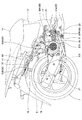
パワーユニットケース50の前方側には、水平に近く前傾して、シリンダブロック、シリンダヘッド、シリンダヘッドカバーが順次積み重ねられるように締結された、内燃機関2のシリンダ部21が備えられている。
On the front side of the
後輪7の左側方で、パワーユニット5の動力伝達装置3の上部、すなわちパワーユニットケース50の上部には、エアクリーナ6のエアクリーナケース60がその後端60aを、車体フレーム4とパワーユニット5との間に取り付けられたリヤクッション19より後方に配置させて、支持されている。
On the left side of the
内燃機関2のシリンダ部21のシリンダヘッド21a上部から延出した吸気管22は、後方に湾曲して気化器23とコネクティングチューブ24を介して、エアクリーナケース60の前部に接続されている(図2参照)。
また、シリンダ部21のシリンダヘッド21aの排気ポート25(図3参照)からは、下方に向けて排気管26が延出し、排気管26は右側へ迂回して車体右側に配設されたサイレンサ27に接続している。
The
Further, an
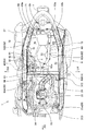
図2に示されるように、本実施形態において排気浄化装置8は、排気系に二次エアを供給して排気ガス中に含まれるHCやCO等の未燃焼成分を燃焼させるため、内燃機関2の排気通路をなす排気ポート25(図3参照)内に下流端が接続された二次エア供給管80と、二次エア供給管80の上流端と接続し二次エア供給管80への二次エアの供給を制御する二次エア制御バルブ90と、二次エア制御バルブ90に下流端が接続され二次エア制御バルブ90へ二次エアを導入する外気導入通路82とを備えている。
また、外気導入通路82の上流端は、外気導入開口82aとして開口しており、外気導入通路82の中途部に、二次エア用のエア濾過器83が介装されている。
外気導入通路82は、エア濾過器83より下流の下流側外気導入通路82Bと、エア濾過器83より上流の上流側外気導入通路82Aからなり、上流側外気導入通路82Aに共鳴通路84が設けられている。
As shown in FIG. 2, in the present embodiment, the
The upstream end of the outside
The outside
排気浄化装置8は、自動二輪車1の乗員用シート10下方で、後輪7上方を覆う上部リヤフェンダ部材70の上面に分散して配置されている。
二次エア制御バルブ90は、その入口開口部91の軸線Xを車両前後方向の後向きに配向して、入口開口部91を車両後方に向けて、上部リヤフェンダ部材70の前部の上面の右側に締結されて取り付けられている。
The exhaust
The secondary
入口開口部91に接続した下流側外気導入通路82Bは、右側の後部メインフレーム40Bの略内側に沿って後方に延設されるともに、上部リヤフェンダ部材70の後部で車両中心方向(左方向)に向けて滑らかに折れ曲がって、車両右方向に配向したエア濾過器83の出口部83bに接続する。
そのため、二次エア制御バルブ90の入口開口部91の負圧を、エア濾過器83まで有効に作用させることができる。
The downstream side outside
Therefore, the negative pressure at the inlet opening 91 of the secondary
エア濾過器83の入口部83aは車両左方向に配向し、上流側外気導入通路82Aが接続する。上流側外気導入通路82Aは滑らかに車両前方へ向けて折れ曲がって、左側の後部メインフレーム40B寄りに、左右の後部メインフレーム40B、40Bの間を前方に延設された後、外気導入開口82aとして開口する。
The
上流側外気導入通路82Aの折れ曲がり部82bよりやや上流側(前方)においては、車両左右方向に配向し、右端が閉じた管状の共鳴通路84の左端が分岐接続している。そのため、共鳴通路84によって、外気導入通路82内の脈動が低減し、吸気の流れが整流され、吸気効率を高めることができるとともに、脈動による外気導入開口82aの開口縁から出る騒音を低減することができる。
On the slightly upstream side (front) of the
また、エア濾過器83は、上部リヤフェンダ部材70後部に形成された保持用凹部71に保持された上を図示しないカバー部材が覆うように締結されて取り付けられ、外気導入通路82や共鳴通路84もまた上部リヤフェンダ部材70に形成された保持用溝部72に配置された上で、リブ73で止められている。二次エア制御バルブ90は、上部リヤフェンダ部材70の比較的低い位置にある前部において締結取り付けされている。
The
したがって、外気導入通路82は上部リヤフェンダ部材70上に滑らかにU字状に分散配置され、外気導入通路82の内部抵抗を小さくでき、二次エア供給性能を高められる。
また、排気浄化装置8の各構成機器が、左右の後部メインフレーム40B、40Bの間に囲まれて、上部リヤフェンダ部材70上に、取り付け上下高さを抑えて平たく分散配置され、それらを外気導入通路82が接続しているので、左右の後部メインフレーム40B、40Bの上に取り付けられる収納ボックス12、燃料タンク13等の取り付け高さを増大させない。
そのため、それらを覆って取り付けられる乗員用シート10の高さも低く保つことができ、後輪7の上下揺動高確保による乗り心地向上を図ることが可能となる。
また、排気浄化装置8の各構成機器が、左右の後部メインフレーム40B、40Bによって保護される。
Therefore, the outside
Further, each component of the exhaust
Therefore, the height of the
Moreover, each component apparatus of the exhaust
また、二次エア制御バルブ90とエア濾過器83は、上部リヤフェンダ部材70に取り付けられるので、排気浄化装置8を自動二輪車1に組み付けるに際して、予め小組みをしておけるので、組立て性も向上する。
Further, since the secondary
二次エア制御バルブ90には、前方に配向して出口開口部92が設けられ、制御された二次エアを内燃機関2の排気系に供給する。
出口開口部92には、二次エア供給管80の上流端が接続し、下流端は、排気通路となるシリンダヘッド21aの吸気ポート25内に開口するように接続している。
二次エア供給管80は、二次エア制御バルブ90に接続する側の上流側二次エア供給管80Aと、排気ポート25と接続する側の下流側二次エア供給管80Bからなり、接続部81で互いに接続連通される。
The secondary
The upstream end of the secondary
The secondary
本実施形態において下流側二次エア供給管80Bは、排気ポート25に設けられた図示しない接続孔を介して排気ポート25内に接続連通するように固定される。
なお、下流側二次エア供給管80Bが接続する本発明における「排気通路」としては、それに限らず、排気ポート25に接続した排気管26を排気通路として、下流側二次エア供給管80Bが排気管26に接続連通するように固定されもよい。
In the present embodiment, the downstream secondary
The “exhaust passage” in the present invention to which the downstream side secondary
下流側二次エア供給管80Bは、シリンダヘッド21aないしその至近距離の部材に接続し、その近傍に配管されるものであるので、その高温に耐えられる適宜な金属管を用いる。
一方、二次エア制御バルブ90は、車体フレーム4に固定された上部リヤフェンダ70部材上に固定され、シリンダヘッド21aは、パワーユニット5の一部として車体フレーム4に対して揺動するため、その揺動を吸収しつつ二次エア制御バルブ90と下流側二次エア供給管80Bを連結するために、上流側二次エア供給管80Aはゴム材等の適切な可撓性材料による管を用いる。
Since the downstream secondary
On the other hand, the secondary
また、二次エア制御バルブ90には、出口開口部92と並んで前方に配向して負圧導入部93が設けられ、負圧導入管94の一端が接続する。
負圧導入管94の他端は、気化器23の吸気下流側となる吸気管22と接続して、その内部と連通している。
Further, the secondary
The other end of the negative
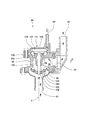
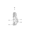
図4、図5に示されるように、二次エア制御バルブ90は、本体ケース95を備え、本体ケース95に、二次エアの入口開口部91と出口開口部92が形成されている。入口開口部91と出口開口部92は、本体ケース95内の二次エア室96に開口されている。また、入口開口部91には、外気導入通路82が接続されるとともに、出口開口部92には、二次エア供給管80が接続される。
As shown in FIGS. 4 and 5, the secondary
本体ケース95の二次エア室96には、出口開口部92近くにリード弁97が設けられている。リード弁97は、排気系内に発生する排気脈動圧に応じて開閉されるもので、出口開口部92に二次エア供給管80を介して排気ポート25内の負圧が作用すると、リード弁97が開かれ、入口開口部91と出口開口部92とが連通される。
A
また、本体ケース95には、内燃機関2の運転状況に応じた適切な二次エアを得るためのカット弁100と、カット弁100を駆動するためのアクチュエータ101が組み込まれている。
カット弁100は、入口開口部91とリード弁97の間で二次エア室97内を仕切る仕切り壁98に設けられた開口部分102に接離する弁体103と、弁体103を支持する弁軸104を備えている。
Further, the
The
アクチュエータ101は、本体ケース95に被せられたカバー105を備えており、このカバー105の内側にはダイアフラム106が収容されている。ダイアフラム106は、カバー105の内部を負圧室107と、二次エア室96と連通孔96aにより連通した二次エア圧室108とに区画している。負圧室107は、負圧導入管94を介して吸気管22に連なっており、負圧室107には、内燃機関2の運転中、吸気管22内の吸気負圧が導入されるようになっている。
The
カット弁100の弁軸104は、本体ケース95を摺動可能に貫通してダイアフラム106に連結されている。ダイアフラム106は、スプリング109によって二次エア圧室108側に押圧されており、そのため、弁体103が仕切り壁98の開口部分102から離脱され、カット弁100が常時開状態に維持されている。
The
上記のように、カット弁100が開いた状態で、内燃機関2の運転中、排気通路としての排気ポート25には排気脈動が生じるので、排気ポート25内の負圧が二次エア供給管80を介して二次エア制御バルブ90のリード弁97に伝わると、リード弁97が開かれ、外気導入通路82の外気導入開口82aから外気が二次エアとして吸入される。
As described above, exhaust pulsation occurs in the
吸入された二次エアは、上流側外気導入通路82Aを通じてエア濾過器83に導かれ、塵埃等が濾過される。エア濾過器83で濾過された清浄な二次エアは、下流側外気導入通路82Bを通り、二次エア制御バルブ90のリード弁97を通過し、二次エア供給管80を介して排気ポート25内に噴射され、排気ポート25を流れる排気ガスと混合される。そのため、排気ガス中の未燃焼成分が排気ポート25や排気管26のような排気系内で燃焼され、排気ガスの浄化が行われる。
The sucked secondary air is guided to the
一方、気化器23の図示しないスロットル弁を急激に閉じた時のような減速運転時には、気化器23のベンチュリー通路が絞られて吸気の流速が早くなり、燃料の吸い出し量が多くなる。その結果、混合気が一時的に過濃な状態となって、内燃機関2の図示しない燃焼室内で失火が生じることがあり、排気ポート25内に多量の未燃混合気が排出されてしまう。この時、排気ポート25内に二次エアが噴射されると、未燃混合気が二次空気との混合により適性な空燃比となって爆発的に燃焼する、いわゆるアフターバーンが発生する恐れがある。
On the other hand, during a deceleration operation such as when the throttle valve (not shown) of the
しかし、本実施形態の二次エア制御バルブ90は、その負圧室107と吸気管22とが負圧導入管94を介して連通されているので、減速運転時に吸気管22内の負圧が高くなると、ダイアフラム106がスプリング109の付勢力に抗して負圧室107に向けて変形する。すると、カット弁100の弁体103が、二次エア圧室108内の仕切り壁98の開口部分102に押圧され、開口部分102を閉塞する。その結果、減速運転時には、排気ポート25への二次エアの供給が停止され、アフターバーンの発生が防止される。
However, in the secondary
以下、本実施形態の鞍乗り型車両の排気浄化装置の特徴について述べる。
すなわち、本実施形態の鞍乗り型車両の排気浄化装置は、内燃機関2の排気通路としての排気ポート25に下流端が接続された二次エア供給管80と、二次エア供給管80の上流端と接続し二次エア供給管80への二次エアの供給を制御する二次エア制御バルブ90と、二次エア制御バルブ90への外気導入通路82とを備えた自動二輪車1の排気浄化装置8において、排気浄化装置8は、自動二輪車1における乗員用シート10下方で、後輪7上方を覆う上部リヤフェンダ部材70の上面に分散して配置され、外気導入通路82の中途部に、二次エア用のエア濾過器83と共鳴通路84とが設けられ、外気導入通路82および共鳴通路84はともに管状部材からなり、外気導入通路82は平面視で左右の後部メインフレーム40B、40B間にU字状に配置され、共鳴通路84はU字状の前記外気導入通路82の一辺に沿って配置されている。
Hereinafter, the features of the exhaust gas purification apparatus for saddle riding type vehicles of this embodiment will be described.
That is, the exhaust purification device for a saddle-ride type vehicle according to the present embodiment includes a secondary
したがって、共鳴通路84により、二次エアの外気導入通路82内の脈動を低減させ、流れを整流した構造としたので、吸気効率が高まり、脈動による外気導入開口82aの開口縁から出る騒音が低減するとともに、二次エア制御バルブ90とエア濾過器83およびその上流側の外気導入通路80(82A)の外気導入開口82aの開口縁までの、配置自由度が増して、自動二輪車1の隙間に、排気浄化装置8の各部分を分散配置することが容易となる。
その結果、二次エアによる排気浄化装置8の性能を維持しつつ、排気浄化装置8の配置に伴う自動二輪車1の大型化を防止できる排気浄化装置8となる。
また、上部リヤフェンダ部材70の上面に排気浄化装置8を分散して配置させることで、上下の所要取り付け高さを狭くして、周囲からの異物の侵入も低減でき、更にシート高さも抑えることができる。
またそのことにより、後輪7の上下揺動高確保による乗り心地向上を図ることが可能となる。
そして、外気導入通路82および共鳴通路84の平面的な配置によって、後輪7の上下揺動量確保、取付け上下高さの抑制がなされ、車両の大型化が防止される。
Therefore, the
As a result, the exhaust
Further, by disposing and arranging the
In addition, this makes it possible to improve the riding comfort by ensuring the vertical swing height of the
The planar arrangement of the outside
また、共鳴通路84は、エア濾過器83より上流側の外気導入通路82(82A)に設けられ、
エア濾過器83は上部リヤフェンダ部材70に形成された保持用凹部71に保持されて取り付けられ、外気導入通路82と共鳴通路84は上部リヤフェンダ部材70に形成された保持用溝部72に配置され、二次エア制御バルブ90は、上部リヤフェンダ部材70に取り付けられている。
そのため、さらに外気導入通路82の外気導入開口82aの開口縁から出る騒音を低減することができ、上部リヤフェンダ部材70上に、二次エア制御バルブ90とエア濾過器83と共鳴通路84を予め小組みができて、排気浄化装置8の組立て性が向上するほか、上部リヤフェンダ70に保持用凹部71と保持用溝部72が形成され、それらにエア濾過器83と外気導入通路82および共鳴通路84とが保持されて配置されることで、排気浄化装置8の、上下の所要取り付け高さをさらに狭くすることができる。
The
The
Therefore, noise from the opening edge of the outside air introduction opening 82a of the outside
また、二次エア制御バルブ90の入口開口部91の軸線Xは、車両前後方向の後向きに配向され、エア濾過器83は、二次エア制御バルブ90の車両後方側から外気導入通路82で接続されて配置されているので、二次エア制御バルブ90の入口開口部91の負圧をエア濾過器83まで有効に作用させることができ、二次エア供給性能が高められる。
Further, the axis X of the inlet opening 91 of the secondary
また、二次エア制御バルブ90は、上部リヤフェンダ部材70の前部の右側に設けられ、エア濾過器83は、上部リヤフェンダ70の後部に設けられるとともに、エア濾過器83より上流側の外気導入通路82(82A)は、上部リヤフェンダ部材70の前部の左側に延在させて設けられているので、外気導入通路82が上部リヤフェンダ部材70上にU字状に分散配置され、乗員シート10の高さを抑えながら,外気導入通路82の内部抵抗を小さくして、二次エア供給性能がより高められる。
The secondary
以上、本発明の一実施形態につき説明したが、本発明の態様が上記実施形態に限定されず、本発明の要旨の範囲で、多様な態様で実施されるものを含むことは勿論である。 Although one embodiment of the present invention has been described above, the aspect of the present invention is not limited to the above-described embodiment, and it is needless to say that the present invention includes those implemented in various aspects within the scope of the gist of the present invention.
1…自動二輪車、2…内燃機関、3…動力伝達装置、4…車体フレーム、5…パワーユニット(スイング式パワーユニット)、6…エアクリーナ、7…後輪、8…排気浄化装置、10…乗員用シート、12…収納ボックス、13…燃料タンク、17…ボディカバー、19…リヤクッション、20…クランク軸、21…シリンダ部、21a…シリンダヘッド、22…吸気管、23…気化器、24…コネクティングチューブ、25…排気ポート(排気通路)、26…排気管、40B…後部メインフレーム、50…パワーユニットケース、60…エアクリーナケース、70…上部リヤフェンダ部材、71…保持用凹部、72…保持用溝部、80…二次エア供給管、80A…上流側二次エア供給管、80B…下流側二次エア供給管、82…外気導入通路、82a…外気導入開口、82A…上流側外気導入通路、82B…下流側外気導入通路、83…エア濾過器、84…共鳴通路、90…二次エア制御バルブ、91…入口開口部、92…出口開口部、93…負圧導入部、94…負圧導入管、97…リード弁、100…カット弁、101…アクチュエータ、106…ダイアフラム
DESCRIPTION OF
Claims (4)
前記排気浄化装置(8)は、前記鞍乗り型車両(1)における乗員用シート(10)下方で、後輪(7)上方を覆う上部リヤフェンダ部材(70)の上面に分散して配置され、
前記外気導入通路(82)の中途部に、二次エア用のエア濾過器(83)と共鳴通路(84)とが設けられ、
前記外気導入通路(82)および共鳴通路(84)はともに管状部材からなり、前記外気導入通路(82)は平面視で左右の後部メインフレーム(40B、40B)間にU字状に配置され、前記共鳴通路(84)はU字状の前記外気導入通路(82)の一辺に沿って配置されたことを特徴とする鞍乗り型車両の排気浄化装置。 The secondary air supply pipe (80) having one end connected to the exhaust passage (25) of the internal combustion engine (2) and the other end of the secondary air supply pipe (80) are connected to the secondary air supply pipe (80 Of the saddle-ride type vehicle (1) having a secondary air control valve (90) for controlling the supply of secondary air to the air) and an outside air introduction passage (82) to the secondary air control valve (90). In the exhaust gas purification device (8),
The exhaust emission control device (8) is distributed on the upper surface of the upper rear fender member (70) covering the rear wheel (7) above the passenger seat (10) in the saddle-ride type vehicle (1),
In the middle of the outside air introduction passage (82), an air filter (83) for secondary air and a resonance passage (84) are provided ,
Both the outside air introduction passage (82) and the resonance passage (84) are made of tubular members, and the outside air introduction passage (82) is disposed in a U shape between the left and right rear main frames (40B, 40B) in plan view, The exhaust gas purification apparatus for a saddle-ride type vehicle, wherein the resonance passage (84) is disposed along one side of the U-shaped outside air introduction passage (82) .
前記エア濾過器(83)は前記上部リヤフェンダ部材(70)に形成された保持用凹部(71)に保持されて取り付けられ、前記外気導入通路(82)と前記共鳴通路(84)は前記上部リヤフェンダ部材(70)に形成された保持用溝部(72)に配置され、前記二次エア制御バルブ(90)は、前記上部リヤフェンダ部材(70)に取り付けられたことを特徴とする請求項1記載の鞍乗り型車両の排気浄化装置。 The resonance passage (84) is provided in the outside air introduction passage (82) upstream of the air filter (83) ,
The air filter (83) is held and attached to a holding recess (71) formed in the upper rear fender member (70), and the outside air introduction passage (82) and the resonance passage (84) are connected to the upper rear fender. The second air control valve (90) is disposed in a holding groove (72) formed in the member (70), and the secondary air control valve (90) is attached to the upper rear fender member (70) . An exhaust purification system for saddle-ride type vehicles .
前記エア濾過器(83)は、前記二次エア制御バルブ(90)の車両後方側から前記外気導入通路(82)で接続されて配置されたことを特徴とする請求項2記載の鞍乗り型車両の排気浄化装置。 The axis (X) of the inlet opening (91) of the secondary air control valve (90) is oriented backward in the vehicle longitudinal direction,
The saddle riding type according to claim 2, wherein the air filter (83) is arranged to be connected to the secondary air control valve (90) from the rear side of the vehicle through the outside air introduction passage (82). Vehicle exhaust purification system.
Priority Applications (3)
| Application Number | Priority Date | Filing Date | Title |
|---|---|---|---|
| JP2011045205A JP5778947B2 (en) | 2011-03-02 | 2011-03-02 | Exhaust gas purification device for saddle-ride type vehicles |
| CN201210036335.XA CN102654072B (en) | 2011-03-02 | 2012-02-17 | Exhaust purifying apparatus of saddle-ride type vehicle |
| US13/407,433 US8695328B2 (en) | 2011-03-02 | 2012-02-28 | Exhaust purifying apparatus of saddle-ride type vehicle |
Applications Claiming Priority (1)
| Application Number | Priority Date | Filing Date | Title |
|---|---|---|---|
| JP2011045205A JP5778947B2 (en) | 2011-03-02 | 2011-03-02 | Exhaust gas purification device for saddle-ride type vehicles |
Publications (2)
| Publication Number | Publication Date |
|---|---|
| JP2012180804A JP2012180804A (en) | 2012-09-20 |
| JP5778947B2 true JP5778947B2 (en) | 2015-09-16 |
Family
ID=46729783
Family Applications (1)
| Application Number | Title | Priority Date | Filing Date |
|---|---|---|---|
| JP2011045205A Active JP5778947B2 (en) | 2011-03-02 | 2011-03-02 | Exhaust gas purification device for saddle-ride type vehicles |
Country Status (3)
| Country | Link |
|---|---|
| US (1) | US8695328B2 (en) |
| JP (1) | JP5778947B2 (en) |
| CN (1) | CN102654072B (en) |
Families Citing this family (3)
| Publication number | Priority date | Publication date | Assignee | Title |
|---|---|---|---|---|
| JP2014173518A (en) * | 2013-03-11 | 2014-09-22 | Honda Motor Co Ltd | Exhaust purification device of utility engine |
| JP6190323B2 (en) * | 2014-03-05 | 2017-08-30 | 本田技研工業株式会社 | Saddle riding vehicle |
| CN112814771B (en) * | 2020-11-16 | 2022-10-04 | 浙江春风动力股份有限公司 | Motorcycle and exhaust device thereof |
Family Cites Families (14)
| Publication number | Priority date | Publication date | Assignee | Title |
|---|---|---|---|---|
| JPS5893916A (en) * | 1981-11-30 | 1983-06-03 | Honda Motor Co Ltd | Secondary air introduction device for motorcycles |
| JPS58106118A (en) * | 1981-12-18 | 1983-06-24 | Honda Motor Co Ltd | Introducing device of secondary air in autobicycle |
| JP3231400B2 (en) * | 1992-05-22 | 2001-11-19 | 本田技研工業株式会社 | Secondary air supply device for motorcycle |
| JP4287959B2 (en) * | 1999-10-01 | 2009-07-01 | 本田技研工業株式会社 | Exhaust purification equipment |
| JP3933875B2 (en) * | 2001-02-09 | 2007-06-20 | 本田技研工業株式会社 | Exhaust gas purification device for scooter type vehicle |
| JP3673759B2 (en) * | 2002-01-11 | 2005-07-20 | ヤマハ発動機株式会社 | Motorcycle exhaust purification system |
| US6745568B1 (en) * | 2003-03-27 | 2004-06-08 | Richard K. Squires | Turbo system and method of installing |
| JP2006183502A (en) * | 2004-12-27 | 2006-07-13 | Yamaha Motor Co Ltd | Engine misfire detection device and method, and saddle riding type vehicle |
| JP2007040249A (en) * | 2005-08-04 | 2007-02-15 | Yamaha Motor Co Ltd | Engine and vehicle having exhaust gas purification function |
| JP2007040250A (en) * | 2005-08-04 | 2007-02-15 | Yamaha Motor Co Ltd | Saddle-type vehicle with exhaust gas purification function |
| JP4520404B2 (en) * | 2005-09-28 | 2010-08-04 | 本田技研工業株式会社 | Secondary air supply device for motorcycles |
| US8429896B2 (en) * | 2006-04-18 | 2013-04-30 | Kohler Co. | Engine exhaust systems with secondary air injection systems |
| JP5046674B2 (en) * | 2007-02-07 | 2012-10-10 | 本田技研工業株式会社 | Catalyst arrangement structure for motorcycles |
| JP2009215997A (en) * | 2008-03-11 | 2009-09-24 | Yamaha Motor Co Ltd | Saddle riding type vehicle |
-
2011
- 2011-03-02 JP JP2011045205A patent/JP5778947B2/en active Active
-
2012
- 2012-02-17 CN CN201210036335.XA patent/CN102654072B/en active Active
- 2012-02-28 US US13/407,433 patent/US8695328B2/en not_active Expired - Fee Related
Also Published As
| Publication number | Publication date |
|---|---|
| CN102654072B (en) | 2015-04-15 |
| JP2012180804A (en) | 2012-09-20 |
| CN102654072A (en) | 2012-09-05 |
| US20120222414A1 (en) | 2012-09-06 |
| US8695328B2 (en) | 2014-04-15 |
Similar Documents
| Publication | Publication Date | Title |
|---|---|---|
| TWI461314B (en) | vehicle | |
| JP5315109B2 (en) | Open structure of vehicle canister | |
| CN101844600B (en) | Motorcycle | |
| JP5977626B2 (en) | Canister layout structure for saddle-ride type vehicles | |
| JP5371669B2 (en) | Scooter type vehicle | |
| JP2010155506A (en) | Saddle-riding type vehicle | |
| JP5753046B2 (en) | Canister layout for saddle riding type vehicles | |
| JP2011011599A (en) | Motorcycle | |
| CN102016283B (en) | Air intake device for two-wheeled motor vehicle | |
| JP5778947B2 (en) | Exhaust gas purification device for saddle-ride type vehicles | |
| JP5002351B2 (en) | Scooter type vehicle | |
| JP2008230492A (en) | Motorcycle fuel supply system | |
| JP5719264B2 (en) | Canister layout for saddle riding type vehicles | |
| JP6019569B2 (en) | Scooter type motorcycle | |
| JP5420490B2 (en) | Flexible member wiring structure for vehicle | |
| JP5811091B2 (en) | Scooter type motorcycle | |
| JP6237245B2 (en) | Canister system installation structure | |
| JP2013067271A (en) | Canister arranging structure of saddle riding type vehicle | |
| JP3815048B2 (en) | Secondary air supply device for scooter type vehicle | |
| JP7305696B2 (en) | straddle-type vehicle | |
| JP4520404B2 (en) | Secondary air supply device for motorcycles | |
| JP2007062601A (en) | Vaporizer arrangement structure in small vehicles | |
| JP2022077585A (en) | Straddle-type vehicle | |
| JP2013043542A (en) | Motorcycle | |
| JP2008087697A (en) | Saddle-type rough terrain vehicle |
Legal Events
| Date | Code | Title | Description |
|---|---|---|---|
| A621 | Written request for application examination |
Free format text: JAPANESE INTERMEDIATE CODE: A621 Effective date: 20131127 |
|
| A977 | Report on retrieval |
Free format text: JAPANESE INTERMEDIATE CODE: A971007 Effective date: 20141205 |
|
| A131 | Notification of reasons for refusal |
Free format text: JAPANESE INTERMEDIATE CODE: A131 Effective date: 20141209 |
|
| A521 | Written amendment |
Free format text: JAPANESE INTERMEDIATE CODE: A523 Effective date: 20150130 |
|
| TRDD | Decision of grant or rejection written | ||
| A01 | Written decision to grant a patent or to grant a registration (utility model) |
Free format text: JAPANESE INTERMEDIATE CODE: A01 Effective date: 20150707 |
|
| A61 | First payment of annual fees (during grant procedure) |
Free format text: JAPANESE INTERMEDIATE CODE: A61 Effective date: 20150710 |
|
| R150 | Certificate of patent or registration of utility model |
Ref document number: 5778947 Country of ref document: JP Free format text: JAPANESE INTERMEDIATE CODE: R150 |
|
| R250 | Receipt of annual fees |
Free format text: JAPANESE INTERMEDIATE CODE: R250 |