JP5778894B2 - lift device - Google Patents
lift device Download PDFInfo
- Publication number
- JP5778894B2 JP5778894B2 JP2010093111A JP2010093111A JP5778894B2 JP 5778894 B2 JP5778894 B2 JP 5778894B2 JP 2010093111 A JP2010093111 A JP 2010093111A JP 2010093111 A JP2010093111 A JP 2010093111A JP 5778894 B2 JP5778894 B2 JP 5778894B2
- Authority
- JP
- Japan
- Prior art keywords
- cam
- driven member
- cam surface
- main body
- followers
- Prior art date
- Legal status (The legal status is an assumption and is not a legal conclusion. Google has not performed a legal analysis and makes no representation as to the accuracy of the status listed.)
- Active
Links
Images


Description
本発明は、物体を昇降させる昇降装置に関する。 The present invention relates to a lifting device that lifts and lowers an object .
従来、リンクを利用した昇降装置、ねじ駆動による昇降装置、機械式ジャッキによる昇降装置等様々な構成の昇降装置が知られている。 2. Description of the Related Art Conventionally, lift devices having various configurations such as a lift device using a link, a screw drive lift device, and a mechanical jack lift device are known.
このような昇降装置の中で、歯車を介してスイングアームシャフトに動力を伝達する機構を有する特開2006−21927の昇降装置がある。 Among such lifting devices, there is a lifting device disclosed in Japanese Patent Application Laid-Open No. 2006-21927 having a mechanism for transmitting power to a swing arm shaft through a gear.
特開2006−21927の昇降装置では、長期間に渡って安定した昇降を実現するために歯車の耐久性が求められる。そのため、歯車の耐久性を向上させるべく、例えば浸炭、焼入れ等の熱処理を行う必要となるという問題がある。このような熱処理で排出せざるを得ないCO2によって環境負荷が大きくなってしまう可能性もある。 In the lifting device disclosed in Japanese Patent Application Laid-Open No. 2006-21927, the durability of the gear is required in order to achieve stable lifting over a long period of time. Therefore, in order to improve the durability of the gear, there is a problem that it is necessary to perform heat treatment such as carburizing and quenching. There is also a possibility that the environmental load increases due to CO2 that must be discharged by such heat treatment.
上記点より本発明は、歯車を使用することなく、長期間に渡って安定した昇降を実現できる昇降装置を提供することを目的とする。 In view of the above, an object of the present invention is to provide an elevating device that can realize stable elevating over a long period of time without using a gear.
上記課題を解決するため請求項1の昇降装置は、筒体の上端面の一部がカム面となっており、前記筒体の軸線回りに回動自在となっているカム部材と、前記カム部材の筒体の内側に配置される本体とこの本体から放射状に延出し前記カム面と接触するフォロアとを有する従動部材とを備え、従動部材が最も低い位置にあるときは、従動部材の本体がカム部材である回動自在の筒体の内側に収容された状態となる。 In order to solve the above-described problem, the lifting device according to claim 1 is a cam member in which a part of the upper end surface of the cylinder is a cam surface, and is rotatable about the axis of the cylinder, and the cam A driven member having a main body disposed inside the cylinder of the member and a follower extending radially from the main body and contacting the cam surface, and when the driven member is at the lowest position, the main body of the driven member Is housed inside a rotatable cylinder that is a cam member.
この請求項1の昇降装置によれば、カム部材と従動部材とからなる構成で歯車を使用することなく、長期間に渡って安定した昇降を実現できる。 According to the lifting and lowering device of the first aspect, it is possible to realize stable lifting and lowering over a long period of time without using a gear with a configuration including a cam member and a driven member.
また、従動部材の本体がカム部材である回動自在の筒体の内側に配置されるようになっているので、従動部材が最も低い位置にあるときは、従動部材の本体がカム部材である回動自在の筒体の内側に収容された状態となる。したがって、従動部材が最も低い位置にある時における昇降装置の全高を小さくすることができる。 Further, since the main body of the driven member is arranged inside the rotatable cylinder that is the cam member , when the driven member is at the lowest position, the main body of the driven member is the cam member . It will be in the state accommodated inside the rotatable cylinder. Therefore, the overall height of the lifting device when the driven member is at the lowest position can be reduced.
さらに、従動部材の本体がカム部材である回動自在の筒体の内側に配置されるようになっているので、昇降装置を設置する際に占有するスペースも小さくすることができる。 Furthermore, since the main body of the driven member is arranged inside the rotatable cylinder that is the cam member , the space occupied when installing the lifting device can be reduced.
請求項2の昇降装置は、前記昇降装置は、前記従動部材を昇降方向に案内するガイド機構を備える。 According to a second aspect of the present invention, the lifting device includes a guide mechanism that guides the driven member in the lifting direction.
請求項2の昇降装置によれば、請求項1に記載の昇降装置と同様に作用する上、ガイド機構によって従動部材の昇降が安定する。 According to the lifting and lowering device of the second aspect, the lifting and lowering device according to the first aspect operates in the same manner and the driven member is stabilized by the guide mechanism.
請求項3の昇降装置は、請求項1又は2に記載の昇降装置において、カム部材の横断面である円の中心と前記従動部材の重心とが上面視で同一位置にある。
Lifting device as claimed in
請求項3の昇降装置によれば、請求項1又は2に記載の昇降装置と同様に作用する上、前記カム部材の横断面である円の中心はカム部材の回動中心であり、このカム部材の回動中心と前記従動部材の本体の重心とが上面視で同一位置にあることによって、安定した昇降が可能となる。 According to the lifting device of the third aspect, the same function as the lifting device according to the first or second aspect is achieved, and the center of the circle which is a cross section of the cam member is the rotation center of the cam member. by the center of gravity of the main body of the rotation center and the sub rotary members of the members are in the same position when viewed, enabling stable lifting.
請求項4の昇降装置は、請求項1乃至請求項3のいずれかに記載の昇降装置において、前記筒体の上端面は、始点と終点とを有するカム面が複数回繰り返された形状となっており、前記従動部材は、前記カム面の繰り返し回数と同数のフォロアを有し、一つのカム面に一つのフォロアが接触するようになっている。 The lifting device according to a fourth aspect is the lifting device according to any one of the first to third aspects, wherein the upper end surface of the cylindrical body has a shape in which a cam surface having a start point and an end point is repeated a plurality of times. The follower member has the same number of followers as the number of repetitions of the cam surface, and one follower comes into contact with one cam surface.
請求項4の昇降装置によれば、請求項1乃至請求項3のいずれかに記載の昇降装置と同様に作用する上、従動部材の複数のフォロアがそれぞれカム面と接触しているので、従動部材の荷重を複数のフォロアに分散させることができ安定した昇降が可能となる。 According to the lifting and lowering device of the fourth aspect of the present invention, since it operates in the same manner as the lifting and lowering device according to any one of the first to third aspects, the follower of the driven member is in contact with the cam surface. The load of the member can be distributed to a plurality of followers, and stable lifting can be achieved.
また、従動部材の荷重を複数のフォロアに分散させることができるとともに、一つのカム面に一つのフォロアが接触するようになっていることによって、カム面及びフォロアの磨耗を低減することができる。 Further, the load of the driven member can be distributed to the plurality of followers, and the wear of the cam surface and the follower can be reduced by the fact that one follower comes into contact with one cam surface.
請求項5の昇降装置は、請求項4に記載の昇降装置において、複数の前記カム面の始点は、上面視でカム部材の横断面である円の中心回りに、360度を前記カム面の繰り返し回数で割った角度ごとに位置するようになっており、複数の前記フォロアは、上面視で前記従動部材の重心回りに前記角度ごとに本体から延出するように設けられている。 The lifting device according to claim 5 is the lifting device according to claim 4, wherein the start points of the plurality of cam surfaces are 360 degrees around the center of a circle that is a cross section of the cam member in a top view. The plurality of followers are provided so as to extend from the main body for each angle around the center of gravity of the driven member when viewed from above.
請求項5の昇降装置によれば、請求項4に記載の昇降装置と同様に作用する上、上記のような構成となっていることによって、360度を前記カム面の繰り返し回数で割った角度分だけカム部材を回動させることによって昇降させることが可能となっている。 According to the lifting device of the fifth aspect, the angle obtained by dividing 360 degrees by the number of repetitions of the cam surface is the same as the lifting device according to the fourth aspect. It can be moved up and down by rotating the cam member by that amount.
請求項1乃至5のいずれかの発明によれば、カム部材と従動部材とからなる構成で歯車を使用することなく、長期間に渡って安定した昇降を実現できるとともに環境負荷が小さい製品を製造することができる。 According to the invention of any one of claims 1 to 5, a product composed of a cam member and a driven member can be manufactured for a long period of time without using a gear, and a product with a low environmental load can be manufactured. can do.
以下、本発明の一実施形態の昇降装置1について図面に基づいて説明する。 Hereinafter, an elevator apparatus 1 according to an embodiment of the present invention will be described with reference to the drawings.
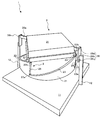
昇降装置1は、ベース11とこのベース11上に回動自在に設けられているカム部材2と、このカム部材2の回動によって昇降自在となっている従動部材3とを備える。
The lifting device 1 includes a
ベース11には、後述する従動部材3のガイド36が遊嵌した状態となっているガイドレール12,12が設けられている。ガイドレール12,12は従動部材3の昇降方向に立設している。ガイドレール12,12と後述するガイド36が、従動部材3を昇降方向に案内するガイド機構となっている。
The
カム部材2は、横断面が円形の筒体21であり、筒体21の軸線回りに回動自在となっている。カム部材2は、筒体21の上端面の一部がカム面22,23,24,25となっている。
The cam member 2 is a
筒体21の上端面は、同一形状のカム面22〜25が4回繰り返された形状となっている。それぞれのカム面22〜25は始点22a〜25aと終点22b〜25bとを有する。始点22a〜25aは、上面視でカム部材2の横断面である円の中心回りに、360度をカム面22〜25の繰り返し回数である4で割った角度である90度ごとに位置するようになっている。
The upper end surface of the
それぞれのカム面22〜25においては、始点22aと終点22bとの間、始点23aと終点23bとの間、始点24aと終点24bとの間及び始点25aと終点25bとの間が傾斜面となっている。カム面22の始点22aとカム面25の終点25bとの間、カム面23の始点23aとカム面22の終点22bとの間、カム面24の始点24aとカム面23の終点23bとの間及びカム面25の始点25aとカム面24の終点24bとの間に立ち上がり部26が形成されている。
In each of the
従動部材3は、カム部材2の筒体21の内側に配置される本体31と、この本体31から放射状に延出するフォロア32,33,34,35(フォロア34,35は斜視図のため見えず)と、本体31を昇降方向に案内するガイド36,36とを有する。
The driven
カム部材2の横断面である円の中心と従動部材3の重心とが上面視で同一位置にある。したがって、従動部材3の重心からの放射方向は、上面視でカム部材2の横断面である円の半径方向と一致するようになっている。
The center of gravity of the sub
フォロア32〜35は、カム面22〜25と同数となっており、それぞれ一つのカム面に一つのフォロアがそれぞれ接触するようになっている。斜視図では見えないが、フォロア34はカム面24に接触しており、フォロア35はカム面25に接触している。フォロア32〜35は、上面視で従動部材3の重心回りに90度ごとに本体31から延出するように設けられている。
The number of
フォロア32〜35は、ローラフォロアであって、そのローラフォロアの回転軸が上面視で従動部材3の重心からの放射方向と一致するようになっている。
The
ガイド36は、本体31から前述のガイドレール12に向って延出する腕部36aと、腕部36aの先端に設けられている板部36bと、ガイドレール12を挟む位置に板部36bに回動自在に設けられている2個のガイドローラ36c(図の向って右側のガイド36では、ガイドローラ36cは一方が見えるが他方は斜視図のため見えず、図の向って左側のガイド36では両方のガイドローラが見えず)とを備える。2個のガイドローラ36cがガイドレール12を挟むことによって、従動部材3のガイド36がガイドレール12と遊嵌した状態となっている。
The guide 36 is rotated around the
以下、昇降装置1の昇降動作について説明する。 Hereinafter, the lifting operation of the lifting device 1 will be described.
まずは、従動部材3を上昇させる動作について説明する。図1では、フォロア32〜35がそれぞれカム面22〜25の始点近傍に位置している。図1の状態からカム部材2が時計回り方向に回動すると従動部材3の自重によってフォロア32〜35がカム面22〜25の傾斜面に常に当接しつつ、フォロア32〜35がカム面22〜25と当接する位置が変わっていくことになる。フォロア32〜35はカム面22〜25の傾斜面に押し上げられ、従動部材3全体が上昇して図2の状態になる。図2の状態からさらにカム部材2が時計回り方向に回動するとフォロア32〜35がそれぞれカム面22〜25の終点22b〜25b近傍に到達し、さらに従動部材3全体が上昇した図3の状態となる。カム部材2の回動が止まることによって従動部材3の上昇が止まるようになっている。
First, an operation for raising the driven
次いで、従動部材3を下降させる動作について説明する。図3の状態からカム部材2が反時計周りに回動すると従動部材3の自重によってフォロア32〜35がカム面22〜25の傾斜面に常に当接しつつ、フォロア32〜35がカム面22〜25と当接する位置が変わっていくことになる。フォロア32〜35はカム面22〜25の傾斜面に追随して下がっていき、従動部材3全体が下降して図2の状態になる。図2の状態からさらにカム部材2が反時計回り方向に回動すると、フォロア32〜35がそれぞれカム面22〜25の始点22a〜25a近傍に到達し、さらに従動部材3全体が下降した図1の状態となる。
Next, an operation for lowering the driven
本発明は一組のカム部材と従動部材で昇降が可能となっている。複数組のカムと従動部材を有する機構ではカムの回転を同期させる必要となるが、本発明は同期させる必要がないので同期に必要な部品を減らすことができたり、電気的な制御を必要としない。 The present invention is capable of moving up and down with a pair of cam members and driven members. In a mechanism having a plurality of sets of cams and driven members, it is necessary to synchronize the rotation of the cams. However, since the present invention does not need to synchronize, it is possible to reduce the number of parts necessary for synchronization or to require electrical control. do not do.
また、本発明はカム面の傾斜に沿って従動部材を昇降させるので、例えばラックとピニオンを利用した昇降装置に比べて、出力の小さい動力源でも昇降可能となり、省エネを実現できる。さらに、本発明は、同出力の動力源であれば、例えばラックとピニオンを利用した昇降装置より重い物体を昇降させることができる。 Further, according to the present invention, since the driven member is moved up and down along the inclination of the cam surface, it is possible to move up and down even with a power source having a small output as compared with a lifting device using, for example, a rack and a pinion, thereby realizing energy saving. Furthermore, the present invention can lift and lower a heavier object than a lifting device using, for example, a rack and a pinion as long as the power source has the same output.
上記実施形態では、筒体21の上端面は、同一形状のカム面22,23,24,25が4回繰り返された形状となっている場合について説明したが、これに限定されることなく、同一形状のカム面が4回繰り返された回数は、例えば2回、3回、5回等の4回以外の複数回であってもよい。
In the said embodiment, although the upper end surface of the
上記実施形態では、隣り合うカム面、例えばカム面22とカム面25においては、カム面22の始点22aとカム面25の終点25bとの間に立ち上がり部26が形成されている場合について説明したが、これに限定されることなく、一方のカム面の始点と他方のカム面の終点との間が傾斜面であってもよい。
In the above embodiment, the case where the rising
また、カム面の始点近傍及び終点近傍にはフォロアの移動を制限するストッパー等が設けられていてもよい。 Further, a stopper or the like for restricting the movement of the follower may be provided in the vicinity of the start point and the end point of the cam surface.
上記実施形態では、フォロア32〜35は、ローラフォロアである場合について説明したが、これに限定されることなく、平板状あるいは曲面上の接触子であってもよい。
Although the case where the
上記実施形態では、ガイド36及びガイドレール12が二組の場合について説明したが、これに限定されることなく、ガイド36及びガイドレール12の組数は一組や三組,四組等の複数個であってもよい。
In the above-described embodiment, the case where the guide 36 and the
上記実施形態では、図中ではガイドレール12がカム部材2の外側にあるが、これに限定されることなく、カム部材2の内側に設けられてもよい。
In the above embodiment, the
上記実施形態では、ガイド機構がガイド36及びガイドレール12からなる場合について説明したが、これに限定されることなく、例えば従動部材の本体に穴が形成されており、その穴を貫通するガイド棒が設けられているなどといった他のガイド機構によって従動部材を案内してもよい。
In the above embodiment, the case where the guide mechanism is composed of the guide 36 and the
1 昇降装置
2 カム部材
3 従動部材
11 ベース
12 ガイドレール
21 筒体
22〜25 カム面
22a〜25a 始点
22b〜25b 終点
26 立ち上がり部
31 本体
32〜34 フォロア
36 ガイド
36a 腕部
36b 板部
36c ガイドローラ
DESCRIPTION OF SYMBOLS 1 Lifting device 2
Claims (5)
前記カム部材の筒体の内側に配置される本体とこの本体から放射状に延出し前記カム面と接触するフォロアとを有する従動部材とを備え、
従動部材が最も低い位置にあるときは、従動部材の本体がカム部材である回動自在の筒体の内側に収容された状態となることを特徴とする昇降装置。 A cylindrical member having a circular cross section, a part of the upper end surface of the cylindrical member is a cam surface, and a cam member that is rotatable about an axis of the cylindrical member;
A driven member having a main body disposed inside the cylindrical body of the cam member and a follower extending radially from the main body and contacting the cam surface;
An elevating apparatus characterized in that when the driven member is at the lowest position, the main body of the driven member is housed inside a rotatable cylinder that is a cam member.
前記従動部材は、前記カム面の繰り返し回数と同数のフォロアを有し、
一つのカム面に一つのフォロアが接触するようになっていることを特徴とする請求項1乃至3のいずれかに記載の昇降装置。 The upper end surface of the cylindrical body has a shape in which a cam surface having a start point and an end point is repeated a plurality of times,
The driven member has the same number of followers as the number of repetitions of the cam surface,
The lifting device according to any one of claims 1 to 3, wherein one follower is in contact with one cam surface.
複数の前記フォロアは、上面視で前記従動部材の重心回りに前記角度ごとに本体から延出するように設けられていることを特徴とする請求項4に記載の昇降装置。 The start points of the plurality of cam surfaces are positioned around the center of a circle that is a cross section of the cam member in a top view at every angle obtained by dividing 360 degrees by the number of repetitions of the cam surface,
The lifting device according to claim 4, wherein the plurality of followers are provided so as to extend from the main body at each angle around the center of gravity of the driven member in a top view.
Priority Applications (2)
| Application Number | Priority Date | Filing Date | Title |
|---|---|---|---|
| JP2010093111A JP5778894B2 (en) | 2010-04-14 | 2010-04-14 | lift device |
| CN2010105832241A CN102020221A (en) | 2010-04-14 | 2010-11-30 | Lifting device |
Applications Claiming Priority (1)
| Application Number | Priority Date | Filing Date | Title |
|---|---|---|---|
| JP2010093111A JP5778894B2 (en) | 2010-04-14 | 2010-04-14 | lift device |
Publications (2)
| Publication Number | Publication Date |
|---|---|
| JP2011219261A JP2011219261A (en) | 2011-11-04 |
| JP5778894B2 true JP5778894B2 (en) | 2015-09-16 |
Family
ID=43862053
Family Applications (1)
| Application Number | Title | Priority Date | Filing Date |
|---|---|---|---|
| JP2010093111A Active JP5778894B2 (en) | 2010-04-14 | 2010-04-14 | lift device |
Country Status (2)
| Country | Link |
|---|---|
| JP (1) | JP5778894B2 (en) |
| CN (1) | CN102020221A (en) |
Cited By (1)
| Publication number | Priority date | Publication date | Assignee | Title |
|---|---|---|---|---|
| CN112062045A (en) * | 2020-09-17 | 2020-12-11 | 杭州海康机器人技术有限公司 | Rotary lifting device |
Families Citing this family (6)
| Publication number | Priority date | Publication date | Assignee | Title |
|---|---|---|---|---|
| CN105966291B (en) * | 2016-06-21 | 2018-03-06 | 沈阳霹雳科技有限公司 | A kind of goods position regulating device of transport vehicle |
| CN109879203A (en) * | 2019-04-23 | 2019-06-14 | 北京旷视机器人技术有限公司 | Lifting mechanism and transfer robot with it |
| CN111941132A (en) * | 2020-08-19 | 2020-11-17 | 徐玉芝 | Stable mechanical lifting device for casting machining |
| CN112092049B (en) * | 2020-09-02 | 2022-01-25 | 安徽万朗磁塑股份有限公司 | Cam type double-cutting-piece refrigerator door seal cutting device |
| CN112296932B (en) * | 2020-10-30 | 2022-05-03 | 东风设备制造有限公司 | Part throw-off locating pin lifting device |
| CN114684968B (en) * | 2022-04-06 | 2023-06-16 | 何永雪 | Portable household water treatment environment-friendly device |
Family Cites Families (10)
| Publication number | Priority date | Publication date | Assignee | Title |
|---|---|---|---|---|
| US3884128A (en) * | 1972-07-06 | 1975-05-20 | Dura Corp | Combination centering bearing and stop for car lift pistons |
| JPS5546671Y2 (en) * | 1976-12-01 | 1980-11-01 | ||
| CN2160845Y (en) * | 1992-10-26 | 1994-04-06 | 魏德芳 | Energy saver for gas stove |
| JPH06226694A (en) * | 1993-02-02 | 1994-08-16 | Aiseru Kk | Sheet transfer method and device for its execution |
| CN1164750A (en) * | 1996-05-05 | 1997-11-12 | 张雄伟 | Power-off time-delay lamp switch |
| JP2003285994A (en) * | 2002-03-28 | 2003-10-07 | Hirata Corp | Elevating apparatus |
| CN1451600A (en) * | 2003-05-26 | 2003-10-29 | 刘文杰 | Body lifting method and lifting device thereby |
| JP2006021927A (en) * | 2004-07-09 | 2006-01-26 | Hiromasa Kitaguchi | Lifting device |
| JP5022855B2 (en) * | 2007-10-05 | 2012-09-12 | 古河機械金属株式会社 | Lift pin mechanism, heat treatment device, vacuum drying device |
| CN201128424Y (en) * | 2007-11-23 | 2008-10-08 | 宝山钢铁股份有限公司 | Passive lifting tool trolley |
-
2010
- 2010-04-14 JP JP2010093111A patent/JP5778894B2/en active Active
- 2010-11-30 CN CN2010105832241A patent/CN102020221A/en active Pending
Cited By (2)
| Publication number | Priority date | Publication date | Assignee | Title |
|---|---|---|---|---|
| CN112062045A (en) * | 2020-09-17 | 2020-12-11 | 杭州海康机器人技术有限公司 | Rotary lifting device |
| CN112062045B (en) * | 2020-09-17 | 2021-10-29 | 杭州海康机器人技术有限公司 | Rotary lifting device |
Also Published As
| Publication number | Publication date |
|---|---|
| CN102020221A (en) | 2011-04-20 |
| JP2011219261A (en) | 2011-11-04 |
Similar Documents
| Publication | Publication Date | Title |
|---|---|---|
| JP5778894B2 (en) | lift device | |
| JP6706745B2 (en) | Transfer device | |
| US20170001811A1 (en) | Transfer device | |
| JP6564986B2 (en) | Transported material discharge device | |
| JP2016175735A (en) | Transportation mechanism | |
| JP6139063B2 (en) | Pallet transport device | |
| JP2014084562A (en) | Tray traverse device for fork parking | |
| CN202777751U (en) | Transmission mechanism for pushing mahjong tiles to center of tile storage | |
| CN102728056B (en) | Compound driving device capable of pushing mahjong into middle of mahjong storage groove | |
| CN106400767A (en) | Ocean platform lifting device | |
| CN201082831Y (en) | Stack disc conveying controlling device | |
| CN202724658U (en) | Combined transmission device capable of pushing mahjong tiles to central position of tile storage groove | |
| CN103538911B (en) | A kind of manufacturing line carries out rotating the device controlled to west watt | |
| CN114404202B (en) | Posture adjustment positioning device for gastric lavage of ICU acute poisoning patient | |
| JP2007276916A (en) | Multi-synchronous type lifter | |
| CN211585182U (en) | Lifting device of mahjong machine | |
| JP2019034834A (en) | Unmanned carrier | |
| CN116219145B (en) | Annealing furnace for liquefied gas steel cylinder production | |
| CN208137556U (en) | Lifting device for tower-type space garage | |
| JP5697440B2 (en) | Lifting guide rail device | |
| CN205449271U (en) | Weight load and uninstallation mechanism | |
| JP6013697B1 (en) | lift device | |
| CN209097758U (en) | A kind of automatic telescopic loading platform | |
| CN106062944A (en) | Lifting device for substrate transfer apparatus and substrate transfer apparatus comprising same | |
| JP2000191299A (en) | Elevating device |
Legal Events
| Date | Code | Title | Description |
|---|---|---|---|
| A621 | Written request for application examination |
Free format text: JAPANESE INTERMEDIATE CODE: A621 Effective date: 20130221 |
|
| A977 | Report on retrieval |
Free format text: JAPANESE INTERMEDIATE CODE: A971007 Effective date: 20140213 |
|
| A131 | Notification of reasons for refusal |
Free format text: JAPANESE INTERMEDIATE CODE: A131 Effective date: 20140225 |
|
| A521 | Request for written amendment filed |
Free format text: JAPANESE INTERMEDIATE CODE: A523 Effective date: 20140404 |
|
| A131 | Notification of reasons for refusal |
Free format text: JAPANESE INTERMEDIATE CODE: A131 Effective date: 20140930 |
|
| A521 | Request for written amendment filed |
Free format text: JAPANESE INTERMEDIATE CODE: A523 Effective date: 20141110 |
|
| TRDD | Decision of grant or rejection written | ||
| A01 | Written decision to grant a patent or to grant a registration (utility model) |
Free format text: JAPANESE INTERMEDIATE CODE: A01 Effective date: 20150623 |
|
| A61 | First payment of annual fees (during grant procedure) |
Free format text: JAPANESE INTERMEDIATE CODE: A61 Effective date: 20150710 |
|
| R150 | Certificate of patent or registration of utility model |
Ref document number: 5778894 Country of ref document: JP Free format text: JAPANESE INTERMEDIATE CODE: R150 |
|
| R250 | Receipt of annual fees |
Free format text: JAPANESE INTERMEDIATE CODE: R250 |
|
| R250 | Receipt of annual fees |
Free format text: JAPANESE INTERMEDIATE CODE: R250 |
|
| R250 | Receipt of annual fees |
Free format text: JAPANESE INTERMEDIATE CODE: R250 |
|
| R250 | Receipt of annual fees |
Free format text: JAPANESE INTERMEDIATE CODE: R250 |
|
| R250 | Receipt of annual fees |
Free format text: JAPANESE INTERMEDIATE CODE: R250 |
|
| R250 | Receipt of annual fees |
Free format text: JAPANESE INTERMEDIATE CODE: R250 |