JP5777007B2 - Bringing member and external member mounting structure using the same - Google Patents
Bringing member and external member mounting structure using the same Download PDFInfo
- Publication number
- JP5777007B2 JP5777007B2 JP2011221870A JP2011221870A JP5777007B2 JP 5777007 B2 JP5777007 B2 JP 5777007B2 JP 2011221870 A JP2011221870 A JP 2011221870A JP 2011221870 A JP2011221870 A JP 2011221870A JP 5777007 B2 JP5777007 B2 JP 5777007B2
- Authority
- JP
- Japan
- Prior art keywords
- take
- out member
- mountain
- weir
- roof
- Prior art date
- Legal status (The legal status is an assumption and is not a legal conclusion. Google has not performed a legal analysis and makes no representation as to the accuracy of the status listed.)
- Active
Links
Images


Description
本発明は、新設、既設を問わず建築物の屋根に施工される多種の縦葺き(縦張り)外装構造に適用でき、太陽電池システムや緑化構造等を取り付けることができ、作製コストも低く抑えることができる持出部材、及びそれを用いた外設部材の取付構造に関する。 INDUSTRIAL APPLICABILITY The present invention can be applied to a variety of vertical (vertically stretched) exterior structures that are constructed on the roof of a building regardless of whether they are newly installed or installed, and can be attached with a solar cell system, a greening structure, and the like, and the manufacturing cost is kept low The present invention relates to a take-out member that can be used, and an external member mounting structure using the same.
近年、社会的情勢及び政治的情勢が相俟って太陽エネルギー変換モジュール(以下、太陽電池モジュールという)への期待はますます高まっており、既設の構造物や建築物の屋根面への太陽電池パネルの取り付け要請もまた高まっている。
他方、二酸化炭素を減少させるために、屋根面を緑化して温度低下や光合成を行わせる試みも盛んに行われている。
In recent years, combined with social and political conditions, expectations for solar energy conversion modules (hereinafter referred to as solar cell modules) are increasing, and solar cells on the roof of existing structures and buildings are increasing. There is also a growing demand for panel mounting.
On the other hand, in order to reduce carbon dioxide, attempts to reduce the temperature and perform photosynthesis by greening the roof surface are also actively conducted.
従来、縦葺き屋根上に太陽電池モジュールや緑化構造等の外設部材を取り付ける場合には、屋根の縦桟部分(屋根板もしくはカバー)に直接釘(ビス)等を打ち込んで固定したり、屋根材のハゼ部(縦桟)の外側を金具で挟み、ボルトで締着して取り付ける方法が知られている。特に太陽電池モジュールの場合には、国内だけでも数社に及ぶ各メーカー毎に太陽電池パネルのサイズが異なるため、専用の固定金具の上に鋼材を桁状に取り付けする方法が採られている。 Conventionally, when installing external components such as solar cell modules and greening structures on vertical roofs, nails (screws) are driven directly into the vertical beam (roof plate or cover) of the roof. A method is known in which the outer side of the cross section (vertical crosspiece) of the material is clamped with a metal fitting and fastened with a bolt. In particular, in the case of a solar cell module, the size of the solar cell panel is different for each manufacturer in several companies in Japan alone, and therefore, a method of attaching a steel material in a girder shape on a dedicated fixing bracket has been adopted.
しかし、前記屋根材のハゼ部(縦桟)の外側を金具で挟み込む方法では、ボルトの締着強度が十分でないと、ズレ動いたり落下することがあり、締め付けすぎると、ハゼ部や金具が変形又は破断することがあった。
なお、屋根面を構築する屋根材メーカーも、前記太陽電池モジュールのメーカーと同様に国内だけでも数社に及んでおり、それぞれの異なる仕様において、各種の屋根材に対して持出部材を取り付けるための構造が提案されている。
However, in the method of sandwiching the outside of the roof part (vertical beam) of the roofing material with a metal fitting, the bolt may move or fall if the fastening strength is not sufficient. Or it sometimes broke.
In addition, there are several roof material manufacturers that construct the roof surface in Japan as well as the solar cell module manufacturer, and in order to attach take-out members to various roof materials under different specifications. The structure is proposed.
そこで、本発明者らは、特許文献1にて、屋根面の山状部分に固定する下側金具と、固定部分から下方に位置する部分にて連結する上側金具とからなる持出部材を提案した。
Therefore, the present inventors have proposed a take-out member comprising, in
前記特許文献1に記載の持出部材は、屋根面へ固定するための固定具によって形成される穿孔への雨水の浸入を、上側金具が阻止し、確実に屋根上に取り付けることができるという利点があるものの、持出部材が二部材(上側部材、下側部材)にて構成されるため、各部材の作製等に費用がかかるという欠点があった。
The take-out member described in
そこで、本発明は、建築物の屋根に施工される多種の縦葺き(縦張り)外装構造に適用でき、太陽電池システムや緑化構造等を取り付けることができ、作製コストも低く抑えることができる持出部材、及びそれを用いた外設部材の取付構造を提案することを目的とする。 Therefore, the present invention can be applied to various types of vertical (vertically stretched) exterior structures that are constructed on the roof of a building, can be attached with a solar cell system, a greening structure, and the like, and can be manufactured at a low cost. It aims at proposing the attachment structure of an extraction member and an external member using the same.
本発明は、上記に鑑み提案されたものであって、山状部分と谷状部分とが連続する屋根面に設置する持出部材であって、山状部分を構成する左右の傾斜面にそれぞれ沿わせる脚部と、山状部分の頂部に外設部材又は外設部材を支持する支持材の取付部と、を有し、前記左右の脚部には、固定具が挿通する孔と、該孔の上方及び側方からの流水を防ぐ堰状部とをそれぞれ複数設けてなることを特徴とする持出部材に関するものである。 The present invention, which was proposed in view of the above, a the draw member to be installed on the roof of the mountain-shaped portion and a trough portion are continuous, respectively on the inclined surfaces of the right and left which constitutes the mountain-shaped portion A leg portion to be fitted, and an attachment member for supporting the external member or the external member on the top of the mountain-shaped portion, and the left and right leg portions have holes through which a fixture is inserted, and The present invention relates to a take-out member characterized in that a plurality of weir-like portions that prevent running water from above and from the side of the hole are provided.
また、本発明は、前記持出部材において、堰状部は、裏面側に空間を有する隆状部にて形成されていることを特徴とする持出部材をも提案する。 The present invention also proposes a take-out member characterized in that, in the take-out member, the weir-like portion is formed by a ridge having a space on the back surface side.
また、本発明は、前記持出部材において、取付部は、裏面側に連結用のボルトの頭部又はナットを収容する収納部であることを特徴とする持出部材をも提案する。 The present invention also proposes a take-out member, characterized in that, in the take-out member, the attachment portion is a storage portion that accommodates a head portion or a nut of a connecting bolt on the back surface side.
また、本発明は、前記持出部材において、脚部の裏面には、止水ゴムが介在されていることを特徴とする持出部材をも提案する。 The present invention also proposes a take-out member characterized in that a water-stopping rubber is interposed on the back surface of the leg portion in the take-out member.
さらに、本発明は、山状部分と谷状部分とが連続する屋根面に前記持出部材を設置し、さらにその収容部の上面に外設部材又は外設部材を支持する支持材を取り付けてなることを特徴とする外設部材の取付構造をも提案するものである。 Further, in the present invention, the take-out member is installed on a roof surface where a mountain-shaped portion and a valley-shaped portion are continuous, and an external member or a support material that supports the external member is attached to the upper surface of the accommodating portion. The present invention also proposes an external member mounting structure characterized by
本発明の持出部材は、屋根の山状部分に脚部を沿わせ、孔から固定具を打ち込んで強固に屋根面に固定することができ、孔の周囲に堰状部を形成しているので、上方や側方からの雨水は堰状部によって迂回されて排水されるため、固定具によって形成される穿孔への雨水の浸入を堰状部が防止することができる。 The take-out member of the present invention has a leg portion along the mountain-shaped portion of the roof, and can be firmly fixed to the roof surface by driving a fixing tool through the hole, and a weir-like portion is formed around the hole. Therefore, rainwater from above or from the side is detoured and drained by the dam-like portion, and thus the dam-like portion can prevent rainwater from entering the perforations formed by the fixture.
また、堰状部が、裏面側に空間を有する隆状部にて形成されている場合には、吹き上げ風力等にて雨水が裏面側の空間内へ浸入しても、雨水が裏面側空間を回るだけであって、孔への浸入を生ずることがなく、固定具によって形成される穿孔への雨水の浸入を隆状部が防止することができる。 In addition, when the dam-like portion is formed by a ridge having a space on the back side, even if rainwater infiltrates into the space on the back side by blowing wind force or the like, the rainwater does not enter the back side space. The ridges can be prevented from entering the perforations formed by the fasteners, without turning into the holes and only causing rotation.
また、取付部が、裏面側に連結用のボルトの頭部又はナットを収容する収納部である場合には、例えばボルトの上端に押さえ材等を配してナットで締め付け固定して外設部材や支持材を取り付けることができる。ナットの場合には、押さえ材等を配してボルトで締め付け固定すればよい。 In addition, when the mounting portion is a housing portion that accommodates the head of the connecting bolt or the nut on the back side, for example, a pressing member is disposed on the upper end of the bolt and is fastened and fixed with the nut. And support material can be attached. In the case of a nut, a presser material or the like may be provided and fastened with a bolt.
また、脚部の裏面に止水ゴムを介在させている場合、固定具によって形成される穿孔への雨水の浸入を止水ゴムが直接的(物理的)に防止する役割を果たすため、雨仕舞いがより確実なものになる。 In addition, when a water stop rubber is interposed on the back of the leg, the water stop rubber directly (physically) prevents the rain water from entering the perforations formed by the fixture. Will be more certain.
さらに、本発明の外設部材の取付構造は、前述のように屋根に強固に取り付けた持出部材に直接的に外設部材を取り付けるか、或いは支持材を取り付け、該支持材に外設部材を取り付けたものであるから、極めて容易に外設部材の取付を実施できるものである。 Furthermore, the mounting structure of the external member of the present invention is such that the external member is directly attached to the takeout member that is firmly attached to the roof as described above, or a support material is attached, and the external member is attached to the support material. Therefore, the external member can be attached very easily.
本発明の持出部材は、山状部分と谷状部分とが連続する屋根面に設置する部材であり、山状部分を構成する傾斜面に沿わせる脚部と、山状部分の頂部に外設部材又は外設部材を支持する支持材の取付部と、を有し、前記脚部には、固定具が挿通する孔と、該孔の上方及び側方からの流水を防ぐ堰状部とを設けてなる構成である。
なお、持出部材という名称に関し、持出金具(もちだしかなぐ)という名称が一般的であるが、金属製に限定されるものではなく、例えば硬質の樹脂成型品でもよいため、持出部材とした。
以下に、この持出部材の(A)脚部、(B)取付部について順に説明する。
The take-out member of the present invention is a member installed on a roof surface where a mountain-shaped portion and a valley-shaped portion are continuous, and is attached to a leg portion along an inclined surface constituting the mountain-shaped portion and a top portion of the mountain-shaped portion. An attachment portion for supporting material that supports the installation member or the external member, and the leg portion includes a hole through which the fixture is inserted, and a weir-like portion that prevents flowing water from above and from the side of the hole. Is provided.
As for the name of the take-out member, the name of take-out metal fittings is generally used, but is not limited to metal, and may be, for example, a hard resin molded product. It was.
Below, the (A) leg part and (B) attachment part of this taking-out member are demonstrated in order.
(A)脚部
本発明の持出部材の脚部は、持出部材を屋根に取り付けるための部位であって、概略的には屋根面の山状部分を構成する二つの傾斜面に沿わせる二つの傾斜面状に形成される。なお、後述する図示実施例のように山状部分の頂部が台状である場合などは、厳密には傾斜面と頂部の一部に沿わせる略く字状に形成されることもある。
この脚部には、前述のように固定具が挿通する孔と、該孔の上方及び側方からの流水を防ぐ堰状部とを設けてなる。
(A) Leg part The leg part of the taking-out member of the present invention is a part for attaching the taking-out member to the roof, and is generally along two inclined surfaces constituting the mountain-shaped portion of the roof surface. Two inclined surfaces are formed. Strictly speaking, when the top portion of the mountain-shaped portion is trapezoidal as in the illustrated embodiment described later, it may be formed in a substantially square shape along the inclined surface and part of the top portion.
As described above, the leg portion is provided with a hole through which the fixture is inserted and a weir-like portion that prevents flowing water from above and from the side of the hole.
前記孔は、脚部に固定具を打ち込んで固定するものであるから、使用する固定具に応じて所定の大きさに形成すればよい。
前記堰状部は、前記孔の上方及び側方からの流水を防ぐものであり、この堰状部としては、孔の周囲に他の部分より高い囲い部を設けたものでもよく、或いは孔を含む所定範囲が他の部分より高い台状部を設けたものでもよい。これらの囲い部や台状部は、他の部分より厚肉に形成したものでもよいが、後述する第1、第3実施例のように、裏面側に空間を有する隆状部にて形成されるものであってもよいし、或いは後述する第2実施例のように孔を含む所定範囲を台状に隆起させて形成した台状部の段差にて形成されるものでもよい。特に裏面側に空間を有する隆状部にて形成される堰状部では、表面側では孔付近への雨水の流下を防ぎ、裏面側にあっては、外装材と本持出部材間に浸入した雨水を孔に近づけることなく排出させることができる。そのため、下方が塞がっていると裏面側に浸入した雨水の排出経路がなくなってしまうことにつながる。よって、この隆状部にて形成される堰状部は、下方が開放状に形成されている
Since the hole is for fixing a fixed member by driving it into the leg, it may be formed in a predetermined size according to the fixed member to be used.
The dam-like portion prevents water flowing from above and from the side of the hole, and the dam-like portion may have a surrounding wall with a higher enclosure than the other part, It is also possible to provide a trapezoidal portion whose predetermined range is higher than other portions. These enclosure parts and base parts may be formed thicker than other parts, but they are formed by ridges having a space on the back side as in the first and third embodiments described later. Alternatively, it may be formed by a step of a trapezoidal portion formed by raising a predetermined range including a hole in a trapezoidal manner as in the second embodiment described later. In particular, in the weir-shaped part formed with a ridge part having a space on the back side, rainwater flows to the vicinity of the hole on the front side, and on the back side, it enters between the exterior material and the main carry-out member. The drained rainwater can be discharged without getting close to the hole. Therefore, if the lower part is blocked, the drainage path of rainwater entering the back side will be lost. Therefore, the lower part of the weir-like part formed by this ridge-like part is formed open.
また、固定具によって形成される穿孔への雨水の浸入を防止するため、予め脚部の裏面に止水ゴムを介在させた状態で固定具を固定することが望ましく、この止水ゴムによって、より確実に雨水の浸入が防止されるものとなり、雨仕舞いがより確実なものになる。 In addition, in order to prevent rainwater from entering the perforations formed by the fixture, it is desirable to fix the fixture in a state in which a waterproof rubber is interposed on the back surface of the leg portion in advance. It will surely prevent the intrusion of rainwater, and the rain will be more reliable.
(B)取付部
本発明の持出部材の取付部は、山状部分の頂部に外設部材又は外設部材を支持する支持材を取り付ける部位であって、後述する図示実施例では下方が開放する矩形状の枠体に形成したが、特に限定するものではない。なお、この取付部の開放部分である下端が、前記脚部の基端であり、屋根面に突状部が形成される場合には、該突状部にこの収容部を被せるように配設してもよい。
この取付部は、裏面側に連結用のボルトの頭部又はナットを収容する収納部であってもよく、この場合、その上面には通孔が形成される。
(B) Attachment part The attachment part of the take-out member of the present invention is a part where an external member or a support material that supports the external member is attached to the top of the mountain-shaped part, and the lower part is opened in the illustrated embodiment described later. However, it is not particularly limited. The lower end, which is the open portion of the mounting portion, is the base end of the leg portion, and when a protruding portion is formed on the roof surface, the protruding portion is disposed so as to cover the accommodating portion. May be.
The mounting portion may be a housing portion that accommodates a head portion or a nut of a connecting bolt on the back surface side, and in this case, a through hole is formed on the upper surface thereof.
このように本発明の持出部材は、その脚部も取付部も、極めて簡易な構成であるから、各メーカーの種々の屋根仕様に対し、例えば脚部を、山状部分を構成する傾斜面に沿わせる傾斜角度を変更すればよい。また、この持出部材は、外設部材を支持する強度を有することが望ましいため、アルミ押出成形品やメッキ鋼板、ステンレス鋼板等のプレス加工品などが望ましい。 As described above, the taking-out member of the present invention has an extremely simple structure for both the leg portion and the attachment portion. Therefore, for various roof specifications of each manufacturer, for example, the leg portion is an inclined surface constituting a mountain-shaped portion. It is sufficient to change the inclination angle along the line. Moreover, since it is desirable that this take-out member has a strength to support the external member, an aluminum extruded product, a pressed product such as a plated steel plate, a stainless steel plate, or the like is desirable.
なお、本発明の持出部材を設置する屋根面は、前述のように山状部分と谷状部分とが連続する構成を有するものであればよく、新築でも既設でもよいが、特に既設屋根への太陽エネルギー変換モジュールや緑化構造等の各種外設部材の取付けに好適であり、改修屋根の構築にも適用できる。 Note that the roof surface on which the take-out member of the present invention is installed has only to have a configuration in which the mountain-like portion and the valley-like portion are continuous as described above, and may be a new construction or an existing construction. It is suitable for mounting various external members such as solar energy conversion modules and greening structures, and can also be applied to the construction of modified roofs.
このような脚部と取付部とからなる本発明の持出部材には、取付部の頂部に外設部材を直接的に取り付けてもよいし、支持材を介して間接的に取り付けてもよい。
特に取付部が前述のように裏面側に連結用のボルトの頭部又はナットを収容する収納部である場合には、該連結用のボルト又はナットを用いて容易に取り付け固定することができる。例えばボルトの上端に押さえ材等を配してナットで締め付け固定して外設部材や支持材を取り付けることができる。
に支持金具を固定してもよい。
An external member may be directly attached to the top portion of the attachment portion, or indirectly attached via a support member, to the takeout member of the present invention composed of such leg portions and attachment portions. .
In particular, when the attachment portion is a storage portion that accommodates the head or nut of the connecting bolt on the back side as described above, it can be easily attached and fixed using the connecting bolt or nut. For example, a pressing member or the like can be arranged on the upper end of the bolt and fixed with a nut to attach an external member or a support material.
A support metal fitting may be fixed to.
また、外設部材を支持する支持材は、前記取付部の頂部に直接的に取り付けてもよいし、前記支持材を介して間接的に取り付けてもよい。
この支持材は、特にその形状や構成等を限定するものではないが、後述する図示実施例のように桁行き方向に連続する逆U字状の長尺材又は定尺材でもよいし、流れ方向に連続する長尺材又は定尺材でもよい。
Moreover, the support material which supports an external member may be directly attached to the top part of the attachment part, or may be attached indirectly via the support material.
The support material is not particularly limited in shape, configuration, or the like, but may be an inverted U-shaped long material or a standard material that is continuous in the direction of travel as shown in the illustrated embodiment described later. It may be a long or continuous material that is continuous in the direction.
前記支持材を介して取り付けられる、或いは直接的に取付部に取り付けられる外設部材としては、太陽電池システムを後述する図示実施例にて説明するが、それに限定するものではなく、屋根面に適用される外設部材であれば、例えば緑化構造でも、雪止め金具でもよいし、避雷針、アンテナなどでもよい。
支持材を介して外設部材を取り付ける場合、外設部材の配設位置は、前記支持材の任意の位置に取り付けることができるので、屋根面の任意の位置に取り付けることができる。
As an external member attached via the support material or directly attached to the attachment portion, the solar cell system will be described in the illustrated embodiment described later, but is not limited thereto, and is applied to the roof surface. For example, a greening structure, a snow stop fitting, a lightning rod, an antenna, or the like may be used as long as it is an external member.
When attaching an external member via a support material, the arrangement position of the external material can be attached to an arbitrary position of the support material, and therefore can be attached to an arbitrary position on the roof surface.
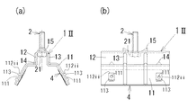
図1に示す本発明の持出部材1の第1実施例は、図3に示すように山状部分51と谷状部分52とが連続する屋根面5に設置する部材であり、山状部分51を構成する傾斜面に沿わせる脚部11と、山状部分51の頂部に配置して連結ボルト2の頭部21を収容する取付部12、を有し、前記脚部11には、固定具3が挿通する孔111と、該孔111の上方及び側方からの流水を防ぐ堰状部112とを設けてなる。
The first embodiment of the take-out
前記脚部11は、屋根面5の山状部分51を構成する傾斜面及び頂部に沿わせる部位を指し、左右の脚部11,11の間に、下方が開放する矩形状の取付部12が形成される形状であり、略矩形状の板材に適宜加工を加えて成形することができる構成である。
The said
図示実施例における脚部11は、下方に位置する傾斜面部と上方に位置する水平面部とからなる略く字状に形成され、そのうち、下方の傾斜面部には、孔111が二箇所に設けられ、各孔111の上方及び側方からの流水を防ぐ堰状部112が設けられている。この堰状部112は、裏面側に空間が形成される、上方へ突出する断面円弧状の隆状部にて形成され、プレス加工等にて形成することができ、連続する隆状部は平面視逆U字状に形成されている。また、この脚部11の傾斜面部の裏面には、シート状の止水ゴム4が添設されている。
なお、止水ゴム4を添設するのは、孔111を穿設する加工の後が望ましく、添設した時点では止水ゴム4には孔111が形成されていない方が固定具3を打ち込んだ際に防水性が保たれ易い。
The
The water stop rubber 4 is preferably attached after the process of making the
また、この持出部材1における取付部12は、略中央に位置する横片状の上面部と左右の略垂直面状の縦片部とからなり、その内部空間には、六角ボルトである連結ボルト2の頭部21が収容されている。
Further, the
また、図示実施例の持出部材1には、前記堰状部112と同様の加工にて、前記取付部12の縦片部から脚部11の傾斜面部まで連続する突状部が形成されているが、この突状部は部材の変形等を防止する補強用堰状部13である。
また、前記二つの孔111の上方に位置し、脚部11と前記取付部12との境には、三角形状の突状部14が設けられ、該突状部14に至った雨水を孔111の右又は左に流す役割を果たしている。
さらに、前記取付部12の上面部の中心部を挟んで流れ方向の前後を切り起こして規制部15,15を設けている。
Further, in the take-out
Further, a triangular projecting
Further, the regulating
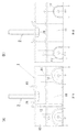
このような脚部11と取付部12とを有する持出部材1では、各孔111の周囲にそれぞれ堰状部112を形成しているので、図2(a)に矢印にて示すように上方や側方からの雨水は堰状部112によって迂回されて排水(流下)される。
In the take-out
また、図示実施例におけるこの堰状部112は、前述のように裏面に連続内部空間を有する構成であるため、その連続内部空間には、下端から毛細管現象にて雨水が浸入することがない。尤も、風雨の吹き上げ等により、この堰状部112の連続内部空間に下方から雨水が浸入することが全くない訳ではない。しかし、堰状部112の裏面側に吹き上げ風力にて雨水が浸入した場合にも、雨水は、図2(b)に矢印にて示すように、堰状部112の連続内側空間を回るだけで、孔111への浸入は生じない。
このように、固定具3によって形成される穿孔への雨水の浸入を前記堰状部112が防止することができる。
In addition, since the weir-shaped
In this way, the weir-
図3に示す太陽電池モジュールの取付構造は、前記持出部材1を山状部分51と谷状部分52とが連続する屋根面5に設置し、その取付部12の上面に直接的に外設部材6として太陽電池モジュールを取り付けてなる構成である。
In the solar cell module mounting structure shown in FIG. 3, the take-out
図示実施例の太陽電池モジュール6は、太陽電池60の周縁に所定形状のフレーム6bを一体的に固定したパネル状であって、この太陽電池モジュール6の流れ方向の側縁を、断面形状が逆ハット状の押さえ材7にて押さえた構成である。
この実施例における押さえ材7は、前述のように断面逆ハット状のピース材であり、前記連結ボルト2が挿通する通孔を有する底状部72の両側縁を立ち上げ、その上端を外方へ延在させて押さえ部71,71とした構成である。
The solar cell module 6 of the illustrated embodiment has a panel shape in which a
The
このような構成を有する太陽電池モジュール6の取付構造は、前記持出部材1の取付部12の上面に太陽電池モジュール6を取り付けた構成であり、山状部分51と谷状部分52とが連続する屋根面5に対し、太陽電池モジュール6を簡易な構造にて取り付けることができる。
しかも取付部12の上面には連結ボルト2が起立状に取り付けられているので、該連結ボルト2に押さえ材7を挿通させ、連結ボルト2の上端からナット2Nを嵌め付け、締め付けることにより、流れ方向に隣接する太陽電池モジュール6,6の側縁を押さえ材7の押さえ部71,71にて押さえ込むように固定することができる。
The mounting structure of the solar cell module 6 having such a configuration is a configuration in which the solar cell module 6 is mounted on the upper surface of the mounting
Moreover, since the connecting
なお、太陽電池モジュール6の取付は、前述のように前記持出部材1の取付部12の上面に、太陽電池モジュール6を配置し、その周縁を押さえ材7の押さえ部71にて押さえ付けるように取り付けるが、前述のように取付部12の上面には規制部15,15が設けられているので、太陽電池モジュール6(フレーム6b)の下端をこれらの規制部15,15に係止されるように配置すればよく、容易に位置決めがなされる。
The solar cell module 6 is attached in such a manner that the solar cell module 6 is disposed on the upper surface of the
図4に示す第2実施例の持出部材1IIは、脚部に設けた堰状部112iiが、孔を含む所定範囲をプレス加工等にて台状に隆起させた台状部113の段差にて形成されている以外は、前記図1の持出部材1と全く同様であるから、図面に同一符号を付して説明を省略する。なお、この台状部113は、下方の段差部分に排水口を設け、仮に裏面側の空間に雨水が浸入してもこの排水口から外側へ流下させることができる。
In the take-out member 1II of the second embodiment shown in FIG. 4, the weir-like portion 112ii provided on the leg portion is formed on the step of the base-
図5に示す第3実施例の持出部材1IIIは、脚部に設けた堰状部112iiiが、裏面側に空間を有する断面円弧状の隆状部にて形成され、プレス加工等にて形成できる点では、前記図1の持出部材1と同様であるが、連続する隆状部は平面視逆V字状に形成されている点が異なる。それ以外は、前記図1の持出部材1と全く同様であるから、図面に同一符号を付して説明を省略する。
In the take-out member 1III of the third embodiment shown in FIG. 5, the dam-like portion 112iii provided on the leg portion is formed as a ridge portion having a circular arc cross section having a space on the back surface side, and is formed by press working or the like. In the point which can be performed, it is the same as that of the taking-out
1,1II,1III 持出部材
11 脚部
111 孔
112,112ii,112iii 堰状部
12 取付部
13 補強用堰状部
14 突状部
15 規制部
2 連結ボルト
2N ナット
21 頭部
3 固定具
4 止水ゴム
5 屋根面
51 山状部分
52 谷状部分
6 外設部材(太陽電池モジュール)
60 太陽電池
6b フレーム
7 押さえ材
71 押さえ部
72 底状部
1, 1II, 1III Taking-
60
Claims (5)
山状部分を構成する左右の傾斜面にそれぞれ沿わせる脚部と、山状部分の頂部に外設部材又は外設部材を支持する支持材の取付部と、を有し、前記左右の脚部には、固定具が挿通する孔と、該孔の上方及び側方からの流水を防ぐ堰状部とをそれぞれ複数設けてなることを特徴とする持出部材。 It is a take-out member installed on a roof surface where a mountain-shaped portion and a valley-shaped portion are continuous,
Has a leg portion be along respective inclined surfaces of the right and left which constitutes the mountain-shaped portion, an attachment portion of the support member that supports the outer portion material or outer portion material to the top of the mountain-shaped portion, wherein the left and right legs The take-out member is characterized in that a plurality of holes through which the fixture is inserted and a weir-like portion that prevents water flowing from above and from the side of the hole are provided.
Priority Applications (1)
| Application Number | Priority Date | Filing Date | Title |
|---|---|---|---|
| JP2011221870A JP5777007B2 (en) | 2011-10-06 | 2011-10-06 | Bringing member and external member mounting structure using the same |
Applications Claiming Priority (1)
| Application Number | Priority Date | Filing Date | Title |
|---|---|---|---|
| JP2011221870A JP5777007B2 (en) | 2011-10-06 | 2011-10-06 | Bringing member and external member mounting structure using the same |
Publications (3)
| Publication Number | Publication Date |
|---|---|
| JP2013083044A JP2013083044A (en) | 2013-05-09 |
| JP2013083044A5 JP2013083044A5 (en) | 2014-03-20 |
| JP5777007B2 true JP5777007B2 (en) | 2015-09-09 |
Family
ID=48528486
Family Applications (1)
| Application Number | Title | Priority Date | Filing Date |
|---|---|---|---|
| JP2011221870A Active JP5777007B2 (en) | 2011-10-06 | 2011-10-06 | Bringing member and external member mounting structure using the same |
Country Status (1)
| Country | Link |
|---|---|
| JP (1) | JP5777007B2 (en) |
Families Citing this family (6)
| Publication number | Priority date | Publication date | Assignee | Title |
|---|---|---|---|---|
| JP6122359B2 (en) * | 2013-07-12 | 2017-04-26 | 奥地建産株式会社 | Fixing bracket for roof top article installation |
| JP6238616B2 (en) * | 2013-07-24 | 2017-11-29 | 奥地建産株式会社 | Plane article fixing bracket for goby type folded-plate roof |
| JP2015158063A (en) * | 2014-02-24 | 2015-09-03 | 元旦ビューティ工業株式会社 | Support member and support structure of outside material |
| JP6873430B2 (en) * | 2017-05-10 | 2021-05-19 | 鹿島建設株式会社 | Folded plate structure and mounting method |
| JP6714638B2 (en) * | 2018-04-26 | 2020-06-24 | 元旦ビューティ工業株式会社 | Support member and support structure for external material |
| JP6714639B2 (en) * | 2018-04-26 | 2020-06-24 | 元旦ビューティ工業株式会社 | Support member and support structure for external material |
Family Cites Families (4)
| Publication number | Priority date | Publication date | Assignee | Title |
|---|---|---|---|---|
| JP2003343047A (en) * | 2002-05-24 | 2003-12-03 | Masami Tanaka | Folded-plate roof construction |
| JP4400875B2 (en) * | 2004-08-09 | 2010-01-20 | 京セラ株式会社 | Solar power system |
| JP4959215B2 (en) * | 2006-04-14 | 2012-06-20 | 京セラ株式会社 | Fixing device |
| JP5404354B2 (en) * | 2009-12-04 | 2014-01-29 | 昭和シェル石油株式会社 | Draining structure for solar cell module |
-
2011
- 2011-10-06 JP JP2011221870A patent/JP5777007B2/en active Active
Also Published As
| Publication number | Publication date |
|---|---|
| JP2013083044A (en) | 2013-05-09 |
Similar Documents
| Publication | Publication Date | Title |
|---|---|---|
| JP5777007B2 (en) | Bringing member and external member mounting structure using the same | |
| CN101802324B (en) | Fixing structure of solar battery module, frame for the solar battery module, and fixing member | |
| JP5202430B2 (en) | Solar cell module fixing structure | |
| JP4400875B2 (en) | Solar power system | |
| JP4381634B2 (en) | Solar panel fixing device | |
| JP2012177291A (en) | Supporting apparatus | |
| JP2011038384A (en) | Panel for roof and mounting structure of panel for roof | |
| JP5577298B2 (en) | Solar module mounting bracket | |
| JP5788290B2 (en) | Roof fixing device | |
| JP5404354B2 (en) | Draining structure for solar cell module | |
| JP2018137962A (en) | Side frame for solar cell module | |
| JP2008095418A (en) | Sheathing construction support member, and sheathing structure using the support member | |
| JP5662003B2 (en) | Installation structure of solar cell module | |
| JP5479033B2 (en) | Roof structure | |
| JP5666325B2 (en) | Roof fixing device | |
| JP5893273B2 (en) | Lower layer structure of solar cell panel and exterior structure including solar cell panel | |
| JP5205250B2 (en) | Solar cell module mounting structure and mounting method | |
| JP5648995B2 (en) | Mounting structure of support frame and exterior structure | |
| JP2007217904A (en) | Solar battery module mounting method | |
| JP2011202504A (en) | Supporting member for exterior construction | |
| JP5880918B2 (en) | Solar panel laying structure | |
| JP2006274618A (en) | Securing structure for sunlight utilizing device | |
| JP2001027018A (en) | Structure for attaching solar battery panel to wooden house or the like | |
| JP5968115B2 (en) | Equipment fixing device | |
| JP2012151347A (en) | Photovoltaic power generation panel |
Legal Events
| Date | Code | Title | Description |
|---|---|---|---|
| A521 | Written amendment |
Free format text: JAPANESE INTERMEDIATE CODE: A523 Effective date: 20140204 |
|
| A621 | Written request for application examination |
Free format text: JAPANESE INTERMEDIATE CODE: A621 Effective date: 20140204 |
|
| A977 | Report on retrieval |
Free format text: JAPANESE INTERMEDIATE CODE: A971007 Effective date: 20141120 |
|
| A131 | Notification of reasons for refusal |
Free format text: JAPANESE INTERMEDIATE CODE: A131 Effective date: 20141202 |
|
| A521 | Written amendment |
Free format text: JAPANESE INTERMEDIATE CODE: A523 Effective date: 20150129 |
|
| TRDD | Decision of grant or rejection written | ||
| A01 | Written decision to grant a patent or to grant a registration (utility model) |
Free format text: JAPANESE INTERMEDIATE CODE: A01 Effective date: 20150609 |
|
| A61 | First payment of annual fees (during grant procedure) |
Free format text: JAPANESE INTERMEDIATE CODE: A61 Effective date: 20150626 |
|
| R150 | Certificate of patent (=grant) or registration of utility model |
Ref document number: 5777007 Country of ref document: JP Free format text: JAPANESE INTERMEDIATE CODE: R150 |