JP5776044B2 - Game machine - Google Patents
Game machine Download PDFInfo
- Publication number
- JP5776044B2 JP5776044B2 JP2011252167A JP2011252167A JP5776044B2 JP 5776044 B2 JP5776044 B2 JP 5776044B2 JP 2011252167 A JP2011252167 A JP 2011252167A JP 2011252167 A JP2011252167 A JP 2011252167A JP 5776044 B2 JP5776044 B2 JP 5776044B2
- Authority
- JP
- Japan
- Prior art keywords
- special
- game
- effect
- display
- mode
- Prior art date
- Legal status (The legal status is an assumption and is not a legal conclusion. Google has not performed a legal analysis and makes no representation as to the accuracy of the status listed.)
- Expired - Fee Related
Links
Images


Description
本発明は、複数の識別情報を変動表示する変動表示ゲームの始動権利を発生させる始動入賞領域と、変動表示ゲームの演出表示を行うための表示装置とを備え、始動入賞領域への遊技球の入賞に基づき前記変動表示ゲームを実行し、該変動表示ゲームの結果が予め定めた特別結果となったことに基づき遊技者に有利な特別遊技状態を発生させる遊技機に関する。 The present invention includes a start winning area for generating a start right for a variable display game that displays a plurality of identification information in a variable manner, and a display device for effect display of the variable display game. The present invention relates to a gaming machine that executes the variable display game based on a prize and generates a special gaming state advantageous to a player based on a result of the variable display game being determined in advance.
従来の遊技機、例えばパチンコ遊技機においては、始動条件の成立に基づき表示装置で複数の識別情報を変動表示する変動表示ゲームを実行し、該変動表示ゲームが予め定めた特別結果となった場合に遊技者に有利な特別遊技状態を発生させるものが知られている。この種の遊技機においては、変動表示ゲームの開始時に演出態様を決定し、該決定された演出態様により変動表示ゲームの演出を行うものが大多数を占めているが、その中には変動表示ゲームの実行中に複数の演出態様の何れかを遊技者に選択させ、該選択された演出態様により変動表示ゲームの演出を行うものも提案されている(例えば、特許文献1)。 In a conventional gaming machine, such as a pachinko gaming machine, when a variable display game is executed that displays a plurality of identification information on a display device based on the establishment of a start condition, and the variable display game has a predetermined special result In addition, there is known one that generates a special gaming state advantageous to a player. In this type of gaming machine, the majority of the machines that determine the effect mode at the start of the variable display game and perform the variable display game according to the determined effect mode are included. It has also been proposed to cause a player to select one of a plurality of effect modes during the execution of a game, and to perform a variable display game effect according to the selected effect mode (for example, Patent Document 1).
ところで、上記した特許文献1に開示された遊技機においては、遊技演出が単調となってしまって遊技者が飽きてしまうという問題があった。
By the way, in the gaming machine disclosed in
本発明の目的は、複数の識別情報を変動表示する変動表示ゲームの始動権利を発生させる始動入賞領域と、変動表示ゲームの演出表示を行うための表示装置とを備え、始動入賞領域への遊技球の入賞に基づき変動表示ゲームを実行し、該変動表示ゲームの結果が予め定めた特別結果となったことに基づき遊技者に有利な特別遊技状態を発生させる遊技機において、遊技者を飽きさせることなく変動表示ゲームを繰り返し実行することが可能な興趣の高い遊技機を提供することである。 An object of the present invention is provided with a start winning area for generating a start right for a variable display game that displays a plurality of identification information in a variable manner, and a display device for effect display of the variable display game. A player is bored in a gaming machine that executes a variable display game based on a winning of a ball and generates a special gaming state advantageous to the player based on the result of the variable display game being a predetermined special result. It is an object to provide an amusing gaming machine capable of repeatedly executing a variable display game without any problems.
以上の課題を解決するため、請求項1に記載の発明は、複数の識別情報を変動表示する変動表示ゲームの始動権利を発生させる始動入賞領域と、前記変動表示ゲームの演出表示を行うための表示装置とを備え、
前記始動入賞領域への遊技球の入賞に基づき前記変動表示ゲームを実行し、該変動表示ゲームの結果が予め定めた特別結果となったことに基づき遊技者に有利な特別遊技状態を発生させる遊技機において、
遊技者が所定の切替操作を行うことが可能な操作部と、
前記識別情報を変動表示するための複数の変動パターンの何れかによって前記変動表示ゲームを実行することが可能な変動表示ゲーム実行手段と、
前記変動表示ゲーム実行手段が実行する変動パターンに対応する複数の演出態様の何れかにより前記演出表示を実行することが可能な演出表示手段と、
前記変動表示ゲーム中の前記切替操作に基づき、前記演出表示手段が実行中の演出表示の演出態様を切り替えることが可能な演出態様切替手段と、を備え、
前記変動パターンには、前記演出表示に単一の演出態様が対応付けられた第1変動パターンと、前記演出表示に複数の演出態様が対応付けられた第2変動パターンとを含み、
前記演出態様切替手段は、前記第2変動パターンによる演出表示が実行されている場合に、当該演出表示の演出態様を実行中の変動パターンに対応する他の演出態様に切り替え可能であり、
前記第2変動パターンにおける前記複数の演出態様は、
同一のストーリーについて対峙する複数の側からの視点に基づいて並行的に進行する演出であり、
前記演出態様切替手段によって、一方の側の視点に基づく演出態様から対峙する他方の側の視点に基づく演出態様に切り替えられ、
前記変動表示ゲームの結果と前記ストーリーの結末とが対応するように構成され、当該結末を各側からの視点で示すことを特徴とする。
In order to solve the above-described problems, the invention described in
A game in which the variable display game is executed based on a winning of a game ball in the start winning area, and a special game state advantageous to the player is generated based on a result of the variable display game being a predetermined special result. In the machine
An operation unit that allows a player to perform a predetermined switching operation;
A variation display game executing means capable of executing the variation display game according to any of a plurality of variation patterns for variably displaying the identification information;
Effect display means capable of executing the effect display according to any of a plurality of effect modes corresponding to the change pattern executed by the change display game executing means;
Effect mode switching means capable of switching the effect mode of the effect display being executed by the effect display means based on the switching operation during the variable display game,
The variation pattern includes a first variation pattern in which a single effect mode is associated with the effect display, and a second variation pattern in which a plurality of effect modes are associated with the effect display,
The effect mode switching means can switch the effect mode of the effect display to another effect mode corresponding to the variation pattern being executed when the effect display by the second variation pattern is being executed .
The plurality of effects in the second variation pattern are:
It is a production that progresses in parallel based on viewpoints from multiple sides facing the same story,
The production mode switching means switches from the production mode based on the viewpoint on one side to the production mode based on the viewpoint on the other side facing each other.
The result of the variable display game and the ending of the story are configured to correspond to each other, and the ending is shown from a viewpoint from each side .
ここで、操作部は、遊技者の操作を受け付けることができるものであれば何でも良く、ボタンやタッチセンサ、所定空間内での遊技者の手の動きを検出可能なセンサなどが挙げられる。 Here, the operation unit may be anything as long as it can accept the player's operation, and examples thereof include a button, a touch sensor, and a sensor that can detect the movement of the player's hand in the predetermined space.
請求項1に記載の発明によれば、遊技者の切替操作により演出表示態様が切り替わるので、遊技者を飽きさせることなく変動表示ゲームを繰り返し実行することが可能となり、遊技の興趣が向上する。また、変動パターンの種類によって演出態様の切替制御の可否を設定しておくことで、演出態様の切替制御の制御負荷を軽減することができる。 According to the first aspect of the present invention, the effect display mode is switched by the switching operation of the player, so that the variable display game can be repeatedly executed without getting the player bored, and the interest of the game is improved. Further, by setting whether or not the effect mode switching control is possible depending on the type of the variation pattern, the control load of the effect mode switching control can be reduced.
請求項2に記載の発明は、請求項1に記載の遊技機であって、前記演出表示は、前記表示装置の表示部に主として表示されるメイン演出表示と、該表示部の一部に縮小表示されるサブ演出表示とを含み、
前記演出表示手段は、実行中の演出表示をメイン演出表示として表示する一方、切替候補となる前記他の演出態様をサブ演出表示として表示し、
前記演出態様切替手段は、前記演出表示手段が前記表示部に表示している前記メイン演出表示と前記サブ演出表示とを入れ替えさせることで前記演出態様を切り替え可能であり、
前記サブ演出表示は所定の枠内に表示され、前記枠の態様により前記特別結果となる可能性を報知することを特徴とする。
The invention according to
The effect display means displays the effect display being executed as the main effect display, while displaying the other effect modes as the switching candidates as the sub effect display,
The effect mode switching means can switch the effect mode by switching the main effect display and the sub effect display displayed on the display unit by the effect display means ,
The sub-effect display is displayed in a predetermined frame, and the possibility of the special result is notified by the form of the frame .
請求項2に記載の発明によれば、サブ演出表示により遊技者が切替後の演出態様を即座
に把握することができ、切替操作により任意の演出態様を選択することが可能となる。
According to the second aspect of the present invention, the player can immediately grasp the effect mode after switching by the sub effect display, and can select any effect mode by the switching operation.
本発明によれば、遊技者の切替操作により演出表示態様が切り替わるので、遊技者を飽きさせることなく変動表示ゲームを繰り返し実行することが可能となり、遊技の興趣が向上する。 According to the present invention, since the effect display mode is switched by the switching operation of the player, the variable display game can be repeatedly executed without getting the player bored, and the interest of the game is improved .
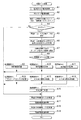
以下、本発明の好適な実施の形態を図面に基づいて説明する。図1は、本発明の一実施形態の遊技機の説明図である。 DESCRIPTION OF EXEMPLARY EMBODIMENTS Hereinafter, preferred embodiments of the invention will be described with reference to the drawings. FIG. 1 is an explanatory diagram of a gaming machine according to an embodiment of the present invention.
本実施形態の遊技機10は前面枠12を備え、該前面枠12は本体枠(外枠)11にヒンジ13を介して開閉回動可能に組み付けられている。遊技盤30(図2参照)は前面枠12の表側に形成された収納部(図示省略)に収納されている。また、前面枠(内枠)12には、遊技盤30の前面を覆うカバーガラス(透明部材)14を備えたガラス枠15が開閉可能に取り付けられている。
The
また、ガラス枠15の上部には、ランプ及びモータを内蔵した照明装置(ムービングライト)16や払出異常報知用のランプ(LED)17が設けられている。また、ガラス枠15の左右にはランプ等を内蔵し装飾や演出のための発光をする枠装飾装置18や、音響(例えば、効果音)を発するスピーカ(上スピーカ)19aが設けられている。さらに、前面枠12の下部にもスピーカ(下スピーカ)19bが設けられている。
Further, an illuminating device (moving light) 16 incorporating a lamp and a motor and a lamp (LED) 17 for notifying a dispensing abnormality are provided on the upper part of the
また、前面枠12の下部には、図示しない打球発射装置に遊技球を供給する上皿21、遊技機10の裏面側に設けられている球払出装置から払い出された遊技球が流出する上皿球出口22、上皿21が一杯になった状態で払い出された遊技球を貯留する下皿23、打球発射装置の操作部24等が設けられている。さらに、上皿21の上縁部には、遊技者からの操作入力を受け付けるための操作スイッチを内蔵した操作部をなす演出ボタン25が設けられている。さらに、前面枠12下部右側には、前面枠12を開放したり施錠したりするための鍵26が設けられている。
In addition, at the lower part of the
この実施形態の遊技機10においては、遊技者が上記操作部24を回動操作することによって、打球発射装置が、上皿21から供給される遊技球を遊技盤30前面の遊技領域32(図2参照)に向かって発射する。また、遊技者が演出ボタン25を操作することによって、表示装置41(図2参照)における変動表示ゲーム(飾り特図変動表示ゲーム)において、遊技者の操作を介入させた演出等を行わせることができる。さらに、上皿21上方のガラス枠15の前面には、遊技者が隣接する球貸機から球貸しを受ける場合に操作する球貸ボタン27、球貸機のカードユニットからプリペイドカードを排出させるために操作する排出ボタン28、プリペイドカードの残高を表示する残高表示部(図示省略)等が設けられている。
In the
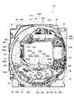
次に、図2を用いて遊技盤30の一例について説明する。図2は、本実施形態の遊技盤30の正面図である。
Next, an example of the
遊技盤30の表面には、ガイドレール31で囲われた略円形状の遊技領域32が形成されている。遊技領域32は、遊技盤30の四隅に各々設けられた樹脂製のサイドケース33及びガイドレール31に囲繞されて構成される。遊技領域32には、ほぼ中央に表示装置41を備えた包囲枠体(センターケース)40が配置されている。表示装置41は、包囲枠体40に設けられた凹部に、当該包囲枠体40の前面より奥まった位置に取り付けられている。すなわち、包囲枠体40は表示装置41の表示領域Rの周囲を囲い、表示装置41の表示面よりも前方へ突出し周囲の遊技領域32から遊技球が飛び込みにくくするように形成されている。
On the surface of the
表示装置41は、例えば、LCD(液晶表示器)、CRT(ブラウン管)等の表示画面を有する装置で構成されている。表示画面の画像を表示可能な領域(表示領域R、表示部)には、複数の識別情報(特別図柄)や特図変動表示ゲームを演出するキャラクタや演出効果を高める背景画像等の遊技に関する情報が表示される。表示装置41の表示画面においては、識別情報として割り当てられた複数の特別図柄が変動表示(可変表示)されて、特図変動表示ゲームに対応した飾り特図変動表示ゲームが行われる。また、表示画面には遊技の進行に基づく演出のための画像(例えば、大当り表示画像、ファンファーレ表示画像、エンディング表示画像等)が表示される。
The
遊技領域32の包囲枠体40の左側等には、普通図柄始動ゲート(普図始動ゲート)34が設けられている。包囲枠体40の左下側には、三つの一般入賞口35が配置され、包囲枠体40の右下側には、一つの一般入賞口35が配置されている。これら一般入賞口35、…には、各一般入賞口35に入賞した遊技球を検出するための入賞口スイッチ35a(図10参照)が配設されている。
A normal symbol start gate (ordinary start gate) 34 is provided on the left side of the surrounding
また、包囲枠体40の下方には、特図変動表示ゲームの開始条件を与える始動入賞口36(第1始動入賞口)が設けられ、その直下には上部に逆「ハ」の字状に開いて遊技球が流入し易い状態に変換する一対の可動部材37b,37bを備えるとともに内部に第2始動入賞口を有する普通変動入賞装置(普電)37が配設されている。
In addition, a start winning opening 36 (first start winning opening) for providing a start condition of the special figure variation display game is provided below the surrounding
普通変動入賞装置37の一対の可動部材37b,37bは、常時は遊技球の直径程度の間隔をおいて閉じた閉状態(遊技者にとって不利な状態)を保持している。ただし、普通変動入賞装置37の上方には、始動入賞口36が設けられているので、閉じた状態では遊技球が入賞できないようになっている。そして、普図変動表示ゲームの結果が所定の停止表示態様となった場合には、駆動装置としての普電ソレノイド37c(図10参照)によって、逆「ハ」の字状に開いて普通変動入賞装置37に遊技球が流入し易い開状態(遊技者にとって有利な状態)に変化させられるようになっている。
The pair of
また、遊技機10は、特図変動表示ゲームの結果によって遊技球を受け入れない状態と受け入れ易い状態とに変換可能な第1特別変動入賞装置(大入賞口)38と、第2特別変動入賞装置(大入賞口)39とを備えている。
In addition, the
第1特別変動入賞装置38は、普通変動入賞装置37の下方に配設されている。そして、第1特別変動入賞装置38は、上端側が手前側に倒れる方向に回動して開放可能になっているアタッカー形式の開閉扉38cを有しており、補助遊技としての特図変動表示ゲームの結果如何によって大入賞口を閉じた状態(遊技者にとって不利な閉塞状態)から開放状態(遊技者にとって有利な状態)に変換する。すなわち、第1特別変動入賞装置38は、例えば、駆動装置としての大入賞口ソレノイド38b(図10参照)により駆動される開閉扉38cによって開閉される大入賞口を備え、特別遊技状態中は、大入賞口を閉じた状態から開いた状態に変換することにより大入賞口内への遊技球の流入を容易にさせ、遊技者に所定の遊技価値(賞球)を付与するようになっている。なお、第1特別変動入賞装置(大入賞口)38の内部(入賞領域)には、当該大入賞口に入った遊技球を検出する検出手段としてのカウントスイッチ38a(図10参照)が配設されている。第1特別変動入賞装置38の下方には、入賞口などに入賞しなかった遊技球を回収するアウト口32aが設けられている。
The first special variable winning
第2特別変動入賞装置39は、包囲枠体40の上部左側に配設されている。そして、第2特別変動入賞装置39は、上端側が左側に倒れる方向に回動して開放可能になっているアタッカー形式の開閉部材39cを有しており、補助遊技としての特図変動表示ゲームの結果如何によって大入賞口を閉じた状態(遊技者にとって不利な閉塞状態)から開放状態(遊技者にとって有利な状態)に変換する。すなわち、第2特別変動入賞装置39は、例えば、駆動装置としての大入賞口ソレノイド39b(図10参照)により駆動される開閉部材39cによって開閉される大入賞口を備え、特別遊技状態中は、大入賞口を閉じた状態から開いた状態に変換することにより大入賞口内への遊技球の流入を容易にさせ、遊技者に所定の遊技価値(賞球)を付与するようになっている。なお、第2特別変動入賞装置(大入賞口)39の内部(入賞領域)には、当該大入賞口に入った遊技球を検出する検出手段としてのカウントスイッチ39a(図10参照)が配設されている。
The second special
また、遊技領域32の外側(例えば、遊技盤30の右下部)には、特図変動表示ゲームをなす第1特図変動表示ゲームや第2特図変動表示ゲーム及び普図始動ゲート34への入賞をトリガとする普図変動表示ゲームを一箇所で実行する一括表示装置50が設けられている。
In addition, on the outside of the game area 32 (for example, in the lower right part of the game board 30), the first special figure fluctuation display game, the second special figure fluctuation display game, and the general figure start
一括表示装置50は、7セグメント型の表示器(LEDランプ)等で構成された第1特図変動表示ゲーム用の第1特図変動表示部(特図1表示器)及び第2特図変動表示ゲーム用の第2特図変動表示部(特図2表示器)と、LEDランプで構成された普図変動表示ゲーム用の変動表示部(普図表示器)と、同じくLEDランプで構成された各変動表示ゲームの始動記憶数報知用の記憶表示部とを備える。また、一括表示装置50には、大当りが発生すると点灯して大当り発生を報知する第1遊技状態表示部(第1遊技状態表示器)、時短状態が発生すると点灯して時短状態発生を報知する第2遊技状態表示部(第2遊技状態表示器)、遊技機10の電源投入時に大当りの確率状態が高確率状態となっていることを表示する確率状態表示部(第3遊技状態表示器)、大当り時のラウンド数(特別変動入賞装置38、39の開閉回数)を表示するラウンド表示部が設けられている。
The
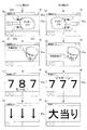
特図1表示器と特図2表示器における特図変動表示ゲームは、例えば変動表示ゲームの実行中、すなわち、表示装置41において飾り特図変動表示ゲームを行っている間は、中央のセグメントを点滅駆動させて変動中であることを表示する。そして、ゲームの結果が「はずれ」のときは、はずれの結果態様として例えば中央のセグメントを点灯状態にし、ゲームの結果が「当り」のときは、当りの結果態様(特別結果態様)としてはずれの結果態様以外の結果態様(例えば、「3」や「7」の数字)を点灯状態にしてゲーム結果を表示する。
The special figure fluctuation display game in the special figure 1 display and the special figure 2 display is, for example, during the execution of the fluctuation display game, that is, while the decoration special figure fluctuation display game is being performed on the
普図表示器は、変動中はランプを点滅させて変動中であることを表示する。そして、ゲームの結果が「はずれ」のときは、例えばランプを消灯状態にし、ゲームの結果が「当り」のときはランプを点灯状態にしてゲーム結果を表示する。 The universal display displays the fact that the light is changing by blinking the lamp during the change. When the game result is “out of”, for example, the lamp is turned off, and when the game result is “hit”, the lamp is turned on to display the game result.
特図1保留表示器は、特図1表示器の変動開始条件となる始動入賞口36への入賞球数のうち未消化の球数(始動記憶数=保留数)を表示する。具体的には、保留数が「0」のときは4つのランプを全て消灯状態にし、保留数が「1」のときはランプ1のみを点灯状態にする。また、保留数が「2」のときはランプ1と2を点灯状態にし、保留数が「3」のときはランプ1と2と3を点灯状態にし、保留数が「4」のときは4つのランプ1〜4をすべて点灯状態にする。特図2保留表示器は、特図2表示器の変動開始条件となる第2始動入賞口(普通変動入賞装置37)の始動記憶数(=保留数)を、特図1保留表示器と同様にして表示する。
The special figure 1 hold indicator displays the number of undigested balls (starting memory number = holding number) among the number of winning balls to the start winning
普図保留表示器は、普図表示器の変動開始条件となる普図始動ゲート34の始動記憶数(=保留数)を表示する。例えば保留数が「0」のときはランプ1と2を消灯状態にし、保留数が「1」のときはランプ1のみを点灯状態にする。また、保留数が「2」のときはランプ1と2を点灯状態にし、保留数が「3」のときはランプ1を点滅、ランプ2を点灯状態にし、保留数が「4」のときはランプ1と2を点滅状態にする。
The general map hold indicator displays the start memory number (= hold number) of the general map start
第1遊技状態表示器は、例えば通常の遊技状態の場合にはランプを消灯状態にし、大当りが発生している場合にはランプを点灯状態にする。第2遊技状態表示器は、例えば通常の遊技状態の場合にはランプを消灯状態にし、時短状態が発生している場合にはランプを点灯状態にする。 For example, the first game state indicator turns off the lamp in a normal gaming state and turns on the lamp when a big hit has occurred. For example, the second gaming state indicator turns off the lamp in the normal gaming state, and turns on the lamp when the time-short state occurs.
確率状態表示部は、例えば遊技機10の電源投入時に大当りの確率状態が低確率状態の場合にはランプを消灯状態にし、遊技機10の電源投入時に大当りの確率状態が高確率状態の場合にはランプを点灯状態にする。
For example, the probability state display unit turns off the lamp when the jackpot probability state is a low probability state when the
ラウンド表示部は、例えば、通常の遊技状態の場合にはランプを消灯状態にし、大当りが発生した場合にはその大当りのラウンド数に対応するランプを点灯状態にする。なお、ラウンド表示部は7セグメント型の表示器で構成してもよい。 For example, the round display unit turns off the lamp in the normal gaming state, and turns on the lamp corresponding to the number of rounds of the big hit when the big hit occurs. Note that the round display unit may be a seven-segment display.
本実施形態の遊技機10では、図示しない発射装置から遊技領域32に向けて遊技球(パチンコ球)が打ち出されることによって遊技が行われる。打ち出された遊技球は、遊技領域32内の各所に配置された障害釘や風車等の方向転換部材によって転動方向を変えながら遊技領域32を流下し、普図始動ゲート34、一般入賞口35、始動入賞口36、普通変動入賞装置37又は特別変動入賞装置38、39に入賞するか、遊技領域32の最下部に設けられたアウト口32aへ流入し遊技領域32から排出される。そして、一般入賞口35、始動入賞口36、普通変動入賞装置37又は特別変動入賞装置38、39に遊技球が入賞すると、入賞した入賞口の種類に応じた数の賞球が、払出制御装置200(図10参照)によって制御される払出ユニットから、前面枠12の上皿21又は下皿23に排出される。
In the
一方、普図始動ゲート34内には、該普図始動ゲート34を通過した遊技球を検出するための非接触型のスイッチなどからなるゲートスイッチ34a(図10参照)が設けられており、遊技領域32内に打ち込まれた遊技球が普図始動ゲート34内を通過すると、ゲートスイッチ34aにより検出されて普図変動表示ゲームが行われる。また、普図変動表示ゲームを開始できない状態、例えば、既に普図変動表示ゲームが行われ、その普図変動表示ゲームが終了していない状態や、普図変動表示ゲームが当って普通変動入賞装置37が開状態に変換されている場合に、普図始動ゲート34を遊技球が通過すると、普図始動記憶数の上限数(例えば、4個)未満ならば、普図始動記憶数が加算(+1)されて普図始動記憶が1つ記憶されることとなる。この普図始動入賞の記憶数は、一括表示装置50の普図保留表示器に表示される。また、普図始動記憶には、普図変動表示ゲームの当りはずれを決定するための当り判定用乱数値が記憶されるようになっていて、この当り判定用乱数値が判定値と一致した場合に、当該普図変動表示ゲームが当りとなって特定の結果態様(普図特定結果)が導出されることとなる。
On the other hand, a
普図変動表示ゲームは、一括表示装置50に設けられた変動表示部(普図表示器)で実行されるようになっている。普図表示器は、普通識別情報(普図、普通図柄)として点灯状態の場合に当りを示し、消灯状態の場合にはずれを示すLEDから構成され、このLEDを点滅表示することで普通識別情報の変動表示を行い、所定の変動表示時間の経過後、LEDを点灯又は消灯することで結果を表示するようになっている。なお、普通識別情報として例えば数字、記号、キャラクタ図柄などを用い、これを所定時間変動表示させた後、停止表示させることにより行うように構成しても良い。この普図変動表示ゲームの停止表示が普図特定結果となれば、普図の当りとなって、普通変動入賞装置37の一対の可動部材37bが所定時間(例えば、普図低確率状態ならば0.3秒間、普図高確率状態ならば0.8秒間)開放される開状態となる。これにより、普通変動入賞装置37の内部の第2始動入賞口へ遊技球が入賞し易くなり、第2特図変動表示ゲームが実行される回数が多くなる。
The usual map variation display game is executed by a variation display unit (common diagram display) provided in the
普図始動ゲート34への通過検出時に抽出した普図乱数値が当り値であるときには、普図表示器に表示される普通図柄が当り状態で停止し、当り状態となる。このとき、普通変動入賞装置37は、内蔵されている普電ソレノイド37c(図10参照)が駆動されることにより、可動部材37bが所定の時間(例えば、普図低確率状態ならば0.3秒間、普図高確率状態ならば0.8秒間)だけ開放する状態に変換され、遊技球の入賞が許容される。
When the random number value extracted at the time of detection of the passage to the universal figure start
始動入賞口36への入賞球及び普通変動入賞装置37への入賞球は、それぞれは内部に設けられた始動口1スイッチ36aと始動口2スイッチ37aによって検出される。始動入賞口36へ入賞した遊技球は第1特図変動表示ゲームの始動入賞球として検出され、第1始動記憶として所定の上限数(例えば、4個)を限度に記憶されるとともに、普通変動入賞装置37へ入賞した遊技球は第2特図変動表示ゲームの始動入賞球として検出され、第2始動記憶として所定の上限数(例えば、4個)を限度に記憶される。また、この始動入賞球の検出時にそれぞれ大当り乱数値や大当り図柄乱数値、並びに各変動パターン乱数値が抽出され、抽出された乱数値は、遊技制御装置100(図10参照)内の特図記憶領域(RAMの一部)に特図始動記憶として各々所定回数(例えば、最大で4回分)を限度に記憶される。そして、この特図始動記憶の記憶数は、一括表示装置50の始動入賞数報知用の記憶表示部(特図1保留表示器、特図2保留表示器)に表示されるとともに、包囲枠体40の表示装置41においても飾り特図始動記憶表示m(図34参照)として表示される。
The winning ball to the
遊技制御装置100は、始動入賞口36若しくは普通変動入賞装置37への入賞、又はそれらの始動記憶に基づいて、特図1表示器(変動表示装置)又は特図2表示器(変動表示装置)で第1又は第2特図変動表示ゲームを行う。第1特図変動表示ゲーム及び第2特図変動表示ゲームは、複数の特別図柄(特図、識別情報)を変動表示したのち、所定の結果態様を停止表示することで行われる。また、各特図変動表示ゲームに対応して、表示装置(画像表示装置)41にて複数種類の識別情報(例えば、数字、記号、キャラクタ図柄等)を変動表示させるとともに、包囲枠体40に設けられた左上発光装置621、左下発光装置622、右上発光装置623、右下発光装置624における変化表示部673(図9参照)のLEDの点滅を行う飾り特図変動表示ゲームが実行されるようになっている。そして、特図変動表示ゲームの結果として、特図1表示器若しくは特図2表示器の表示態様が特別結果態様(特別結果)となった場合には、大当りとなって特別遊技状態(いわゆる、大当り状態)となる。また、これに対応して表示装置41と左上発光装置621、左下発光装置622、右上発光装置623、右下発光装置624における変化表示部673での停止態様からなる結果態様も特別結果態様となる(図45、図46参照)。
The
表示装置41及び左上発光装置621、左下発光装置622、右上発光装置623、右下発光装置624における飾り特図変動表示ゲームは、例えば、表示装置41において前述した数字等で構成される飾り特別図柄(識別情報)を左変動表示領域(第1特別図柄)、右変動表示領域(第2特別図柄)、中変動表示領域(第3特別図柄)のそれぞれにおいて各図柄を識別困難な速さで変動表示(高速変動)するとともに左上発光装置621、左下発光装置622、右上発光装置623、右下発光装置624における変化表示部673のLEDの点滅を行う。そして、所定時間後に変動している図柄を左変動表示領域、右変動表示領域、中変動表示領域の順に順次停止させるとともに左上発光装置621、左下発光装置622、右上発光装置623、右下発光装置624における変化表示部673のLEDの点滅を終了する。このときの左変動表示領域、右変動表示領域、中変動表示領域の各々で停止表示された識別情報と、左上発光装置621、左下発光装置622、右上発光装置623、右下発光装置624のそれぞれにおける変化表示部673のLEDの点灯又は点滅とにより構成される結果態様により特図変動表示ゲームの結果を表示することで行われる。また、表示装置41では、特図始動記憶数に対応する飾り特別図柄による変動表示ゲームを行うとともに、興趣向上のためにキャラクタの出現など多様な演出表示が行われる。
The decorative special figure variation display game in the
なお、特図1表示器、特図2表示器は、別々の表示器でも良いし同一の表示器でも良いが、各々独立して、また、同時には実行しないように各特図変動表示ゲームが表示される。また、表示装置41も、第1特図変動表示ゲームと第2特図変動表示ゲームで別々の表示装置や別々の表示領域を使用するとしても良いし、同一の表示装置や表示領域を使用するとしても良いが、各々独立して、また、同時には実行しないように飾り特図変動表示ゲームが表示される。また、遊技機10に特図1表示器、特図2表示器を備えずに、表示装置41のみで特図変動表示ゲームを実行するようにしても良い。また、第2特図変動表示ゲームは、第1特図変動表示ゲームよりも優先して実行されるようになっている。すなわち、第1特図変動表示ゲームと第2特図変動表示ゲームの始動記憶がある場合であって、特図変動表示ゲームの実行が可能となった場合は、第2特図変動表示ゲームが実行されるようになっている。
Note that the special figure 1 display and the special figure 2 display may be separate displays or the same display, but each special figure variation display game is not to be executed independently or simultaneously. Is displayed. In addition, the
また、第1特図変動表示ゲーム(第2特図変動表示ゲーム)が開始可能な状態で、且つ、始動記憶数が0の状態で、始動入賞口36(若しくは、普通変動入賞装置37)に遊技球が入賞すると、始動権利の発生に伴って始動記憶が記憶されて、始動記憶数が1加算されるととともに、直ちに始動記憶に基づいて、第1特図変動表示ゲーム(第2特図変動表示ゲーム)が開始され、この際に始動記憶数が1減算される。一方、第1特図変動表示ゲーム(第2特図変動表示ゲーム)が直ちに開始できない状態、例えば、既に第1若しくは第2特図変動表示ゲームが行われ、その特図変動表示ゲームが終了していない状態や、特別遊技状態となっている場合に、始動入賞口36(若しくは、普通変動入賞装置37)に遊技球が入賞すると、始動記憶数が上限数未満ならば、始動記憶数が1加算されて始動記憶が1つ記憶されることになる。そして、始動記憶数が1以上となった状態で、第1特図変動表示ゲーム(第2特図変動表示ゲーム)が開始可能な状態(前回の特図変動表示ゲームの終了若しくは特別遊技状態の終了)となると、始動記憶数が1減算されるとともに、記憶された始動記憶に基づいて第1特図変動表示ゲーム(第2特図変動表示ゲーム)が開始される。以下の説明において、第1特図変動表示ゲームと第2特図変動表示ゲームを区別しない場合は、単に特図変動表示ゲームと称する。 In addition, in the state where the first special figure fluctuation display game (second special figure fluctuation display game) can be started and the number of start memories is zero, the start winning opening 36 (or the normal fluctuation prize winning device 37) is entered. When the game ball wins, the start memory is stored as the start right is generated, the start memory number is incremented by 1, and the first special figure variation display game (second special figure) is immediately added based on the start memory. (Variable display game) is started, and at this time, the start memory number is decremented by one. On the other hand, a state in which the first special figure fluctuation display game (second special figure fluctuation display game) cannot be started immediately, for example, the first or second special figure fluctuation display game has already been performed, and the special figure fluctuation display game has ended. If the game ball is won in the start winning opening 36 (or the normal variable prize winning device 37) in a state that is not in the special game state or in the special game state, the start memory number is 1 if the start memory number is less than the upper limit number. By adding, one start memory is stored. Then, in a state where the starting memory number becomes 1 or more, a state in which the first special figure fluctuation display game (second special figure fluctuation display game) can be started (the end of the previous special figure fluctuation display game or the special game state) (End), the start memory number is decremented by 1, and the first special figure fluctuation display game (second special figure fluctuation display game) is started based on the stored start memory. In the following description, when the first special figure fluctuation display game and the second special figure fluctuation display game are not distinguished, they are simply referred to as a special figure fluctuation display game.
なお、特に限定されるわけではないが、上記始動入賞口36内の始動口1スイッチ36a、普通変動入賞装置37内の始動口2スイッチ37a、ゲートスイッチ34a、一般入賞口スイッチ35a、カウントスイッチ38a,39aには、磁気検出用のコイルを備え該コイルに金属が近接すると磁界が変化する現象を利用して遊技球を検出する非接触型の磁気近接センサ(以下、近接スイッチと称する)が使用されている。また、遊技機10のガラス枠15等に設けられた前枠開放検出スイッチ63や前面枠(遊技枠)12等に設けられた遊技枠開放検出スイッチ64には、機械的な接点を有するマイクロスイッチを用いることができる。
Although not particularly limited, the starting
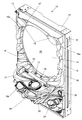
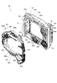
次に、図2、図3を参照して包囲枠体(所謂センターケース)40の詳細な構造について説明する。図3は、包囲枠体40を前面側から見た分解斜視図である。包囲枠体40は、表示装置41等を備える裏面構成部材(制御ユニット)700と、裏面構成部材700の前面に装着される前面構成部材(前側飾りユニット)600と、からなる。
Next, the detailed structure of the surrounding frame body (so-called center case) 40 will be described with reference to FIGS. FIG. 3 is an exploded perspective view of the
前面構成部材600は、開口部600aが形成された枠状をなしており、当該前面構成部材600の下部に、遊技球を転動させてから包囲枠体40の下方に流下させるステージ601を備えている。ステージ601には、当該ステージ601上の遊技球が転動する領域と前面構成部材600の開口部600aとを仕切る仕切り部材602や、当該ステージ601上を転動する遊技球を包囲枠体40の下方に流下させることが可能な誘導流路603が設けられている。
The
図2に示すように、仕切り部材602は、主に、少なくとも遊技球が転動可能な間隔をあけてステージ601の上面と対向するように配設された庇部602aと、庇部602aの下面後端部からステージ601の上面後端部に亘って配設された奥壁部602bと、を備えて構成される。
As shown in FIG. 2, the
誘導流路603は、仕切り部材602の奥壁部602bの前面略中央部からステージ601の前面略中央部に亘って設けられ、包囲枠体40の内部(ステージ601と庇部602aとの間)に向けて開口する誘導導入口603aと、ステージ601の前面のうち始動入賞口36の上方となる部分(具体的には、ステージ601の前面略中央部)に設けられ包囲枠体40の外部に向けて開口する誘導導出口603bと、を有し、当該誘導導入口603aと当該誘導導出口603bとを連通する流路である。すなわち、ステージ601は、誘導流路603によって、包囲枠体40の内部に開設された誘導導入口603aに流入した遊技球を包囲枠体40の前面に開設された誘導導出口603bを介して包囲枠体40の外部の始動入賞口36の直上方へ誘導できるよう構成されている。
The
また、前面構成部材600は、当該前面構成部材600の左部に、遊技領域32を流下する遊技球を包囲枠体40の内部へ誘導することが可能なワープ流路604を備えている。ワープ流路604は、前面構成部材600の左部上側に設けられ包囲枠体40の外部に向けて開口するワープ入口604aと、前面構成部材600の左部下側に設けられ包囲枠体40の内部(具体的には、ステージ601と庇部602aとの間)に向けて開口するワープ出口604bと、を有し、当該ワープ入口604aと当該ワープ出口604bとを連通する流路である。すなわち、前面構成部材600は、ワープ流路604によって、包囲枠体40の左側面に開設されたワープ入口604aに流入した遊技球を包囲枠体40の内部に開設されたワープ出口604bを介して包囲枠体40の内部のステージ601上(球転動部)へ誘導できるよう構成されている。
The
このように、遊技機10は、遊技盤30に形成される遊技領域32に臨む前面開口凹室状の包囲枠体40と、遊技領域32のうち包囲枠体40の下方に位置する部分に配設される入賞口(始動入賞口36)と、遊技球が転動可能なステージ601と、遊技領域32を流下する遊技球をステージ601へ誘導することが可能なワープ流路604と、ステージ601を転動する遊技球を包囲枠体40の下方に流下させて入賞口(始動入賞口36)の直上方へ誘導することが可能な誘導流路603と、を備えている。
As described above, the
また、前面構成部材600の上部左側には、ベニヤ板等で構成される遊技盤30本体に包囲枠体40を取り付けるためのフランジ部600bや、遊技球が表示装置41の左側方又は右側方を流下するように案内するための鎧部600c等が設けられている。さらに、前面構成部材600は、当該前面構成部材600の上部左側に、第2特別変動入賞装置39を備えている。
Further, on the upper left side of the front
第2特別変動入賞装置39は、上端側が左側に倒れる方向に回動可能な開閉部材39cと、当該第2特別変動入賞装置39が備える大入賞口を前方から覆うアタッカー飾り部材39dを備えている。また、当該大入賞口に流入した遊技球を前面構成部材600の外部へと排出するための入賞球排出口や、当該大入賞口に流入した遊技球を入賞球排出口へと誘導するための上部入賞球流路を有している。ここで、開閉部材39cやアタッカー飾り部材39dはフランジ部600bよりも前側に配設されているので、遊技盤30本体等に邪魔されることなく遊技機10の前方から視認することができる。一方、入賞球排出口はフランジ部600bよりも後側に配設されており、上部入賞球流路は前面構成部材600本体の内部に設けられているので、遊技機10の前方から視認することができない。
The second special
また、前面構成部材600は、当該前面構成部材600の右部に、発光演出装置(奇天烈板ユニット)610を備えている。発光演出装置610は、主に、第1導光板(第1奇天烈板)と、第1導光板の後方に配設される第2導光板(第2奇天烈板)と、第1導光板及び第2導光板の各々に対応して導光板の側面から光を入射させるLEDと、を備えている。
Further, the front
第1導光板611には、当該第1導光板611の端面から光が入射すると、第1演出モード(第1遊技モード)を識別するための文字や画像等(本実施形態の場合、「帝国」という文字)が浮き出てくるように、レーザー加工等によって微細な凹凸からなる発光パターンが施されている。これにより、発光演出装置610は、遊技者が視認可能となるように第1演出モード(第1遊技モード)を識別するための文字や画像等のパターンを表示できるようになっている。また、第2導光板612には、当該第2導光板612の端面から光が入射すると、第2演出モード(第2遊技モード)を識別するための文字や画像等(本実施形態の場合、「同盟」という文字)が浮き出てくるように、レーザー加工等によって微細な凹凸からなる発光パターンが施されている。これにより、発光演出装置610は、遊技者が視認可能となるように第2演出モード(第2遊技モード)を識別するための文字や画像等のパターンを表示できるようになっている。このように、遊技機10は、遊技モード設定手段(演出制御装置300)により設定された遊技モード(演出モード)を表示するためのモード表示部(発光演出装置610)を備えている。
When light enters the first light guide plate 611 from the end face of the first light guide plate 611, characters, images, etc. for identifying the first effect mode (first game mode) (in the case of this embodiment, “Imperial A light emission pattern composed of fine irregularities is applied by laser processing or the like so that the character “)” appears. Thus, the light emitting
図3に示すように、裏面構成部材700は、主に、前方に開口する凹室を有するとともに後方の表示装置41の表示部を視認可能とする窓部が後壁に開口した制御ベース部材710と、制御ベース部材710の窓部に対応する開口部721aを有し、凹室内に装着される枠体演出装置720と、制御ベース部材710の後面に装着される表示ユニット730と、を備えて構成される。
As shown in FIG. 3, the
表示ユニット730は、表示装置41と、表示装置41の後面に取り付けられた表示制御装置42と、からなる。表示装置41の表示領域R(図2参照)は、制御ベース部材710の窓部と、枠体演出装置720の開口部721aと、前面構成部材600の開口部600aと、を介して遊技機10の前方から視認可能となっている。
The
枠体演出装置720は、主に、中央に開口部721aが形成された枠状をなす演出ベース部材721と、演出ベース部材721の前面左部に装着され、第2特別変動入賞装置39に入賞した遊技球を誘導する中部入賞球流路723と、演出ベース部材721の前面下部に装着される下部演出ユニット800と、演出ベース部材721の前面右部に装着される側部演出ユニット900と、を備えて構成される。
The frame
演出ベース部材721は、当該演出ベース部材721の開口部721aから露出する表示装置41の表示部(表示領域R)を仕切ることが可能な表示部仕切り(シャッター)演出ユニット722を備えている。表示部仕切り演出ユニット722は、演出ベース部材721の開口部721a内を左右方向にスライド移動可能な棒状の仕切り部材722aが左右方向にスライド移動することによって、表示装置41の表示領域Rを仕切る状態と、表示装置41の表示領域Rを仕切らない状態と、に変換可能となっている。
The
下部演出ユニット800は、開口部721aから退避した初期位置と、開口部721a内に出現した位置との間を上下動可能な下部可動ユニット830を備えている。また、側部演出ユニット900は、演出ベース部材910の前方に配設され所定の可動演出を実行する側部可動ユニット940と、第1演出モード(第1遊技モード)を示唆するための第1モードオブジェクト(第1モード示唆部材)911と、第2演出モード(第2遊技モード)を示唆するための第2モードオブジェクト(第2モード示唆部材)と、を備えている。なお、図2、図3において第2モードオブジェクトは側部可動ユニット940に隠蔽された状態となっている。側部可動ユニット940は、第2モードオブジェクトを隠蔽する第1状態(図2参照)と、第1モードオブジェクト911を隠蔽する第2状態と、に変換可能となっており、遊技モードに対応したオブジェクトを視認可能とすることで遊技者に遊技モードを報知するようになっている。
The
すなわち、表示部仕切り演出ユニット722の仕切り部材722a、下部演出ユニット800の下部可動ユニット830及び側部演出ユニット900の側部可動ユニット940が、変動表示ゲームの進行状態に応じて表示装置41の前方で所定の演出動作を行うことが可能な可動演出装置をなす。
That is, the
また、図2に示すように包囲枠体40や入賞口装置(第1特別変動入賞装置38等)等の遊技用部材、遊技盤30に直接取り付けられた装飾部材等には、複数の線状発光部500が備えられている。そして、この線状発光部500と連続性を有するように表示装置41にライン表示を行うことで、線状発光部500と表示装置41とを関連させた演出(ライン演出)を実行できるようになっている。
Further, as shown in FIG. 2, a plurality of linear shapes are used for game members such as the surrounding
次に、図4から図9を参照して、包囲枠体40に設けられた左上発光装置621、左下発光装置622、右上発光装置623及び右下発光装置624の構成について説明する。ここでは左上発光装置621の構成について説明するが、他の発光装置も同じ構成を有している。図4に示すように左上発光装置621は、発光装置を構成する各種部材が取り付けられるとともに包囲枠体40に固定されるベース部材630と、複数のLEDを備えたLED基板640と、レンズ部材650と、最前面に取り付けられる飾り部材660とを備える。
Next, the configuration of the upper left
ベース部材630は、楕円形板状の後壁631と、当該後壁631の周囲を囲むように後壁631に対して垂直に前方へ延出する周囲壁632とを備え、後壁631と周囲壁632とにより形成された前方に開口する収納空間633を備えている。周囲壁632の収納空間633側の面には、収納空間633に収納されるLED基板640を所定位置に配設するための位置決め突起634が形成されている。また、後壁631の収納空間633側の面には、LED基板640をねじにより固定するためのねじ止め部635が形成されているとともに、LED基板640の裏面に設けられたコネクタ部646を後方に露出させるための前後に貫通する開口636が形成されている。さらに、周囲壁632の外側の面には、飾り部材660を固定するための嵌合ボス637が形成されている。
The
LED基板640は、収納空間633にちょうど収まる楕円形板状をしている。このLED基板640の上下には、ベース部材630に形成された位置決め突起634と対応する位置に切欠部641が形成されているとともに、ベース部材630に形成されたねじ止め部635と対応する位置に前後に貫通する取付穴642が形成されている。そして、切欠部641が位置決め突起634と嵌合するように収納空間633に収納し、取付穴642に挿通したねじをねじ止め部635に螺合することで、図7、図8に示すようにLED基板640が収納空間633の所定位置に固定されるようになっている。
The
また、図4に示すようにLED基板640の前面には、複数の装飾LED643が設けられているとともに、前面の中央下部には、飾り特図変動表示ゲームの結果態様を構成する変化表示LEDとして、特図1第4図柄LED644及び特図2第4図柄LED645が設けられている。さらに、図8に示すようにLED基板640の裏面であって、ベース部材の開口と対応する位置には、LEDを制御するための図示しない配線を接続するコネクタ部646が設けられている。このコネクタ部646に接続された配線は演出制御装置300に接続される。
Further, as shown in FIG. 4, a plurality of
一の発光装置に設けられた特図1第4図柄LED644と特図2第4図柄LED645は異なる発光色とされ、第1特図変動表示ゲームと第2特図変動表示ゲームの何れを実行しているのかが判別できるようにされている。また、各発光装置に設けられた特図1第4図柄LED644の発光色はそれぞれ異なり、各発光装置に設けられた特図2第4図柄LED645の発光色もそれぞれ異なる。また、一部又は全部の装飾LED643の発光色は、隣接する変化表示部673の発光色と同じ発光色とされている。
The special figure 1
本実施形態での変化表示部673での発光色は、左上発光装置621の特図1第4図柄LED644が白色、特図2第4図柄LED645が青色とされ、左下発光装置622の特図1第4図柄LED644が青色、特図2第4図柄LED645が赤色とされている。また、右上発光装置623の特図1第4図柄LED644が赤色、特図2第4図柄LED645が青色とされ、右下発光装置624の特図1第4図柄LED644が青色、特図2第4図柄LED645が白色とされている(図45参照)。なお、一の発光装置に設けられた特図1第4図柄LED644と特図2第4図柄LED645の発光色を同じとしたり、さらに各発光装置に設けられた特図1第4図柄LED644と特図2第4図柄LED645の発光色を同じとしたりしても良い。
In the present embodiment, the emission color in the
図4に示すようにレンズ部材650は、透明な材質からなり、LED基板640と略同じ大きさの楕円形板状をしており、装飾LED643や特図1第4図柄LED644、特図2第4図柄LED645からの光を拡散するような加工がなされている。また、レンズ部材650の中央部には、飾り部材に形成された区画壁661を挿通するための前後に貫通した挿通孔651が形成されており、この挿通孔651によって、左装飾表示レンズ部652と、右装飾表示レンズ部653と、変化表示レンズ部654とに区画されている。
As shown in FIG. 4, the
飾り部材660は、光を透過しない材質からなり、外周がベース部材630と略同じ大きさの楕円形枠状をしている。この飾り部材660には、図5、図6に示すように後方からレンズ部材650を嵌め込むことができるようにされており、レンズ部材650の前面に形成された挿通孔651に対応する位置には、挿通孔651に挿通される区画壁661が形成されている。
The
また、飾り部材660の外周には、ベース部材630に形成された嵌合ボス637と対応する位置に外側へ延出するフランジ部662が形成され、このフランジ部662の後面には、後方に延出する嵌合突起663が形成されている。図8に示すように、この嵌合突起663が嵌合ボス637に嵌合することで飾り部材660がベース部材630の前面に固定されるようになっている。
Further, a
図9に示すように、飾り部材660の区画壁661によって発光装置の発光領域は、LED基板640の中央よりも左側に配された装飾LED643の発光により装飾を行う左装飾表示部671と、LED基板640の中央よりも右側に配された装飾LED643の発光により装飾を行う右装飾表示部672と、LED基板640の中央下部に配された特図1第4図柄LED644、特図2第4図柄LED645により飾り特図変動表示ゲームの結果態様を表示する変化表示部673と、に区画される。また、図7から図9に示すように、区画壁661の後端はLED基板640の前面に当接するように配され、左装飾表示部671、右装飾表示部672及び変化表示部673の各領域に対応するLEDからの光が混ざり合うことを防止し、3つの領域の発光態様を独立して視認可能となるようにされている。
As shown in FIG. 9, the light emitting area of the light emitting device is divided by the
このように構成される左上発光装置621、左下発光装置622、右上発光装置623及び右下発光装置624は、左装飾表示部671と右装飾表示部672における発光により遊技の装飾を行い、変化表示部673における発光により飾り特図変動表示ゲームの結果態様を示すようになっている。変化表示部673では、第1特図変動表示ゲームの変動表示中は特図1第4図柄LED644が、第2特図変動表示ゲームの変動表示中は特図2第4図柄LED645が所定の態様で発光態様が変化し、特図変動表示ゲームが変動表示中であることを示す。なお、特図1第4図柄LED644、特図2第4図柄LED645は、対応する特図変動表示ゲームの実行中でない場合は、常に消灯した状態とされる。そして、特図変動表示ゲームの停止時には発光態様の変化が停止して結果態様に応じた発光態様となり、表示装置41に表示される識別情報とともに飾り特図変動表示ゲームの結果態様を構成する。なお、変化表示部673の発光態様のみによって特図変動表示ゲームの結果態様を識別可能としても良い。
The upper left
図2に示すように左上発光装置621、左下発光装置622、右上発光装置623及び右下発光装置624は、表示装置41の前方で所定の演出動作を行う可動演出装置(仕切り部材722a、下部可動ユニット830、側部可動ユニット940)によって遮蔽されない位置に配設されている。よって、可動演出装置の動作状態に拘らず変化表示部673が視認可能となり、変動表示ゲームが進行しているか否かや結果態様を把握可能となる。また、表示装置41での識別情報を仮停止した後に再度変動表示を行うような変動演出パターンの場合には、識別情報の仮停止中にも変化表示部673の発光態様を変化させ続けることで、特図変動表示ゲームが終了していないことを示すことが可能となる。
As shown in FIG. 2, the upper left
さらに、表示装置41の表示部に変化表示部673を設定する場合に比べて表示部を識別情報の変動表示やその他の演出に有効に活用することができる。また、複数の変化表示部673を分離配置したので、何らかの理由で一部の変化表示部673が遮蔽されたとしても、他の変化表示部673の発光態様が変化しているか否かによって変動表示ゲームの進行状態を把握可能となる。
Furthermore, compared with the case where the
また、各発光装置は、飾り特図変動表示ゲームの結果態様を構成する変化表示部673に隣接して左装飾表示部671と右装飾表示部672を配することで、変化表示部673を目立たなくし、飾り特図変動表示ゲームの結果の特定を難しくするようにしている。さらに、装飾LED643の発光色を隣接する変化表示部673の発光色と同じ発光色とし、より変化表示部673を目立たなくするようにしている。ただし、変化表示部673を左装飾表示部671や右装飾表示部672と区画する区画壁661を備えることで、変化表示部673が装飾表示部に完全には同化せず、変化表示部673の識別性が確保されている。
Further, each light emitting device has a left
以上のことから、遊技盤30の表面に形成される遊技領域32に前面開口が臨む凹室状のセンターケース(包囲枠体40)と、該センターケースの凹室奥部に設けられた窓部に表示部が臨む表示装置41と、を備え、始動条件の成立に基づき表示部で複数の識別情報を変動表示する変動表示ゲームを実行し、該変動表示ゲームが予め定めた特別結果態様となった場合に遊技者に有利な特別遊技状態を発生する遊技機において、変動表示ゲームの進行状態に応じて表示装置41の前方で所定の演出動作を行うことが可能な可動演出装置(仕切り部材722a、下部可動ユニット830、側部可動ユニット940)と、変動表示ゲームの実行期間に亘って表示態様が変化することで当該変動表示ゲームが進行しているか否かを把握可能とする変化表示部673と、を備え、変化表示部673は、表示装置41とは別個に設けられ、センターケースのうち可動演出装置によって遮蔽されない位置に配設されていることとなる。
From the above, a concave-chambered center case (enclosure frame body 40) with a front opening facing the
また、変化表示部673は、センターケース(包囲枠体40)のうち可動演出装置(仕切り部材722a、下部可動ユニット830、側部可動ユニット940)によって遮蔽されない位置に分離配置される複数の発光部(特図1第4図柄LED644、特図2第4図柄LED645)により構成され、複数の発光部は、変動表示ゲームの実行期間に亘って発光態様が変化するとともに、当該変動表示ゲームの終了により発光態様の変化が停止するようにしていることとなる。
In addition, the
また、変動表示ゲームの進行状態に応じて装飾発光動作を行うことが可能な複数の装飾発光部(装飾LED643)を備え、複数の装飾発光部は、複数の発光部(特図1第4図柄LED644、特図2第4図柄LED645)の各々に隣接配置されていることとなる。
In addition, a plurality of decorative light emitting units (decorative LED 643) capable of performing a decorative light emitting operation in accordance with the progress state of the variable display game are provided, and the plurality of decorative light emitting units include a plurality of light emitting units (see FIG. 1 and FIG. 4). Each of the
また、複数の発光部(特図1第4図柄LED644、特図2第4図柄LED645)は、それぞれ特定の光色で発光するよう構成され、複数の装飾発光部(装飾LED643)は、それぞれ複数の発光体を備えるとともに、該複数の発光体の一部又は全部が隣接する発光部の光色と同じ光色で発光するようにしたこととなる。なお、複数の装飾発光部は、特図1第4図柄LED644及び特図2第4図柄LED645の一方と同じ光色としても良いし、両方の光色を含んでも良い。
In addition, the plurality of light emitting units (Special Figure 4
また、発光部(特図1第4図柄LED644、特図2第4図柄LED645)と該発光部に隣接する装飾発光部(装飾LED643)との間を区画する区画部(区画壁661)を複数の発光部毎に設けていることとなる。
In addition, a plurality of partition sections (partition walls 661) that partition between the light emitting section (
また、変動表示ゲームは、第1の始動条件の成立に基づき実行される第1変動表示ゲームと、第2の始動条件の成立に基づき実行される第2変動表示ゲームとを含み、複数の発光部(特図1第4図柄LED644、特図2第4図柄LED645)は、第1変動表示ゲームの進行状態を把握可能とするための第1発光体(特図1第4図柄LED644)と、第2変動表示ゲームの進行状態を把握可能とするための第2発光体(特図2第4図柄LED645)とをそれぞれ備え、各発光部における第1発光体の光色と第2発光体の光色を異ならせていることとなる。
The variation display game includes a first variation display game executed based on the establishment of the first start condition and a second variation display game executed based on the establishment of the second start condition, and includes a plurality of light emission. The part (special figure 1 4 symbol LED644, special figure 2 4 symbol LED645), the 1st luminous body (special figure 1 4 symbol LED644) which makes it possible to grasp the progress state of the 1st fluctuation display game, A second light emitter (a
なお、変化表示部673はLEDを備えるとしたが、ランプや液晶表示装置など、表示態様を変化させることができるものを備えるようにしても良い。また、表示態様の変化とはしてLED(単色)を点滅させるとしたが、LEDをフルカラーのものとして発光色を変化させるようにしても良い。
In addition, although the
図10は、本実施形態の遊技機10の制御システムのブロック図である。
遊技機10は遊技制御装置100を備え、遊技制御装置100は、遊技を統括的に制御する主制御装置(主基板)であって、遊技用マイクロコンピュータ(以下、遊技用マイコンと称する)111を有するCPU部110と、入力ポートを有する入力部120と、出力ポートやドライバなどを有する出力部130、CPU部110と入力部120と出力部130との間を接続するデータバス140などからなる。
FIG. 10 is a block diagram of a control system of the
The
上記CPU部110は、アミューズメントチップ(IC)と呼ばれる遊技用マイコン(CPU)111と、入力部120内の近接スイッチに接続されたインタフェースチップ(I/F)121からの信号(始動入賞検出信号)を論理反転して遊技用マイコン111に入力させるインバータなどからなる反転回路112と、水晶振動子のような発振子を備え、CPUの動作クロックやタイマ割込み、乱数生成回路の基準となるクロックを生成する発振回路(水晶発振器)113などを有する。遊技制御装置100及び該遊技制御装置100によって駆動されるソレノイドやモータなどの電子部品には、電源装置400で生成されたDC32V,DC12V,DC5Vなど所定のレベルの直流電圧が供給されて動作可能にされる。
The
電源装置400は、24Vの交流電源から上記DC32Vの直流電圧を生成するAC−DCコンバータやDC32Vの電圧からDC12V,DC5Vなどのより低いレベルの直流電圧を生成するDC−DCコンバータなどを有する通常電源部410と、遊技用マイコン111の内部のRAMに対して停電時に電源電圧を供給するバックアップ電源部420と、停電監視回路や初期化スイッチを有し遊技制御装置100に停電の発生、回復を知らせる停電監視信号や初期化スイッチ信号、リセット信号などの制御信号を生成して出力する制御信号生成部430などを備える。
The
この実施形態では、電源装置400は、遊技制御装置100と別個に構成されているが、バックアップ電源部420及び制御信号生成部430は、別個の基板上あるいは遊技制御装置100と一体、すなわち、主基板上に設けるように構成してもよい。遊技盤30及び遊技制御装置100は機種変更の際に交換の対象となるので、本実施形態のように、電源装置400若しくは主基板とは別の基板にバックアップ電源部420及び制御信号生成部430を設けることにより、交換の対象から外しコストダウンを図ることができる。
In this embodiment, the
上記バックアップ電源部420は、電解コンデンサのような大容量のコンデンサ1つで構成することができる。バックアップ電源は、遊技制御装置100の遊技用マイコン111(特に内蔵RAM)に供給され、停電中あるいは電源遮断後もRAMに記憶されたデータが保持されるようになっている。制御信号生成部430は、例えば通常電源部410で生成された32Vの電圧を監視してそれが例えば17V以下に下がると停電発生を検出して停電監視信号を変化させるとともに、所定時間後にリセット信号を出力する。また、電源投入時や停電回復時にもその時点から所定時間経過後にリセット信号を出力する。
The backup
初期化スイッチ信号は初期化スイッチがオン状態にされたときに生成される信号で、遊技用マイコン111内のRAM111C及び払出制御装置200内のRAMに記憶されている情報を強制的に初期化する。特に限定されるわけではないが初期化スイッチ信号は電源投入時に読み込まれ、停電監視信号は遊技用マイコン111が実行するメインプログラムのメインループの中で繰り返し読み込まれる。リセット信号は強制割込み信号の一種であり、制御システム全体をリセットさせる。
The initialization switch signal is a signal generated when the initialization switch is turned on, and forcibly initializes information stored in the RAM 111C in the
遊技用マイコン111は、CPU(中央処理ユニット:マイクロプロセッサ)111A、読出し専用のROM(リードオンリメモリ)111B及び随時読出し書込み可能なRAM(ランダムアクセスメモリ)111C、個別ICレジスタ111Dを備える。
The
ROM111Bは、遊技制御のための不変の情報(プログラム、固定データ、各種乱数の判定値等)を不揮発的に記憶し、RAM111Cは、遊技制御時にCPU111Aの作業領域や各種信号や乱数値の記憶領域として利用される。ROM111B又はRAM111Cとして、EEPROMのような電気的に書換え可能な不揮発性メモリを用いてもよい。
The ROM 111B stores invariant information (programs, fixed data, various random number judgment values, etc.) for game control in a nonvolatile manner, and the RAM 111C stores a work area for the
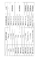
また、ROM111Bは、例えば、特図変動表示ゲームの実行時間、演出内容、リーチ状態の発生の有無などを規定する変動パターン(変動態様)を決定するための変動パターンテーブルを記憶している。変動パターンテーブルとは、始動記憶として記憶されている変動パターン乱数1〜3をCPU111Aが参照して変動パターンを決定するためのテーブルである。また、変動パターンテーブルには、結果がはずれとなる場合に選択されるはずれ変動パターンテーブル、結果が大当りとなる場合に選択される大当り変動パターンテーブル等が含まれる。さらに、これらのパターンテーブルには、後半変動パターンテーブル、前半変動パターンテーブルが含まれている。
In addition, the ROM 111B stores a variation pattern table for determining a variation pattern (variation mode) that defines, for example, the execution time of the special figure variation display game, the production contents, and the presence or absence of the reach state. The variation pattern table is a table for the
また、リーチ(リーチ状態)とは、表示状態が変化可能な表示装置を有し、該表示装置が時期を異ならせて複数の表示結果を導出表示し、該複数の表示結果が予め定められた特別結果態様となった場合に、遊技状態が遊技者にとって有利な遊技状態(特別遊技状態)となる遊技機10において、複数の表示結果の一部がまだ導出表示されていない段階で、既に導出表示されている表示結果が特別結果態様となる条件を満たしている表示状態をいう。また、別の表現をすれば、リーチ状態とは、表示装置の変動表示制御が進行して表示結果が導出表示される前段階にまで達した時点でも、特別結果態様となる表示条件からはずれていない表示態様をいう。そして、例えば、特別結果態様が揃った状態を維持しながら複数の変動表示領域による変動表示を行う状態(いわゆる全回転リーチ)もリーチ状態に含まれる。また、リーチ状態とは、表示装置の表示制御が進行して表示結果が導出表示される前段階にまで達した時点での表示状態であって、表示結果が導出表示される以前に決定されている複数の変動表示領域の表示結果の少なくとも一部が特別結果態様となる条件を満たしている場合の表示状態をいう。
Reach (reach state) has a display device whose display state can change, and the display device derives and displays a plurality of display results at different times, and the plurality of display results are predetermined. In the
よって、例えば、特図変動表示ゲームに対応して表示装置に表示される飾り特図変動表示ゲームが、表示装置における左、中、右の変動表示領域の各々で所定時間複数の識別情報を変動表示した後、左、右、中の順で変動表示を停止して結果態様を表示するものである場合、左、右の変動表示領域で、特別結果態様となる条件を満たした状態(例えば、同一の識別情報)で変動表示が停止した状態がリーチ状態となる。またこの他に、すべての変動表示領域の変動表示を一旦停止した時点で、左、中、右のうち何れか二つの変動表示領域で特別結果態様となる条件を満たした状態(例えば、同一の識別情報となった状態、ただし特別結果態様は除く)をリーチ状態とし、このリーチ状態から残りの一つの変動表示領域を変動表示するようにしても良い。そして、このリーチ状態には複数のリーチ演出が含まれ、特別結果態様が導出される可能性が異なる(信頼度が異なる)リーチ演出として、ノーマルリーチ(Nリーチ)、スペシャル1リーチ(SP1リーチ)、スペシャル2リーチ(SP2リーチ)、スペシャル3リーチ(SP3リーチ)、スペシャル4リーチ(SP4リーチ、プレミアリーチ)等が設定されている。なお、信頼度は、リーチなし<ノーマルリーチ<スペシャル1リーチ<スペシャル2リーチ<スペシャル3リーチ<スペシャル4リーチの順に高くなるようになっている。また、このリーチ状態は、少なくとも特図変動表示ゲームで特別結果態様が導出される場合(大当りとなる場合)における変動表示態様に含まれるようになっている。すなわち、特図変動表示ゲームで特別結果態様が導出されないと判定する場合(はずれとなる場合)における変動表示態様に含まれることもある。よって、リーチ状態が発生した状態は、リーチ状態が発生しない場合に比べて大当りとなる可能性の高い状態である。
Thus, for example, a decorative special figure fluctuation display game displayed on a display device corresponding to a special figure fluctuation display game fluctuates a plurality of identification information for a predetermined time in each of the left, middle, and right fluctuation display areas on the display device. After displaying, when the display of the result mode is stopped in the order of left, right, and middle, the condition that becomes the special result mode is satisfied in the left and right variable display areas (for example, The state in which the variable display is stopped with the same identification information) is the reach state. In addition to this, when the variable display of all the variable display areas is temporarily stopped, the condition that the special result mode is satisfied in any two of the left, middle, and right variable display areas (for example, the same The state in which the identification information is obtained (except for the special result mode) may be set as the reach state, and the remaining one variable display area may be variably displayed from the reach state. This reach state includes a plurality of reach effects, and the possibility of deriving a special result mode is different (reliability is different). As a reach effect, normal reach (N reach), special 1 reach (SP1 reach),
CPU111Aは、ROM111B内の遊技制御用プログラムを実行して、払出制御装置200や演出制御装置300に対する制御信号(コマンド)を生成したりソレノイドや表示装置の駆動信号を生成して出力して遊技機10全体の制御を行う。また、図示しないが、遊技用マイコン111は、特図変動表示ゲームの大当り判定用乱数や大当りの図柄を決定するための大当り図柄用乱数、特図変動表示ゲームでの変動パターン(各種リーチやリーチ無しの変動表示における変動表示ゲームの実行時間等を含む)を決定するための変動パターン乱数、普図変動表示ゲームの当り判定用乱数等を生成するための乱数生成回路と、発振回路113からの発振信号(原クロック信号)に基づいてCPU111Aに対する所定周期(例えば、4ミリ秒)のタイマ割込み信号や乱数生成回路の更新タイミングを与えるクロックを生成するクロックジェネレータを備えている。
The
また、CPU111Aは、後述する特図ゲーム処理における始動口スイッチ監視処理(ステップA1)や特図普段処理(ステップA9)にて、ROM111Bに記憶されている複数の変動パターンテーブルの中から、何れか一の変動パターンテーブルを取得する。具体的には、CPU111Aは、特図変動表示ゲームの遊技結果(大当り或いははずれ)や、現在の遊技状態としての特図変動表示ゲームの確率状態(通常確率状態或いは高確率状態)、現在の遊技状態としての普通変動入賞装置37の動作状態(通常動作状態或いは時短動作状態)、始動記憶数などに基づいて、複数の変動パターンテーブルの中から、何れか一の変動パターンテーブルを選択して取得する。また、遊技用マイコン111は、電源投入時や、大当り時などのイベント発生時、磁石や電波等による不正の検出時に個別IDレジスタ111Dに記憶されたIDを、情報伝達部71から出力する。
In addition, the
払出制御装置200は、図示しないが、CPU、ROM、RAM、入力インタフェース、出力インタフェース等を備え、遊技制御装置100からの賞球払出し指令(コマンドやデータ)に従って、払出ユニットの払出モータを駆動させ、賞球を払い出させるための制御を行う。また、払出制御装置200は、カードユニットからの貸球要求信号に基づいて払出ユニットの払出モータを駆動させ、貸球を払い出させるための制御を行う。また、払出制御装置200は、カードユニットと電気的に接続されていることを条件に発射装置を制御する発射制御装置201に遊技球の発射を許可する発射許可信号を出力する。
Although not shown, the
遊技用マイコン111の入力部120には、始動入賞口36内の始動口1スイッチ36a、普通変動入賞装置37内の始動口2スイッチ37a、普図始動ゲート34内のゲートスイッチ34a、一般入賞口スイッチ35a、カウントスイッチ38a,39aが近接I/F121を介して接続される。近接I/F121は、接続されるスイッチが近接スイッチである場合に、スイッチから供給されるハイレベルが11Vでロウレベルが7Vのような負論理の信号が入力され、0V−5Vの正論理の信号に変換するインタフェースチップである。近接I/F121は、入力の範囲が7V−11Vとされることで、近接スイッチのリード線が不正にショートされたり、スイッチがコネクタから外されたり、リード線が切断されてフローティングになったような異常な状態を検出することができ、異常検知信号を出力するように構成されている。
The
近接I/F121の出力はすべて第2入力ポート122へ供給されデータバス140を介して遊技用マイコン111に読み込まれるとともに、主基板100から中継基板70を介して図示しない試射試験装置へ供給されるようになっている。また、近接I/F121の出力のうち始動口1スイッチ36aと始動口2スイッチ37aの検出信号は、第2入力ポート122の他、反転回路112を介して遊技用マイコン111へ入力されるように構成されている。反転回路112を設けているのは、遊技用マイコン111の信号入力端子が、マイクロスイッチなどからの信号が入力されることを想定し、かつ負論理、すなわち、ロウレベル(0V)を有効レベルとして検知するように設計されているためである。
All the outputs of the proximity I /
従って、始動口1スイッチ36aと始動口2スイッチ37aとしてマイクロスイッチを使用する場合には、反転回路112を設けずに直接遊技用マイコン111へ検出信号を入力させるように構成することができる。つまり、始動口1スイッチ36aと始動口2スイッチ37aからの負論理の信号を直接遊技用マイコン111へ入力させたい場合には、近接スイッチを使用することはできない。上記のように近接I/F121は、信号のレベル変換機能を有する。このようなレベル変換機能を可能にするため、近接I/F121には、電源装置400から通常のICの動作に必要な例えば5Vのような電圧の他に、12Vの電圧が供給されるようになっている。
Therefore, when a micro switch is used as the
また、入力部120には、遊技機10の前面枠12等に設けられた不正検出用の磁気センサスイッチ61及び振動センサスイッチ62からの信号及び上記近接I/F121により変換された始動入賞口36内の始動口1スイッチ36a、普通変動入賞装置37内の始動口2スイッチ37a、ゲートスイッチ34a、一般入賞口スイッチ35a、カウントスイッチ38a,39aからの信号を取り込んでデータバス140を介して遊技用マイコン111に供給する第2入力ポート122が設けられている。第2入力ポート122が保持しているデータは、遊技用マイコン111が第2入力ポート122に割り当てられているアドレスをデコードすることによってイネーブル信号CE1をアサート(有効レベルに変化)することよって、読み出すことができる。後述の他のポートも同様である。
Further, the
さらに、入力部120には、遊技機10のガラス枠15等に設けられた前枠開放検出スイッチ63及び前面枠(遊技枠)12等に設けられた遊技枠開放検出スイッチ64からの信号及び払出制御装置200からの払出異常を示すステータス信号や払出し前の遊技球の不足を示すシュート球切れスイッチ信号、オーバーフローを示すオーバーフロースイッチ信号を取り込んでデータバス140を介して遊技用マイコン111に供給する第1入力ポート123が設けられている。オーバーフロースイッチ信号は、下皿23に遊技球が所定量以上貯留されていること(満杯になったこと)を検出したときに出力される信号である。
Further, the
また、入力部120には、電源装置400からの停電監視信号や初期化スイッチ信号、リセット信号などの信号を遊技用マイコン111等に入力するためのシュミットトリガ回路124が設けられており、シュミットトリガ回路124はこれらの入力信号からノイズを除去する機能を有する。電源装置400からの信号のうち停電監視信号と初期化スイッチ信号は、一旦第1入力ポート123に入力され、データバス140を介して遊技用マイコン111に取り込まれる。つまり、前述の各種スイッチからの信号と同等の信号として扱われる。遊技用マイコン111に設けられている外部からの信号を受ける端子の数には制約があるためである。
Further, the
一方、シュミットトリガ回路124によりノイズ除去されたリセット信号RSTは、遊技用マイコン111に設けられているリセット端子に直接入力されるとともに、出力部130の各ポートに供給される。また、リセット信号RSTは出力部130を介さずに直接中継基板70に出力することで、試射試験装置へ出力するために中継基板70のポート(図示省略)に保持される試射試験信号をオフするように構成されている。また、リセット信号RSTを中継基板70を介して試射試験装置へ出力可能に構成するようにしてもよい。なお、リセット信号RSTは入力部120の各ポート122,123には供給されない。リセット信号RSTが入る直前に遊技用マイコン111によって出力部130の各ポートに設定されたデータはシステムの誤動作を防止するためリセットする必要があるが、リセット信号RSTが入る直前に入力部120の各ポートから遊技用マイコン111が読み込んだデータは、遊技用マイコン111のリセットによって廃棄されるためである。
On the other hand, the reset signal RST from which noise has been removed by the
出力部130は、データバス140に接続され払出制御装置200へ出力する4ビットのデータ信号とデータの有効/無効を示す制御信号(データストローブ信号)及び演出制御装置300へ出力するデータストローブ信号SSTBを生成する第1出力ポート131と、演出制御装置300へ出力する8ビットのデータ信号を生成する第2出力ポート132とを備える。遊技制御装置100から払出制御装置200及び演出制御装置300へは、パラレル通信でデータが送信される。また、出力部130には、演出制御装置300の側から遊技制御装置100へ信号を入力できないようにするため、すなわち、片方向通信を担保するために第1出力ポート131からの上記データストローブ信号SSTB及び第2出力ポート132からの8ビットのデータ信号を出力する単方向のバッファ133が設けられている。なお、第1出力ポート131から払出制御装置200へ出力する信号に対してもバッファを設けるようにしてもよい。
The
さらに、出力部130には、データバス140に接続され図示しない認定機関の試射試験装置へ変動表示ゲームの特図図柄情報を知らせるデータや大当りの確率状態を示す信号などを中継基板70を介して出力するバッファ134が実装可能に構成されている。このバッファ134は遊技店に設置される実機(量産販売品)としてのパチンコ遊技機の遊技制御装置(主基板)には実装されない部品である。なお、前記近接I/F121から出力される始動口スイッチなど加工の必要のないスイッチの検出信号は、バッファ134を通さずに中継基板70を介して試射試験装置へ供給される。
In addition, the
一方、磁気センサスイッチ61や振動センサスイッチ62のようにそのままでは試射試験装置へ供給できない検出信号は、一旦遊技用マイコン111に取り込まれて他の信号若しくは情報に加工されて、例えば遊技機が遊技制御できない状態であることを示すエラー信号としてデータバス140からバッファ134、中継基板70を介して試射試験装置へ供給される。なお、中継基板70には、上記バッファ134から出力された信号を取り込んで試射試験装置へ供給するポートや、バッファを介さないスイッチの検出信号の信号線を中継して伝達するコネクタなどが設けられている。中継基板70上のポートには、遊技用マイコン111から出力されるチップイネーブル信号CEも供給され、該信号CEにより選択制御されたポートの信号が試射試験装置へ供給されるようになっている。
On the other hand, detection signals such as the
また、出力部130には、データバス140に接続され第1特別変動入賞装置38を開成させるソレノイド(大入賞口ソレノイド)38bや第2特別変動入賞装置39を開成させるソレノイド(大入賞口ソレノイド)39b、普通変動入賞装置37の可動部材37bを開成させるソレノイド(普電ソレノイド)37cの開閉データと、一括表示装置50のLEDのカソード端子が接続されているデジット線のオン/オフデータを出力するための第3出力ポート135、一括表示装置50に表示する内容に応じてLEDのアノード端子が接続されているセグメント線のオン/オフデータを出力するための第4出力ポート136、大当り情報など遊技機10に関する情報を情報伝達部(外部情報端子板)71へ出力するための第5出力ポート137が設けられている。情報伝達部(外部情報端子板)71から出力された遊技機10に関する情報は、例えば遊技店に設置された情報収集端末や遊技場内部管理装置(図示省略)に供給される。
In addition, the
さらに、出力部130には、第3出力ポート135から出力される大入賞口ソレノイド38bの開閉データ信号を受けてソレノイド駆動信号や普電ソレノイド37cの開閉データ信号を受けてソレノイド駆動信号を生成し出力する第1ドライバ(駆動回路)138a、第3出力ポート135から出力される一括表示装置50の電流引き込み側のデジット線のオン/オフ駆動信号を出力する第2ドライバ138b、第4出力ポート136から出力される一括表示装置50の電流供給側のセグメント線のオン/オフ駆動信号を出力する第3ドライバ138c、第5出力ポート137から管理装置等の外部装置へ供給する外部情報信号を情報伝達部(外部情報端子板)71へ出力する第4ドライバ138dが設けられている。
Further, the
上記第1ドライバ138aには、32Vで動作するソレノイドを駆動できるようにするため、電源電圧としてDC32Vが電源装置400から供給される。また、一括表示装置50のセグメント線を駆動する第3ドライバ138cには、DC12Vが供給される。デジット線を駆動する第2ドライバ138bは、表示データに応じたデジット線を電流で引き抜くためのものであるため、電源電圧は12V又は5Vのいずれであってもよい。12Vを出力する第3ドライバ138cによりセグメント線を介してLEDのアノード端子に電流を流し込み、接地電位を出力する第2ドライバ138bによりカソード端子よりセグメント線を介して電流を引き抜くことで、ダイナミック駆動方式で順次選択されたLEDに電源電圧が流れて点灯される。外部情報信号を情報伝達部(外部情報端子板)71へ出力する第4ドライバ138dは、外部情報信号に12Vのレベルを与えるため、DC12Vが供給される。なお、バッファ134や第3出力ポート135、第1ドライバ138a等は、遊技制御装置100の出力部130、すなわち、主基板ではなく、中継基板70側に設けるようにしてもよい。
The first driver 138a is supplied with DC32V from the
さらに、出力部130には、外部の検査装置1000へ各遊技機の識別コードやプログラムなどの情報を送信するためのフォトカプラ139が設けられている。フォトカプラ139は、遊技用マイコン111が検査装置1000との間でシリアル通信によってデータの送受信を行えるように双方通信可能に構成されている。なお、かかるデータの送受信は、通常の汎用マイクロプロセッサと同様に遊技用マイコン111が有するシリアル通信端子を利用して行われるため、入力ポート122,123のようなポートは設けられていない。
Further, the
次に、図11を用いて、演出制御装置300の構成について説明する。
演出制御装置300は、遊技用マイコン111と同様にアミューズメントチップ(IC)からなる主制御用マイコン(1stCPU)311と、該1stCPU311の制御下でもっぱら映像制御を行う映像制御用マイコン(2ndCPU)312と、該2ndCPU312からのコマンドやデータに従って表示装置41への映像表示のための画像処理を行うグラフィックプロセッサとしてのVDP(Video Display Processor)313と、各種のメロディや効果音などをスピーカ(音声出力部)19a,19bから再生させるため音の出力を制御する音源LSI314を備えている。
Next, the configuration of the
The
上記主制御用マイコン(1stCPU)311と映像制御用マイコン(2ndCPU)312には、各CPUが実行するプログラムを格納したPROM(プログラマブルリードオンリメモリ)からなるプログラムROM321、322がそれぞれ接続され、VDP313にはキャラクタ画像や映像データが記憶された画像ROM323が接続され、音源LSI314には音声データが記憶された音声ROM324が接続されている。主制御用マイコン(1stCPU)311は、遊技用マイコン111からのコマンドを解析し、演出内容を決定して映像制御用マイコン312へ出力映像の内容を指示したり、音源LSI314への再生音の指示、装飾ランプの点灯、モータの駆動制御、演出時間の管理などの処理を実行する。主制御用マイコン(1stCPU)311と映像制御用マイコン(2ndCPU)312の作業領域を提供するRAMは、それぞれのチップ内部に設けられている。なお、作業領域を提供するRAMはチップの外部に設けるようにしてもよい。
The main control microcomputer (1st CPU) 311 and the video control microcomputer (2nd CPU) 312 are connected to program
特に限定されるわけではないが、主制御用マイコン(1stCPU)311と映像制御用マイコン(2ndCPU)312との間、主制御用マイコン(1stCPU)311と音源LSI314との間は、それぞれシリアル方式でデータの送受信が行われ、映像制御用マイコン(2ndCPU)312との間、主制御用マイコン(1stCPU)311とVDP313との間は、パラレル方式でデータの送受信が行われるように構成されている。パラレル方式でデータを送受信することで、シリアルの場合よりも短時間にコマンドやデータを送信することができる。VDP313には、画像ROM323から読み出されたキャラクタなどの画像データを展開したり加工したりするのに使用される超高速なVRAM(ビデオRAM)313aや、画像を拡大、縮小処理するためのスケーラ313b、LVDS(小振幅信号伝送)方式で表示装置41へ送信する映像信号を生成する信号変換回路313cなどが設けられている。
Although not particularly limited, a serial system is used between the main control microcomputer (1st CPU) 311 and the video control microcomputer (2nd CPU) 312 and between the main control microcomputer (1st CPU) 311 and the
VDP313から主制御用マイコン311へは表示装置41の映像と前面枠12や遊技盤30に設けられている装飾ランプの点灯を同期させるために垂直同期信号VSYNCが入力される。さらに、VDP313から映像制御用マイコン312へは、VRAMへの描画の終了等処理状況を知らせるため割込み信号INT0〜n及び映像制御用マイコン312からのコマンドやデータの受信待ちの状態にあることを知らせるためのウェイト信号WAITが入力される。また、映像制御用マイコン312から主制御用マイコン311へは、映像制御用マイコン312が正常に動作していることを知らせるとともにコマンドの送信タイミングを与える同期信号SYNCが入力される。主制御用マイコン311と音源LSI314との間は、ハンドシェイク方式でコマンドやデータの送受信を行うために、呼び掛け(コール)信号CTSと応答(レスポンス)信号RTSが交換される。
A vertical synchronization signal VSYNC is input from the
なお、映像制御用マイコン(2ndCPU)312には、主制御用マイコン(1stCPU)311よりも高速なつまり高価なCPUが使用されている。主制御用マイコン(1stCPU)311とは別に映像制御用マイコン(2ndCPU)312を設けて処理を分担させることによって、主制御用マイコン(1stCPU)311のみでは実現困難な大画面で動きの速い映像を表示装置41に表示させることが可能となるとともに、映像制御用マイコン(2ndCPU)312と同等な処理能力を有するCPUを2個使用する場合に比べてコストの上昇を抑制することができる。また、CPUを2つ設けることによって、2つのCPUの制御プログラムを別々に並行して開発することが可能となり、これによって新機種の開発期間を短縮することができる。
Note that the video control microcomputer (2ndCPU) 312 uses a CPU that is faster or more expensive than the main control microcomputer (1stCPU) 311. By providing a video control microcomputer (2ndCPU) 312 separately from the main control microcomputer (1stCPU) 311 and sharing the processing, it is possible to display a fast moving image on a large screen that is difficult to achieve with the main control microcomputer (1stCPU) 311 alone. It is possible to display on the
また、演出制御装置300には、遊技制御装置100から送信されてくるコマンドを受信するインタフェースチップ(コマンドI/F)331が設けられている。このコマンドI/F331を介して、遊技制御装置100から演出制御装置300へ送信された変動開始コマンド、始動口入賞演出コマンド、始動口入賞演出図柄コマンド、客待ちデモコマンド、ファンファーレコマンド、確率情報コマンド、変動停止コマンド、大当り終了コマンド、エラー指定コマンド等を、演出制御指令信号として受信する。遊技制御装置100の遊技用マイコン111はDC5Vで動作し、演出制御装置300の主制御用マイコン(1stCPU)311はDC3.3Vで動作するため、コマンドI/F331には信号のレベル変換の機能が設けられている。
In addition, the
また、演出制御装置300には、遊技盤30(包囲枠体40を含む)に設けられているLEDを有する盤装飾装置46(左上発光装置621、左下発光装置622、右上発光装置623及び右下発光装置624の装飾LED643を含む)や、左上発光装置621、左下発光装置622、右上発光装置623及び右下発光装置624に設けられた特図1第4図柄LED644、特図2第4図柄LED645により構成される変化表示部673を駆動制御する盤装飾LED制御回路332が設けられている。また、前面枠12に設けられているLED(発光ダイオード)を有する枠装飾装置18を駆動制御する枠装飾LED制御回路333、遊技盤30(包囲枠体40を含む)に設けられている盤演出装置44(例えば表示装置41における演出表示と協働して演出効果を高める可動役物等)を駆動制御する盤演出モータ/SOL制御回路334、前面枠12に設けられている枠演出装置45(例えば前記ムービングライト16を動作させるモータ等)を駆動制御する枠演出モータ制御回路335が設けられている。なお、ランプやモータ及びソレノイドなどを駆動制御するこれらの制御回路332〜335は、アドレス/データバス340を介して主制御用マイコン(1stCPU)311と接続されている。
The
さらに、演出制御装置300には、前面枠12に設けられた演出ボタン25に内蔵されているスイッチ25aや上記盤演出装置44内のモータの初期位置を検出する演出モータスイッチのオン/オフ状態を検出して主制御用マイコン(1stCPU)311へ検出信号を入力するスイッチ入力回路336、前面枠12に設けられた上スピーカ19aを駆動するオーディオパワーアンプなどからなるアンプ回路337a、前面枠12に設けられた下スピーカ19bを駆動するアンプ回路337bが設けられている。
Further, the
電源装置400の通常電源部410は、上記のような構成を有する演出制御装置300やそれによって制御される電子部品に対して所望のレベルの直流電圧を供給するため、モータやソレノイドを駆動するためのDC32V、液晶パネル等からなる表示装置41を駆動するためのDC12V、コマンドI/F331の電源電圧となるDC5Vの他に、LEDやスピーカを駆動するためのDC18Vやこれらの直流電圧の基準としたり電源モニタランプを点灯させるのに使用するNDC24Vの電圧を生成するように構成されている。さらに、主制御用マイコン(1stCPU)311や映像制御用マイコン(2ndCPU)312として、3.3Vあるいは1.2Vのような低電圧で動作するLSIを使用する場合には、DC5Vに基づいてDC3.3VやDC1.2Vを生成するためのDC−DCコンバータが演出制御装置300に設けられる。なお、DC−DCコンバータは通常電源部410に設けるようにしてもよい。
The normal
電源装置400の制御信号生成部430により生成されたリセット信号RSTは、主制御用マイコン311、映像制御用マイコン312、VDP313、音源LSI314、ランプやモータなどを駆動制御する制御回路332〜335、スピーカを駆動するアンプ回路337a,337bに供給され、これらをリセット状態にする。また、この実施形態においては、映像制御用マイコン312の有する汎用のポートを利用して、VDP313に対するリセット信号を生成して供給する機能を有するように構成されている。これにより、映像制御用マイコン312とVDP313の動作の連携性を向上させることができる。
The reset signal RST generated by the control
次に、これらの制御回路において行われる遊技制御について説明する。
遊技制御装置100の遊技用マイコン111のCPU111Aでは、普図始動ゲート34に備えられたゲートスイッチ34aからの遊技球の検出信号の入力に基づき、普図の当り判定用乱数値を抽出してROM111Bに記憶されている判定値と比較し、普図変動表示ゲームの当りはずれを判定する処理を行う。そして、普図表示器に、識別情報を所定時間変動表示した後、停止表示する普図変動表示ゲームを表示する処理を行う。この普図変動表示ゲームの結果が当りの場合は、普図表示器に特別の結果態様を表示するとともに、普電ソレノイド37cを動作させ、普通変動入賞装置37の可動部材37b,37bを所定時間(例えば、0.3秒間)前述のように開放する制御を行う。なお、普図変動表示ゲームの結果がはずれの場合は、普図表示器にはずれの結果態様を表示する制御を行う。
Next, game control performed in these control circuits will be described.
The
また、始動入賞口36に備えられた始動口1スイッチ36aからの遊技球の検出信号の入力に基づき始動入賞(始動記憶)を記憶し、この始動記憶に基づき、第1特図変動表示ゲームの大当り判定用乱数値を抽出してROM111Bに記憶されている判定値と比較し、第1特図変動表示ゲームの当りはずれを判定する処理を行う。また、普通変動入賞装置37に備えられた始動口2スイッチ37aからの遊技球の検出信号の入力に基づき始動記憶を記憶し、この始動記憶に基づき、第2特図変動表示ゲームの大当り判定用乱数値を抽出してROM111Bに記憶されている判定値と比較し、第2特図変動表示ゲームの当りはずれを判定する処理を行う。
Further, a start winning (starting memory) is stored based on an input of a detection signal of a game ball from a starting
そして、遊技制御装置100のCPU111Aは、上記の第1特図変動表示ゲームや第2特図変動表示ゲームの判定結果を含む制御信号(演出制御コマンド)を、演出制御装置300に出力する。そして、特図1表示器や特図2表示器に、識別情報を所定時間変動表示した後、停止表示する特図変動表示ゲームを表示する処理を行う。また、演出制御装置300では、遊技制御装置100からの制御信号に基づき、表示装置41と左上発光装置621、左下発光装置622、右上発光装置623及び右下発光装置624の変化表示部673で特図変動表示ゲームに対応した飾り特図変動表示ゲームを表示する処理を行う。さらに、演出制御装置300では、遊技制御装置100からの制御信号に基づき、演出状態(演出モード)の設定や、スピーカ19a,19bからの音の出力、各種LEDの発光を制御する処理等を行う。
Then, the
そして、遊技制御装置100のCPU111Aは、特図変動表示ゲームの結果が当りの場合は、特図1表示器や特図2表示器に特別結果態様を表示するとともに、特別遊技状態を発生させる処理を行う。特別遊技状態を発生させる処理においては、CPU111Aは、例えば、大入賞口ソレノイド38bにより第1特別変動入賞装置38の開閉扉38c又は大入賞口ソレノイド39bにより第2特別変動入賞装置39の開閉部材39cを開放させ、大入賞口内への遊技球の流入を可能とする制御を行う。そして、大入賞口に所定個数(例えば、10個)の遊技球が入賞するか、大入賞口の開放から所定の開放可能時間が経過するかの何れかの条件が達成されるまで大入賞口を開放することを1ラウンドとし、これを所定ラウンド回数(例えば、15回や2回)継続する(繰り返す)制御(サイクル遊技)を行う。また、特図変動表示ゲームの結果がはずれの場合は、特図1表示器や特図2表示器にはずれの結果態様を表示する制御を行う。
Then, when the result of the special figure variation display game is a win, the
また、遊技制御装置100は、特図変動表示ゲームの結果態様に基づき、特別遊技状態の終了後に、遊技状態として高確率状態を発生可能となっている。この高確率状態は、特図変動表示ゲームにて当り結果となる確率が、通常確率状態に比べて高い状態である。また、第1特図変動表示ゲーム及び第2特図変動表示ゲームのどちらの特図変動表示ゲームの結果態様に基づき高確率状態となっても、第1特図変動表示ゲーム及び第2特図変動表示ゲームの両方が高確率状態となる。
In addition, the
また、遊技制御装置100は、特図変動表示ゲームの結果態様に基づき、特別遊技状態の終了後に、遊技状態として時短状態(普図高確率状態)を発生可能となっている。この時短状態においては、普図変動表示ゲーム及び普通変動入賞装置37を時短動作状態とする制御を行い、普通変動入賞装置37が通常動作状態である場合よりも、単位時間あたりの普通変動入賞装置37の開放時間が実質的に多くなるように制御するようになっている。
In addition, the
例えば、時短状態においては、前述の普図変動表示ゲームの実行時間(普図変動時間)を第1変動表示時間よりも短い第2変動表示時間となるように制御することが可能である(例えば、10000ミリ秒が600ミリ秒)。また、時短状態においては、普図変動表示ゲームの結果を表示する普図停止時間を第1停止時間よりも短い第2停止時間となるように制御することが可能である(例えば、1604ミリ秒が704ミリ秒)。また、時短状態においては、普図変動表示ゲームが当り結果となって普通変動入賞装置37が開放される場合に、開放時間(普電開放時間)を通常状態(普図低確率状態)の第1開放時間よりも長い第2開放時間となるように制御することが可能である(例えば、300ミリ秒が800ミリ秒)。また、時短状態においては、普図変動表示ゲームの1回の当り結果に対して、普通変動入賞装置37の開放回数(普電開放回数)を1回の第1開放回数ではなく、2回以上の複数回(例えば、4回)の第2開放回数に設定することが可能である。また、時短状態においては、普図変動表示ゲームの当り結果となる確率(普図確率)を通常動作状態である場合の通常確率(普図低確率状態)よりも高い高確率(普図高確率状態)とすることが可能である。
For example, in the short-time state, it is possible to control the execution time of the above-described normal map change display game (the normal map change time) to be the second change display time shorter than the first change display time (for example, 10,000 milliseconds is 600 milliseconds). Further, in the short time state, it is possible to control the general map stop time for displaying the result of the normal map change display game to be the second stop time shorter than the first stop time (for example, 1604 milliseconds). Is 704 milliseconds). Also, in the short-time state, when the normal
時短状態においては、普図変動時間、普図停止時間、普電開放回数、普電開放時間、普図確率の何れか一つ又は複数を変化させることで普通変動入賞装置37を開状態に状態変換する時間を通常よりも延長するようにする。また、高確率状態と時短状態は、それぞれ独立して発生可能であり、両方を同時に発生することも可能であるし一方のみを発生させることも可能である。なお、以下の説明や図中では、時短状態を特定遊技状態や普電サポート状態又は電サポ状態と称することがある。
In the short-time state, the normal
次に、遊技機10の制御について説明する。まず、遊技制御装置100の遊技用マイクロコンピュータ(遊技用マイコン)111によって実行される制御について説明する。遊技用マイコン111による制御処理は、主に、図12及び図13に示すメイン処理と、所定時間周期(例えば、4ミリ秒)で行われる図14に示すタイマ割込み処理とからなる。
Next, control of the
〔メイン処理〕
まず、メイン処理について説明する。メイン処理は、遊技機10の電源が投入されることで開始される。このメイン処理においては、図12に示すように、まず、割込みを禁止する処理(ステップS1)を行ってから、割込みが発生したときに実行するジャンプ先のベクタアドレスを設定する割込みベクタ設定処理(ステップS2)、割込みが発生したときにレジスタ等の値を退避する領域の先頭アドレスであるスタックポインタを設定するスタックポインタ設定処理(ステップS3)、割込み処理のモードを設定する割込みモード設定処理(ステップS4)を行う。
[Main processing]
First, the main process will be described. The main process is started when the
次いで、払出制御装置(払出基板)200のプログラムが正常に起動するのを待つため、例えば4ミリ秒の時間待ちを行う(ステップS5)。これにより、遊技機10の電源投入の際に仮に遊技制御装置100が先に立ち上がって払出制御装置200が立ち上がる前にコマンドを払出制御装置200へ送ってしまい、払出制御装置200がコマンドを取りこぼすのを回避することができる。次いで、RAMやEEPROM等の読出し書込み可能なRWM(リードライトメモリ)のアクセス許可をし、全出力ポートに出力が無い状態に設定するOFFデータを出力する(ステップS6,S7)。次いで、シリアルポート(遊技用マイコン111に予め搭載されているポートで、本実施形態では、払出制御装置200や演出制御装置300とパラレル通信を行っているため使用しない)を使用しない状態に設定する処理を行う(ステップS8)。
Next, in order to wait for the program of the payout control apparatus (payout board) 200 to start normally, for example, a time of 4 milliseconds is waited (step S5). As a result, when the
次いで、電源装置400内の初期化スイッチがONしているか否かを判定する(ステップS9)。ステップS9で、初期化スイッチがOFFと判定した場合(ステップS9;No)には、RWM内の停電検査領域1の値が正常な停電検査領域チェックデータ1であるかをチェックし(ステップS10)、停電検査領域1の値が正常であるか否かを判定する(ステップS11)。ステップS11で、停電検査領域1の値が正常であると判定した場合(ステップS11;Yes)には、RWM内の停電検査領域2の値が正常な停電検査領域チェックデータ2であるかをチェックし(ステップS12)、停電検査領域2の値が正常であるか否かを判定する(ステップS13)。
Next, it is determined whether or not the initialization switch in the
ステップS13で、停電検査領域2の値が正常であると判定した場合(ステップS13;Yes)には、RWM内の所定領域のチェックサムを算出し(ステップS14)、算出したチェックサムと電源断時のチェックサムとを比較して(ステップS15)、チェックサムが一致するか否かを判定する(ステップS16)。ステップS16で、チェックサムが一致すると判定した場合(ステップS16;Yes)には、図13のステップS17へ移行し、停電から正常に復旧した場合の処理を行う。
If it is determined in step S13 that the value of the power
また、ステップS9で初期化スイッチがONと判定した場合(ステップS9;Yes)や、ステップS11又はステップS13で停電検査領域の値が正常でないと判定した場合(ステップS11;No又はステップS13;No)、ステップS16でチェックサムが一致しないと判定した場合(ステップS16;No)には、図13のステップS24へ移行して、初期化の処理を行う。 Moreover, when it determines with the initialization switch being ON at step S9 (step S9; Yes), or when it determines with the value of a power failure inspection area | region not being normal at step S11 or step S13 (step S11; No or step S13; No) ) If it is determined in step S16 that the checksums do not match (step S16; No), the process proceeds to step S24 in FIG. 13 to perform initialization processing.
図13のステップS17では全ての停電検査領域をクリアし、チェックサム領域をクリアして(ステップS18)、エラーや不正監視に係る領域をリセットする(ステップS19)。次いで、RWM内の遊技状態を記憶する領域を調べて遊技状態が高確率状態であるか否かを判定する(ステップS20)。ステップS20で、高確率状態でないと判定した場合(ステップS20;No)には、ステップS21,S22をスキップしてステップS23へ移行する。 In step S17 of FIG. 13, all the power outage inspection areas are cleared, the checksum area is cleared (step S18), and the area related to error and fraud monitoring is reset (step S19). Next, an area for storing the gaming state in the RWM is examined to determine whether or not the gaming state is a high probability state (step S20). If it is determined in step S20 that the state is not a high probability state (step S20; No), steps S21 and S22 are skipped and the process proceeds to step S23.
一方、ステップS20で、高確率状態であると判定した場合(ステップS20;Yes)には、高確率報知フラグ領域にON情報をセーブし(ステップS21)、例えば一括表示装置50に設けられる高確率報知LED(確率状態表示部)をON(点灯)させるONデータをセグメント領域にセーブする(ステップS22)。次いで、後述の特図ゲーム処理を合理的に実行するために用意されている特図ゲーム処理番号に対応する停電復旧時のコマンドを演出制御装置300へ送信する処理(ステップS23)を行ってステップS29へ進む。
On the other hand, when it is determined in step S20 that the state is a high probability state (step S20; Yes), ON information is saved in the high probability notification flag area (step S21), and the high probability provided in the
一方、ステップS9、S11、S13、S16からステップS24へジャンプした場合には、アクセス禁止領域より前の全作業領域をクリアし(ステップS24)、アクセス禁止領域より後の全スタック領域をクリアして(ステップS25)、初期化すべき領域に電源投入時の初期値をセーブする(ステップS26)。次いで、RWMクリアに関する外部情報を出力する期間の時間値を設定し(ステップS27)、電源投入時のコマンドを演出制御装置300へ送信して(ステップS28)、ステップS29へ進む。 On the other hand, when jumping from step S9, S11, S13, S16 to step S24, all work areas before the access prohibited area are cleared (step S24), and all stack areas after the access prohibited area are cleared. (Step S25), the initial value at power-on is saved in the area to be initialized (Step S26). Next, a time value for outputting the external information related to RWM clear is set (step S27), a command for turning on the power is transmitted to the effect control device 300 (step S28), and the process proceeds to step S29.
ステップS29では、個別IDレジスタ111Dから個体識別情報を取得してシリアル通信回路にセットし、情報伝達部71から出力する処理を行う。次いで、遊技用マイコン111(クロックジェネレータ)内のタイマ割込み信号及び乱数更新トリガ信号(CTC)を発生するCTC(Counter/Timer Circuit)回路を起動する処理を行う(ステップS30)。なお、CTC回路は、遊技用マイコン111内のクロックジェネレータに設けられている。クロックジェネレータは、水晶発振器113からの発振信号(原クロック信号)を分周する分周回路と、分周された信号に基づいてCPU111Aに対して所定周期(例えば、4ミリ秒)のタイマ割込み信号及び乱数生成回路へ供給する乱数更新のトリガを与える信号CTCを発生するCTC回路とを備えている。
In step S29, the individual identification information is obtained from the
上記ステップS30のCTC起動処理の後は、乱数生成回路を起動設定する処理を行う(ステップS31)。具体的には、乱数生成回路内の所定のレジスタ(CTC更新許可レジスタ)へ乱数生成回路を起動させるためのコード(指定値)の設定などがCPU111Aによって行われる。次いで、電源投入時の乱数生成回路内の所定のレジスタ(ソフト乱数レジスタ1〜n)の値を抽出し、対応する各種初期値乱数(大当り図柄を決定する乱数(大当り図柄乱数1、大当り図柄乱数2)、普図の当りを決定する乱数(当り乱数))の初期値(スタート値)としてRWMの所定領域にセーブしてから(ステップS32)、割込みを許可する(ステップS33)。本実施形態で使用するCPU111A内の乱数生成回路においては、電源投入毎にソフト乱数レジスタの初期値が変わるように構成されているため、この値を各種初期値乱数の初期値(スタート値)とすることで、ソフトウェアで生成される乱数の規則性を崩すことができ、遊技者による不正な乱数の取得を困難にすることができる。
After the CTC activation process in step S30, a process for setting the activation of the random number generation circuit is performed (step S31). Specifically, the
次いで、各種初期値乱数の値を更新して乱数の規則性を崩すための初期値乱数更新処理(ステップS34)を行う。なお、本実施形態においては、特に限定されるわけではないが、大当り乱数は乱数生成回路において生成される乱数(大当り乱数)を使用して生成するように構成されている。つまり、大当り乱数はハードウェアで生成されるハード乱数であり、大当り図柄乱数、当り乱数はソフトウェアで生成されるソフト乱数である。 Next, initial value random number update processing (step S34) is performed to update the values of various initial value random numbers to break the regularity of the random numbers. In the present embodiment, although not particularly limited, the big hit random number is configured to be generated using a random number (big hit random number) generated in a random number generation circuit. That is, the big hit random number is a hard random number generated by hardware, and the big hit symbol random number is a soft random number generated by software.
上記ステップS34の初期値乱数更新処理の後、電源装置400から入力されている停電監視信号をポート及びデータバスを介して読み込んでチェックする回数を設定し(ステップS35)、停電監視信号がONであるか否かの判定を行う(ステップS36)。ステップS36で、停電監視信号がONでないと判定した場合(ステップS36;No)には、初期値乱数更新処理(ステップS34)に戻る。すなわち、停電が発生していない場合には、初期値乱数更新処理と停電監視信号のチェック(ループ処理)を繰り返し行う。初期値乱数更新処理(ステップS34)の前に割り込みを許可する(ステップS33)ことによって、初期値乱数更新処理中にタイマ割込みが発生すると割込み処理が優先して実行されるようになり、タイマ割込みが初期値乱数更新処理によって待たされることで割込み処理が圧迫されるのを回避することができる。
After the initial value random number update process in step S34, the number of times the power failure monitoring signal input from the
なお、上記ステップS34での初期値乱数更新処理は、メイン処理のほか、タイマ割込み処理の中においても初期値乱数更新処理を行う方法もあり、そのような方法を採用した場合には両方で初期値乱数更新処理が実行されるのを回避するため、メイン処理で初期値乱数更新処理を行う場合には割込みを禁止してから更新して割込みを解除する必要があるが、本実施形態のようにタイマ割込み処理の中での初期値乱数更新処理はせず、メイン処理内のみにした場合には初期値乱数更新処理の前に割込みを解除しても何ら問題はなく、それによってメイン処理が簡素化されるという利点がある。 Note that the initial value random number update process in step S34 includes a method of performing the initial value random number update process in the timer interrupt process in addition to the main process. In order to avoid execution of the value random number update process, when performing the initial value random number update process in the main process, it is necessary to disable the interrupt and then update to cancel the interrupt. If the initial value random number update process in the timer interrupt process is not performed in the main process and only the main process is performed, there is no problem even if the interrupt is canceled before the initial value random number update process. There is an advantage that it is simplified.
また、ステップS36で、停電監視信号がONであると判定した場合(ステップS36;Yes)には、ステップS35で設定したチェック回数の分だけ停電監視信号のON状態が継続しているか否かを判定する(ステップS37)。ステップS37で、継続していないと判定した場合(ステップS37;No)には、停電監視信号がONであるかの判定(ステップS36)に戻る。一方、ステップS37で、継続していると判定した場合(ステップS37;Yes)、すなわち、停電が発生していると判定した場合には、一旦割込みを禁止する処理(ステップS38)、全出力ポートにOFFデータを出力する処理(ステップS39)を行う。 If it is determined in step S36 that the power failure monitoring signal is ON (step S36; Yes), it is determined whether or not the power failure monitoring signal is on for the number of checks set in step S35. Determination is made (step S37). If it is determined in step S37 that it is not continued (step S37; No), the process returns to the determination of whether the power failure monitoring signal is ON (step S36). On the other hand, if it is determined in step S37 that it is continuing (step S37; Yes), that is, if it is determined that a power failure has occurred, processing for temporarily prohibiting interruption (step S38), all output ports The process of outputting OFF data to (step S39).
次いで、停電検査領域1に停電検査領域チェックデータ1をセーブし(ステップS40)、停電検査領域2に停電検査領域チェックデータ2をセーブする(ステップS41)。次いで、RWMの電源遮断時のチェックサムを算出する処理(ステップS42)、算出したチェックサムをチェックサム領域にセーブする処理(ステップS43)、RWMへのアクセスを禁止する処理(ステップS44)を行ってから、遊技機10の電源が遮断されるのを待つ。このように、停電検査領域にチェックデータをセーブするとともに、電源遮断時のチェックサムを算出することで、停電等に伴う遊技機10の電源遮断の前にRWMに記憶されていた情報が正しくバックアップされているか否かを、遊技機10の電源再投入時に判断することができる。
Next, the power failure inspection
〔タイマ割込み処理〕
次に、タイマ割込み処理について説明する。タイマ割込み処理は、クロックジェネレータ内のCTC回路で生成される周期的なタイマ割込み信号がCPU111Aに入力されることで開始される。CPU111Aにおいてタイマ割込みが発生すると、図14のタイマ割込み処理が開始される。
[Timer interrupt processing]
Next, timer interrupt processing will be described. The timer interrupt process is started when a periodic timer interrupt signal generated by the CTC circuit in the clock generator is input to the
タイマ割込み処理が開始されると、遊技制御装置100の遊技用マイコン111は、まず所定のレジスタに保持されている値をRWMに移すレジスタ退避の処理(ステップS51)を行う。なお、本実施形態において遊技用マイコンとして使用しているZ80系のマイコンでは、当該処理を表レジスタに保持されている値を裏レジスタに退避することで置き換えることができる。次いで、各種センサ(始動口1スイッチ36a、始動口2スイッチ37a、普図のゲートスイッチ34a、一般入賞口スイッチ35a、カウントスイッチ38a,39aなど)からの入力の取込み、すなわち、各入力ポートの状態を読み込む入力処理(ステップS52)を行う。次いで、各種処理でセットされた出力データに基づき、ソレノイド(大入賞口SOL38b,39b、普電SOL37c)等のアクチュエータの駆動制御などを行うための出力処理(ステップS53)を行う。
When the timer interrupt process is started, the
次いで、各種処理で送信バッファにセットされたコマンドを演出制御装置300や払出制御装置200等に出力するコマンド送信処理(ステップS54)、乱数更新処理1(ステップS55)、乱数更新処理2(ステップS56)を行う。次いで、始動口1スイッチ36a、始動口2スイッチ37a、普図のゲートスイッチ34a、一般入賞口スイッチ35a、カウントスイッチ38a,39aから正常な信号の入力があるか否かの監視や、エラーの監視(前面枠やガラス枠が開放されていないかなど)を行う入賞口スイッチ/エラー監視処理(ステップS57)を行う。次いで、特図変動表示ゲームに関する処理を行う特図ゲーム処理(ステップS58)、普図変動表示ゲームに関する処理を行う普図ゲーム処理(ステップS59)を行う。
Next, a command transmission process (step S54), a random number update process 1 (step S55), and a random number update process 2 (step S56) for outputting commands set in the transmission buffer in various processes to the
次いで、遊技機10に設けられ、特図変動表示ゲームの表示や遊技に関する各種情報を表示するセグメントLEDを所望の内容を表示するように駆動するセグメントLED編集処理(ステップS60)、磁気センサスイッチ61からの検出信号をチェックして異常がないか判定する磁石不正監視処理(ステップS61)、振動センサスイッチ62からの検出信号をチェックして異常がないか判定する振動不正監視処理(ステップS62)、外部の各種装置に出力する信号を出力バッファにセットする外部情報編集処理(ステップS63)を行う。次いで、割込み要求をクリアして割込みの終了を宣言する処理(ステップS64)を行い、ステップS51で退避したレジスタのデータを復帰する処理(ステップS65)を行った後、割込みを許可する処理(ステップS66)を行って、タイマ割込み処理を終了する。
Next, a segment LED editing process (step S60) that is provided in the
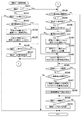
〔特図ゲーム処理〕
次に、前述のタイマ割込み処理における特図ゲーム処理(ステップS58)の詳細について説明する。特図ゲーム処理では、始動口1スイッチ36a及び始動口2スイッチ37aの入力の監視と、特図変動表示ゲームに関する処理全体の制御、特図の表示の設定を行う。
[Special Figure Game Processing]
Next, the details of the special game process (step S58) in the timer interrupt process described above will be described. In the special figure game process, the input of the
図15に示すように、特図ゲーム処理において、遊技制御装置100の遊技用マイコン111は、まず、始動口1スイッチ36a及び始動口2スイッチ37aの入賞を監視する始動口スイッチ監視処理(ステップA1)を行う。この始動口スイッチ監視処理では、第1始動入賞口をなす始動入賞口36、第2始動入賞口をなす普通変動入賞装置37に遊技球の入賞があると、各種乱数(大当り乱数など)の抽出を行い、当該入賞に基づく特図変動表示ゲームの開始前の段階で入賞に基づく遊技結果を事前に判定する遊技結果事前判定を行う。
As shown in FIG. 15, in the special game process, the
次いで、カウントスイッチ監視処理1(ステップA2)を行う。このカウントスイッチ監視処理1では、第1特別変動入賞装置38内に設けられたカウントスイッチ38a及び第2特別変動入賞装置39内に設けられたカウントスイッチ39aのカウント数を監視する処理を行う。
Next, the count switch monitoring process 1 (step A2) is performed. In the count
次いで、特図ゲーム処理タイマが、既にタイムアップしているか、又は、当該特図ゲーム処理タイマの更新(−1)によりタイムアップしたかをチェックして(ステップA3)、特図ゲーム処理タイマがタイムアップしたか否かを判定する(ステップA4)。ステップA4で、特図ゲーム処理タイマがタイムアップしたと判定した場合(ステップA4;Yes)には、特図ゲーム処理番号に対応する処理に分岐させるために参照する特図ゲームシーケンス分岐テーブルをレジスタに設定する処理(ステップA5)を行って、当該テーブルを用いて特図ゲーム処理番号に対応する処理の分岐先アドレスを取得する処理(ステップA6)を行う。次いで、分岐処理終了後のリターンアドレスをスタック領域に退避させる処理(ステップA7)を行った後、特図ゲーム処理番号に応じてゲーム分岐処理(ステップA8)を行う。 Next, it is checked whether the special figure game processing timer has already expired or the special figure game process timer has been updated (-1) (step A3). It is determined whether the time is up (step A4). If it is determined in step A4 that the special figure game process timer has expired (step A4; Yes), a special figure game sequence branch table to be referred to branch to the process corresponding to the special figure game process number is registered. (Step A5) is performed, and a process (step A6) of acquiring a branch destination address of the process corresponding to the special figure game process number is performed using the table. Next, after performing the process of saving the return address after the branch process to the stack area (step A7), the game branch process (step A8) is performed according to the special figure game process number.
ステップA8で、特図ゲーム処理番号が「0」の場合は、特図変動表示ゲームの変動開始を監視し、特図変動表示ゲームの変動開始の設定や演出の設定や、特図変動中処理を行うために必要な情報の設定等を行う特図普段処理(ステップA9)を行う。また、ステップA8で、特図ゲーム処理番号が「1」の場合は、特図の停止表示時間の設定や、特図表示中処理を行うために必要な情報の設定等を行う特図変動中処理(ステップA10)を行う。 If the special figure game process number is “0” in step A8, the fluctuation start of the special figure fluctuation display game is monitored, the fluctuation start setting of the special figure fluctuation display game, the setting of the production, the special figure fluctuation processing A special figure routine process (step A9) for setting information necessary for performing the process is performed. Also, if the special figure game process number is “1” in step A8, the special figure is changing to set the stop display time of the special figure or to set the information necessary for performing the special figure display process. Processing (step A10) is performed.
また、ステップA8で、特図ゲーム処理番号が「2」の場合は、特図変動表示ゲームの遊技結果が大当りであれば、大当りの種類に応じたファンファーレコマンドの設定や、各大当りの大入賞口開放パターンに応じたファンファーレ時間の設定や、ファンファーレ/インターバル中処理を行うために必要な情報の設定等を行う特図表示中処理(ステップA11)を行う。 In addition, when the special figure game process number is “2” in step A8, if the game result of the special figure fluctuation display game is a big hit, the fanfare command setting corresponding to the type of the big hit or the big win for each big hit A special chart display process (step A11) is performed for setting the fanfare time corresponding to the mouth opening pattern and setting information necessary for performing the fanfare / interval process.
また、ステップA8で、特図ゲーム処理番号が「3」の場合は、大入賞口の開放時間の設定や開放回数の更新、大入賞口開放中処理を行うために必要な情報の設定等を行うファンファーレ/インターバル中処理(ステップA12)を行う。また、ステップA8で、特図ゲーム処理番号が「4」の場合は、大当りラウンドが最終ラウンドでなければインターバルコマンドを設定する一方で最終ラウンドであればエンディングコマンドを設定する処理や、大入賞口残存球処理を行うために必要な情報の設定等を行う大入賞口開放中処理(ステップA13)を行う。 Also, if the special figure game process number is “3” in step A8, setting of the opening time of the big prize opening, updating of the number of times of opening, setting of information necessary for performing the processing during opening of the big prize opening, etc. The fanfare / interval processing (step A12) to be performed is performed. If the special figure game process number is “4” in step A8, an interval command is set if the big hit round is not the final round, while an ending command is set if the final round is a final round, A special winning opening opening process (step A13) for setting information necessary for performing the remaining ball process is performed.
また、ステップA8で、特図ゲーム処理番号が「5」の場合は、大当りラウンドが最終ラウンドであれば大入賞口内にある残存球が排出されるための時間を設定する処理や、大当り終了処理を行うために必要な情報の設定等を行う大入賞口残存球処理(ステップA14)を行う。また、ステップA8で、特図ゲーム処理番号が「6」の場合は、特図普段処理(ステップA9)を行うために必要な情報の設定等を行う大当り終了処理(ステップA15)を行う。 In step A8, when the special figure game process number is “5”, if the big hit round is the final round, a process for setting the time for discharging the remaining balls in the big prize opening, or a big hit end process The prize winning opening remaining ball process (step A14) for setting information necessary for performing the process is performed. If the special figure game process number is “6” in step A8, the big hit end process (step A15) for setting information necessary for performing the special figure normal process (step A9) is performed.
次いで、特図1表示器の変動を制御するためのテーブルを準備した後(ステップA16)、特図1表示器に係る図柄変動制御処理(ステップA17)を行う。次いで、特図2表示器の変動を制御するためのテーブルを準備した後(ステップA18)、特図2表示器に係る図柄変動制御処理(ステップA19)を行う。一方、ステップA4で、特図ゲーム処理タイマがタイムアップしていないと判定した場合(ステップA4;No)には、処理をステップA16に移行して、それ以降の処理を行う。 Next, after preparing a table for controlling the fluctuation of the special figure 1 display (step A16), the symbol fluctuation control process (step A17) related to the special figure 1 display is performed. Next, after preparing a table for controlling the fluctuation of the special figure 2 display (step A18), the symbol fluctuation control process (step A19) related to the special figure 2 display is performed. On the other hand, when it is determined in step A4 that the special figure game process timer has not expired (step A4; No), the process proceeds to step A16, and the subsequent processes are performed.
〔始動口スイッチ監視処理〕
次に、前述の特図ゲーム処理における始動口スイッチ監視処理(ステップA1)の詳細について説明する。図16に示すように、始動口スイッチ監視処理において、遊技制御装置100の遊技用マイコン111は、まず、第1始動口(始動入賞口36)による保留の情報を設定するテーブルを準備した後(ステップA111)、特図始動口スイッチ共通処理(ステップA112)を行う。
[Starter switch monitoring process]
Next, details of the start port switch monitoring process (step A1) in the above-described special figure game process will be described. As shown in FIG. 16, in the start port switch monitoring process, the
次いで、普通電動役物(普通変動入賞装置37)が作動中である、すなわち、普通変動入賞装置37が作動して遊技球の入賞が可能な開状態となっているか否かを判定する(ステップA113)。ステップA113で、普通電動役物が作動中であると判定した場合(ステップA113;Yes)には、処理をステップA116に移行して、それ以降の処理を行う。一方、ステップA113で、普通電動役物が作動中でないと判定した場合(ステップA113;No)には、普通変動入賞装置37への不正入賞数が不正発生判定個数以上であるかをチェックして(ステップA114)、不正入賞数が不正発生判定個数以上であるか否かを判定する(ステップA115)。普通変動入賞装置37は、閉状態では遊技球が入賞不可能であり、開状態でのみ遊技球が入賞可能である。よって、閉状態で遊技球が入賞した場合は何らかの異常や不正が発生した場合であり、このような閉状態で入賞した遊技球があった場合はその数を不正入賞数として計数する。そして、このように計数された不正入賞数が所定の不正発生判定個数(上限値)以上であるかが判定される。
Next, it is determined whether or not the ordinary electric winning component (ordinary variation winning device 37) is in operation, that is, whether or not the ordinary
ステップA115で、不正入賞数が不正判定個数以上でないと判定した場合(ステップA115;No)には、第2始動口(普通変動入賞装置37)による保留の情報を設定するテーブルを準備した後(ステップA116)、特図始動口スイッチ共通処理(ステップA117)を行って、始動口スイッチ監視処理を終了する。一方、ステップA115で、不正入賞数が不正判定個数以上であると判定した場合(ステップA115;Yes)には、始動口スイッチ監視処理を終了する。すなわち、第2始動記憶をそれ以上発生させないようにする。 If it is determined in step A115 that the number of fraudulent winnings is not equal to or greater than the number of fraud determinations (step A115; No), after preparing a table for setting information on hold by the second starting port (ordinary variable winning device 37) ( Step A116), special figure starting port switch common processing (step A117) is performed, and the starting port switch monitoring processing is terminated. On the other hand, if it is determined in step A115 that the number of fraudulent winnings is equal to or greater than the number of fraud determinations (step A115; Yes), the start port switch monitoring process is terminated. That is, the second start memory is not generated any more.
〔特図始動口スイッチ共通処理〕
次に、前述の始動口スイッチ監視処理における特図始動口スイッチ共通処理(ステップA112、A117)の詳細について説明する。特図始動口スイッチ共通処理は、始動口1スイッチ36aや始動口2スイッチ37aの入力があった場合に、各々の入力について共通して行われる処理である。
[Special figure start port switch common processing]
Next, details of the special-purpose start-port switch common processing (steps A112 and A117) in the above-described start-port switch monitoring processing will be described. The special figure start port switch common process is a process performed in common for each input when there is an input from the
図17に示すように、特図始動口スイッチ共通処理において、遊技制御装置100の遊技用マイコン111は、まず、始動口1スイッチ36a及び始動口2スイッチ37aのうち、監視対象の始動口スイッチ(例えば、始動口1スイッチ36a等)に入力があるかをチェックして(ステップA201)、監視対象の始動口スイッチに入力があるか否かを判定する(ステップA202)。ステップA202で、監視対象の始動口スイッチに入力がないと判定した場合(ステップA202;No)には、特図始動口スイッチ共通処理を終了する。一方、ステップA202で、監視対象の始動口スイッチに入力があると判定した場合(ステップA202;Yes)には、当該監視対象の始動口スイッチの始動口入賞フラグをセーブした後(ステップA203)、当該監視対象のハード乱数ラッチレジスタに抽出された大当り乱数をロードし、準備する(ステップA204)。
As shown in FIG. 17, in the special figure start port switch common process, the
次いで、始動口1スイッチ36a及び始動口2スイッチ37aのうち、監視対象の始動口スイッチ(例えば、始動口1スイッチ36a等)への入賞の回数に関する情報が遊技機10の外部の管理装置に対して出力された回数(始動口信号出力回数)をロードする(ステップA205)。次いで、始動口信号出力回数を更新(+1)して出力回数がオーバーフローするかをチェックし(ステップA206)、出力回数がオーバーフローするか否かを判定する(ステップA207)。ステップA207で、出力回数がオーバーフローしないと判定した場合(ステップA207;No)には、更新後の値をRWMの始動口信号出力回数領域にセーブして(ステップA208)、処理をステップA209に移行する。一方、ステップA207で、出力回数がオーバーフローすると判定した場合(ステップA207;Yes)には、処理をステップA209に移行する。
Next, of the
そして、始動口1スイッチ36a及び始動口2スイッチ37aのうち、監視対象の始動口スイッチ(例えば、始動口1スイッチ36a等)に対応する更新対象の特図保留(始動記憶)数が上限値未満かをチェックして(ステップA209)、特図保留数が上限値未満か否かを判定する(ステップA210)。
And, among the
ステップA210で、特図保留数が上限値未満であると判定した場合(ステップA210;Yes)には、更新対象の特図保留数(例えば、特図1保留数等)を更新(+1)する処理(ステップA215)を行う。次いで、始動口1スイッチ36a及び始動口2スイッチ37aのうち、監視対象の始動口スイッチ(例えば、始動口1スイッチ36a等)の飾り特図保留数コマンド(MODE)を準備した後(ステップA216)、特図保留数に対応する飾り特図保留数コマンド(ACTION)を準備して(ステップA217)、コマンド設定処理(ステップA218)を行う。次いで、特図保留数に対応する乱数セーブ領域のアドレスを算出して(ステップA219)、大当り乱数をRWMの大当り乱数セーブ領域にセーブする(ステップA220)。
If it is determined in step A210 that the number of special figure hold is less than the upper limit (step A210; Yes), the number of special figure hold to be updated (for example, the number of special figure hold 1) is updated (+1). Processing (step A215) is performed. Next, after preparing the decoration special figure reservation number command (MODE) of the start port switch to be monitored (for example, the
次いで、当該監視対象の始動口スイッチの大当り図柄乱数を抽出して準備し(ステップA221)、RWMの大当り図柄乱数セーブ領域にセーブする(ステップA222)。次いで、対応する変動パターン乱数1から3を抽出してRWMの各乱数のセーブ領域にセーブし(ステップA223、A224、A225)、特図保留情報判定処理(ステップA226)を行って、特図始動口スイッチ共通処理を終了する。
Next, the big hit symbol random number of the start port switch to be monitored is extracted and prepared (step A221), and saved in the big hit symbol random number saving area of the RWM (step A222). Next, the corresponding variation pattern
一方、ステップA210で、特図保留数が上限値未満でないと判定した場合(ステップA210;No)には、ステップA202に係る始動口スイッチの入力が始動口1スイッチ36aの入力であるかをチェックして(ステップA211)、始動口1スイッチ36aの入力であるか否かを判定する(ステップA212)。ステップA212で、始動口1スイッチ36aの入力であると判定した場合(ステップA212;Yes)には、飾り特図保留数コマンド(保留オーバーフローコマンド)を準備し(ステップA213)、コマンド設定処理(ステップA214)を行って、特図始動口スイッチ共通処理を終了する。一方、ステップA212で、始動口1スイッチ36aの入力でないと判定した場合(ステップA212;No)には、特図始動口スイッチ共通処理を終了する。
On the other hand, if it is determined in step A210 that the special figure hold number is not less than the upper limit (step A210; No), it is checked whether the input of the start port switch according to step A202 is the input of the
〔特図保留情報判定処理〕
次に、前述の始動口スイッチ共通処理における特図保留情報判定処理(ステップA226)の詳細について説明する。特図保留情報判定処理は、対応する始動記憶に基づく特図変動表示ゲームの開始タイミングより前に当該始動記憶に対応した結果関連情報の判定を行う先読み処理である。
[Special figure hold information judgment processing]
Next, the details of the special figure hold information determination process (step A226) in the above-described start port switch common process will be described. The special figure hold information determination process is a look-ahead process for determining the result related information corresponding to the start memory before the start timing of the special figure variation display game based on the corresponding start memory.
図18に示すように、特図保留情報判定処理において、遊技制御装置100の遊技用マイコン111は、まず、始動口2の入賞(普通変動入賞装置37への入賞)であるか否かを判定する(ステップA231)。ステップA231で、始動口2の入賞であると判定した場合(ステップA231;Yes)には、高確率時(高確率状態)であるか否かの判定を行う(ステップA233)。一方、ステップA231で、始動口2の入賞でないと判定した場合(ステップA231;No)には、電サポ(時短状態)又は大当り(特別遊技状態)中であるか否かを判定する(ステップA232)。
As shown in FIG. 18, in the special figure hold information determination process, the
ステップA232で、電サポ又は大当り中であると判定した場合(ステップA232;Yes)には、特図保留情報判定処理を終了する。一方、ステップA232で、電サポ又は大当り中でないと判定した場合(ステップA232;No)には、高確率時(高確率状態)であるか否かの判定を行う(ステップA233)。 If it is determined in step A232 that the electric support or big hit is being made (step A232; Yes), the special figure hold information determination process is terminated. On the other hand, if it is determined in step A232 that there is no power support or big hit (step A232; No), it is determined whether or not it is a high probability (high probability state) (step A233).
ステップA233で、高確率時であると判定した場合(ステップA233;Yes)には、高確率時の判定値を設定し(ステップA234)、対象の大当り乱数をロードする(ステップA236)。そして、大当り乱数値が大当り判定値と一致するか否かによって大当りであるか否かを判定する(ステップA237)。一方、ステップA233で、高確率時でないと判定した場合(ステップA233;No)には、低確率時(通常確率状態)の判定値を設定し(ステップA235)、対象の大当り乱数をロードする(ステップA236)。そして、大当り乱数値が大当り判定値と一致するか否かによって大当りであるか否かを判定する(ステップA237)。 If it is determined in step A233 that the probability is high (step A233; Yes), a determination value for high probability is set (step A234), and the target big hit random number is loaded (step A236). Then, it is determined whether or not the jackpot is a big hit based on whether or not the jackpot random number value matches the jackpot determination value (step A237). On the other hand, if it is determined in step A233 that it is not a high probability (step A233; No), a determination value for a low probability (normal probability state) is set (step A235), and the target big hit random number is loaded (step A235). Step A236). Then, it is determined whether or not the jackpot is a big hit based on whether or not the jackpot random number value matches the jackpot determination value (step A237).
ステップA237で、大当りであると判定した場合(ステップA237;Yes)には、対象の始動口スイッチに対応する大当り図柄情報テーブル(図20参照)を設定し(ステップA238)、対象の大当り図柄乱数をロードする(ステップA239)。その後、設定した大当り図柄情報テーブルから大当り図柄乱数に対応する図柄情報を取得し(ステップA240)、取得した図柄情報に対応する図柄情報コマンドを準備して(ステップA242)、コマンド設定処理を行う(ステップA243)。一方、ステップA237で、大当りでないと判定した場合(ステップA237;No)には、はずれ図柄情報を取得し(ステップA241)、取得した図柄情報に対応する図柄情報コマンドを準備して(ステップA242)、コマンド設定処理を行う(ステップA243)。 When it is determined in step A237 that it is a big hit (step A237; Yes), a big hit symbol information table (see FIG. 20) corresponding to the target start-up switch is set (step A238), and the target big hit symbol random number is set. Is loaded (step A239). Thereafter, symbol information corresponding to the jackpot symbol random number is acquired from the set jackpot symbol information table (step A240), a symbol information command corresponding to the acquired symbol information is prepared (step A242), and command setting processing is performed (step A240). Step A243). On the other hand, when it is determined in step A237 that the game is not a big hit (step A237; No), the symbol information is obtained (step A241), and the symbol information command corresponding to the acquired symbol information is prepared (step A242). Then, command setting processing is performed (step A243).
次いで、対象の変動パターン乱数1をロードし(ステップA244)、対象の変動パターン乱数1に対応する変動パターン乱数コマンドを準備して(ステップA245)、コマンド設定処理を行い(ステップA246)、特図保留情報判定処理を終了する。この処理により、始動記憶の発生に基づき、演出制御装置300に対して飾り特図保留数コマンドが送信され、その後、事前判定情報(事前判定コマンド)として特図種別・図柄情報コマンドと変動パターン乱数コマンドとが送信される。そして、演出制御装置300では、飾り特図保留数コマンドに基づき特図始動記憶数を増加し、図柄情報コマンド及び変動パターン乱数コマンドに基づき事前演出(先読み演出)を行う。
Next, the target variation pattern
すなわち、始動記憶に対応した結果関連情報の判定結果(先読み結果)を、対応する始動記憶に基づく特図変動表示ゲームの開始タイミングより前に演出制御装置300に対して知らせることができる。そして、演出制御装置300は、表示装置41に表示される飾り特図始動記憶表示mを変化させるなどして、その特図変動表示ゲームの開始タイミングより前に遊技者に結果関連情報を報知することが可能となる。
That is, the determination result (prefetch result) of the result related information corresponding to the start memory can be notified to the
ここで、秘匿性を高める必要がある(結果に影響を及ぼす)大当り乱数及び大当り図柄乱数については、判定後の結果情報を図柄情報コマンドとして演出制御装置300に送信している。これに対して秘匿性を高める必要のない(結果に影響を及ぼさない)変動パターン乱数については変動パターン乱数コマンドとして、乱数値のまま、若しくは、乱数値を示す情報に変換して演出制御装置300に送信するようにしている。なお、変動パターン乱数1は後半変動のリーチ系統(変動グループ)を選択するための乱数であり、変動パターン乱数2はリーチ系統の中から詳細な演出の振分を行うための乱数であり、変動パターン乱数3は前半変動を選択するための乱数である。事前判定時点ではリーチ系統さえ演出制御装置300側に伝達できれば良いので、変動パターン乱数1に関する情報を送信すれば良い。
Here, for jackpot random numbers and jackpot symbol random numbers that need to improve confidentiality (influence the results), the result information after determination is transmitted to the
なお、始動記憶に対応して記憶された乱数値を事前に判定する時期は、当該始動記憶が発生した始動入賞時だけではなく、当該始動記憶に基づく変動表示ゲームが行われる前であればいつでもよい。また、変動パターン乱数2及び変動パターン乱数3を変動パターン乱数コマンドに含めるようにしても良いし、変動パターン乱数コマンドに代えて変動パターン乱数1〜3により判定した変動パターンを示すコマンドを送信するようにしても良い。すなわち、変動パターン乱数1〜3を全て演出制御装置300に送信しても良いし、変動開始時のように変動パターンを決定してから変動パターン番号を演出制御装置300に送信するようにしても良い。
Note that the time when the random number value stored in correspondence with the start memory is determined in advance is not only at the start winning time when the start memory is generated, but any time before the variable display game based on the start memory is performed. Good. Further, the variation pattern
〔特図普段処理〕
次に、前述の特図ゲーム処理における特図普段処理(ステップA9)の詳細について説明する。図19に示すように、特図普段処理において、遊技制御装置100の遊技用マイコン111は、まず、特図2保留数(第2始動記憶数)が0であるかをチェックして(ステップA301)、特図2保留数が0であるか否かを判定する(ステップA302)。ステップA302で、特図2保留数が0であると判定した場合(ステップA302;Yes)には、特図1保留数(第1始動記憶数)が0であるかをチェックして(ステップA303)、特図1保留数が0であるか否かを判定する(ステップA304)。ステップA304で、特図1保留数が0であると判定した場合(ステップA304;Yes)には、既に客待ちデモが開始されているかをチェックして(ステップA305)、既に客待ちデモが開始されているか否か、すなわち、客待ちデモが開始済みであるか否かを判定する(ステップA306)。
[Special figure routine processing]
Next, the details of the special figure routine process (step A9) in the special figure game process described above will be described. As shown in FIG. 19, in the special figure normal processing, the
ステップA306で、客待ちデモが開始済みでないと判定した場合(ステップA306;No)には、客待ちデモフラグ領域に客待ちデモ中フラグをセーブする(ステップA307)。そして、客待ちデモコマンドを準備して(ステップA308)、コマンド設定処理(ステップA309)、特図普段処理移行設定処理1(ステップA310)を行って、特図普段処理を終了する。一方、ステップA306で、客待ちデモが開始済みであると判定した場合(ステップA306;Yes)には、既に客待ちデモフラグ領域に客待ちデモ中フラグがセーブ(ステップA307)され、客待ちデモコマンドも準備(ステップA308)され、コマンド設定処理(ステップA309)も実行されているため、これらの処理を行わずに特図普段処理移行設定処理1(ステップA310)を行い、特図普段処理を終了する。この特図普段処理移行設定処理1では、特図普段処理に係る処理番号「0」、大入賞口不正監視期間を規定するフラグ(大入賞口不正監視情報)等を設定する処理を行う。
If it is determined in step A306 that the customer waiting demo has not been started (step A306; No), a customer waiting demo flag is saved in the customer waiting demo flag area (step A307). Then, the customer waiting demonstration command is prepared (step A308), the command setting process (step A309), the special figure normal process transition setting process 1 (step A310) is performed, and the special figure normal process is terminated. On the other hand, if it is determined in step A306 that the customer waiting demo has been started (step A306; Yes), the customer waiting demo flag is already saved in the customer waiting demo flag area (step A307), and the customer waiting demo command is displayed. Is also prepared (step A308) and the command setting process (step A309) is also executed, so the special figure normal process transition setting process 1 (step A310) is performed without performing these processes, and the special figure normal process is terminated. To do. In the special figure normal process
また、ステップA302で特図2保留数が0でないと判定した場合(ステップA302;No)や、ステップA304で特図1保留数が0でないと判定した場合(ステップA304;No)には、特図変動表示ゲームが大当りであるか否かを判定するための大当りフラグにはずれ情報や大当り情報を設定する大当りフラグ設定処理(ステップA311)を行う。 In addition, when it is determined in step A302 that the special figure 2 hold number is not 0 (step A302; No) or in step A304, it is determined that the special figure 1 hold number is not 0 (step A304; No), A jackpot flag setting process (step A311) is performed to set shift information and jackpot information to the jackpot flag for determining whether or not the figure variation display game is a jackpot.
次いで、特図停止図柄(図柄情報)の設定に係る処理、具体的には、大当りフラグの有無及び図柄乱数に基づいて特図停止図柄を決定する処理である特図停止図柄設定処理(ステップA312)を行った後、設定された特図停止図柄の特図停止図柄番号に対応する信号を試験信号出力データ領域にセーブし(ステップA313)、図柄情報を特図(特図1又は特図2)に対応する図柄情報(作業用)領域にセーブする(ステップA314)。 Next, a special symbol stop symbol setting process (step A312), which is a process related to setting a special symbol stop symbol (symbol information), specifically, a special symbol stop symbol determination process based on the presence / absence of a jackpot flag and a symbol random number. ), The signal corresponding to the special figure stop symbol number of the special figure stop symbol that has been set is saved in the test signal output data area (step A313), and the symbol information is saved as the special symbol (Special Fig. 1 or Special Fig. 2). ) Is saved in the symbol information (work) area corresponding to ().
次いで、特図(特図1又は特図2)に対応する特図変動フラグを変動図柄判別フラグ領域にセーブし(ステップA315)、変動パターンに関する情報を設定するテーブルを準備する(ステップA316)。次いで、特図変動表示ゲームの変動態様を設定する変動パターン設定処理(ステップA317)、変動開始の情報を設定する変動開始情報設定処理(ステップA318)を行う。この変動開始情報設定処理では、特図変動表示ゲームの変動パターンに関する情報を含む変動パターンコマンド、飾り特図変動表示ゲームに係る停止図柄パターン(停止結果態様)情報に対応する飾り特図コマンド、表示装置41に表示される飾り特図始動記憶表示mに係る飾り特図保留数コマンド(飾り特図保留数コマンド)を準備する。これらのコマンドは後に演出制御装置300に送信される。
Next, the special figure fluctuation flag corresponding to the special figure (special figure 1 or special figure 2) is saved in the fluctuation symbol discrimination flag area (step A315), and a table for setting information regarding the fluctuation pattern is prepared (step A316). Next, a variation pattern setting process (step A317) for setting a variation mode of the special figure variation display game and a variation start information setting process (step A318) for setting variation start information are performed. In this variation start information setting process, a variation pattern command including information related to a variation pattern of the special-figure variation display game, a special-decoration diagram command corresponding to the stop symbol pattern (stop result mode) information related to the special-figure special-figure display game, and display A decoration special figure reservation number command (decoration special figure reservation number command) related to the decoration special figure start memory display m displayed on the
次いで、特図変動中処理移行設定処理(ステップA319)を行って、特図普段処理を終了する。この特図変動中処理移行設定処理では、特図変動中処理に係る処理番号「1」、客待ちデモの終了に係る情報、第1特図の変動中に係る試験信号又は第2特図の変動中に係る試験信号、特図1表示器における第1特図変動表示ゲームの制御用の情報(例えば、特図1表示器の変動中に係るフラグ、特図1表示器の点滅の周期のタイマの初期値など)又は特図2表示器における第2特図変動表示ゲームの制御用の情報(例えば、特図2表示器の変動中に係るフラグ、特図2表示器の点滅の周期のタイマの初期値など)等を設定する処理を行う。 Subsequently, the special figure changing process transition setting process (step A319) is performed, and the special figure usual process is terminated. In the special figure changing process transition setting process, the process number “1” relating to the special figure changing process, the information relating to the end of the customer waiting demonstration, the test signal relating to the change of the first special figure, or the second special figure Test signal during fluctuation, information for controlling the first special figure fluctuation display game in the special figure 1 display (for example, flag relating to fluctuation of the special figure 1 display, period of blinking of the special figure 1 display) The initial value of the timer, etc.) or information for controlling the second special figure fluctuation display game in the special figure 2 display (for example, the flag relating to the fluctuation of the special figure 2 display, the blinking cycle of the special figure 2 display) Perform processing to set the initial value of the timer.
このように、ステップA301とステップA302における特図2保留数のチェックを、ステップA303とステップA304における特図1保留数のチェックよりも先に行うことで、特図2保留数が0でない場合には、第2始動記憶に基づく大当りフラグ設定処理(ステップA311)から特図変動中処理移行設定処理(ステップA319)が実行され、特図2保留数が0であり特図1保留数が0でない場合には、第1始動記憶に基づく大当りフラグ設定処理(ステップA311)から特図変動中処理移行設定処理(ステップA319)が実行されることとなる。すなわち、第2特図変動表示ゲームが第1特図変動表示ゲームに優先して実行されることとなる。 In this way, when the special figure 2 hold number in step A301 and step A302 is checked before the special figure 1 hold number check in steps A303 and A304, the special figure 2 hold number is not zero. Is executed from the big hit flag setting process (step A311) based on the second start memory to the special figure changing process transition setting process (step A319), the special figure 2 hold number is 0 and the special figure 1 hold number is not 0. In this case, the special chart changing process transition setting process (step A319) is executed from the big hit flag setting process (step A311) based on the first start memory. That is, the second special figure variation display game is executed with priority over the first special figure variation display game.
図20には、結果が特別結果(大当り)である場合に特別結果の種類を決定するための大当り図柄情報テーブルを示した。図20(a)は第1特図変動表示ゲームに対応する大当り図柄情報テーブルであり、図20(b)は第2特図変動表示ゲームに対応する大当り図柄情報テーブルである。 FIG. 20 shows a jackpot symbol information table for determining the type of special result when the result is a special result (big hit). FIG. 20A is a jackpot symbol information table corresponding to the first special symbol variation display game, and FIG. 20B is a jackpot symbol information table corresponding to the second special symbol variation display game.
特別結果には、特別遊技状態の実行態様や特別遊技状態の終了後に遊技者に付与される付加遊技価値等の遊技価値が異なる複数種類が設定されており、遊技制御装置100では始動口への遊技球の入賞に基づき抽出された大当り図柄乱数に基づき特別結果を選択する。すなわち、大当り図柄乱数に基づき特別遊技状態の実行態様や付加遊技価値の量が決定されるといえる。本実施形態の遊技機10における特別遊技状態の実行態様とは、実行可能なラウンド数や大入賞口の開放可能時間(すなわち、特別遊技状態で獲得可能な遊技球(賞球)の数)や開放する大入賞口の種類(上AT(第2特別変動入賞装置39)、下AT(第1特別変動入賞装置38))である。また、付加遊技価値とは、特別遊技状態の終了後に次回の特別結果態様の導出まで遊技状態を高確率状態とすることや、特別遊技状態の終了後に所定回数の特図変動表示ゲームを実行するまで時短状態とすることである。また、大当り図柄乱数に基づいて、特別遊技状態の終了後に確率状態を報知する(確率明瞭)か報知しない(確率曖昧)かも決定される。
In the special result, a plurality of types having different game values such as an execution mode of the special game state and an additional game value given to the player after the end of the special game state are set. A special result is selected based on the jackpot symbol random number extracted based on the winning of the game ball. That is, it can be said that the execution mode of the special gaming state and the amount of additional game value are determined based on the jackpot symbol random number. The execution mode of the special game state in the
大当り図柄乱数が1から20である場合には、上AT(第2特別変動入賞装置39)の開放が選択される。この場合、一のラウンド(R)において所定の閉鎖時間を挟んで3回の開放が行われるようになっており、例えば3ラウンドを実行する場合は9回の開放が行われる。後述するように、上AT(第2特別変動入賞装置39)が開放される特別結果となる特図変動表示ゲームでは、この開放回数を示唆する補助ゲームが行われる。ただし、補助ゲームにおいては実際の開放回数よりも少ない開放回数が示唆される場合もある。 When the jackpot symbol random number is 1 to 20, the opening of the upper AT (second special variable winning device 39) is selected. In this case, the opening is performed three times with a predetermined closing time in one round (R). For example, when three rounds are executed, the opening is performed nine times. As will be described later, in the special figure variation display game that has a special result in which the upper AT (second special variation prize winning device 39) is released, an auxiliary game that suggests the number of times of opening is performed. However, in the auxiliary game, the number of times of opening may be suggested that is less than the actual number of times of opening.
これらの大当りのうち、確変3R大当りと確変12R大当り、確変6R大当りと確変9R大当りは、飾り特図変動表示ゲームの結果態様のうち、表示装置41での結果態様は同一であり、包囲枠体40に設けられた左上発光装置621、左下発光装置622、右上発光装置623及び右下発光装置624の変化表示部673での表示態様のみが異なる(図45、図46参照)。これらは変化表示部673での表示態様か、特図1表示器、特図2表示器の表示態様でのみ判別可能であり、何れの大当りであるかが識別し難くされている。これにより、特別遊技状態中において、補助ゲームで示唆された開放回数よりも多い開放回数となることを遊技者に期待させ、遊技の興趣を高めるようにしている。
Among these jackpots, the
また、大当り図柄乱数が31から35である場合(確変2R大当り)と、大当り図柄乱数が46から50である場合(通常2R大当り)は、特別遊技状態の終了後に確率状態を明確に報知しない確率曖昧状態となる。これらの大当りでは、飾り特図変動表示ゲームの結果態様のうち、表示装置41での結果態様は同一であり、包囲枠体40に設けられた左上発光装置621、左下発光装置622、右上発光装置623及び右下発光装置624の変化表示部673での表示態様のみが異なり(図45、図46参照)、特別遊技状態の実行態様も同一である。これらは変化表示部673での表示態様か、特図1表示器、特図2表示器の表示態様でのみ判別可能であり、何れの大当りであるかが識別し難くされている。これにより、確率曖昧状態において高確率状態であることを遊技者に期待させ、遊技の興趣を高めるようにしている。また、特別結果の振り分けは、第1特図変動表示ゲームよりも第2特図変動表示ゲームの方が遊技者にとって有利な特別結果が選択される確率が高くなるようにされている。
In addition, when the jackpot symbol random number is 31 to 35 (
〔変動パターン設定処理〕
次に、前述の特図普段処理における変動パターン設定処理(ステップA317)の詳細について説明する。図21に示すように、変動パターン設定処理において、遊技制御装置100の遊技用マイコン111は、まず、図柄情報(作業用)がはずれ図柄情報であるかをチェックして(ステップA321)、はずれ図柄情報であるか否かを判定する(ステップA322)。
[Variation pattern setting process]
Next, the details of the variation pattern setting process (step A317) in the above-described special figure routine process will be described. As shown in FIG. 21, in the variation pattern setting process, the
ステップA322で、はずれ図柄情報であると判定した場合(ステップA322;Yes)には、現在の遊技状態に対応する変動グループ選択テーブル(図23、図24参照)を準備して(ステップA323)、対象の領域から変動パターン乱数1をロードして準備する(ステップA325)。一方、ステップA322で、はずれ図柄情報でないと判定した場合(ステップA322;No)には、特図(特図1又は特図2)に対応する大当り時の変動グループ選択テーブル(図22参照)を準備して(ステップA324)、対象の領域から変動パターン乱数1をロードして準備する(ステップA325)。
If it is determined in step A322 that the symbol information is out of place (step A322; Yes), a variation group selection table (see FIGS. 23 and 24) corresponding to the current gaming state is prepared (step A323). The fluctuation pattern
次いで、2バイト振り分け処理(ステップA326)を行い、振り分けた結果得られたリーチ系統のアドレスを取得して準備する(ステップA327)。次いで、対象の領域から変動パターン乱数2をロードして準備し(ステップA328)、振り分け処理(ステップA329)を行って、振り分けた結果得られた後半変動番号を取得する(ステップA330)。次いで、後半変動番号を対象の後半変動番号領域にセーブし(ステップA331)、後半変動番号がリーチなし変動の番号かをチェックして(ステップA332)、リーチなし変動の番号であるか否かを判定する(ステップA333)。
Next, a 2-byte distribution process (step A326) is performed, and the address of the reach system obtained as a result of the distribution is acquired and prepared (step A327). Next, the fluctuation pattern
ステップA333で、リーチなし変動の番号であると判定した場合(ステップA333;Yes)には、前半変動選択テーブル1(リーチなし用)を準備し(ステップA334)、対象の領域から変動パターン乱数3をロードして準備する(ステップA336)。一方、ステップA333で、リーチなし変動の番号でないと判定した場合(ステップA333;No)には、前半変動選択テーブル2(リーチ用)を準備し(ステップA335)、対象の領域から変動パターン乱数3をロードして準備する(ステップA336)。
When it is determined in step A333 that the number is a variation without reach (step A333; Yes), the first half variation selection table 1 (for no reach) is prepared (step A334), and the variation pattern
次いで、振り分け処理を行い(ステップA337)、振り分けた結果得られた前半変動番号を取得して準備し(ステップA338)、変動パターン設定処理を終了する。以上の処理により、変動パターン乱数1に基づき変動グループ(リーチなし、ノーマルリーチ、SP1〜4リーチの何れか)が選択され、変動パターン乱数2に基づき変動グループの中から詳細な演出の振り分け(変動パターンの選択)が行われるとともに、変動パターン乱数3に基づきリーチ状態となるまでの前半変動の変動態様が選択される。
Next, a sorting process is performed (step A337), and the first half variation number obtained as a result of the sorting is acquired and prepared (step A338), and the variation pattern setting process is terminated. Through the above processing, a variation group (no reach, normal reach, or SP1 to 4 reach) is selected based on the variation pattern
図22に示す大当り時の変動グループ選択テーブルでは、リーチ状態となる変動グループのみが選択可能である。また、第2特図変動表示ゲームの場合のみSP4リーチが選択可能である。図23、図24に示す第1特図変動表示ゲームのはずれ時の変動グループ選択テーブル及び第2特図変動表示ゲームのはずれ時の変動グループ選択テーブルでは、時短状態(普電サポート状態)であるか否かにより使用するテーブルが異なり、時短状態(普電サポート状態、低サポ)でない場合(普図低確率状態である場合)は図23のテーブルを用い、時短状態である場合(普図高確率状態である場合、高サポ)は図24のテーブルを用いる。 In the variation group selection table at the time of big hit shown in FIG. 22, only the variation group that reaches the reach state can be selected. Also, SP4 reach can be selected only in the case of the second special figure variation display game. The fluctuation group selection table at the time of losing of the first special figure fluctuation display game and the fluctuation group selection table at the time of losing of the second special figure fluctuation display game shown in FIG. 23 and FIG. 24 are in a short time state (normal power support state). The table to be used differs depending on whether or not it is in the short-time state (general power support state, low support) (when the normal figure low probability state), the table of FIG. In the case of the probability state, the table of FIG. 24 is used for high support.
図23(a)、(b)に示す時短状態でない場合における第1特図変動表示ゲームのはずれ時の変動グループ選択テーブルでは、第1始動記憶数によって使用するテーブルが異なっている。時短状態でない場合は、第1始動記憶数が1である時、すなわち、第1特図変動表示ゲームの開始により第1始動記憶数が1から0になる時に、当該特図変動表示ゲームについて図23(a)のテーブルを用い、第1始動記憶数が2、3又は4である時に図23(b)のテーブルを用いる。第1始動記憶数が多いほどリーチなし及びノーマルリーチの変動時間が短くされており、迅速に第1始動記憶を消化できるようにされている。 In the variation group selection table at the time of the failure of the first special figure variation display game in the case of not being in the short time state shown in FIGS. 23A and 23B, the table to be used differs depending on the first start memory number. If it is not in the short-time state, when the first start memory number is 1, that is, when the first start memory number is changed from 1 to 0 by the start of the first special figure variable display game, the special figure variable display game is displayed. 23 (a) is used, and the table of FIG. 23 (b) is used when the first start memory number is 2, 3 or 4. The larger the first start memory number, the shorter the reach time and the normal reach variation time, so that the first start memory can be quickly digested.
また、図23(c)、(d)に示す時短状態でない場合における第2特図変動表示ゲームのはずれ時の変動グループ選択テーブルでも同様に、第2始動記憶数によって使用するテーブルが異なっている。時短状態でない場合は、第2始動記憶数が1である時、すなわち、第2特図変動表示ゲームの開始により第2始動記憶数が1から0になる時に、当該特図変動表示ゲームについて図23(c)のテーブルを用い、第2始動記憶数が2、3又は4である時に図23(d)のテーブルを用いる。第2始動記憶数が多いほどリーチなし及びノーマルリーチの変動時間が短くされており、迅速に第2始動記憶を消化できるようにされている。 Similarly, in the variation group selection table at the time of the loss of the second special figure variation display game in the case where the time reduction state is not shown in FIGS. . If it is not in the short-time state, when the second start memory number is 1, that is, when the second start memory number becomes 1 to 0 by the start of the second special figure variable display game, 23 (c) is used, and when the second start memory number is 2, 3 or 4, the table of FIG. 23 (d) is used. The larger the second start memory number, the shorter the reach time of no reach and normal reach, so that the second start memory can be quickly digested.
また、図24(a)、(b)に示す時短状態である場合における第1特図変動表示ゲームのはずれ時の変動グループ選択テーブルでは、第1始動記憶数が1である時、すなわち、第1特図変動表示ゲームの開始により第1始動記憶数が1から0になる時に、当該特図変動表示ゲームについて図24(a)のテーブルを用い、第1始動記憶数が2、3又は4である時に図24(b)のテーブルを用いる。この場合も、第1始動記憶数が多い場合の方がリーチなし及びノーマルリーチの変動時間が短くされており、迅速に第1始動記憶を消化できるようにされている。また、第1始動記憶数が1である場合におけるリーチなしの変動時間は、時短状態でない場合におけるリーチなしの変動時間よりも長く、遊技者にとって通常遊技状態よりも有利な時短状態において特図変動表示ゲームが途切れてしまうことを防止するようにしている。 In the variation group selection table when the first special figure variation display game is lost in the short time state shown in FIGS. 24A and 24B, the first start memory number is 1, that is, the first When the first start memory number is changed from 1 to 0 by the start of one special figure variation display game, the first start memory number is 2, 3 or 4 using the table of FIG. At that time, the table of FIG. 24B is used. Also in this case, when the number of first start memories is large, there is no reach and the fluctuation time of normal reach is shortened, so that the first start memories can be quickly digested. In addition, the fluctuation time without reach when the first start memory number is 1 is longer than the fluctuation time without reach when not in the short-time state, and the special time fluctuation in the short-time state which is advantageous to the player over the normal gaming state The display game is prevented from being interrupted.
また、図24(c)、(d)に示す時短状態である場合における第2特図変動表示ゲームのはずれ時の変動グループ選択テーブルでは、第2始動記憶数が1である時、すなわち、第2特図変動表示ゲームの開始により第2始動記憶数が1から0になる時に、当該特図変動表示ゲームについて図24(c)のテーブルを用い、第2始動記憶数が2、3又は4である時に図24(d)のテーブルを用いる。この場合も、第2始動記憶数が多い場合の方がリーチなし及びノーマルリーチの変動時間が短くされており、迅速に第2始動記憶を消化できるようにされている。 Also, in the variation group selection table at the time of losing of the second special figure variation display game in the short time state shown in FIGS. 24C and 24D, when the second start memory number is 1, that is When the second start memory number is changed from 1 to 0 by the start of the 2 special figure variation display game, the second start memory number is 2, 3 or 4 using the table of FIG. At that time, the table of FIG. Also in this case, when the number of second start memories is large, there is no reach and the fluctuation time of normal reach is shortened, so that the second start memories can be quickly digested.
〔変動開始情報設定処理〕
次に、前述の特図普段処理における変動開始情報設定処理(ステップA318)の詳細について説明する。図25に示すように、変動開始情報設定処理において、遊技制御装置100の遊技用マイコン111は、まず、対象の変動パターン乱数1〜3の乱数セーブ領域を0クリアする(ステップA401)。次いで、前半変動時間値テーブルを設定し(ステップA402)、前半変動番号に対応する前半変動時間値を取得する(ステップA403)。次いで、後半変動時間値テーブルを設定し(ステップA404)、後半変動番号に対応する後半変動時間値を取得する(ステップA405)。
[Variation start information setting process]
Next, details of the change start information setting process (step A318) in the above-described special figure routine process will be described. As shown in FIG. 25, in the change start information setting process, the
次いで、前半変動時間値と後半変動時間値を加算し(ステップA406)、加算値を特図ゲーム処理タイマ領域にセーブする(ステップA407)。次いで、前半変動番号に対応する変動コマンド(MODE)を算出して準備し(ステップA408)、後半変動番号の値を変動コマンド(ACTION)として準備して(ステップA409)、コマンド設定処理を行う(ステップA410)。 Next, the first half variation time value and the second half variation time value are added (step A406), and the added value is saved in the special figure game process timer area (step A407). Next, a variation command (MODE) corresponding to the first half variation number is calculated and prepared (step A408), and the second half variation number is prepared as a variation command (ACTION) (step A409), and command setting processing is performed (step A409). Step A410).
次いで、飾り特図コマンド領域から図柄情報コマンドをロードして準備し(ステップA411)、コマンド設定処理を行う(ステップA412)。次いで、変動図柄判別フラグに対応する飾り特図保留数コマンド(MODE)を準備し(ステップA413)、変動図柄判別フラグに対応する乱数セーブ領域のアドレスを設定して(ステップA414)、変動図柄判別フラグに対応する特図保留数を−1更新する(ステップA415)。次いで、特図保留数に対応する飾り特図保留数コマンド(ACTION)を準備し(ステップA416)、コマンド設定処理を行う(ステップA417)。次いで、変動図柄判別フラグに対応する乱数セーブ領域をシフトし(ステップA418)、シフト後の空き領域を0クリアして(ステップA419)、変動開始情報設定処理を終了する。 Next, a symbol information command is loaded and prepared from the decoration special figure command area (step A411), and command setting processing is performed (step A412). Next, a decoration special figure holding number command (MODE) corresponding to the variation symbol discrimination flag is prepared (step A413), the address of the random number saving area corresponding to the variation symbol discrimination flag is set (step A414), and the variation symbol discrimination is performed. The special figure hold count corresponding to the flag is updated by -1 (step A415). Next, a decoration special figure hold number command (ACTION) corresponding to the special figure hold number is prepared (step A416), and command setting processing is performed (step A417). Next, the random number saving area corresponding to the variation symbol determination flag is shifted (step A418), the shifted empty area is cleared to 0 (step A419), and the variation start information setting process is terminated.
以上の処理により、特図変動表示ゲームの変動パターンに関する情報を含む特図変動表示ゲームの開始に関する情報が設定され、この情報基づき特図変動表示ゲームが実行される。すなわち、遊技制御装置100が、複数の変動パターンの何れかによって変動表示ゲームを実行することが可能な変動表示ゲーム実行手段をなす。また、この情報は後に演出制御装置300に送信されることとなる。事前判定時は変動パターン乱数1の値をそのまま演出制御装置300に送信したが、変動開始時は遊技制御装置100で変動パターン乱数に基づく詳細な変動パターンを決定し、判定後の変動パターン情報(番号)を演出制御装置300に送信するようにしている。
Through the above processing, information related to the start of the special figure fluctuation display game including information relating to the fluctuation pattern of the special figure fluctuation display game is set, and the special figure fluctuation display game is executed based on this information. In other words, the
次に、演出制御装置300での制御について説明する。前述したように演出制御装置300は、主制御用マイコン(1stCPU)311と、当該主制御用マイコン311の制御下で映像制御を行う映像制御用マイコン(2ndCPU)312とを備えている。そして、主制御用マイコン(1stCPU)311による制御処理は、主に、図26に示す1stメイン処理と、所定時間周期(例えば、2ミリ秒)に行われる図27に示す割込み処理とからなる。
Next, control in the
〔1stメイン処理〕
まず、1stメイン処理について説明する。この1stメイン処理においては、図26に示すように、はじめにプログラム開始時の処理を行う。このプログラム開始時の処理では、まず、割込みを禁止し(ステップB1)、CPUの初期化やRAMの初期値設定、乱数の初期化等を行う各種初期化処理を行う(ステップB2)。そして、各種割込みのタイマを起動して(ステップB3)、割込みを許可する(ステップB4)。
[1st main processing]
First, the 1st main process will be described. In this 1st main process, as shown in FIG. 26, the process at the start of the program is first performed. In the process at the start of the program, first, interrupts are prohibited (step B1), and various initialization processes for initializing the CPU, setting the initial value of the RAM, initializing random numbers, etc. are performed (step B2). Then, various interrupt timers are started (step B3), and interrupts are permitted (step B4).
この1stメイン処理においては、次にメインループ処理としてループの処理を行う。このループの処理では、まず、WDT(watchdog timer)をクリアし(ステップB5)、演出ボタン25の操作に基づく入力信号(立ち上がりエッジ)から入力情報を作成する演出ボタン入力処理(ステップB6)を行う。次いで、遊技制御コマンド解析処理(ステップB7)を行う。この遊技制御コマンド解析処理では、遊技制御装置100から送信される遊技に関するコマンドを正しく受信したか否かを判定し、正しく受信していた場合にはコマンドを確定して、後述するシーン制御処理のためのコマンドの区分けをする処理を行う。
In this 1st main process, a loop process is then performed as the main loop process. In this loop process, first, WDT (watchdog timer) is cleared (step B5), and an effect button input process (step B6) for creating input information from an input signal (rising edge) based on the operation of the
次いで、表示装置41や装飾装置、演出装置等のテストを行うためのテストモードに関する処理であるテストモード処理(ステップB8)を行う。このテストモード処理によりテストモードとなった場合は、以降の遊技に関する処理は行わない。ただし、テストモードにおいて表示装置41での表示やスピーカからの音声の出力、装飾装置のLEDの発光、演出装置の動作等を行う場合は、これらを制御するための処理(後述のステップB11〜B13)において制御を行う。なお、テストモードは遊技機10の電源遮断で終了するようになっている。
Next, a test mode process (step B8) which is a process related to a test mode for testing the
次いで、遊技の演出の制御に関する1stシーン制御処理(ステップB9)を行い、映像制御用マイコン(2ndCPU)312に出力するコマンドを編集する演出コマンド編集処理(ステップB10)を行う。次いで、スピーカ(上スピーカ19a、下スピーカ19b)からの音声の出力に関する制御を行うサウンド制御処理(ステップB11)、盤装飾装置46、枠装飾装置18のLEDの制御を行う装飾制御処理(ステップB12)、盤演出装置44、枠演出装置45のモータやソレノイドの制御を行うモータ/SOL制御処理(ステップB13)を行う。次いで、飾り特図変動表示ゲームの変動態様の詳細を決定する乱数を更新する乱数更新処理(ステップB14)を行い、WDTをクリアする処理(ステップB5)に戻る。
Next, a first scene control process (step B9) relating to the control of the game effect is performed, and an effect command editing process (step B10) for editing a command output to the video control microcomputer (2ndCPU) 312 is performed. Next, a sound control process (step B11) for performing control related to output of sound from the speakers (
〔割込み処理〕
次に、割込み処理について説明する。この割込み処理においては、図27に示すように、まず、プログラムで管理するソフトタイマを更新するタイマ更新処理(ステップB21)を行う。次いで、演出制御装置300に入力される信号を処理する入力処理(ステップB22)、演出制御装置300から出力する信号を処理する出力処理(ステップB23)を行う。次いで、遊技制御装置100から演出制御装置300へ送信される遊技に関するコマンドを受信するメインコマンド受信処理(ステップB24)を行って、割込み処理を終了する。
[Interrupt processing]
Next, interrupt processing will be described. In this interrupt process, as shown in FIG. 27, first, a timer update process (step B21) for updating a soft timer managed by a program is performed. Next, an input process (step B22) for processing a signal input to the
〔2ndメイン処理〕
演出制御装置300の映像制御用マイコン(2ndCPU)312は、図28に示す2ndメイン処理を行う。この2ndメイン処理においては、図28に示すように、はじめにプログラム開始時の処理を行う。このプログラム開始時の処理として、まず、CPUを初期化するCPU初期化処理(ステップC1)を行い、RAMを0クリアして(ステップC2)、RAMの初期値を設定する(ステップC3)。次いで、VDP313を初期化するVDP初期化処理(ステップC4)を行い、各種割込みを許可する(ステップC5)。次いで、各種制御処理の初期化処理(ステップC6)を行い、画面描画を許可する(ステップC7)。
[2nd main processing]
The video control microcomputer (2ndCPU) 312 of the
この2ndメイン処理においては、次にメインループ処理としてループの処理を行う。このループの処理では、まず、システム周期待ちフラグをクリアし(ステップC8)、システム周期待ちフラグが1であるか否かの判定を行う(ステップC9)。システム周期とは、画像データを一時的に格納する二つのバッファを切り替える周期であって、切り替えが可能な状態となるとシステム周期フラグが「1」となる。このシステム周期待ちフラグが1となるまでは、システム周期待ちフラグが1であるか否かの判定(ステップC9)を繰り返し、システム周期待ちフラグが1となると(ステップC9;Yes)、WDT(watchdog timer)をクリアする(ステップC10)。 In the 2nd main process, a loop process is performed as a main loop process. In this loop processing, first, the system cycle wait flag is cleared (step C8), and it is determined whether or not the system cycle wait flag is 1 (step C9). The system cycle is a cycle for switching between two buffers for temporarily storing image data. When the switching is enabled, the system cycle flag is “1”. Until the system cycle wait flag becomes 1, the determination whether the system cycle wait flag is 1 is repeated (step C9). When the system cycle wait flag becomes 1 (step C9; Yes), WDT (watchdog timer) is cleared (step C10).
次いで、受信コマンドチェック処理(ステップC11)を行う。この受信コマンドチェック処理では、主制御用マイコン(1stCPU)311から送信されるコマンドを正しく受信したか否かを判定し、正しく受信していた場合にはコマンドを確定して、2ndシーン制御処理のためのコマンドの区分けをする処理を行う。次いで、受信したコマンドに基づき、表示内容を決定する2ndシーン制御処理(ステップC12)を行う。この2ndシーン制御処理では、予告キャラクタ等の設定や表示優先順位の設定を行い、特図変動表示ゲームの進行に対応する演出画像を表示装置41に表示する処理を行う。
Next, a received command check process (step C11) is performed. In this received command check process, it is determined whether or not the command transmitted from the main control microcomputer (1st CPU) 311 has been correctly received. If the command has been correctly received, the command is determined and the 2nd scene control process is performed. Process to classify commands for Next, a 2nd scene control process (step C12) for determining display contents is performed based on the received command. In this 2nd scene control process, a notice character or the like or a display priority order is set, and an effect image corresponding to the progress of the special figure variation display game is displayed on the
次いで、背景の設定を行う背景処理(ステップC13)を行う。この背景処理では、遊技状態(確率状態や客待ち状態の有無)や、遊技モード、演出モード、リーチシーン等に応じた背景を表示する処理を行う。次いで、飾り特図変動表示ゲームにおける識別情報の変動に関する表示制御処理である変動表示処理(ステップC14)を行い、包囲枠体40に設けられた左上発光装置621、左下発光装置622、右上発光装置623及び右下発光装置624の変化表示部673の発光態様を制御する変化表示処理を行う(ステップC15)。その後、特図1保留表示器及び特図2保留表示器の表示に連動して表示装置41に表示される飾り特図始動記憶表示mの設定を行う保留表示処理(ステップC16)を行う。この保留表示処理では、始動記憶領域に記憶された事前演出情報に基づき、飾り特図始動記憶表示mの表示態様を変化させる事前演出(先読み演出)の表示に関する処理も行う。
Next, background processing (step C13) for setting the background is performed. In this background process, a process of displaying a background according to the gaming state (whether there is a probability state or a waiting state for customers), the gaming mode, the production mode, the reach scene, and the like is performed. Next, a variation display process (step C14) which is a display control process related to the variation of the identification information in the decoration special figure variation display game is performed, and the upper left
次いで、客待ちデモの表示に関する客待ちデモ処理(ステップC17)を行う。この客待ちデモ処理では、キャラクタや映像等を表示する客待ち画面の設定に関する処理や、客待ち画面に表示する告知表示の設定に関する処理等を行う。次いで、ROMのデータをRAMに設定されたバッファに転送し、実際に表示をさせる処理を行う表示システム処理(ステップC18)を行って、システム周期待ちフラグをクリアする処理(ステップC8)に戻る。 Next, a customer waiting demo process (step C17) related to the display of the customer waiting demo is performed. In this customer waiting demonstration process, processing relating to setting of a customer waiting screen for displaying characters, videos, etc., processing relating to setting of notification display to be displayed on the customer waiting screen, and the like are performed. Subsequently, the ROM data is transferred to the buffer set in the RAM, the display system process (step C18) for performing the actual display process is performed, and the process returns to the process for clearing the system cycle wait flag (step C8).
〔1stシーン制御処理〕
次に、前述の1stメイン処理における1stシーン制御処理(ステップB9)の詳細について説明する。図29に示すように、1stシーン制御処理において、演出制御装置300の主制御用マイコン(1stCPU)311は、まず、テストモード中であるか否かを判定する(ステップB31)。ステップB31で、テストモード中であると判定した場合(ステップB31;Yes)には、1stシーン制御処理を終了する。一方、ステップB31で、テストモード中でないと判定した場合(ステップB31;No)には、シーン変更コマンドを受信したか否かを判定する(ステップB32)。このシーン変更コマンドは、遊技制御装置100から演出制御装置300に送信される遊技に関する各種のコマンド(電源投入コマンド、停電復旧コマンド、客待ちデモコマンド、変動パターンコマンド、図柄停止コマンド、大当りファンファーレコマンド、大入開放n回目コマンド、インターバルコマンド等)である。
[1st scene control processing]
Next, details of the 1st scene control process (step B9) in the 1st main process described above will be described. As shown in FIG. 29, in the 1st scene control process, the main control microcomputer (1stCPU) 311 of the
ステップB32で、シーン変更コマンドを受信したと判定した場合(ステップB32;Yes)には、更新する遊技状態(現在の遊技状態)を取得し(ステップB33)、受信したシーン変更コマンドが取得した現在の遊技状態に対して有効なものであるか否か、すなわち、有効なコマンドであるか否かを判定する(ステップB34)。ステップB34で、有効なコマンドであると判定した場合(ステップB34;Yes)には、受信コマンドをセーブし(ステップB35)、演出リクエストフラグをセットして(ステップB36)、受信したコマンドのコマンド識別子による分岐処理(ステップB37)を行う。 If it is determined in step B32 that a scene change command has been received (step B32; Yes), the game state to be updated (current game state) is acquired (step B33), and the current scene change command received is received. It is determined whether or not the game state is valid, that is, whether or not the command is valid (step B34). If it is determined in step B34 that the command is valid (step B34; Yes), the received command is saved (step B35), an effect request flag is set (step B36), and the command identifier of the received command Branch processing (step B37) is performed.
一方、ステップB32でシーン変更コマンドを受信していないと判定した場合(ステップB32;No)や、ステップB34で有効なコマンドでないと判定した場合(ステップB34;No)には、受信したコマンドのコマンド識別子による分岐処理(ステップB37)を行う。この場合、直近の有効であったコマンドの識別子による分岐を行う。 On the other hand, if it is determined in step B32 that a scene change command has not been received (step B32; No), or if it is determined that the command is not valid in step B34 (step B34; No), the command of the received command Branch processing based on the identifier (step B37) is performed. In this case, a branch is performed based on the identifier of the command that was most recently valid.
コマンド識別子による分岐処理(ステップB37)では、受信したコマンドに基づき実行する処理を選択する。電源投入コマンドを受信した場合には、電源投入時に必要な処理を行う電源投入処理(ステップB38)を行う。また、停電復旧コマンドを受信した場合には、停電復旧時に必要な処理を行う停電復旧(客待ち以外)処理(ステップB39)を行う。また、客待ちデモコマンドを受信した場合には、客待ちデモの表示に関する処理等を行う客待ち処理(ステップB40)を行う。 In the branch process based on the command identifier (step B37), a process to be executed is selected based on the received command. When a power-on command is received, a power-on process (step B38) for performing a process necessary when the power is turned on is performed. When a power failure recovery command is received, a power failure recovery (other than waiting for a customer) process (step B39) for performing processing necessary at the time of power failure recovery is performed. When a customer waiting demo command is received, a customer waiting process (step B40) for performing processing related to the display of the customer waiting demo is performed.
また、変動パターンコマンドを受信した場合には、飾り特図変動表示ゲームの実行に関する処理等を行う変動中処理(ステップB41)を行う。この変動中処理では、飾り特図変動表示ゲームを行うために必要な情報の設定を行う。この飾り特図変動表示ゲームを行うために必要な情報の設定では、例えば、遊技制御装置100から送信された変動パターンコマンドに含まれる情報(大当りか否か、変動パターン情報など)に基づき演出(変動パターンや変動時間など)の設定を行う。 When a variation pattern command is received, a variation processing (step B41) for performing processing relating to the execution of the decoration special diagram variation display game is performed. In the changing process, information necessary for playing the special display variation display game is set. In the setting of information necessary for playing this decoration special figure variation display game, for example, production based on information included in the variation pattern command transmitted from the game control device 100 (whether it is a big hit, variation pattern information, etc.) (Variation pattern, variation time, etc.) are set.
また、図柄停止コマンドを受信した場合には、飾り特図変動表示ゲームにおける識別情報の変動表示を停止して結果態様を表示する処理である図柄停止処理(ステップB42)を行う。この図柄停止処理では、飾り特図変動表示ゲームにおける結果の停止表示時間などの設定を行う。また、ファンファーレコマンドを受信した場合には、特別遊技状態の開始に関する処理である大当りファンファーレ処理(ステップB43)を行う。また、大入開放n回目コマンドを受信した場合には、ラウンド遊技に関する処理である大当りラウンド中処理(ステップB44)を行う。また、インターバルコマンドを受信した場合には、ラウンド間のインターバルに関する処理である大当りインターバル処理(ステップB45)を行う。また、エンディングコマンドを受信した場合には、特別遊技状態の終了に関する処理である大当りエンディング処理(ステップB46)を行う。 When a symbol stop command is received, a symbol stop process (step B42), which is a process of stopping the variation display of the identification information in the decorative special symbol variation display game and displaying the result mode, is performed. In the symbol stop process, the stop display time of the result in the decorative special symbol variation display game is set. If a fanfare command is received, a big hit fanfare process (step B43), which is a process related to the start of the special game state, is performed. In addition, when the big-open-release n-th command is received, a big hit round process (step B44), which is a process related to the round game, is performed. When an interval command is received, a big hit interval process (step B45), which is a process related to the interval between rounds, is performed. When an ending command is received, a big hit ending process (step B46), which is a process related to the end of the special gaming state, is performed.
コマンド識別子による分岐処理(ステップB37)により選択された前述の各処理を行った後、即座に映像に反映されないコマンドに基づく処理を行う。この処理として、まず、始動記憶の増減に関する情報を含む保留数コマンド(特図1保留数コマンド、特図2保留数コマンド)に基づく処理を行う保留数コマンド受信処理(ステップB47)を行い、特図変動表示ゲームの停止図柄に関する情報を含む飾り特図コマンドに基づく処理を行う飾り特図コマンド受信処理(ステップB48)を行う。 After performing each of the above-described processes selected by the branch process based on the command identifier (step B37), a process based on a command that is not immediately reflected in the video is performed. As this process, first, a hold number command reception process (step B47) is performed to perform processing based on a hold number command (special figure 1 hold number command, special figure 2 hold number command) including information on increase / decrease of startup memory. A decoration special figure command reception process (step B48) is performed for performing a process based on a special decoration figure command including information related to the stop symbol of the figure variation display game.
次いで、始動記憶に基づく特図変動表示ゲームの結果等を当該特図変動表示ゲームの実行前に事前に判定する先読み処理の結果を含む事前判定コマンド(図柄情報コマンド、変動パターン乱数コマンド)に基づく処理を行う事前判定コマンド受信処理(ステップB49)を行う。次いで、確率状態に関する情報を含む確率情報コマンドに基づき、対応する値を内部設定するとともに背景コマンドを映像制御用マイコン(2ndCPU)312に送信する処理を行う確率情報コマンド受信処理(ステップB50)を行って、1stシーン制御処理を終了する。 Next, based on a pre-determination command (symbol information command, variation pattern random number command) including a result of a pre-reading process for predetermining the result of the special symbol variation display game based on the start-up memory before the execution of the special symbol variation display game Pre-determination command reception processing (step B49) for performing processing is performed. Next, a probability information command reception process (step B50) is performed in which a corresponding value is internally set and a background command is transmitted to the video control microcomputer (2ndCPU) 312 based on a probability information command including information on the probability state. Then, the 1st scene control process ends.
〔客待ち処理〕
次に、前述の1stシーン制御処理における客待ち処理(ステップB40)の詳細について説明する。図30に示すように、客待ち処理において、演出制御装置300の主制御用マイコン(1stCPU)311は、まず、客待ち状態となり客待ち画面を表示するまでの間に設定される客待ち開始フラグがあるか否かを判定する(ステップB101)。ステップB101で、客待ち開始フラグがあると判定した場合(ステップB101;Yes)には、演出ボタン25等の操作に基づく演出モード(遊技モード)選択中であるか否か、具体的には、例えば、表示装置41等に演出モード選択画面を表示しているか否かを判定する(ステップB105)。一方、ステップB101で、客待ち開始フラグがないと判定した場合(ステップB101;No)には、客待ち状態となった場合に遊技制御装置100から送信される客待ちデモコマンドを受信したか否かを判定する(ステップB102)。
[Waiting for customers]
Next, details of the customer waiting process (step B40) in the first scene control process described above will be described. As shown in FIG. 30, in the customer waiting process, the main control microcomputer (1st CPU) 311 of the
ステップB102で、客待ちデモコマンドを受信していないと判定した場合(ステップB102;No)には、客待ち処理を終了する。一方、ステップB102で、客待ちデモコマンドを受信したと判定した場合(ステップB102;Yes)には、客待ち開始タイマをセットし(ステップB103)、客待ち開始フラグをセットして(ステップB104)、演出ボタン25等の操作に基づく演出モード(遊技モード)選択中であるか否か、具体的には、例えば、表示装置41等に演出モード選択画面を表示しているか否かを判定する(ステップB105)。
If it is determined in step B102 that the customer waiting demo command has not been received (step B102; No), the customer waiting process is terminated. On the other hand, if it is determined in step B102 that a customer waiting demo command has been received (step B102; Yes), a customer waiting start timer is set (step B103), and a customer waiting start flag is set (step B104). It is determined whether or not an effect mode (game mode) based on the operation of the
ステップB105で、演出モード(遊技モード)選択中であると判定した場合(ステップB105;Yes)には、遊技者による選択ボタン(図示省略)等の操作によって演出モード(遊技モード)を選択するためのモード選択操作があったか否かを判定する(ステップB107)。一方、ステップB105で、演出モード(遊技モード)選択中でないと判定した場合(ステップB105;No)には、遊技者による演出ボタン25等の操作によって演出モード(遊技モード)を切り替えるよう指示するためのモード切替操作(所定時間以上(例えば5秒)の長押し操作)があったか否か、具体的には、例えば、表示装置41等に演出モード選択画面を表示するよう指示する操作があったか否かを判定する(ステップB106)。
If it is determined in step B105 that the effect mode (game mode) is being selected (step B105; Yes), the player selects the effect mode (game mode) by operating the selection button (not shown) or the like by the player. It is determined whether or not there has been a mode selection operation (step B107). On the other hand, if it is determined in step B105 that the effect mode (game mode) is not selected (step B105; No), an instruction is given to switch the effect mode (game mode) by the player operating the
ステップB106で、モード切替操作があったと判定した場合(ステップB106;Yes)には、例えば、表示装置41等に演出モード選択画面を表示し、その後、遊技者による選択ボタン等の操作によって演出モード(遊技モード)を選択するためのモード選択操作があったか否かを判定する(ステップB107)。ステップB107で、モード選択操作がなかったと判定した場合(ステップB107;No)には、遊技者による演出ボタン25等の操作によって演出モード(遊技モード)を確定するためのモード確定操作があったか否かを判定する(ステップB109)。一方、ステップB107で、モード選択操作があったと判定した場合(ステップB107;Yes)には、当該モード選択操作に対応する演出モード(遊技モード)を表示装置41等に表示して(ステップB108)、遊技者による演出ボタン25等の操作によって演出モード(遊技モード)を確定するためのモード確定操作があったか否かを判定する(ステップB109)。
If it is determined in step B106 that there has been a mode switching operation (step B106; Yes), for example, an effect mode selection screen is displayed on the
ステップB109で、モード確定操作があったと判定した場合(ステップB109;Yes)には、当該モード確定操作に対応する演出モード(遊技モード)を設定して(ステップB110)、客待ち開始タイマがタイムアップしたかをチェックする(ステップB111)。また、ステップB106でモード切替操作がなかったと判定した場合(ステップB106;No)や、ステップB109でモード確定操作がなかったと判定した場合(ステップB109;No)には、客待ち開始タイマがタイムアップしたかをチェックする(ステップB111)。 If it is determined in step B109 that there has been a mode determination operation (step B109; Yes), an effect mode (game mode) corresponding to the mode determination operation is set (step B110), and the customer waiting start timer is set to the time. It is checked whether it has been uploaded (step B111). If it is determined in step B106 that there is no mode switching operation (step B106; No), or if it is determined in step B109 that there is no mode confirmation operation (step B109; No), the customer waiting start timer is timed up. It is checked whether it has been done (step B111).
そして、客待ち開始タイマがタイムアップしたか否かを判定し(ステップB112)、客待ち開始タイマがタイムアップしていないと判定した場合(ステップB112;No)には、客待ち処理を終了する。一方、客待ち開始タイマがタイムアップしたと判定した場合(ステップB112;Yes)には、客待ち画面で表示する告知表示情報の種類やレイアウト等を設定する客待ちデモ設定処理を行い(ステップB113)、客待ち開始フラグをリセットして(ステップB114)、客待ち処理を終了する。 Then, it is determined whether or not the customer waiting start timer has expired (step B112). If it is determined that the customer waiting start timer has not expired (step B112; No), the customer waiting process is terminated. . On the other hand, if it is determined that the customer waiting start timer has expired (step B112; Yes), a customer waiting demo setting process for setting the type, layout, etc. of the notification display information displayed on the customer waiting screen is performed (step B113). ) The customer waiting start flag is reset (step B114), and the customer waiting process is terminated.
なお、設定されている演出モード(遊技モード)が第2演出モード(第2遊技モード)から第1演出モード(第1遊技モード)に切り替わった場合には、側部演出ユニット900の側部可動ユニット940を第1状態に変換して第2モードオブジェクト912を隠蔽(遮蔽)するとともに、発光演出装置610に第1演出モード(第1遊技モード)を識別するためのパターン(本実施形態の場合、「帝国」という文字)を表示させる。また、表示装置41に表示されている背景画像を第1モード用背景画像(帝国モード用背景画像)に切り替え、表示装置41に表示されている図柄を第1モード図柄(帝国図柄)に切り替える。
When the set effect mode (game mode) is switched from the second effect mode (second game mode) to the first effect mode (first game mode), the side effects of the
また、設定されている演出モード(遊技モード)が第1演出モード(第1遊技モード)から第2演出モード(第2遊技モード)に切り替わった場合には、側部演出ユニット900の側部可動ユニット940を第2状態に変換して隠蔽可動部942によって第1モードオブジェクトを隠蔽(遮蔽)するとともに、発光演出装置610に第2演出モード(第2遊技モード)を識別するためのパターン(本実施形態の場合、「同盟」という文字)を表示させる。また、表示装置41に表示されている背景画像を第2モード用背景画像(同盟モード用背景画像)に切り替え、表示装置41に表示されている図柄を第2モード図柄(同盟図柄)に切り替える。
Further, when the set effect mode (game mode) is switched from the first effect mode (first game mode) to the second effect mode (second game mode), the side effects of the
すなわち、演出制御装置300が、所定条件の成立(本実施形態の場合、モード選択操作及びモード確定操作)に基づいて遊技モード(演出モード)を第1遊技モード(第1演出モード)又は第2遊技モード(第2演出モード)に設定することが可能な遊技モード設定手段と、遊技モード設定手段により設定された遊技モード(演出モード)に対応する遊技演出を行うことが可能な遊技演出手段と、遊技モード設定手段により設定された遊技モード(演出モード)に基づき可動演出ユニットの変換制御を行うことが可能な変換制御手段と、をなす。また、演出ボタン25や選択ボタン(図示省略)が、遊技モード(演出モード)を選択するための操作を受付可能なモード選択操作部をなし、遊技モード設定手段(演出制御装置300)は、モード選択操作部(演出ボタン25、選択ボタン)の操作入力に基づいて遊技モード(演出モード)を第1遊技モード(第1演出モード)又は第2遊技モード(第2演出モード)に設定するよう構成されている。そして、変換制御手段(演出制御装置300)は、第1遊技モード(第1演出モード)が設定された場合には、可動演出ユニット(側部演出ユニット900)を第1状態(本実施形態の場合、第2モードオブジェクト912を隠蔽する状態)に変換する一方、第2遊技モード(第2演出モード)が設定された場合には、可動演出ユニット(側部演出ユニット900)を第2状態(本実施形態の場合、第1モードオブジェクトを隠蔽する状態)に変換するよう構成されている。
That is, the
なお、演出モード(遊技モード)を確定するためのモード確定操作が実行される前に始動入賞球が検出された場合には、その時点で選択されている演出モード(遊技モード)を設定することも可能であるし、前回の設定(モード切替操作がある前の設定)をそのまま引き継いでもよい。 If a start winning ball is detected before the mode confirmation operation for confirming the effect mode (game mode) is executed, the effect mode (game mode) selected at that time is set. The previous setting (setting before the mode switching operation) may be taken over as it is.
また、本実施形態では、客待ち状態である間に側部演出ユニット900を動作させるよう構成したが、これに限ることはなく、例えば、客待ち状態である間に遊技者による演出ボタン25等の操作(モード確定操作)に応じて演出モード(遊技モード)を設定し、その後、変動開始を契機に当該設定されている演出モード(遊技モード)に対応させて側部演出ユニット900を動作させるよう構成することも可能である。
In the present embodiment, the
また、本実施形態では、客待ち処理において演出モード(遊技モード)切替処理(ステップB105〜B110)を行う、すなわち、客待ち状態である間に演出モード(遊技モード)を切り替えるよう構成したが、これに限ることはなく、例えば、変動表示ゲームの実行中に演出モードを切り替えるよう構成することも可能である。その場合、側部演出ユニット900は、演出モードの切替時に実行していた変動表示ゲームの最中に動作させてもよいし、演出モードの切替時に実行していた変動表示ゲームの次に実行される変動表示ゲームの開始時に動作させてもよい。また、その場合、変動演出パターン(後述)は、演出モードの切替時に実行していた変動表示ゲームの最中に切り替えてもよいし、演出モードの切替時に実行していた変動表示ゲームの次に実行される変動表示ゲームの開始時に切り替えてもよい。ただし、後述するリーチ中における変動演出パターンの切り替えの際には演出モードの切り替えは行わない。
In the present embodiment, the effect mode (game mode) switching process (steps B105 to B110) is performed in the customer waiting process, that is, the effect mode (game mode) is switched while in the customer waiting state. However, the present invention is not limited to this, and for example, it is possible to configure the effect mode to be switched during the execution of the variable display game. In that case, the
また、本実施形態では、遊技者による演出ボタン25等の操作(モード確定操作)に応じて演出モード(遊技モード)を切り替えるよう構成したが、これに限ることはなく、例えば、確率状態に応じて演出モード(遊技モード)を切り替えるよう構成することも可能である。すなわち、例えば、特図変動表示ゲームの確率状態(通常確率状態又は高確率状態)に応じて演出モード(遊技モード)を切り替えるよう構成することも可能であるし、普図変動表示ゲームの確率状態(普図低確率状態又は普図高確率状態)に応じて演出モード(遊技モード)を切り替えるよう構成することも可能である。
In the present embodiment, the effect mode (game mode) is switched according to the player's operation of the
〔変動中処理〕
次に、前述の1stシーン制御処理における変動中処理(ステップB41)の詳細について説明する。図31に示すように、変動中処理において、演出制御装置300の主制御用マイコン(1stCPU)311は、まず、演出リクエストフラグがあるか否かを判定する(ステップB201)。演出リクエストフラグは、有効なコマンドを受信した場合に設定されるフラグであって、このフラグがある場合は受信したコマンドに基づく処理を行う。
[Fluctuation processing]
Next, details of the changing process (step B41) in the first scene control process described above will be described. As shown in FIG. 31, in the changing process, the main control microcomputer (1st CPU) 311 of the
ステップB201で、演出リクエストフラグがあると判定した場合(ステップB201;Yes)には、演出ボタン25の入力に関する情報であるPB情報をクリアし(ステップB202)、可動体リクエストセット処理(ステップB203)を行う。次いで、第2演出モード用選択テーブル(図32参照)をセットして(ステップB204)、第1演出モード(第1遊技モード)が設定されているか否かを判定する(ステップB205)。
If it is determined in step B201 that there is an effect request flag (step B201; Yes), PB information that is information related to the input of the
ステップB205で、第1演出モード(第1遊技モード)が設定されていないと判定した場合(ステップB205;No)、すなわち、第2演出モード(第2遊技モード)が設定されている場合には、セットされている第2演出モード用選択テーブルを参照し、遊技制御装置100からの変動開始コマンド(図柄情報コマンド及び変動パターンコマンド)に基づいて、変動演出パターンの詳細を設定する変動演出パターン設定処理(ステップB207)を行う。
When it is determined in step B205 that the first effect mode (first game mode) is not set (step B205; No), that is, when the second effect mode (second game mode) is set. The variation effect pattern setting for setting the details of the variation effect pattern based on the variation start command (the symbol information command and the variation pattern command) from the
一方、ステップB205で、第1演出モード(第1遊技モード)が設定されていると判定した場合(ステップB205;Yes)には、ステップB204でセットした第2演出モード用選択テーブルに替えて、第1演出モード用選択テーブル(図32参照)をセットする(ステップB206)。そして、セットされている第1演出モード用選択テーブルを参照し、遊技制御装置100からの変動開始コマンド(図柄情報コマンド及び変動パターンコマンド)に基づいて、変動演出パターンの詳細を設定する変動演出パターン設定処理(ステップB207)を行う。
On the other hand, if it is determined in step B205 that the first effect mode (first game mode) is set (step B205; Yes), the second effect mode selection table set in step B204 is used. A first effect mode selection table (see FIG. 32) is set (step B206). And the variation production pattern which sets the detail of a variation production pattern based on the variation start command (a symbol information command and a variation pattern command) from the
次いで、役物動作パターン設定処理(ステップB208)、乱数シード初期化処理(ステップB209)を行って、設定された変動パターンに対応するシーンシーケンステーブルを設定する(ステップB210)。シーンシーケンステーブルは、飾り特図変動表示ゲームにおける変動表示の開始や停止、演出用キャラクタの表示等の各種表示の実行タイミングや時間を管理するテーブルである。シーンシーケンステーブルには、実行内容と時間とが定義された複数のシーンの実行順序が設定されており、このシーンシーケンステーブルに従い順次シーンを実行することで飾り特図変動表示ゲームが実行される。 Next, an accessory action pattern setting process (step B208) and a random number seed initialization process (step B209) are performed to set a scene sequence table corresponding to the set variation pattern (step B210). The scene sequence table is a table for managing the execution timing and time of various displays such as the start and stop of the variable display and the display of the effect character in the decoration special figure variable display game. In the scene sequence table, the execution order of a plurality of scenes in which execution contents and time are defined is set, and the decorative special figure variation display game is executed by sequentially executing the scenes according to the scene sequence table.
次いで、飾り特図変動表示ゲームの変動時間を設定する変動時間設定処理(ステップB211)を行い、最初のシーン及びシーン更新タイマをセットする(ステップB212)。そして、演出リクエストフラグをクリアして(ステップB213)、変動中処理を終了する。 Next, a variation time setting process (step B211) for setting the variation time of the decoration special figure variation display game is performed, and the first scene and the scene update timer are set (step B212). Then, the effect request flag is cleared (step B213), and the changing process is terminated.
また、ステップB201で、演出リクエストフラグがないと判定した場合(ステップB201;No)には、リーチ中の演出の切り替えに関する変動演出切替処理を行い(ステップB214)、第2特別変動入賞装置39の開放回数の示唆を行う補助ゲーム制御処理(ステップB215)を行って、シーン更新タイマの値が0であるか否かを判定する(ステップB216)。シーン更新タイマは、シーンシーケンステーブルに従い管理されるシーンの実行時間を計時しており、このシーン更新タイマの値が0であるとは、実行されていたシーンが終了したことを示す。
If it is determined in step B201 that there is no effect request flag (step B201; No), a variable effect switching process relating to the change of effect during reach is performed (step B214), and the second special variable winning
ステップB216で、シーン更新タイマの値が0でないと判定した場合(ステップB216;No)は、役物の動作を制御する役物動作制御処理(ステップB218)を行って、変動中処理を終了する。一方、ステップB216で、シーン更新タイマの値が0であると判定した場合(ステップB216;Yes)には、次の通常シーンデータを設定する(ステップB217)。これにより、新たなシーンが開始されるとともにシーン更新タイマにシーンに応じた所定の値が設定される。そして、役物の動作を制御する役物動作制御処理(ステップB218)を行って、変動中処理を終了する。 If it is determined in step B216 that the value of the scene update timer is not 0 (step B216; No), an accessory action control process (step B218) for controlling the action of the accessory is performed, and the changing process ends. . On the other hand, when it is determined in step B216 that the value of the scene update timer is 0 (step B216; Yes), the next normal scene data is set (step B217). As a result, a new scene is started and a predetermined value corresponding to the scene is set in the scene update timer. Then, an accessory action control process (step B218) for controlling the action of the accessory is performed, and the changing process ends.
図32には、第1演出モード(第1遊技モード)に対応する変動演出パターンと第2演出モード(第2遊技モード)に対応する変動演出パターンを示した。演出制御装置300では、遊技制御装置100で決定された変動パターンと、現在の演出モードとに基づき、変動演出パターンを選択して実行する。すなわち、演出制御装置300が、変動表示ゲーム実行手段(遊技制御装置100)が実行する変動パターンに対応する複数の演出態様の何れかにより演出表示を実行することが可能な演出表示手段をなす。
FIG. 32 shows a variation effect pattern corresponding to the first effect mode (first game mode) and a change effect pattern corresponding to the second effect mode (second game mode). The
図32(a)に示すように、結果がはずれの場合、リーチなし、ノーマルリーチ及びSP1リーチの各変動演出パターンにおいては、第1演出モードと第2演出モードとで背景のみが異なる演出態様となっている。これらの変動演出パターンは、第1演出モードと第2演出モードとで同一の内容(演出態様)となっていて、各変動演出パターンは遊技制御装置100で選択された変動パターンと一対一で対応している。
As shown in FIG. 32 (a), when the result is out of place, in each variation effect pattern of no reach, normal reach and SP1 reach, only the background is different in the first effect mode and the second effect mode. ing. These variation effect patterns have the same contents (effect modes) in the first effect mode and the second effect mode, and each variation effect pattern has a one-to-one correspondence with the variation pattern selected by the
また、SP2リーチとSP3リーチでは、遊技制御装置100で選択された変動パターンに対して第1演出モードと第2演出モードとで異なる内容の変動演出パターンが選択される。すなわち、一の変動パターンに対して第1演出モード用の変動演出パターンと第2演出モード用の変動演出パターンとの二つの変動演出パターンが対応しており、現在選択されている演出モードによって何れかが選択される。
Moreover, in SP2 reach and SP3 reach, a variation effect pattern having different contents in the first effect mode and the second effect mode is selected with respect to the change pattern selected by the
また、後述するように第1演出モードと第2演出モードとで選択される変動演出パターンが異なるSP2リーチとSP3リーチの場合は、当該リーチ演出中における遊技者の演出切替操作に基づき、実行中の変動パターンに対応する他の演出態様(変動演出パターン)に切り替えることができるようになっている。すなわち、第1演出モード用の変動演出パターンと第2演出モード用の変動演出パターンとを切り替えることができるようになっており、例えば、SP2変動演出パターンA1とSP2変動演出パターンB1の何れかを選択する変動パターンの場合は、表示する変動演出パターンを演出切り替え操作の度に切り替えることができる。 Further, as will be described later, in the case of SP2 reach and SP3 reach in which the variation effect patterns selected in the first effect mode and the second effect mode are different, the execution is being performed based on the player's effect switching operation during the reach effect. It is possible to switch to another effect mode (variation effect pattern) corresponding to the fluctuation pattern. That is, the change effect pattern for the first effect mode and the change effect pattern for the second effect mode can be switched. For example, either the SP2 change effect pattern A1 or the SP2 change effect pattern B1 is selected. In the case of the variation pattern to be selected, the variation effect pattern to be displayed can be switched every time the effect switching operation is performed.
また、図32(b)に示すように、結果が大当りの場合、ノーマルリーチ及びSP1リーチ、SP4リーチの各変動演出パターンにおいては、第1演出モードと第2演出モードとで背景のみが異なる演出態様となっている。これらの変動演出パターンは、第1演出モードと第2演出モードとで同一の内容(演出態様)となっていて、各変動演出パターンは遊技制御装置100で選択された変動パターンと一対一で対応している。なお、SP4リーチは第2特図変動表示ゲームで結果が大当りである場合にのみ選択可能な変動パターンである。このSP4リーチが選択された場合に、特別結果が第2特別変動入賞装置39を動作させる特別結果となる場合には、当該特別結果に基づく特別遊技状態での第2特別変動入賞装置39の開放回数を示唆する補助ゲームを行うSP4変動演出パターン1が選択され、これ以外の場合はSP4変動演出パターン2が選択される。
Also, as shown in FIG. 32 (b), when the result is a big hit, in the variation effect patterns of normal reach, SP1 reach, and SP4 reach, only the background is different in the first effect mode and the second effect mode. It has become. These variation effect patterns have the same contents (effect modes) in the first effect mode and the second effect mode, and each variation effect pattern has a one-to-one correspondence with the variation pattern selected by the
また、SP2リーチ及びSP3リーチでは、技制御装置100で選択された変動パターンに対して第1演出モードと第2演出モードとで異なる内容の変動演出パターンが選択される。すなわち、一の変動パターンに対して第1演出モード用の変動演出パターンと第2演出モード用の変動演出パターンとの二つの変動演出パターンが対応しており、現在選択されている演出モードによって何れかが選択される。
Moreover, in SP2 reach and SP3 reach, a variation effect pattern having different contents in the first effect mode and the second effect mode is selected with respect to the change pattern selected by the
また、後述するように第1演出モードと第2演出モードとで選択される変動演出パターンが異なるSP2リーチとSP3リーチの場合は、当該リーチ演出中における遊技者の演出切替操作に基づき、実行中の変動パターンに対応する他の演出態様(変動演出パターン)に切り替えることができるようになっている。すなわち、第1演出モード用の変動演出パターンと第2演出モード用の変動演出パターンとを切り替えることができるようになっており、例えば、SP2変動演出パターンC1とSP2変動演出パターンD1の何れかを選択する変動パターンの場合は、表示する変動演出パターンを演出切り替え操作の度に切り替えることができる。さらに、遊技者の演出切替操作があった場合に所定の確率で、SP2変動演出パターンE又はSP3変動演出パターンEに切り替わるようになっている。この変動演出パターンEは、結果が大当りである場合のみ出現可能な演出変動パターンであり、大当りであることを確定的に報知する演出となっている。 Further, as will be described later, in the case of SP2 reach and SP3 reach in which the variation effect patterns selected in the first effect mode and the second effect mode are different, the execution is being performed based on the player's effect switching operation during the reach effect. It is possible to switch to another effect mode (variation effect pattern) corresponding to the fluctuation pattern. That is, the change effect pattern for the first effect mode and the change effect pattern for the second effect mode can be switched. For example, either the SP2 change effect pattern C1 or the SP2 change effect pattern D1 is selected. In the case of the variation pattern to be selected, the variation effect pattern to be displayed can be switched every time the effect switching operation is performed. Furthermore, when the player performs an effect switching operation, the SP2 variation effect pattern E or the SP3 variation effect pattern E is switched with a predetermined probability. This variation effect pattern E is an effect variation pattern that can appear only when the result is a big hit, and is an effect that definitely notifies that it is a big hit.
すなわち、第1演出モードと第2演出モードとで共通の変動演出パターンが対応付けられた変動パターン(ここではリーチなし、ノーマルリーチ、SP1リーチ及びSP4リーチの変動パターン)が第1変動パターンをなし、第1演出モードと第2演出モードとで異なる変動演出パターンが対応付けられた変動パターン(ここではSP2リーチ及びSP3リーチ)が第2変動パターンをなす。ここでは、特別結果となる期待感を持てるリーチ状態(SP2リーチ及びSP3リーチ)において演出態様を切替可能としており、これにより遊技者に対して切替操作を促すことができる。 That is, the variation pattern (here, no reach, normal reach, SP1 reach, and SP4 reach variation pattern) associated with the common variation effect pattern in the first effect mode and the second effect mode is the first change pattern, Variation patterns (here, SP2 reach and SP3 reach) in which different variation effect patterns are associated with each other in the first effect mode and the second effect mode form the second change pattern. Here, the effect mode can be switched in a reach state (SP2 reach and SP3 reach) that has a sense of expectation as a special result, and this can prompt the player to perform a switching operation.
〔変動演出切替処理〕
次に、前述の変動中処理における変動演出切替処理(ステップB214)の詳細について説明する。図33に示すように、変動演出切替処理において、演出制御装置300の主制御用マイコン(1stCPU)311は、まず、演出切替用演出パターンであるかを判定する(ステップB211)。演出切替用演出パターンとは、第1演出モードと第2演出モードで変動パターンに応じて異なる変動演出パターンが選択される変動演出パターンであり、図32に示したようにSP2リーチ及びSP3リーチに対応する変動演出パターンである。
[Variation effect switching processing]
Next, details of the changing effect switching process (step B214) in the above-described changing process will be described. As shown in FIG. 33, in the variable effect switching process, the main control microcomputer (1st CPU) 311 of the
この演出切替用演出パターンでない場合(ステップB221;No)は、変動演出切替処理を終了する。また、演出切替用演出パターンである場合(ステップB221;Yes)は、演出切替可能タイミングであるかを判定する(ステップB222)。演出切替可能タイミングはリーチ状態中の所定期間であって、例えばリーチ状態となってから結果態様が導出されるまでの期間とされている。この演出切替可能タイミングでない場合(ステップB222;No)は、変動演出切替処理を終了する。また、演出切替可能タイミングである場合(ステップB222;Yes)は、演出切替操作があるかを判定する(ステップB223)。 If it is not this effect switching effect pattern (step B221; No), the variation effect switching process is terminated. If the effect pattern is the effect switching effect pattern (step B221; Yes), it is determined whether it is the effect switchable timing (step B222). The effect switchable timing is a predetermined period in the reach state, for example, a period from when the reach state is reached until the result mode is derived. When it is not this effect switchable timing (step B222; No), a change effect switch process is complete | finished. If it is the timing for effect switching (step B222; Yes), it is determined whether there is an effect switching operation (step B223).
演出切替操作は遊技者による演出ボタン25の操作であり、この演出切替操作がない場合(ステップB223;No)は、変動演出切替処理を終了する。また、演出切替操作がある場合(ステップB223;Yes)は、実行中の変動演出パターンに対応する変動演出パターンを選択する(ステップB224)。実行中の変動演出パターンに対応する変動演出パターンとは、一の変動パターンに対して選択可能な変動演出パターンのうち、実行中でない変動演出パターンであって、例えば、SP2変動演出パターンA1を実行中である場合は、SP2変動演出パターンB1を選択する。
The effect switching operation is an operation of the
その後、大当りとなる特図変動表示ゲームでの変動演出である当り変動演出中であるかを判定し(ステップB225)、当り変動演出中でない場合(ステップB225;No)は、選択した変動演出パターンによる変動演出の実行を設定し(ステップB228)、変動演出切替処理を終了する。 Thereafter, it is determined whether or not a hit variation effect, which is a variation effect in the special figure variation display game that is a big hit, is determined (step B225). Is executed (step B228), and the variation effect switching process is terminated.
また、当り変動演出中である場合(ステップB225;Yes)は、プレミア抽選を行って当選したかを判定し(ステップB226)、当選していない場合(ステップB226;No)は、選択した変動演出パターンによる変動演出の実行を設定し(ステップB228)、変動演出切替処理を終了する。また、当選した場合(ステップB226;Yes)は、実行中の変動演出パターンに対応するプレミア変動演出パターン(SP2変動演出パターンE又はSP3変動演出パターンE)を選択し(ステップB227)、選択した変動演出パターンによる変動演出の実行を設定し(ステップB228)、変動演出切替処理を終了する。すなわち、演出制御装置300が、変動表示ゲーム中の切替操作に基づき、演出表示手段が(演出制御装置300)実行中の演出表示の演出態様を切り替えることが可能な演出態様切替手段をなす。
If the winning variation effect is being performed (step B225; Yes), it is determined whether or not the premier lottery has been won (step B226). If not winning (step B226; No), the selected variation effect is determined. The execution of the changing effect by the pattern is set (step B228), and the changing effect switching process is ended. When winning (step B226; Yes), a premier variation effect pattern (SP2 variation effect pattern E or SP3 variation effect pattern E) corresponding to the currently performed variation effect pattern is selected (step B227), and the selected variation is selected. The execution of the variation effect by the effect pattern is set (step B228), and the variation effect switching process is ended. That is, the
図34から37には、変動演出パターンの切り替えの一例を示した。図34(a)に示すように、リーチ演出が表示されていない状態では、表示装置41の表示部には、中央の変動表示領域41aで識別情報が変動表示される。また、下部の左側の第1始動記憶表示領域41bには、記憶されている第1始動記憶(ここでは2つ)に対応する飾り特図始動記憶表示mが表示され、下部の右側の第2始動記憶表示領域41cには、記憶されている第2始動記憶(ここでは0)に対応する飾り特図始動記憶表示が表示される。さらに、上部の演出モード表示部41dには現在の演出モードが表示されるようになっており、ここでは第1演出モード(帝国モード)となっている。
FIGS. 34 to 37 show an example of switching the changing effect pattern. As shown in FIG. 34A, in the state where the reach effect is not displayed, the identification information is variably displayed on the display unit of the
そして、図34(b)に示すように切替可能なSPリーチ演出が開始されると、中央の変動表示領域41aであった場所が主となるリーチ演出であるメイン演出表示を表示する演出表示領域41eとされ、変動表示領域41aは上部の右側に移動する。ここでのリーチ演出は、帝国軍と同盟軍とが戦い、帝国軍が勝てば大当りであることが示され、帝国軍が負ければはずれとなることが示される演出となっている。遊技者が第1演出モードである帝国モードを選択している場合には、帝国軍側の視点での演出が行われ、帝国軍が勝てば大当りとなり、負ければはずれとなる。なお、第2演出モードである同盟モードを選択している場合には、同盟軍側の視点での演出が行われ、同盟軍が負ければ大当りとなり、勝てばはずれとなる。
Then, when the SP reach effect that can be switched is started as shown in FIG. 34 (b), the effect display area that displays the main effect display that is the reach effect that is mainly the place that was the central
図34(b)に示すように第1演出モードである帝国モードを選択している場合には、まず、リーチ演出として現在の演出モードである帝国モードに対応した変動演出パターンである帝国軍側の演出が表示される。そして、演出表示領域41eの一部に、切り替え先の演出表示(実行中の変動演出パターンに対応する変動演出パターン)であるサブ演出表示を表示するザッピングウインドウ41fが表示され、このザッピングウインドウ41fに同盟軍側の演出が表示される。このようにザッピングウインドウ41fに切り替え先の演出表示を表示することにより、遊技者が切替後の演出態様を即座に把握することができ、切替操作により任意の演出態様を選択することが可能となる。
When the imperial mode that is the first effect mode is selected as shown in FIG. 34 (b), first, the imperial army that is the variable effect pattern corresponding to the imperial mode that is the present effect mode as the reach effect. Is displayed. Then, a zapping
遊技者が演出ボタン25を操作すると、図34(e)に示すように演出表示領域41eに表示されるメイン演出表示が同盟軍側の演出に切り替わり、ザッピングウインドウ41fに表示されるサブ演出表示が帝国軍側の演出となる。ただし、リーチ演出の切り替えを行った場合でも演出モード自体は切り替わらずに第1演出モードである帝国モードのままとされる。このように遊技者が演出ボタン25を操作する毎に帝国軍側の演出と同盟軍側の演出、すなわち第1演出モード用の変動演出パターンと第2演出モード用の変動演出パターンとを切り替えることが可能である。なお、帝国軍側の演出と同盟軍側の演出の進行は並行して行われ、切替後の演出態様は切替前の演出態様と同じ進行状態から開始される。これにより、演出表示の演出態様を切り替えたとしても変動パターンに変更を加えるといったような煩雑な処理をしなくて済むようになり、制御の負担を軽減することができる。
When the player operates the
図34(d)に示すようにメイン演出表示として帝国軍側の演出が進行し、結果がはずれである場合は、図35(a)、(b)に示すように、帝国軍が負ける演出がなされ、図35(c)に示すように、はずれの結果態様が表示されて特図変動表示ゲームが終了する。その後、図35(d)に示すように次の特図変動表示ゲームが開始される。また、結果が大当りである場合は、図35(e)、(f)に示すように帝国軍が勝つ演出がなされ、図35(g)に示すように特別結果が表示されて、図35(h)に示すように特別遊技状態が開始される。 As shown in FIG. 34 (d), when the imperial army side effect progresses as the main effect display, and the result is out of place, the imperial army loses the effect as shown in FIGS. Then, as shown in FIG. 35 (c), the result mode of the deviation is displayed, and the special figure variation display game is ended. Thereafter, as shown in FIG. 35 (d), the next special figure variation display game is started. If the result is a big hit, the Imperial army wins as shown in FIGS. 35 (e) and 35 (f), and the special result is displayed as shown in FIG. 35 (g). As shown in h), the special gaming state is started.
また、図34(g)に示すようにメイン演出表示として同盟軍側の演出が進行し、結果がはずれである場合は、図36(a)、(b)に示すように、同盟軍が勝つ(帝国軍が負ける)演出がなされ、図36(c)に示すように、はずれの結果態様が表示されて特図変動表示ゲームが終了する。その後、図36(d)に示すように次の特図変動表示ゲームが開始される。また、結果が大当りである場合は、図36(e)、(f)に示すように同盟軍が負ける(帝国軍が勝つ)演出がなされ、図36(g)に示すように特別結果が表示されて、図36(h)に示すように特別遊技状態が開始される。 In addition, when the allied side's effect progresses as the main effect display as shown in FIG. 34 (g) and the result is out of place, the allied force wins as shown in FIGS. 36 (a) and (b). An effect (losing the Imperial Army) is made, and as shown in FIG. 36 (c), the result mode of the loss is displayed, and the special figure variation display game is ended. Thereafter, as shown in FIG. 36 (d), the next special figure variation display game is started. If the result is a big hit, the allied army loses (imperial army wins) as shown in FIGS. 36 (e) and 36 (f), and a special result is displayed as shown in FIG. 36 (g). Then, the special game state is started as shown in FIG.
また、図37(a)に示すように結果が大当りとなるリーチ状態となり、図37(b)、(c)に示すように切替可能なリーチ演出が行われている場合において遊技者が演出ボタン25を操作すると、所定の確率で図37(d)に示すように切替時限定プレミア演出(特別演出態様、SP2変動演出パターンE又はSP3変動演出パターンE)に切り替わるようになっている。この切替時限定プレミア演出は上述した帝国軍側の演出や同盟軍側の演出とは異なる演出であって、大当りとなる場合のみ出現する演出である。また、切替時限定プレミア演出が選択された場合には、切り替えと同時に大当り確定報知音が出力される。このような切替時限定プレミア演出(特別演出態様)を設定することで、遊技者に驚きと喜びを与えることができる。また、切替時限定プレミア演出の出現を期待させることで、演出態様の切り替え操作を行うことを促すことができる。 In addition, when the reach state where the result is a big hit as shown in FIG. 37 (a) and the switchable reach effect is performed as shown in FIGS. 37 (b) and 37 (c), the player selects the effect button. When 25 is operated, as shown in FIG. 37 (d), the switching-time limited premiere effect (special effect mode, SP2 variation effect pattern E or SP3 variation effect pattern E) is switched with a predetermined probability. This switching-time limited premiere effect is different from the above-mentioned imperial army side effect or allied side side effect, and is an effect that appears only when it is a big hit. In addition, when the switching-time limited premiere effect is selected, a big hit confirmation notification sound is output simultaneously with the switching. By setting such a limited time-limited premier effect (special effect mode), the player can be surprised and delighted. In addition, by expecting the appearance of a limited-time premiere effect, it is possible to prompt the user to perform an effect mode switching operation.
なお、大当りの可能性の高さをザッピングウインドウ41fの枠の色により示唆するようにしても良い。また、切替時限定プレミア演出が選択された場合は、以降の切替操作を無効とするようにしても良い。また、切替時限定プレミア演出は、リーチ演出と同じ実行時間を有する演出でも良いし、切替操作時に所定時間表示されるもの(いわゆるカットイン)でも良いし、リーチ演出に特定の画像(背景やキャラクタ)を表示するものでも良い。
Note that the likelihood of a big hit may be indicated by the color of the frame of the zapping
このように、遊技者の切替操作により演出表示態様が切り替わるので、遊技者を飽きさせることなく変動表示ゲームを繰り返し実行することが可能となり、遊技の興趣が向上する。また、切替操作毎に演出態様を切替可能なので、同一の変動表示ゲームで複数の演出態様を遊技者に見せることが可能となり、効果的に遊技の興趣を向上することができる。さらに、変動パターンの種類によって演出態様の切替制御の可否を設定しておくことで、演出態様の切替制御の制御負荷を軽減することができる。 Thus, since the effect display mode is switched by the switching operation of the player, the variable display game can be repeatedly executed without getting the player bored, and the interest of the game is improved. In addition, since the effect mode can be switched for each switching operation, it is possible to show the player a plurality of effect modes in the same variable display game, and the interest of the game can be effectively improved. Furthermore, by setting whether or not the effect mode switching control is possible depending on the type of the variation pattern, the control load of the effect mode switching control can be reduced.
以上のことから、複数の識別情報を変動表示する変動表示ゲームの始動権利を発生させる始動入賞領域(始動入賞口36、普通変動入賞装置37)と、変動表示ゲームの演出表示を行うための表示装置41とを備え、始動入賞領域への遊技球の入賞に基づき変動表示ゲームを実行し、該変動表示ゲームの結果が予め定めた特別結果となったことに基づき遊技者に有利な特別遊技状態を発生させる遊技機において、遊技者が所定の切替操作を行うことが可能な操作部(演出ボタン25)と、識別情報を変動表示するための複数の変動パターンの何れかによって変動表示ゲームを実行することが可能な変動表示ゲーム実行手段(遊技制御装置100)と、変動表示ゲーム実行手段が実行する変動パターンに対応する複数の演出態様の何れかにより演出表示を実行することが可能な演出表示手段(演出制御装置300)と、変動表示ゲーム中の切替操作に基づき、演出表示手段が実行中の演出表示の演出態様を切り替えることが可能な演出態様切替手段(演出制御装置300)と、を備え、変動パターンには、演出表示に単一の演出態様が対応付けられた第1変動パターンと、演出表示に複数の演出態様が対応付けられた第2変動パターンとを含み、演出態様切替手段は、第2変動パターンによる演出表示が実行されている場合に、当該演出表示の演出態様を実行中の変動パターンに対応する他の演出態様に切り替えるようにしたこととなる。
From the above, the start winning area (start winning
また、演出態様切替手段(演出制御装置300)は、変動表示ゲーム中に設定される切替可能期間中の切替操作毎に、演出表示の演出態様を実行中の変動パターンに対応する他の演出態様に切り替えるようにしたこととなる。 Further, the effect mode switching means (effect control device 300) performs another effect mode corresponding to the variation pattern in which the effect mode of the effect display is being executed for each switching operation during the switchable period set during the variable display game. Will be switched to.
また、切替可能期間は、変動表示ゲームが特別結果となる可能性があるリーチ状態となってから当該変動表示ゲームが結果を導出するまでの間に設定されるようにしたこととなる。 In addition, the switchable period is set between the reach state where the variable display game may have a special result and the time when the variable display game derives the result.
また、演出態様切替手段(演出制御装置300)は、演出表示の演出態様を他の演出態様に切り替える場合には、切替後の演出態様を切替前の演出態様と同じ進行状態から開始させるようにしたこととなる。 In addition, when the effect mode switching means (effect control device 300) switches the effect mode of the effect display to another effect mode, the effect mode after switching is started from the same progress state as the effect mode before switching. It will be done.
また、演出表示は、表示装置41の表示部に主として表示されるメイン演出表示と、該表示部の一部に縮小表示されるサブ演出表示とを含み、演出表示手段(演出制御装置300)は、実行中の演出表示をメイン演出表示として表示する一方、切替候補となる他の演出態様をサブ演出表示として表示し、演出態様切替手段(演出制御装置300)は、演出表示手段が表示部に表示しているメイン演出表示とサブ演出表示とを入れ替えさせることで演出態様を切り替えるようにしたこととなる。
The effect display includes a main effect display that is mainly displayed on the display unit of the
また、演出表示の演出態様には、変動パターンに対応せずに変動表示ゲームが特別結果となることを示唆する特別演出態様が含まれ、演出態様切替手段(演出制御装置300)は、特別結果となる変動表示ゲーム中に切替操作が行われた場合には、演出表示の演出態様を所定の確率で特別演出態様に切り替えるようにしたこととなる。 The effect mode of the effect display includes a special effect mode that suggests that the variable display game has a special result without corresponding to the change pattern, and the effect mode switching means (the effect control device 300) When the switching operation is performed during the fluctuating display game, the effect mode of effect display is switched to the special effect mode with a predetermined probability.
次に、第2特別変動入賞装置39を開放する特別結果となる特図変動表示ゲームにおいて、当該特別結果に基づく特別遊技状態における第2特別変動入賞装置39の開放回数を示唆する補助ゲームについて説明する。この補助ゲームに関する処理として、図31に示した変動中処理における補助ゲーム制御処理(ステップB215)において、図38に示す処理を行う。
Next, a description will be given of an auxiliary game that suggests the number of times the second special variable winning
〔補助ゲーム制御処理〕
補助ゲーム制御処理においては、まず、補助ゲーム中であるかを判定し(ステップB231)、補助ゲーム中でない場合(ステップB231;No)は、補助ゲーム用演出パターンであるかを判定する(ステップB232)。ここでの補助ゲーム用演出パターンとは、図32(b)に示すSP4変動演出パターン1(補助ゲーム用)である。この補助ゲーム用演出パターンでない場合(ステップB232;No)は、補助ゲーム制御処理を終了する。また、補助ゲーム用演出パターンである場合(ステップB232;Yes)は、進行情報設定済みであるかを判定する(ステップB233)。
[Auxiliary game control processing]
In the auxiliary game control process, first, it is determined whether an auxiliary game is being played (step B231), and if not being an auxiliary game (step B231; No), it is determined whether the effect pattern is for an auxiliary game (step B232). ). The effect pattern for auxiliary game here is SP4 variation effect pattern 1 (for auxiliary game) shown in FIG. If it is not this auxiliary game effect pattern (step B232; No), the auxiliary game control process is terminated. If it is an auxiliary game effect pattern (step B232; Yes), it is determined whether or not the progress information has been set (step B233).
進行情報とは、補助ゲームにおける獲得可能なポイントの上限値やポイントの獲得パターンを導出される特別結果に応じて設定した情報であり、この進行情報が設定済みである場合(ステップB233)は、補助ゲームの実行タイミングであるかを判定する(ステップB236)。また、進行情報が設定済みでない場合(ステップB233;No)は、大当りの種類に応じて獲得ポイント上限値を設定し(ステップB234)、大当りの種類に応じた獲得ポイント選択テーブルをセットして(ステップB235)、補助ゲームの実行タイミングであるかを判定する(ステップB236)。 The progress information is information set according to a special result from which an upper limit value of points that can be acquired in the auxiliary game and a point acquisition pattern are derived. When the progress information has been set (step B233), It is determined whether it is the execution timing of the auxiliary game (step B236). If the progress information has not been set (step B233; No), the acquisition point upper limit value is set according to the type of jackpot (step B234), and the acquisition point selection table according to the type of jackpot is set ( Step B235), it is determined whether it is the execution timing of the auxiliary game (Step B236).
大当りの種類に応じて獲得ポイント上限値を設定する処理(ステップB234)では、図39(a)に示す獲得ポイント上限値設定テーブルに従い、導出される特別結果に応じて上限値が設定される。ここで設定される上限値は、第2特別変動入賞装置39の開放回数に対応した上限値となっている。また、大当りの種類に応じた獲得ポイント選択テーブルをセットする処理(ステップB235)では、導出される特別結果の種類に応じて図39(b)から(e)の獲得ポイント選択テーブルをセットする。補助ゲームにおいてはこのテーブルに基づき、累積ポイントが上限値を超えないように獲得ポイントが決定される。すなわち、演出制御装置300が、変動表示ゲームの結果に基づき発生する特別遊技状態の種類に応じて補助ゲームで獲得可能なポイントの上限値を設定する上限値設定手段をなす。また、演出制御装置300が、補助ゲームにおいて獲得するポイントの累積値が上限値を超えないように当該補助ゲームの進行を規制する進行規制手段をなす。
In the process of setting the acquired point upper limit value according to the type of jackpot (step B234), the upper limit value is set according to the derived special result according to the acquired point upper limit value setting table shown in FIG. The upper limit value set here is an upper limit value corresponding to the number of times the second special variable winning
図38に戻り、補助ゲームの実行タイミングである場合(ステップB236;Yes)は、補助ゲームの開始を設定し(ステップB237)、ポイント獲得演出期間中であるかを判定する(ステップB238)。また、補助ゲームの実行タイミングでない場合(ステップB236;No)は、ポイント獲得演出期間中であるかを判定する(ステップB238)。そして、ポイント獲得演出期間中でない場合(ステップB238;No)は、補助ゲーム期間が終了するかを判定する(ステップB239)。また、ポイント獲得演出期間中である場合(ステップB238;Yes)は、演出ボタンの操作があるかを判定する(ステップB239)。 Returning to FIG. 38, when it is the execution timing of the auxiliary game (step B236; Yes), the start of the auxiliary game is set (step B237), and it is determined whether it is during the point acquisition effect period (step B238). If it is not the execution timing of the auxiliary game (step B236; No), it is determined whether it is during the point acquisition effect period (step B238). If it is not during the point acquisition effect period (step B238; No), it is determined whether or not the auxiliary game period ends (step B239). If it is during the point acquisition effect period (step B238; Yes), it is determined whether there is an operation of the effect button (step B239).
演出ボタンの操作がない場合(ステップB239;No)は、累積ポイントが、図39(a)に示した獲得ポイント上限値設定テーブルに基づき設定された上限値であるかを判定する(ステップB245)。また、演出ボタンの操作がある場合(ステップB239;Yes)は、獲得ポイントに0をセットし(ステップB240)、演出ボタンの操作がポイントの獲得条件成立操作であるかを判定する(ステップB241)。 When there is no operation of the production button (step B239; No), it is determined whether the accumulated point is the upper limit value set based on the acquired point upper limit value setting table shown in FIG. 39A (step B245). . If there is an operation of the effect button (step B239; Yes), 0 is set to the acquired point (step B240), and it is determined whether the operation of the effect button is an operation for establishing a point acquisition condition (step B241). .
獲得条件成立操作でない場合(ステップB241;No)は、セットされた獲得ポイントに対応するポイント獲得演出を設定する(ステップB244)。この場合は、ポイントが獲得できなかった旨の演出が設定される。また、獲得条件成立操作である場合(ステップB241;Yes)は、獲得ポイント選択テーブルから獲得ポイントを選択しセットして(ステップB242)、累積ポイントに選択された獲得ポイントを加算する(ステップB243)。 When the acquisition condition is not satisfied (step B241; No), a point acquisition effect corresponding to the set acquisition point is set (step B244). In this case, an effect that the points could not be acquired is set. If the acquisition condition is satisfied (step B241; Yes), the acquisition point is selected and set from the acquisition point selection table (step B242), and the selected acquisition point is added to the accumulated points (step B243). .
その後、セットされた獲得ポイントに対応するポイント獲得演出を設定する(ステップB244)。この場合は、獲得ポイント選択テーブルから選択された獲得ポイントを獲得した旨の演出が設定されるとともに、累積ポイントを表示する累積ポイント表示領域41g(図40参照)に獲得したポイントを加算する演出が設定される。この累積ポイントは後の特別遊技状態での第2特別変動入賞装置39の開放回数を示唆するものである。すなわち、演出制御装置300が、補助ゲームにおいて操作部(演出ボタン25)の操作により獲得したポイントの累積値を報知することが可能な累積ポイント報知手段をなす。また、演出制御装置300が、累積ポイント報知手段により報知された累積ポイントに対応する回数の変動入賞装置(第2特別変動入賞装置39)の開状態への変換を示唆する開放示唆手段をなす。
Thereafter, a point acquisition effect corresponding to the set acquisition point is set (step B244). In this case, an effect that the acquired acquisition point selected from the acquisition point selection table is acquired is set, and an effect of adding the acquired points to the accumulated
そして、累積ポイントが、図39(a)に示した獲得ポイント上限値設定テーブルに基づき設定された上限値であるかを判定し(ステップB245)、上限値である場合は、ポイント獲得期間終了演出を設定する(ステップB248)。また、上限値でない場合(ステップB245;No)は、ポイント獲得演出期間が終了したかを判定する(ステップB246)。ポイント獲得演出期間が終了していない場合(ステップB246;No)は、補助ゲーム制御処理を終了する。また、ポイント獲得演出期間が終了した場合(ステップB246;Yes)は、上限値から累積ポイントを減算した分のポイント加算演出を設定し(ステップB247)、ポイント獲得期間終了演出を設定する(ステップB248)。すなわち、演出制御装置300が、累積ポイントが上限値に到達せずに補助ゲームのポイント獲得期間が終了した場合に、その差分となるポイントの獲得を演出する追加演出(加算演出)を行う追加演出手段をなす。ここで設定された加算演出は、特別遊技状態の開始前や特別遊技状態中に行われる。この実行タイミングは特別結果の種類や累積ポイント値等により選択される。
Then, it is determined whether or not the accumulated point is the upper limit value set based on the acquired point upper limit value setting table shown in FIG. 39A (step B245). Is set (step B248). Moreover, when it is not an upper limit (step B245; No), it is determined whether the point acquisition effect period was complete | finished (step B246). If the point acquisition effect period has not ended (step B246; No), the auxiliary game control process ends. When the point acquisition effect period ends (step B246; Yes), a point addition effect corresponding to the cumulative point subtracted from the upper limit value is set (step B247), and the point acquisition period end effect is set (step B248). ). That is, if the
その後、補助ゲーム期間が終了するかを判定し(ステップB239)、終了する場合(ステップB249;Yes)は、補助ゲームの終了を設定して(ステップB250)、補助ゲーム制御処理を終了する。また、終了しない場合(ステップB249;No)は、補助ゲーム制御処理を終了する。この場合、次回の補助ゲーム制御処理において補助ゲーム中である(ステップB231;Yes)と判定され、ステップB238以降の処理が行われる。すなわち、演出制御装置300が、特別結果となる変動表示ゲームの実行中に操作部(演出ボタン25)の操作に応じてポイントを獲得可能な補助ゲームを実行することが可能な補助ゲーム実行手段をなす。
Thereafter, it is determined whether or not the auxiliary game period ends (step B239). When the auxiliary game period ends (step B249; Yes), the end of the auxiliary game is set (step B250), and the auxiliary game control process ends. If not finished (step B249; No), the auxiliary game control process is finished. In this case, it is determined in the next auxiliary game control process that the auxiliary game is being performed (step B231; Yes), and the processes after step B238 are performed. That is, the
図40から図43には、補助ゲームの一例を示した。ここでは第2特別変動入賞装置39(上AT)が27回開放される特別結果(確変9R大当り)となる特図変動表示ゲームにおける補助ゲームを示した。演出変動パターンとしてSP4変動演出パターン1(補助ゲーム用)が選択された特図変動表示ゲームにおいて、図40(a)に示すように変動表示が行われている状態から、所定の補助ゲーム実行タイミングとなると図40(b)に示すように表示が切り替わり、図40(c)に示すように補助ゲームが開始される。
40 to 43 show an example of the auxiliary game. Here, an auxiliary game in a special figure variable display game that shows a special result (
図40(c)に示すように補助ゲームが開始された時点で変動表示領域41aは縮小表示される。すなわち、演出制御装置300が、補助ゲームの実行中において識別情報の変動表示を縮小表示することが可能な縮小表示手段をなす。また、識別情報が特別結果(ここでは「135」と「246」)となった状態で変動表示が行われる特殊態様(ここではいわゆる全回転リーチ)となり、大当りとなることが示唆される。なお、特殊態様は、ここで示したように、複数の識別情報が複数種類の特別結果を構成した状態で変動表示を行う態様(いわゆる全回転リーチ)の他、特定の種類の特別結果を表示した状態で揺れるように変動表示する態様など、特別結果となることを示唆するものであれば何でも良い。このように特殊態様を表示することで、補助ゲームの発生と特別遊技状態の発生とが関連したものであることを遊技者に把握させることができる。
As shown in FIG. 40C, the
ここでの補助ゲームは、敵機41hを撃墜することでポイントが獲得できるゲームであって、図40(d)に示すように演出表示領域41e内を移動する敵機41hが、図40(e)に示すように中央の照準に合致した際に遊技者が演出ボタン25を操作(獲得条件成立操作)することで、図40(f)に示すように敵機41hが撃墜され、図40(g)に示すようにポイントが付与される。このようにして獲得されたポイントの累積値である累積ポイントは、累積ポイント表示領域41gに表示される。
The auxiliary game here is a game in which points can be obtained by shooting down the
図40(h)、図41(a)から(c)に示すようにゲームが継続し、図41(c)に示すように、特別結果に応じた上限値(ここでは27ポイント)に到達すると、図41(d)に示すように補助ゲームが終了し、図41(e)に示すように累積ポイントが表示される。この累積ポイントは後の特別遊技状態での第2特別変動入賞装置39の開放回数を示唆するものであり、少なくとも27回の開放が行われることを示唆している。
When the game continues as shown in FIGS. 40 (h) and 41 (a) to (c) and reaches the upper limit value (27 points in this case) according to the special result as shown in FIG. 41 (c). As shown in FIG. 41 (d), the auxiliary game ends, and the accumulated points are displayed as shown in FIG. 41 (e). This accumulated point suggests the number of times the second special variable prize-winning
その後、図41(f)に示すように識別情報の変動表示速度が徐々に遅くなり、図41(g)に示すように結果態様が表示されて特図変動表示ゲームが終了し、図41(h)に示すように特別遊技状態が開始される。ここでの特別遊技状態では、ラウンド遊技を9ラウンド行い、第2特別変動入賞装置39(上AT)が27回開放される。 Thereafter, the variation display speed of the identification information gradually decreases as shown in FIG. 41 (f), the result mode is displayed as shown in FIG. 41 (g), the special figure variation display game ends, and FIG. As shown in h), the special gaming state is started. In the special game state here, the round game is performed 9 rounds, and the second special variable winning device 39 (upper AT) is released 27 times.
図42には、所定の補助ゲーム期間においてポイントを上限値まで獲得できなかった例を示した。図42(a)から(c)に示すように補助ゲームを行ったが、獲得ポイントが上限値(ここでは27ポイント)に到達せず、図42(d)に示すように補助ゲーム期間が終了した場合は、図42(e)に示すように、現時点での獲得ポイントで補助ゲームが終了する。その後、図42(f)に示すように識別情報の変動表示速度が徐々に遅くなり、図42(g)に示すように結果態様が表示される際に、上限値までの不足分のポイントを加算する加算演出(追加演出)が行われる。すなわち、特別遊技状態の開始前に加算演出が行われる。そして、図42(h)に示すように特別遊技状態が開始される。なお、特別遊技状態の開始前に不足分のポイントを加算するとしたが、特別遊技状態中に加算するようにしても良い。 FIG. 42 shows an example in which points could not be acquired up to the upper limit value during a predetermined auxiliary game period. 42 (a) to 42 (c), an auxiliary game was performed, but the acquired points did not reach the upper limit (27 points in this case), and the auxiliary game period ended as shown in FIG. 42 (d). In such a case, as shown in FIG. 42 (e), the auxiliary game ends at the current acquisition point. After that, as shown in FIG. 42 (f), the fluctuation display speed of the identification information gradually decreases, and when the result mode is displayed as shown in FIG. An addition effect (additional effect) to be added is performed. That is, the addition effect is performed before the start of the special game state. Then, the special game state is started as shown in FIG. Note that the shortage points are added before the start of the special game state, but may be added during the special game state.
図43にも所定の補助ゲーム期間においてポイントを上限値まで獲得できなかった例を示した。図43(a)に示すように、この場合も獲得ポイントが上限値(ここでは27ポイント)に到達せず、現時点での獲得ポイントで補助ゲームが終了している。ただし、この場合の獲得ポイントは、今回の特別結果に対応するラウンド数である9ラウンドよりも下のランクとなる特別結果でのラウンド数である6ラウンドを示唆する18ポイントとなっている。 FIG. 43 also shows an example in which points could not be acquired up to the upper limit value during a predetermined auxiliary game period. As shown in FIG. 43 (a), in this case as well, the acquired points do not reach the upper limit value (27 points in this case), and the auxiliary game ends at the current acquired points. However, the acquired points in this case are 18 points that suggest 6 rounds, which is the number of rounds in the special results ranked lower than 9 rounds, which is the number of rounds corresponding to the current special results.
この場合は、図43(b)、(c)に示すように特別結果も6ラウンドの大当りに対応する結果態様とし、図43(d)、(e)に示すように、特別遊技状態での演出態様も6ラウンドの大当りに対応するものとする。すなわち、特別遊技状態の開始前に加算演出(追加演出)が行なわれない。そして、図43(f)に示すように、補助ゲームで示唆された開放回数となる18回目の開放が終了した際に、図43(g)に示すように不足分のポイントが加算され、図43(h)に示すように特別遊技状態が継続される。すなわち、特別遊技状態中に加算演出(追加演出)が行われる。このように、特別遊技状態の終了を匂わせるタイミングで加算演出を行うことで、加算演出の演出効果が向上する。 In this case, as shown in FIGS. 43 (b) and 43 (c), the special result also corresponds to the big round of 6 rounds, and in the special game state as shown in FIGS. 43 (d) and 43 (e). The production mode also corresponds to a big hit of 6 rounds. That is, the addition effect (additional effect) is not performed before the start of the special game state. Then, as shown in FIG. 43 (f), when the 18th release corresponding to the number of releases suggested in the auxiliary game is completed, the shortage points are added as shown in FIG. 43 (g). As shown in 43 (h), the special game state is continued. That is, an addition effect (additional effect) is performed during the special game state. In this way, the effect of the addition effect is improved by performing the addition effect at the timing of smelling the end of the special gaming state.
なお、図43の例においては加算演出(追加演出)を特別遊技状態中に実行するとしたが、この例においても特別遊技状態の開始前に加算演出行うことも可能とし、この例のように累積ポイントが導出される特別結果に対応するラウンド数よりも下のランクとなる特別結果でのラウンド数を示唆する値である場合には、特別遊技状態の開始前よりも特別遊技状態中に高い確率で実行するようにしても良い。また、特別遊技状態中に加算演出を実行する場合に、累積ポイントに対応する開放(ここでは18回目の開放)の終了時に加算演出を実行するとしたが、累積ポイントに対応する開放の終了時以前に加算演出を実行するようにしても良い。また、一度の加算演出で不足分を全て加算するのではなく、数回に分けて加算するようにし、ランクが徐々に上がるように演出しても良い。このように、ポイントの獲得状態と異なる種類の特別遊技状態のポイント上限値とを関連付けて加算演出の発生タイミングに偏りを持たせることで、特別遊技状態の成り上がり感を持たせ、効果的に興趣を向上させることができる。 In the example of FIG. 43, the addition effect (additional effect) is executed during the special game state. However, in this example, the addition effect can be performed before the start of the special game state. If the point is a value that suggests the number of rounds in a special result that ranks lower than the number of rounds corresponding to the special result to be derived, the probability that the special gaming state is higher than before the start of the special gaming state You may make it run with. In addition, when the addition effect is executed during the special gaming state, the addition effect is executed at the end of the release corresponding to the accumulated point (here, the 18th release), but before the end of the release corresponding to the accumulated point. An addition effect may be executed. Further, instead of adding all the deficiencies in one addition effect, it may be added in several times so that the rank gradually increases. In this way, by associating the point acquisition state with the point upper limit value of a special game state of a different type and giving a bias to the timing of occurrence of the addition effect, the special game state is given a sense of uplifting and is effectively interesting. Can be improved.
上述のような補助ゲームを行うことで、補助ゲームにおいて獲得したポイントにより特別遊技状態の種類(第2特別変動入賞装置39の開放回数)が示唆されるので、補助ゲームの発生に対する遊技者の期待感を向上させることができる。また、補助ゲームへの遊技者の参加意欲を高めることも可能となる。また、報知された累積ポイントに対応する回数の第2特別変動入賞装置39の開状態への変換が示唆されるので、遊技者が演出ボタン25を積極的に操作するようになる。また、加算演出を行うことで遊技者が得をした感じになるし、加算演出のタイミングを変化させることで遊技者を一喜一憂させることができる。
By performing the auxiliary game as described above, the type of special gaming state (number of times the second special variable winning
なお、補助ゲームで第2特別変動入賞装置39の開放回数を示唆するとしたが、第1特別変動入賞装置38の開放回数を示唆するようにしても良い。また、補助ゲームは、結果により開放回数を示唆するものであればどのような内容でも良い。さらに、特別結果とならない場合にも補助ゲームを実行するようにしても良く、この場合は、例えば累積ポイントが0ポイントとなるような演出を行うようにする。また、操作部は、遊技者の操作を受け付けることができるものであれば何でも良く、演出ボタン25のようなボタンの他、タッチセンサや所定空間内での遊技者の手の動きを検出可能なセンサなどを用いても良い。
In addition, although the number of times of opening of the second special variable winning
以上のことから、始動入賞領域(始動入賞口36、普通変動入賞装置37)への遊技球の入賞に基づき表示装置(特図1表示器、特図2表示器、表示装置41)で複数の識別情報を変動表示させる変動表示ゲームを実行し、該変動表示ゲームが特別結果となった場合に、遊技者に付与される遊技価値が異なる複数種の特別遊技状態の何れかを発生する遊技機において、遊技者が操作することが可能な操作部(演出ボタン25)と、特別結果となる変動表示ゲームの実行中に操作部の操作に応じてポイントを獲得可能な補助ゲームを実行することが可能な補助ゲーム実行手段(演出制御装置300)と、変動表示ゲームの結果に基づき発生する特別遊技状態の種類に応じて補助ゲームで獲得可能なポイントの上限値を設定する上限値設定手段(演出制御装置300)と、補助ゲームにおいて獲得するポイントの累積値が上限値を超えないように当該補助ゲームの進行を規制する進行規制手段(演出制御装置300)と、補助ゲームにおいて操作部の操作により獲得したポイントの累積値を報知することが可能な累積ポイント報知手段(演出制御装置300)と、を備えていることとなる。
Based on the above, a plurality of display devices (Special Figure 1 Display, Special Figure 2 Display, Display Device 41) are selected based on the winning of a game ball in the start winning area (start winning
また、複数種の特別遊技状態は、変動入賞装置(第2特別変動入賞装置39)を閉状態から開状態に変換する開放回数がそれぞれ異なり、上限値設定手段は、特別遊技状態における変動入賞装置の開放回数に対応するポイント数を上限値に設定するようにしたこととなる。 The plurality of types of special game states differ in the number of times of opening the variable winning device (second special variable winning device 39) from the closed state to the open state, and the upper limit setting means is the variable winning device in the special gaming state. The number of points corresponding to the number of times of opening is set to the upper limit value.
また、累積ポイント報知手段(演出制御装置300)により報知された累積ポイントに対応する回数の変動入賞装置(第2特別変動入賞装置39)の開状態への変換を示唆する開放示唆手段(演出制御装置300)と、累積ポイントが上限値に到達せずに補助ゲームのポイント獲得期間が終了した場合に、その差分となるポイントの獲得を演出する追加演出を行う追加演出手段(演出制御装置300)と、を備え、追加演出手段は、特別遊技状態の開始前又は特別遊技状態中に追加演出を行うようにしたこととなる。 Also, an opening suggestion means (effect control) that suggests conversion of the variable winning device (second special variable winning device 39) to the open state for the number of times corresponding to the accumulated points notified by the cumulative point notifying device (effect control device 300). Apparatus 300), and additional effect means (effect control device 300) for performing an additional effect that produces the point that becomes the difference when the point acquisition period of the auxiliary game ends without the accumulated points reaching the upper limit value. The additional effect means performs the additional effect before the special game state starts or during the special game state.
また、追加演出手段(演出制御装置300)は、補助ゲームの終了時点で報知されている累積ポイントが、これから発生する特別遊技状態よりも変動入賞装置(第2特別変動入賞装置39)の開放回数が少ない特別遊技状態に対応する累積ポイントの上限値と一致する場合には、追加演出を特別遊技状態中に実行又は特別遊技状態の開始前よりも特別遊技状態中に高い確率で実行するようにしたこととなる。 Further, the additional effect means (the effect control device 300) indicates that the accumulated points that are notified at the end of the auxiliary game are the number of times the variable winning device (second special variable winning device 39) is released more than the special game state to be generated. If there is a match with the upper limit of the accumulated points corresponding to the special gaming state with a small number, the additional effect is executed during the special gaming state or with a higher probability during the special gaming state than before the start of the special gaming state. It will be done.
また、追加演出手段(演出制御装置300)は、特別遊技状態中の追加演出を補助ゲームの終了時点で報知されている累積ポイントに対応する回数の変動入賞装置(第2特別変動入賞装置39)の開状態の変換が終了したタイミングで実行するようにしたこととなる。 Further, the additional effect means (effect control device 300) is a variable winning device (second special variable winning device 39) for the number of times corresponding to the accumulated points informed of the additional effect in the special game state at the end of the auxiliary game. This is executed at the timing when the conversion of the open state is completed.
また、補助ゲームの実行中において識別情報の変動表示を縮小表示することが可能な縮小表示手段(演出制御装置300)を備え、縮小表示手段は、変動表示ゲームが特別結果となることを示唆する特殊態様で縮小表示させた識別情報を変動表示させるようにしたこととなる。 In addition, a reduction display means (production control device 300) capable of reducing the variation display of the identification information during execution of the auxiliary game is provided, and the reduction display means suggests that the variation display game has a special result. This means that the identification information reduced and displayed in a special manner is variably displayed.
次に、包囲枠体40に設けられた左上発光装置621、左下発光装置622、右上発光装置623、右下発光装置624における変化表示部673での表示について説明する。上述したように、変化表示部673は、特図1第4図柄LED644、特図2第4図柄LED645により飾り特図変動表示ゲームの結果態様を表示する機能を有する。
Next, display on the
〔変化表示処理〕
演出制御装置300では、図28に示す2ndメイン処理における変化表示処理(ステップC15)において、図44に示す処理を行う。この変化表示処理では、まず、飾り図柄(飾り特図変動表示ゲーム)の変動開始タイミングであるかを判定する(ステップC21)。そして、飾り図柄の変動開始タイミングでない場合(ステップC21;No)は、飾り図柄の変動中であるかを判定する(ステップC25)。また、飾り図柄の変動開始タイミングである場合(ステップC21;Yes)は、特図の種別(特図1又は特図2)に対応する停止表示パターンテーブルをセットし(ステップC22)、パターンテーブルから図柄情報に応じた停止表示パターンを設定する(ステップC23)。その後、特図の種別に対応する変化表示部の変化表示の開始をセットし(ステップC24)、飾り図柄の変動中であるかを判定する(ステップC25)。
[Change display processing]
The
図45(a)には第1特図変動表示ゲーム(特図1)に対応する停止表示パターンテーブルを示し、図45(b)には第2特図変動表示ゲーム(特図2)に対応する停止表示パターンテーブルを示した。特図の種別(特図1又は特図2)に対応する停止表示パターンテーブルをセットする処理(ステップC22)では、実行する特図変動表示ゲームに応じて図45(a)、(b)の何れかの停止表示パターンテーブルを選択する。また、パターンテーブルから図柄情報に応じた停止表示パターンを設定する処理(ステップC23)では、特図変動表示ゲームの結果態様に応じた停止表示パターンを設定する。 FIG. 45A shows a stop display pattern table corresponding to the first special figure fluctuation display game (special figure 1), and FIG. 45B corresponds to the second special figure fluctuation display game (special figure 2). The stop display pattern table is shown. In the process (step C22) of setting the stop display pattern table corresponding to the type of special figure (special figure 1 or special figure 2), depending on the special figure variation display game to be executed, the processes shown in FIGS. One of the stop display pattern tables is selected. Moreover, in the process (step C23) which sets the stop display pattern according to symbol information from a pattern table, the stop display pattern according to the result aspect of a special figure fluctuation display game is set.
図44に戻り、飾り図柄の変動中でない場合(ステップC25;No)は、飾り図柄の変動停止タイミングであるかを判定する(ステップC28)。また、飾り図柄の変動中である場合(ステップC25;Yes)は、点灯切替タイミングであるかを判定する(ステップC26)。そして、点灯切替タイミングでない場合(ステップC26;No)は、飾り図柄の変動停止タイミングであるかを判定する(ステップC28)。また、点灯切替タイミングである場合(ステップC26;Yes)は、第4図柄LED(特図1第4図柄LED644、特図2第4図柄LED645)の点灯状態を次の停止表示パターンに切り替え(ステップC27)、飾り図柄の変動停止タイミングであるかを判定する(ステップC28)。点灯切替タイミングとなる毎に第4図柄LEDの点灯状態を次の停止表示パターンに切り替えることにより、選択された停止表示パターンテーブル(図45(a)又は(b))に設定された各結果態様に対応する停止表示パターンが特図変動表示ゲームの変動表示中において順次表示され、識別情報の変動表示と同等の変動表示が行われるようになる。
Returning to FIG. 44, when the decorative symbol is not changing (step C25; No), it is determined whether it is the decorative symbol change stop timing (step C28). If the decorative symbol is changing (step C25; Yes), it is determined whether it is the lighting switching timing (step C26). If it is not the lighting switching timing (step C26; No), it is determined whether it is the decorative symbol variation stop timing (step C28). Further, when it is the lighting switching timing (step C26; Yes), the lighting state of the fourth symbol LED (Special Figure 1 and 4
そして、飾り図柄の変動停止タイミングでない場合(ステップC28;No)は、変化表示処理を終了する。また、飾り図柄の変動停止タイミングである場合(ステップC28;Yes)は、第4図柄LEDの点灯状態を設定済みの停止表示パターンで停止し(ステップC29)、変化表示処理を終了する。これにより、表示装置41に表示される識別情報による停止態様と、特図1第4図柄LED644又は特図2第4図柄LED645の停止態様とにより、特図変動表示ゲームの結果に対応した飾り特図変動表示ゲームの結果態様が示されることとなる。
Then, when it is not the decorative symbol variation stop timing (step C28; No), the change display process is terminated. When it is the decorative symbol variation stop timing (step C28; Yes), the lighting state of the fourth symbol LED is stopped with the set stop display pattern (step C29), and the change display process is terminated. Accordingly, the decoration feature corresponding to the result of the special-figure variable display game is determined by the stop mode based on the identification information displayed on the
図46には、各結果態様についての、表示装置41に表示される識別情報(飾り図柄)の停止態様と、特図1第4図柄LED644又は特図2第4図柄LED645の停止態様を示した。ここで、小当り1と小当り2は、大当りとならない場合に所定の確率で当選するものであり、小当り1や小当り2に当選した場合は、確変2R大当りと同様の動作態様で第1特別変動入賞装置38が動作する。ただし、小当り1や小当り2に当選した場合は確率状態の変更は行われない。
In FIG. 46, the stop mode of the identification information (decorative symbol) displayed on the
この小当りは条件装置の作動を伴わない特別結果であり、大当りとは条件装置の作動を伴う特別結果である。条件装置とは、特図変動表示ゲームで大当りが発生(大当り図柄の停止表示)した場合に作動するもので、条件装置が作動するとは、例えば大当り状態が発生して特別電動役物としての第1特別変動入賞装置38又は第2特別変動入賞装置39を連続して作動させるための特定のフラグがセットされることを意味する。条件装置が作動しないとは、例えば小当り抽選に当選したような場合のように上述のフラグはセットされないことを意味する。なお、「条件装置」は上記のようなソフトウェア的にオンオフされるフラグのようなソフトウェア手段であっても良いし、電気的にオンオフされるスイッチのようなハードウェア手段であっても良い。また、「条件装置」は、その作動が電動役物の連続作動に必要条件とされる装置として、パチンコ遊技機の分野においては一般的に使用されている用語であり、本明細書においても同様な意味を有する用語として使用している。
The small hit is a special result without the operation of the condition device, and the big hit is a special result with the operation of the condition device. The condition device is activated when a big hit occurs in the special figure fluctuation display game (stop display of the big hit symbol). When the conditional device is activated, for example, a big hit state is generated and a special electric accessory is generated. This means that a specific flag for continuously operating the first special variable winning
図46に示す結果態様のうち、飾り図柄停止態様が共通である小当り1、小当り2、確変2R大当り及び通常2R大当りは、変化表示部673の停止態様か特図1表示器又は特図2表示器の停止態様によらなければ判別することができない。これらの当り後は確率曖昧演出となるので、当りの種類の判別を困難とすることで確率状態が容易に判別しにくくなり、確率曖昧演出における興趣を高めることができる。
Among the result modes shown in FIG. 46, the
また、飾り図柄停止態様が共通である確変3R大当りと確変12R大当りや、確変6R大当りと確変9R大当りも変化表示部673の停止態様か特図1表示器又は特図2表示器の停止態様によらなければ判別することができない。これらの当りは第2特別変動入賞装置39の開放回数が異なり、当りの種類の判別を困難とすることで第2特別変動入賞装置39の開放回数が容易に判別しにくくなり、特別遊技状態での興趣を高めることができる。ただし、上述した補助ゲームの結果により判別できる可能性はある。
In addition, the
すなわち、特別結果態様には、第1の特別結果態様と、該第1の特別結果態様よりも遊技者に有利な第2の特別結果態様があり、第1の特別結果態様と第2の特別結果態様とは、複数の識別情報の組合せ態様が共通であって複数の発光部(特図1第4図柄LED644又は特図2第4図柄LED645)の発光態様が相違するように設定されている。遊技者に有利とは、特別遊技状態で獲得可能な遊技球(賞球)の数が多いことや、特別遊技状態の終了後に始動入賞領域への入賞が容易になること(いわゆる時短状態が発生すること)、特別遊技状態の終了後に変動表示ゲームで特別結果が導出される確率が高くなること(いわゆる確変状態が発生すること)などである。
That is, the special result mode includes a first special result mode and a second special result mode that is more advantageous to the player than the first special result mode, and the first special result mode and the second special result mode. The result mode is set so that the combination mode of the plurality of identification information is common, and the light emission modes of the plurality of light emitting units (Special Figure 1
上述の特別結果態様のうち、小当り1、小当り2、確変2R大当り及び通常2R大当りについては、小当り1、小当り2及び通常2R大当りの結果態様が第1の特別結果態様をなし、特別遊技状態の終了後に変動表示ゲームで特別結果が導出される確率が高くなる確変状態が発生する確変2R大当りの結果態様が第1の特別結果態様よりも遊技者に有利な第2の特別結果態様をなす。
Among the above-mentioned special result modes, for
また、確変3R大当りと確変12R大当りについては、確変3R大当りの結果態様が第1の特別結果態様をなし、特別遊技状態での開放回数が多い確変12R大当りの結果態様が第1の特別結果態様よりも遊技者に有利な第2の特別結果態様をなす。さらに、確変6R大当りと確変9R大当りについては、確変6R大当りの結果態様が第1の特別結果態様をなし、特別遊技状態での開放回数が多い確変9R大当りの結果態様が第1の特別結果態様よりも遊技者に有利な第2の特別結果態様をなす。
In addition, for the
このように遊技者にとって有利、不利がある第1の特別結果態様と第2の特別結果態様とを、飾り特図変動表示ゲームにおいて表示装置41での表示態様を共通とし変化表示部673の発光態様のみが相違するようにしたことで、変動表示ゲームの結果が第1の特別結果態様となったのか第2の特別結果態様となったのかを遊技者に特定し難くさせることができ、その後の遊技進行に対する遊技者の期待感を高めることができる。
In this way, the first special result mode and the second special result mode that are advantageous and disadvantageous for the player are shared by the display mode on the
以上のことから、変動表示ゲームは、複数の識別情報の組合せ態様と複数の発光部(特図1第4図柄LED644、特図2第4図柄LED645)の発光態様との組み合わせにより結果態様が構成され、特別結果態様は、第1の特別結果態様と、該第1の特別結果態様よりも遊技者に有利な第2の特別結果態様とを含み、第1の特別結果態様と第2の特別結果態様とは、複数の識別情報の組合せ態様が共通であって複数の発光部の発光態様が相違するように設定されていることとなる。
From the above, in the variable display game, a result mode is configured by a combination of a combination mode of a plurality of identification information and a light emission mode of a plurality of light emitting units (special figure 1 4
また、上述したように、各発光装置は、飾り特図変動表示ゲームの結果態様を構成する変化表示部673に隣接して左装飾表示部671と右装飾表示部672が配され、変化表示部673を目立ちにくく、飾り特図変動表示ゲームの結果の特定が難しくされている。さらに、装飾LED643の発光色が隣接する変化表示部673の発光色と同じ発光色とされ、より変化表示部673が目立ちにくくされている。これらによっても変動表示ゲームの結果が第1の特別結果態様となったのか第2の特別結果態様となったのかを遊技者に特定し難くさせることができ、その後の遊技進行に対する遊技者の期待感を高めるようにしている。
Further, as described above, each light emitting device is provided with the left
ただし、変化表示部673を左装飾表示部671や右装飾表示部672と区画する区画壁661を備えることで、変化表示部673が装飾表示部に完全には同化せず、変化表示部673の識別性が確保されている。また、左上発光装置621、左下発光装置622、右上発光装置623及び右下発光装置624は、表示装置41の前方で所定の演出動作を行う可動演出装置(仕切り部材722a、下部可動ユニット830、側部可動ユニット940)によって遮蔽されない位置に配設され、可動演出装置の動作状態に拘らず変化表示部673が視認可能となっている。これらによって、変動表示ゲームが進行しているか否かや結果態様が確実に把握可能できるようにされている。
However, by providing a
以上のような遊技機10は、複数の識別情報を変動表示する変動表示ゲームの始動権利を発生させる始動入賞領域(始動入賞口36、普通変動入賞装置37)と、変動表示ゲームの演出表示を行うための表示装置41とを備え、始動入賞領域への遊技球の入賞に基づき変動表示ゲームを実行し、該変動表示ゲームの結果が予め定めた特別結果となったことに基づき遊技者に有利な特別遊技状態を発生させる遊技機であって、遊技者が所定の切替操作を行うことが可能な操作部(演出ボタン25)と、識別情報を変動表示するための複数の変動パターンの何れかによって変動表示ゲームを実行することが可能な変動表示ゲーム実行手段(遊技制御装置100)と、変動表示ゲーム実行手段が実行する変動パターンに対応する複数の演出態様の何れかにより演出表示を実行することが可能な演出表示手段(演出制御装置300)と、変動表示ゲーム中の切替操作に基づき、演出表示手段が実行中の演出表示の演出態様を切り替えることが可能な演出態様切替手段(演出制御装置300)と、を備え、変動パターンには、演出表示に単一の演出態様が対応付けられた第1変動パターンと、演出表示に複数の演出態様が対応付けられた第2変動パターンとを含み、演出態様切替手段は、第2変動パターンによる演出表示が実行されている場合に、当該演出表示の演出態様を実行中の変動パターンに対応する他の演出態様に切り替えるようにしている。
The
ここで、操作部は、遊技者の操作を受け付けることができるものであれば何でも良く、ボタンやタッチセンサ、所定空間内での遊技者の手の動きを検出可能なセンサなどが挙げられる。 Here, the operation unit may be anything as long as it can accept the player's operation, and examples thereof include a button, a touch sensor, and a sensor that can detect the movement of the player's hand in the predetermined space.
したがって、遊技者の切替操作により演出表示態様が切り替わるので、遊技者を飽きさせることなく変動表示ゲームを繰り返し実行することが可能となり、遊技の興趣が向上する。また、変動パターンの種類によって演出態様の切替制御の可否を設定しておくことで、演出態様の切替制御の制御負荷を軽減することができる。 Therefore, since the effect display mode is switched by the switching operation of the player, the variable display game can be repeatedly executed without getting the player bored, and the interest of the game is improved. Further, by setting whether or not the effect mode switching control is possible depending on the type of the variation pattern, the control load of the effect mode switching control can be reduced.
また、演出態様切替手段(演出制御装置300)は、変動表示ゲーム中に設定される切替可能期間中の切替操作毎に、演出表示の演出態様を実行中の変動パターンに対応する他の演出態様に切り替えるようにしている。 Further, the effect mode switching means (effect control device 300) performs another effect mode corresponding to the variation pattern in which the effect mode of the effect display is being executed for each switching operation during the switchable period set during the variable display game. To switch to.
したがって、切替操作毎に演出態様を切替可能なので、同一の変動表示ゲームで複数の演出態様を遊技者に見せることが可能となり、効果的に遊技の興趣を向上することができる。 Therefore, since the effect mode can be switched for each switching operation, it is possible to show the player a plurality of effect modes in the same variable display game, and the fun of the game can be effectively improved.
また、切替可能期間は、変動表示ゲームが特別結果となる可能性があるリーチ状態となってから当該変動表示ゲームが結果を導出するまでの間に設定されるようにしている。 The switchable period is set between the reach state in which the variable display game may have a special result and the time when the variable display game derives the result.
したがって、特別結果となる期待感を持てるリーチ状態において演出態様が切替可能となるので、遊技者に対して切替操作を促すことができる。 Therefore, since the effect mode can be switched in the reach state where the expectation that is a special result can be obtained, the player can be prompted to perform the switching operation.
また、演出態様切替手段(演出制御装置300)は、演出表示の演出態様を他の演出態様に切り替える場合には、切替後の演出態様を切替前の演出態様と同じ進行状態から開始させるようにしている。 In addition, when the effect mode switching means (effect control device 300) switches the effect mode of the effect display to another effect mode, the effect mode after switching is started from the same progress state as the effect mode before switching. ing.
したがって、演出表示の演出態様を切り替えたとしても変動パターンに変更を加えるといったような煩雑な処理をしなくて済む。 Therefore, even if the effect mode of the effect display is switched, it is not necessary to perform complicated processing such as changing the variation pattern.
また、演出表示は、表示装置41の表示部に主として表示されるメイン演出表示と、該表示部の一部に縮小表示されるサブ演出表示とを含み、演出表示手段(演出制御装置300)は、実行中の演出表示をメイン演出表示として表示する一方、切替候補となる他の演出態様をサブ演出表示として表示し、演出態様切替手段(演出制御装置300)は、演出表示手段が表示部に表示しているメイン演出表示とサブ演出表示とを入れ替えさせることで演出態様を切り替えるようにしている。
The effect display includes a main effect display that is mainly displayed on the display unit of the
したがって、サブ演出表示により遊技者が切替後の演出態様を即座に把握することができ、切替操作により任意の演出態様を選択することが可能となる。 Therefore, the player can immediately grasp the effect mode after switching by the sub effect display, and can select any effect mode by the switching operation.
また、演出表示の演出態様には、変動パターンに対応せずに変動表示ゲームが特別結果となることを示唆する特別演出態様が含まれ、演出態様切替手段(演出制御装置300)は、特別結果となる変動表示ゲーム中に切替操作が行われた場合には、演出表示の演出態様を所定の確率で特別演出態様に切り替えるようにしている。 The effect mode of the effect display includes a special effect mode that suggests that the variable display game has a special result without corresponding to the change pattern, and the effect mode switching means (the effect control device 300) When a switching operation is performed during the variable display game, the effect mode of effect display is switched to the special effect mode with a predetermined probability.
したがって、特別結果となることを示唆する特別演出態様の出現によって遊技者に驚きと喜びを与えることができる。また、特別演出態様の出現を期待させることで、演出態様の切り替え操作を行うことを促すことができる。 Therefore, the player can be surprised and delighted by the appearance of a special performance mode that suggests a special result. In addition, by expecting the appearance of the special effect mode, it is possible to prompt the user to perform an operation for switching the effect mode.
なお、本発明の遊技機は、遊技機として、前記実施の形態に示されるようなパチンコ遊技機に限られるものではなく、例えば、その他のパチンコ遊技機、アレンジボール遊技機、雀球遊技機などの遊技球を使用する全ての遊技機に適用可能である。 Note that the gaming machine of the present invention is not limited to the pachinko gaming machine as shown in the above-described embodiment as a gaming machine, for example, other pachinko gaming machines, arrange ball gaming machines, sparrow ball gaming machines, etc. It can be applied to all gaming machines that use this game ball.
また、今回開示された実施の形態はすべての点で例示であって制限的なものではないと考えられるべきである。本発明の範囲は上記した説明ではなくて特許請求の範囲によって示され、特許請求の範囲と均等の意味および範囲内でのすべての変更が含まれることが意図される。 In addition, it should be considered that the embodiment disclosed this time is illustrative and not restrictive in all respects. The scope of the present invention is defined by the terms of the claims, rather than the description above, and is intended to include any modifications within the scope and meaning equivalent to the terms of the claims.
10 遊技機
25 演出ボタン(操作部)
36 始動入賞口(始動入賞領域)
37 普通変動入賞装置(始動入賞領域)
41 表示装置
100 遊技制御装置(変動表示ゲーム実行手段)
300 演出制御装置(演出表示手段、演出態様切替手段)
10
36 Start prize opening (start prize area)
37 Ordinary variable prize device (start prize area)
41
300 effect control device (effect display means, effect mode switching means)
Claims (2)
前記始動入賞領域への遊技球の入賞に基づき前記変動表示ゲームを実行し、該変動表示ゲームの結果が予め定めた特別結果となったことに基づき遊技者に有利な特別遊技状態を発生させる遊技機において、
遊技者が所定の切替操作を行うことが可能な操作部と、
前記識別情報を変動表示するための複数の変動パターンの何れかによって前記変動表示ゲームを実行することが可能な変動表示ゲーム実行手段と、
前記変動表示ゲーム実行手段が実行する変動パターンに対応する複数の演出態様の何れかにより前記演出表示を実行することが可能な演出表示手段と、
前記変動表示ゲーム中の前記切替操作に基づき、前記演出表示手段が実行中の演出表示の演出態様を切り替えることが可能な演出態様切替手段と、を備え、
前記変動パターンには、前記演出表示に単一の演出態様が対応付けられた第1変動パターンと、前記演出表示に複数の演出態様が対応付けられた第2変動パターンとを含み、
前記演出態様切替手段は、前記第2変動パターンによる演出表示が実行されている場合に、当該演出表示の演出態様を実行中の変動パターンに対応する他の演出態様に切り替え可能であり、
前記第2変動パターンにおける前記複数の演出態様は、
同一のストーリーについて対峙する複数の側からの視点に基づいて並行的に進行する演出であり、
前記演出態様切替手段によって、一方の側の視点に基づく演出態様から対峙する他方の側の視点に基づく演出態様に切り替えられ、
前記変動表示ゲームの結果と前記ストーリーの結末とが対応するように構成され、当該結末を各側からの視点で示すことを特徴とする遊技機。 A start winning area for generating a right to start a variable display game for variably displaying a plurality of identification information; and a display device for effect display of the variable display game.
A game in which the variable display game is executed based on a winning of a game ball in the start winning area, and a special game state advantageous to the player is generated based on a result of the variable display game being a predetermined special result. In the machine
An operation unit that allows a player to perform a predetermined switching operation;
A variation display game executing means capable of executing the variation display game according to any of a plurality of variation patterns for variably displaying the identification information;
Effect display means capable of executing the effect display according to any of a plurality of effect modes corresponding to the change pattern executed by the change display game executing means;
Effect mode switching means capable of switching the effect mode of the effect display being executed by the effect display means based on the switching operation during the variable display game,
The variation pattern includes a first variation pattern in which a single effect mode is associated with the effect display, and a second variation pattern in which a plurality of effect modes are associated with the effect display,
The effect mode switching means can switch the effect mode of the effect display to another effect mode corresponding to the variation pattern being executed when the effect display by the second variation pattern is being executed .
The plurality of effects in the second variation pattern are:
It is a production that progresses in parallel based on viewpoints from multiple sides facing the same story,
The production mode switching means switches from the production mode based on the viewpoint on one side to the production mode based on the viewpoint on the other side facing each other.
A gaming machine configured so that the result of the variable display game and the ending of the story correspond to each other, and the ending is shown from a viewpoint from each side .
前記演出表示手段は、実行中の演出表示をメイン演出表示として表示する一方、切替候補となる前記他の演出態様をサブ演出表示として表示し、
前記演出態様切替手段は、前記演出表示手段が前記表示部に表示している前記メイン演出表示と前記サブ演出表示とを入れ替えさせることで前記演出態様を切り替え可能であり、
前記サブ演出表示は所定の枠内に表示され、前記枠の態様により前記特別結果となる可能性を報知することを特徴とする請求項1に記載の遊技機。 The effect display includes a main effect display mainly displayed on the display unit of the display device, and a sub-effect display displayed in a reduced manner on a part of the display unit,
The effect display means displays the effect display being executed as the main effect display, while displaying the other effect modes as the switching candidates as the sub effect display,
The effect mode switching means can switch the effect mode by switching the main effect display and the sub effect display displayed on the display unit by the effect display means ,
The gaming machine according to claim 1, wherein the sub effect display is displayed in a predetermined frame, and the possibility of the special result is notified according to a form of the frame .
Priority Applications (1)
| Application Number | Priority Date | Filing Date | Title |
|---|---|---|---|
| JP2011252167A JP5776044B2 (en) | 2011-11-18 | 2011-11-18 | Game machine |
Applications Claiming Priority (1)
| Application Number | Priority Date | Filing Date | Title |
|---|---|---|---|
| JP2011252167A JP5776044B2 (en) | 2011-11-18 | 2011-11-18 | Game machine |
Related Child Applications (1)
| Application Number | Title | Priority Date | Filing Date |
|---|---|---|---|
| JP2015105341A Division JP6103450B2 (en) | 2015-05-25 | 2015-05-25 | Game machine |
Publications (2)
| Publication Number | Publication Date |
|---|---|
| JP2013106671A JP2013106671A (en) | 2013-06-06 |
| JP5776044B2 true JP5776044B2 (en) | 2015-09-09 |
Family
ID=48704092
Family Applications (1)
| Application Number | Title | Priority Date | Filing Date |
|---|---|---|---|
| JP2011252167A Expired - Fee Related JP5776044B2 (en) | 2011-11-18 | 2011-11-18 | Game machine |
Country Status (1)
| Country | Link |
|---|---|
| JP (1) | JP5776044B2 (en) |
Families Citing this family (4)
| Publication number | Priority date | Publication date | Assignee | Title |
|---|---|---|---|---|
| JP6348834B2 (en) * | 2014-12-19 | 2018-06-27 | 株式会社ニューギン | Game machine |
| JP6348835B2 (en) * | 2014-12-19 | 2018-06-27 | 株式会社ニューギン | Game machine |
| JP6534753B2 (en) * | 2018-01-12 | 2019-06-26 | 株式会社ニューギン | Gaming machine |
| JP6785507B2 (en) * | 2018-03-30 | 2020-11-18 | 株式会社サンセイアールアンドディ | Game machine |
Family Cites Families (4)
| Publication number | Priority date | Publication date | Assignee | Title |
|---|---|---|---|---|
| JP2003052969A (en) * | 2001-08-13 | 2003-02-25 | Aruze Corp | Game machine, image display control method, server and storage medium |
| JP2006094975A (en) * | 2004-09-28 | 2006-04-13 | Aruze Corp | Game machine and program |
| JP4097651B2 (en) * | 2004-12-22 | 2008-06-11 | 株式会社三共 | Game machine |
| JP2009172049A (en) * | 2008-01-22 | 2009-08-06 | Abilit Corp | Pachinko game machine |
-
2011
- 2011-11-18 JP JP2011252167A patent/JP5776044B2/en not_active Expired - Fee Related
Also Published As
| Publication number | Publication date |
|---|---|
| JP2013106671A (en) | 2013-06-06 |
Similar Documents
| Publication | Publication Date | Title |
|---|---|---|
| JP5608904B2 (en) | Game machine | |
| JP5786173B2 (en) | Game machine | |
| JP5856914B2 (en) | Game machine | |
| JP6343333B2 (en) | Game machine | |
| JP5969834B2 (en) | Game machine | |
| JP6101955B2 (en) | Game machine | |
| JP5621113B2 (en) | Game machine | |
| JP5651862B2 (en) | Game machine | |
| JP2013158393A (en) | Game machine | |
| JP6068054B2 (en) | Game machine | |
| JP6286694B2 (en) | Game machine | |
| JP5776044B2 (en) | Game machine | |
| JP6068053B2 (en) | Game machine | |
| JP5581495B2 (en) | Game machine | |
| JP6063509B2 (en) | Game machine | |
| JP6277368B2 (en) | Game machine | |
| JP6103450B2 (en) | Game machine | |
| JP5750674B2 (en) | Game machine | |
| JP6178902B2 (en) | Game machine | |
| JP5935010B2 (en) | Game machine | |
| JP2014004141A (en) | Game machine | |
| JP6060354B2 (en) | Game machine | |
| JP2016073651A (en) | Game machine | |
| JP6232557B2 (en) | Game machine | |
| JP2013106672A (en) | Game machine |
Legal Events
| Date | Code | Title | Description |
|---|---|---|---|
| A621 | Written request for application examination |
Free format text: JAPANESE INTERMEDIATE CODE: A621 Effective date: 20130926 |
|
| A977 | Report on retrieval |
Free format text: JAPANESE INTERMEDIATE CODE: A971007 Effective date: 20140718 |
|
| A131 | Notification of reasons for refusal |
Free format text: JAPANESE INTERMEDIATE CODE: A131 Effective date: 20140722 |
|
| A521 | Request for written amendment filed |
Free format text: JAPANESE INTERMEDIATE CODE: A523 Effective date: 20140917 |
|
| RD02 | Notification of acceptance of power of attorney |
Free format text: JAPANESE INTERMEDIATE CODE: A7422 Effective date: 20150226 |
|
| TRDD | Decision of grant or rejection written | ||
| A01 | Written decision to grant a patent or to grant a registration (utility model) |
Free format text: JAPANESE INTERMEDIATE CODE: A01 Effective date: 20150519 |
|
| A61 | First payment of annual fees (during grant procedure) |
Free format text: JAPANESE INTERMEDIATE CODE: A61 Effective date: 20150525 |
|
| R150 | Certificate of patent or registration of utility model |
Ref document number: 5776044 Country of ref document: JP Free format text: JAPANESE INTERMEDIATE CODE: R150 |
|
| R250 | Receipt of annual fees |
Free format text: JAPANESE INTERMEDIATE CODE: R250 |
|
| R250 | Receipt of annual fees |
Free format text: JAPANESE INTERMEDIATE CODE: R250 |
|
| R250 | Receipt of annual fees |
Free format text: JAPANESE INTERMEDIATE CODE: R250 |
|
| LAPS | Cancellation because of no payment of annual fees |