JP5774439B2 - Laser processing equipment - Google Patents
Laser processing equipment Download PDFInfo
- Publication number
- JP5774439B2 JP5774439B2 JP2011226781A JP2011226781A JP5774439B2 JP 5774439 B2 JP5774439 B2 JP 5774439B2 JP 2011226781 A JP2011226781 A JP 2011226781A JP 2011226781 A JP2011226781 A JP 2011226781A JP 5774439 B2 JP5774439 B2 JP 5774439B2
- Authority
- JP
- Japan
- Prior art keywords
- exhaust
- pressure
- processing
- processing chamber
- unit
- Prior art date
- Legal status (The legal status is an assumption and is not a legal conclusion. Google has not performed a legal analysis and makes no representation as to the accuracy of the status listed.)
- Active
Links
Images


Description
本発明は、被処理体にレーザ光を照射してレーザアニールなどのレーザ処理を行うレーザ処理装置に関するものである。 The present invention relates to a laser processing apparatus that performs laser processing such as laser annealing by irradiating an object to be processed with laser light.
フラットパネルディスプレイの基板などに用いられる半導体薄膜では、アモルファス膜を用いるものの他、結晶薄膜を用いるものが知られている。この結晶薄膜に関し、アモルファス膜をレーザ光によってアニールして結晶化させることにより製造する方法が提案されている。また、レーザアニール処理として、結晶質膜にレーザ光を照射して欠陥の除去や結晶性の改善などの改質を目的として行うものも知られている。 As a semiconductor thin film used for a flat panel display substrate or the like, a semiconductor thin film using an amorphous film or a crystalline thin film is known. With respect to this crystalline thin film, a method of manufacturing an amorphous film by annealing it with laser light and crystallization has been proposed. In addition, a laser annealing process is also known which is performed for the purpose of modifying defects such as removing defects and improving crystallinity by irradiating a crystalline film with laser light.
上記レーザアニールなどのレーザ処理は、窒素ガスなどの不活性ガス雰囲気や、真空雰囲気など、その処理に応じて最適な状態に制御された処理雰囲気下で行われることが一般的である。例えば、特許文献1には、被処理体に対してレーザ処理が行われる処理雰囲気を制御するレーザアニール装置が記載されている。 The laser processing such as laser annealing is generally performed in a processing atmosphere controlled to an optimum state according to the processing, such as an inert gas atmosphere such as nitrogen gas or a vacuum atmosphere. For example, Patent Document 1 describes a laser annealing apparatus that controls a processing atmosphere in which laser processing is performed on an object to be processed.
図4は、特許文献1に記載された従来のレーザアニール装置を示す概略図である。
図示するように、アニールチャンバ130内のステージ140上には、アモルファスシリコン107の薄膜が主面上に成膜されたガラス基板105が載置されている。
アニールチャンバ130外には、エキシマレーザビームLを発振するレーザ発振器111が設置されている。レーザ発振器111のエキシマレーザビームL出力側には、アニールチャンバ130内のアモルファスシリコン107面上にエキシマレーザビームLを線状に整形して導く光学系の第1のモジュール121および第2のモジュール131が配置されている。
第2のモジュール131を通過したエキシマレーザビームLの光路前方には、ガラス基板105上のエキシマレーザビームLが照射される領域を囲う雰囲気制御手段138が配設されている。アニールチャンバ130は、雰囲気制御手段138およびステージ140などを囲うように配置されている。アニールチャンバ130には、外部からエキシマレーザビームLを内部へと照射させるアニーラウインドウ139が設けられている。
FIG. 4 is a schematic diagram showing a conventional laser annealing apparatus described in Patent Document 1. As shown in FIG.
As shown in the figure, a
A
In front of the optical path of the excimer laser beam L that has passed through the
雰囲気制御手段138には、雰囲気制御手段138内に窒素ガスを供給する窒素ガス供給ライン141、および雰囲気制御手段138内に窒素ガスと酸素ガスとの混合ガスを供給する混合ガス供給ライン142が接続されている。窒素ガス供給ライン141と混合ガス供給ライン142とは、雰囲気制御手段138の近傍の位置で、互いの下流端が合流接続されている。
窒素ガス供給ライン141は、窒素ガスの流量を調整してこの窒素ガスを雰囲気制御手段138内に供給する第1の窒素ガス流量制御部143および第2の窒素ガス流量制御部144とを備えている。第1の窒素ガス流量制御部143と第2の窒素ガス流量制御部144とは、雰囲気制御手段138より手前の位置で、互いに接続されている。また、第1の窒素ガス流量制御部143および第2の窒素ガス流量制御部144を合流接続した位置と雰囲気制御手段138との間には、窒素ガスバルブ145が接続されている。
また、混合ガス供給ライン142は、窒素ガスの流量を調整してこの窒素ガスを雰囲気制御手段138内に供給する第3の窒素ガス流量制御部146と、酸素ガスの流量を調整してこの酸素ガスを雰囲気制御手段138内に供給する酸素ガス流量制御部147とを備えている。第3の窒素ガス流量制御部146および酸素ガス流量制御部147のそれぞれの下流端は、窒素ガスと酸素ガスとを均一な濃度に混合させるミキシングタンク148にそれぞれ接続されている。ミキシングタンク148の下流端は、雰囲気制御手段138に接続されている。ミキシングタンク148と雰囲気制御手段138との間には、酸素ガスバルブ149が接続されている。
Connected to the atmosphere control means 138 are a nitrogen
The nitrogen
The mixed
また、アニールチャンバ130には、窒素ガス供給ライン141と混合ガス供給ライン142とにより供給されたガスを排気する排気調整手段151が接続されている。排気調整手段151は、アニールチャンバ130内を主として排気する主排気ライン152と、アニールチャンバ130内を補助的に排気する副排気ライン153とを備えている。
主排気ライン152には、主排気ライン152内を通過するガスの流量を調整する主排気コンダクタンス調整バルブ154が接続されている。主排気コンダクタンス調整バルブ154には、主排気ライン152内を通過するガスの流量が調整可能な第1のニードル弁155が取り付けられている。また、主排気ライン152の上流端は、アニールチャンバ130に接続されている。
副排気ライン153には、副排気ライン153内を通過するガスの流量を調整する複数の副排気コンダクタンス調整バルブ156、157が直列に接続されている。上流側に位置する副排気コンダクタンス調整バルブ156の上流端は、アニールチャンバ130に接続されている。副排気コンダクタンス調整バルブ156には、副排気コンダクタンス調整バルブ156内を通過するガスの流量が調整可能な第2のニードル弁158が取り付けられている。また、下流側に位置する副排気コンダクタンス調整バルブ157の下流端は、主排気コンダクタンス調整バルブ154より下流側で主排気ライン152に接続されている。
The
The
A plurality of sub exhaust
上記図4に示すレーザアニール装置では、窒素ガス供給ライン141および混合ガス供給ライン142により、アニールチャンバ130内の酸素濃度を2%にして第1の雰囲気とする。この状態で、所定の条件でレーザ発振器111からエキシマレーザビームLを発振させて、ステージ140によりガラス基板105を移動させつつ、エキシマレーザビームLをガラス基板105上のアモルファスシリコン107に向けて照射する。こうして、アモルファスシリコン107の全面をレーザアニールし、第1のレーザアニール工程を行なう。この結果、ステージ140に設置したガラス基板105上のアモルファスシリコン107に、結晶核が形成される。第1のレーザアニール工程を終えた時点で、レーザ発振器111のシャッタによりエキシマレーザビームLを遮断する。
次いで、窒素ガス供給ライン141から窒素ガスを100l/minの流量で供給して、アニールチャンバ130内の雰囲気を第1の雰囲気とは異なる第2の雰囲気に置換する。この後、窒素ガスバルブ145を絞り、窒素ガス供給ライン141から供給される窒素ガスの流量を30l/minとするとともに、第2のニードル弁158を調整してアニールチャンバ130内の酸素ガスを副排気ライン153で排気する。この結果、アニールチャンバ130内のガラス基板105上の酸素濃度が50ppm以下となる。この状態で、レーザ発振器111のシャッタを開き、ステージ140によりガラス基板105を移動させつつ、エキシマレーザビームLをガラス基板105上のアモルファスシリコン107に向けて照射する。こうして、アモルファスシリコン107の全面をレーザアニールし、第2のレーザアニール工程を行なう。この結果、第1のレーザアニール工程でアモルファスシリコン107に形成された結晶核を中心とする突起の低いポリシリコンが形成される。
In the laser annealing apparatus shown in FIG. 4 described above, the oxygen concentration in the annealing
Next, nitrogen gas is supplied from the nitrogen
また、半導体基板を搬入出するためのロードロック室が処理室とは別に設けられたレーザ処理装置が提案されている(例えば特許文献2参照)。
図5は、特許文献2に記載された従来のレーザ処理装置を示す概略図である。
図示するように、処理室235には、被処理体200を装入して載置するステージ236が配置され、処理室235の天板には外部からレーザ光を導入する導入窓237が設けられる。処理室235には、ゲートバルブ234を介して搬送ロボット室233が接続され、さらに搬送ロボット室233には、ゲートバルブ232を介してロードロック室231が接続されている。ロードロック室231の外部には、ロードロック室231内に被処理体200を搬送する搬送ロボット230が配置される。
上記ロードロック室231、搬送ロボット室233、処理室235は、真空または所定のガス雰囲気下でゲートバルブ232、234を介して連通する。
上記図5に示す装置の稼働においては、基板搬入時に、ゲートバルブ232、234を閉じた状態で、ロードロック室231のゲートバルブ(図示しない)を開けて搬送ロボット230によって被処理体200をロードロック室231内に搬入し、ロードロック室231のゲートバルブを閉じる。ゲートバルブ232、234を閉じた状態で、ロードロック室231を真空引きした後に、真空保持または所定のガスを導入する。次いで、ゲートバルブ232を開いて被処理体200をロードロック室231から搬送ロボット室233に搬送し、さらにゲートバルブ234を開けて処理室235内に被処理体200を装入し、ゲートバルブ234を閉じてレーザアニールなどの処理を行う。これにより処理室235の雰囲気を維持したままで所望の処理を行うことが可能になる。
In addition, a laser processing apparatus has been proposed in which a load lock chamber for loading and unloading a semiconductor substrate is provided separately from the processing chamber (see, for example, Patent Document 2).
FIG. 5 is a schematic view showing a conventional laser processing apparatus described in
As shown in the figure, a
The
In the operation of the apparatus shown in FIG. 5, when the substrate is loaded, the
上記のように、図4に示すレーザアニール装置では、ガラス基板上のエキシマレーザビームが照射される領域における雰囲気だけが制御されている。このため、その雰囲気を例えば100ppm以下の低酸素濃度の状態に安定化するには、長時間を要する。また、一般的に、レーザアニール装置が設置されている工場等の施設において、レーザアニール装置の処理室内のガスを排気する排気ラインは、施設側排気系統の共有排気ラインに接続されている。共有排気ラインには、他のプロセスを行う装置なども接続されている。このため、他のプロセスを行う装置の稼働状態などによって共有排気ラインに圧力変動が生じることがあり、この圧力変動がレーザアニール装置の処理室内に影響を与える場合がある。したがって、エキシマレーザビームが照射される領域における雰囲気のみを制御するだけでは、他のプロセスを行う装置などにおける圧力変動による影響を回避することは困難である。 As described above, in the laser annealing apparatus shown in FIG. 4, only the atmosphere in the region irradiated with the excimer laser beam on the glass substrate is controlled. For this reason, it takes a long time to stabilize the atmosphere in a low oxygen concentration state of, for example, 100 ppm or less. In general, in a facility such as a factory where a laser annealing apparatus is installed, an exhaust line for exhausting a gas in a processing chamber of the laser annealing apparatus is connected to a shared exhaust line of the facility-side exhaust system. The common exhaust line is also connected to a device for performing other processes. For this reason, pressure fluctuation may occur in the shared exhaust line depending on the operating state of the apparatus that performs other processes, and this pressure fluctuation may affect the processing chamber of the laser annealing apparatus. Therefore, it is difficult to avoid the influence of pressure fluctuations in an apparatus for performing other processes only by controlling only the atmosphere in the region irradiated with the excimer laser beam.
また、上記図5に示すようにロードロック室が設けられたレーザ処理装置では、搬送ロボット室およびロードロック室を設けるためのコストが嵩む。また、処理室以外の設置スペースも大きく確保する必要がある。さらには、被処理体の搬出、搬入の度にロードロック室内の雰囲気を窒素ガスや不活性ガスなどへ置換するための時間やランニングコストが必要となり、また、被処理体を搬送するための時間も増大するという問題がある。 Further, in the laser processing apparatus provided with the load lock chamber as shown in FIG. 5, the cost for providing the transfer robot chamber and the load lock chamber increases. In addition, it is necessary to secure a large installation space other than the processing chamber. Furthermore, time and running costs are required to replace the atmosphere in the load lock chamber with nitrogen gas or inert gas each time the object is unloaded or loaded, and the time for conveying the object to be treated There is also a problem that increases.
本発明は、上記事情を背景としてなされたものであり、レーザ照射処理が行われる処理雰囲気を短時間で安定化するとともに、安定化された処理雰囲気を容易に維持することができるレーザ処理装置を提供することを目的としている。 The present invention has been made against the background of the above circumstances, and provides a laser processing apparatus capable of stabilizing a processing atmosphere in which laser irradiation processing is performed in a short time and easily maintaining the stabilized processing atmosphere. It is intended to provide.
すなわち、本発明のレーザ処理装置のうち、第1の本発明は、被処理体が収容され、該被処理体に対するレーザ照射処理がなされる処理室と、
前記処理室内にガスを給気する給気ラインと、
前記給気ラインにおける前記給気を調整する給気調整部と、
前記処理室内からガスを排気する排気ラインと、
前記排気ラインにおける前記排気を調整する処理側排気調整部と、
前記処理室内の圧力を測定する処理室圧力測定部と、
前記処理側排気調整部の下流側における前記排気ライン内の圧力を測定する排気圧力測定部と、
前記排気圧力測定部による測定位置の下流側で前記排気ラインの排気を調整する下流側排気調整部と、を有し、
前記排気圧力測定部の測定結果を受け、該測定結果に基づき、前記下流側排気調整部を制御して、前記処理側排気調整部と前記下流側排気調整部との間の前記排気ライン内の圧力を所定の圧力に調整し、前記処理室圧力測定部の測定結果を受け、該測定結果に基づき、前記給気調整部および前記処理側排気調整部の一方または両方を制御して、前記処理室内の圧力を所定の圧力に調整する制御部と、を有することを特徴とする。
That is, among the laser processing apparatuses of the present invention, the first present invention includes a processing chamber in which a target object is accommodated and a laser irradiation process is performed on the target object.
An air supply line for supplying gas into the processing chamber;
An air supply adjusting unit for adjusting the air supply in the air supply line;
An exhaust line for exhausting gas from the processing chamber;
A processing-side exhaust adjustment unit for adjusting the exhaust in the exhaust line;
A processing chamber pressure measuring unit for measuring the pressure in the processing chamber;
An exhaust pressure measurement unit for measuring the pressure in the exhaust line on the downstream side of the processing side exhaust adjustment unit;
A downstream side exhaust adjustment unit that adjusts exhaust of the exhaust line on the downstream side of the measurement position by the exhaust pressure measurement unit,
The measurement result of the exhaust pressure measurement unit is received, and based on the measurement result, the downstream side exhaust adjustment unit is controlled, and the inside of the exhaust line between the processing side exhaust adjustment unit and the downstream side exhaust adjustment unit is controlled. The pressure is adjusted to a predetermined pressure, the measurement result of the processing chamber pressure measurement unit is received, and one or both of the air supply adjustment unit and the processing side exhaust adjustment unit are controlled based on the measurement result, and the processing And a controller that adjusts the indoor pressure to a predetermined pressure .
第2の本発明のレーザ処理装置は、被処理体が収容され、該被処理体に対するレーザ照射処理がなされる処理室と、前記処理室内にガスを給気する給気ラインと、前記給気ラインにおける前記給気を調整する給気調整部と、前記処理室内からガスを排気する排気ラインと、前記排気ラインにおける前記排気を調整する処理側排気調整部と、前記処理室内の圧力を測定する処理室圧力測定部と、前記処理室圧力測定部の測定結果を受け、該測定結果に基づき、前記給気調整部および前記処理側排気調整部の一方または両方を制御して、前記処理室内の圧力を調整する制御部と、前記処理室内で移動可能で、前記被処理体が設置されて該被処理体に対し前記レーザ処理が行われるステージと、を有し、
前記処理室に、ロードロックエリアとレーザ照射エリアとを有し、前記ステージは、前記移動に伴って、一時的に前記ロードロックエリアの一部の仕切壁を構成することを特徴とする。
第3の本発明のレーザ処理装置は、前記第1または第2のの本発明において、前記処理室が、ロードロックエリアとレーザ照射エリアとを有し、前記給気ラインと前記排気ラインとは、前記ロードロックエリアおよび前記レーザ照射エリアの少なくとも一方に個別に接続されており、前記処理室圧力測定部は、前記接続がされた前記ロードロックエリアおよび前記レーザ照射エリアの一方または両方の圧力を個別に測定するものであることを特徴とする。
A laser processing apparatus according to a second aspect of the present invention includes a processing chamber in which an object to be processed is accommodated, a laser irradiation process is performed on the object to be processed, an air supply line that supplies gas into the processing chamber, and the air supply An air supply adjusting unit for adjusting the air supply in the line, an exhaust line for exhausting gas from the processing chamber, a processing side exhaust adjusting unit for adjusting the exhaust in the exhaust line, and a pressure in the processing chamber Receiving a measurement result of the processing chamber pressure measuring unit and the processing chamber pressure measuring unit, and controlling one or both of the air supply adjusting unit and the processing side exhaust adjusting unit based on the measurement result, A control unit that adjusts the pressure; and a stage that is movable in the processing chamber and in which the target object is installed and the laser processing is performed on the target object;
The processing chamber has a load lock area and a laser irradiation area, and the stage temporarily constitutes a part of a partition wall of the load lock area in accordance with the movement.
In the laser processing apparatus of the third aspect of the present invention, in the first or second aspect of the present invention, the processing chamber has a load lock area and a laser irradiation area, and the supply line and the exhaust line are The process chamber pressure measuring unit is individually connected to at least one of the load lock area and the laser irradiation area, and the processing chamber pressure measurement unit applies pressures of one or both of the connected load lock area and the laser irradiation area. It is characterized by being measured individually.
第4の本発明のレーザ処理装置は、前記第2の本発明において、前記処理側排気調整部の下流側における前記排気ライン内の圧力を測定する排気圧力測定部と、前記排気圧力測定部による測定位置の下流側で前記排気ラインの排気を調整する下流側排気調整部と、を有し、
前記制御部は、前記排気圧力測定部の測定結果を受け、該測定結果に基づき、前記下流側排気調整部を制御して、前記処理側排気調整部と前記下流側排気調整部との間の前記排気ライン内の圧力を調整することを特徴とする。
According to a fourth aspect of the present invention, there is provided the laser processing apparatus according to the second aspect , wherein the exhaust pressure measuring unit that measures the pressure in the exhaust line on the downstream side of the processing side exhaust adjusting unit, and the exhaust pressure measuring unit. A downstream side exhaust adjustment unit for adjusting the exhaust of the exhaust line on the downstream side of the measurement position,
The control unit receives the measurement result of the exhaust pressure measurement unit, and controls the downstream side exhaust adjustment unit based on the measurement result, and between the processing side exhaust adjustment unit and the downstream side exhaust adjustment unit. The pressure in the exhaust line is adjusted.
第5の本発明のレーザ処理装置は、前記第1〜第4の本発明のいずれかにおいて、前記排気ラインが施設側排気系統の共有排気ラインに接続されており、前記共有排気ラインとの接続端側における前記排気ライン内の圧力を測定する共有排気側圧力測定部を有し、前記制御部は、前記共有排気側圧力測定部の測定結果を受け、測定された前記排気ライン内の圧力の変動が所定の閾値を超えたときに前記レーザ照射処理を中止する制御を行うことを特徴とする。 A laser processing apparatus according to a fifth aspect of the present invention is the laser processing apparatus according to any one of the first to fourth aspects of the present invention, wherein the exhaust line is connected to a shared exhaust line of a facility side exhaust system, and is connected to the shared exhaust line. A common exhaust side pressure measurement unit that measures the pressure in the exhaust line on the end side, and the control unit receives a measurement result of the common exhaust side pressure measurement unit, and measures the measured pressure in the exhaust line. Control is performed to stop the laser irradiation process when the fluctuation exceeds a predetermined threshold value.
すなわち、本発明によれば、被処理体に対するレーザ照射処理がなされる処理室内の圧力を処理室圧力測定部により測定し、処理室圧力測定部の測定結果に基づき、給気ラインにおける給気を調整する給気調整部、および排気ラインにおける排気を調整する処理側排気調整部の一方または両方を制御して、処理室内の圧力を調整する。こうして処理室内の圧力に応じて処理室に対する給排気を適宜調整することができるため、処理室内におけるレーザ照射処理が行われる処理雰囲気を短時間で安定化することができるとともに、被処理体の搬入出時およびレーザ照射処理時における処理室内の圧力変動を低減して、安定化された処理雰囲気を容易に維持することができる。したがって、本発明によれば、安定化された処理雰囲気において被処理体に対してレーザ照射処理を行うことができるため、高い品質でレーザ処理を行うことができる。 That is, according to the present invention, the pressure in the processing chamber where the laser irradiation process is performed on the object to be processed is measured by the processing chamber pressure measurement unit, and the air supply in the supply line is controlled based on the measurement result of the processing chamber pressure measurement unit. The pressure in the processing chamber is adjusted by controlling one or both of the air supply adjusting unit to be adjusted and the processing side exhaust adjusting unit for adjusting the exhaust in the exhaust line. In this way, the supply / exhaust to the processing chamber can be appropriately adjusted according to the pressure in the processing chamber, so that the processing atmosphere in which the laser irradiation processing is performed in the processing chamber can be stabilized in a short time, and the object to be processed can be carried in. It is possible to easily maintain a stabilized processing atmosphere by reducing pressure fluctuations in the processing chamber at the time of exit and laser irradiation processing. Therefore, according to the present invention, a laser irradiation process can be performed on an object to be processed in a stabilized processing atmosphere, so that a laser process can be performed with high quality.
被処理体に対するレーザ照射処理は、例えば、非結晶である被処理体を結晶化させたり、結晶体である被処理体の改質を行うレーザアニールを好適例として挙げることができる。なお、本発明としてはレーザ照射処理の内容がこれらに限定されるものではなく、レーザ光を被処理体に照射して所定の処理を行うものであればよい。
また、上記レーザアニール処理の対象となる被処理体としては、アモルファスシリコンや結晶シリコンなどの半導体を代表的なものとして示すことができるが、本発明としてはその種別が特に限定されるものではなく、処理の目的に沿って対象とされるものであればよい。
また、上記処理は、圧力、酸素濃度などが調整された処理雰囲気下で処理室内において行われる。該処理雰囲気は、大気雰囲気を除外するものであり、不活性ガス雰囲気、真空雰囲気などが代表的に挙げられる。また、湿度、温度などを調整した処理雰囲気であってもよい。すなわち、本発明としては調整された処理雰囲気の種別は特に限定されるものではなく、大気下以外であって所定の条件に調整されるものであればよい。通常、減圧雰囲気とされる。
As a laser irradiation treatment for the object to be processed, for example, laser annealing for crystallizing an object to be processed that is amorphous or modifying the object to be processed that is a crystal can be given as a suitable example. In the present invention, the contents of the laser irradiation process are not limited to these, and any process may be used as long as the target object is irradiated with laser light.
In addition, as the object to be processed by the laser annealing treatment, a semiconductor such as amorphous silicon or crystalline silicon can be shown as a representative one, but the type of the present invention is not particularly limited. As long as it is targeted for the purpose of the processing.
Further, the above processing is performed in a processing chamber under a processing atmosphere in which pressure, oxygen concentration, and the like are adjusted. The treatment atmosphere excludes an air atmosphere, and examples thereof include an inert gas atmosphere and a vacuum atmosphere. Moreover, the process atmosphere which adjusted humidity, temperature, etc. may be sufficient. That is, in the present invention, the type of the adjusted processing atmosphere is not particularly limited as long as it is outside the atmosphere and adjusted to a predetermined condition. Usually, a reduced pressure atmosphere is used.
また、処理室は、レーザ照射処理前後の被処理体を一旦収容するロードロックエリアと、レーザ照射処理が行われるレーザ光照射エリアとを有することができる。この場合、給気ラインと排気ラインとは、ロードロックエリアおよびレーザ光照射エリアの少なくとも一方に個別に接続されているものとすることができ、両方にそれぞれ給気ラインと排気ラインとを接続してもよい。また、処理室圧力測定部は、給気ラインと排気ラインの接続がされたロードロックエリアの一方または両方の圧力を個別に測定するものとすることができる。処理室圧力測定部は、所定のエリアの絶対圧力を測定するものであってもよく、また、他の圧力との比較による差圧として測定するものであってもよい。例えば、処理室等を収容するクリーンルームとの差圧として測定するものであってもよい。
処理室内にロードロックエリアが設けられていることにより、被処理体を処理室内に搬入または処理室から搬出する際に処理室の装入口から混入する大気がレーザ光照射エリアに影響するのを極力低減することができる。ロードロックエリアが設けられている場合、被処理体はロードロックエリアに装入され、該ロードロックエリアからレーザ光照射エリアに移動されて所定の処理がなされる。
なお、ロードロックエリアは、装入口に連なるようにして装入口に隣接して設けるのが望ましく、装入口とレーザ光照射エリアとの間にロードロックエリアが位置しているのが望ましい。ロードロックエリアとレーザ光照射エリアとの間には、適宜位置に仕切を設けることで、被処理体の搬出入に際し、レーザ光照射エリアの雰囲気をより安定して維持できる。
In addition, the processing chamber can have a load lock area that temporarily stores an object to be processed before and after the laser irradiation process, and a laser light irradiation area in which the laser irradiation process is performed. In this case, the air supply line and the exhaust line can be individually connected to at least one of the load lock area and the laser light irradiation area, and the air supply line and the exhaust line are respectively connected to both. May be. In addition, the processing chamber pressure measurement unit may individually measure the pressure in one or both of the load lock areas where the supply line and the exhaust line are connected. The processing chamber pressure measurement unit may measure an absolute pressure in a predetermined area, or may measure a differential pressure by comparison with another pressure. For example, it may be measured as a differential pressure with a clean room containing a processing chamber or the like.
Since the load lock area is provided in the processing chamber, it is possible to minimize the influence of the atmosphere mixed in from the inlet of the processing chamber on the laser light irradiation area when the workpiece is carried into or out of the processing chamber. Can be reduced. When the load lock area is provided, the object to be processed is inserted into the load lock area, moved from the load lock area to the laser light irradiation area, and subjected to a predetermined process.
The load lock area is preferably provided adjacent to the loading port so as to be continuous with the loading port, and the load locking area is preferably located between the loading port and the laser beam irradiation area. By providing a partition at an appropriate position between the load lock area and the laser beam irradiation area, the atmosphere of the laser beam irradiation area can be more stably maintained when the workpiece is carried in and out.
給気調整部としては、給気ラインにおける給気を調整することができるものであれば特に限定されるものではないが、例えば給気ラインから給気されるガスの流量を調整可能なマスフローコントローラ(MFC)を用いることができる。
また、処理側排気調整部としては、排気ラインにおける排気を調整することができるものであれば特に限定されるものではないが、例えば排気ラインから排気されるガスの流量を調整可能なバルブを用いることができ、バルブの種類も特に限定されるものではない。
The air supply adjustment unit is not particularly limited as long as it can adjust the air supply in the air supply line. For example, a mass flow controller capable of adjusting the flow rate of the gas supplied from the air supply line (MFC) can be used.
The processing-side exhaust adjustment unit is not particularly limited as long as it can adjust the exhaust in the exhaust line. For example, a valve capable of adjusting the flow rate of the gas exhausted from the exhaust line is used. The type of valve is not particularly limited.
また、排気ラインに対しては、処理側排気調整部の下流側における排気ライン内の圧力を測定する排気圧力測定部と、排気圧力測定部による測定位置の下流側で排気ラインの排気を調整する下流側排気調整部とを設けることもできる。
排気圧力測定部は、処理側排気調整部の下流側における排気ライン内の絶対圧力を測定するものであってもよく、また、他の圧力との比較による差圧として測定するものであってもよい。例えば、処理室等を収容するクリーンルームとの差圧として測定するものであってもよい。
なお、差圧測定に際しては、処理室圧力測定部で差圧を測定する場合、共通する比較圧力を用いるのが望ましく、例えば処理室圧力測定部とともにクリーンルームに対する差圧を測定することができる。
下流側排気調整部としては、排気圧力測定部による測定位置の下流側で排気ラインにおける排気を調整することができるものであれば特に限定されるものではないが、例えば排気ラインから排気されるガスの流量を調整可能なバルブを用いることができ、バルブの種類も特に限定されるものではない。
For the exhaust line, the exhaust pressure measuring unit that measures the pressure in the exhaust line downstream of the processing side exhaust adjusting unit, and the exhaust line of the exhaust line is adjusted downstream of the measurement position by the exhaust pressure measuring unit. A downstream side exhaust adjustment part can also be provided.
The exhaust pressure measuring unit may measure the absolute pressure in the exhaust line on the downstream side of the processing side exhaust adjusting unit, or may be measured as a differential pressure by comparison with other pressures. Good. For example, it may be measured as a differential pressure with a clean room containing a processing chamber or the like.
In measuring the differential pressure, it is desirable to use a common comparison pressure when the differential pressure is measured by the processing chamber pressure measuring unit. For example, the differential pressure with respect to the clean room can be measured together with the processing chamber pressure measuring unit.
The downstream exhaust adjustment unit is not particularly limited as long as the exhaust in the exhaust line can be adjusted downstream of the measurement position by the exhaust pressure measurement unit. For example, the gas exhausted from the exhaust line A valve capable of adjusting the flow rate of the valve can be used, and the type of the valve is not particularly limited.
制御部は、上記給気調整部および処理側排気調整部の一方または両方を制御することに加え、排気圧力測定部の測定結果を受け、該測定結果に基づき、下流側排気調整部を制御して、処理側排気調整部と下流側排気調整部との間の排気ライン内の圧力を調整するように構成することができる。こうして、処理側排気調整部と下流側排気調整部との間の排気ライン内の圧力をも調整することにより、処理室内における処理雰囲気をさらに短時間で安定化することができるとともに、安定化された処理雰囲気をさらに容易に維持することができる。 In addition to controlling one or both of the air supply adjustment unit and the processing side exhaust adjustment unit, the control unit receives the measurement result of the exhaust pressure measurement unit and controls the downstream side exhaust adjustment unit based on the measurement result. Thus, the pressure in the exhaust line between the processing side exhaust adjustment unit and the downstream side exhaust adjustment unit can be adjusted. Thus, by adjusting the pressure in the exhaust line between the processing side exhaust adjustment unit and the downstream side exhaust adjustment unit, the processing atmosphere in the processing chamber can be stabilized in a shorter time and stabilized. The treatment atmosphere can be maintained more easily.
また、上記のように排気圧力測定部と下流側排気調整部とを設けた場合、排気ラインは、処理室に接続され、それぞれに開閉弁が設けられて互いに並列した小容量排気ラインおよび大容量排気ラインと、小容量排気ラインの下流端と大容量排気ラインの下流端とが合流する共通排気ラインとを有するものとすることができる。この場合、小容量排気ラインに処理側排気調整部を設け、共通排気ラインに排気圧力測定部と下流側排気調整部とを設けることができる。小容量排気ラインおよび大容量排気ラインのそれぞれに設けられた開閉弁の一方を選択的に開放することにより、必要に応じて、大容量排気ラインを通して大容量の排気を行い、または処理側排気調整部および下流側排気調整部による上記排気の調整を行いつつ小容量排気ラインを通して小容量の排気を行うことができる。これにより、処理室内における処理雰囲気の調整を効率よく行うことができる。 In addition, when the exhaust pressure measurement unit and the downstream side exhaust adjustment unit are provided as described above, the exhaust line is connected to the processing chamber, and an open / close valve is provided in each of them, and the small capacity exhaust line and the large capacity are parallel to each other. The exhaust line may have a common exhaust line where the downstream end of the small capacity exhaust line and the downstream end of the large capacity exhaust line merge. In this case, it is possible to provide a processing side exhaust adjustment unit in the small capacity exhaust line, and provide an exhaust pressure measurement unit and a downstream side exhaust adjustment unit in the common exhaust line. By selectively opening one of the on-off valves provided in each of the small-capacity exhaust line and the large-capacity exhaust line, large-capacity exhaust can be performed through the large-capacity exhaust line or the processing-side exhaust adjustment as required. A small capacity exhaust can be performed through the small capacity exhaust line while adjusting the exhaust by the exhaust section and the downstream exhaust adjustment section. Thereby, the process atmosphere in the process chamber can be adjusted efficiently.
また、上記処理室からガスを排気する排気ラインに対しては、共有排気ラインを接続することができる。共有排気ラインは、例えば、レーザ処理装置が設置される工場等の施設側の排気系統におけるものであり、レーザ処理装置と、レーザ処理以外の他のプロセスを行う装置などの間で共有されているものである。共有排気ラインが接続された排気ラインに対しては、共有排気ラインとの接続端側における排気ライン内の圧力を測定する共有排気側圧力測定部を設けることができる。この場合、制御部は、共有排気側圧力測定部の測定結果を受け、測定された排気ライン内の圧力の変動が所定の閾値を超えたときにレーザ照射処理を中止する制御を行うように構成することができる。レーザ照射処理を中止する制御を行う基準となる圧力変動の閾値については、処理室内の圧力がレーザ照射処理に不適となる圧力変動を共有排気側圧力測定部により予め測定しておき、該測定値を閾値として用いることができる。こうして、共有排気側圧力測定部により測定される排気ライン内の圧力の変動に応じてレーザ照射処理を中止する制御を行うことにより、レーザ照射処理における不良発生率を確実に低減することができる。 Further, a common exhaust line can be connected to an exhaust line for exhausting gas from the processing chamber. The shared exhaust line is, for example, in an exhaust system on the facility side such as a factory where the laser processing apparatus is installed, and is shared between the laser processing apparatus and an apparatus for performing other processes other than laser processing. Is. For the exhaust line to which the shared exhaust line is connected, a shared exhaust side pressure measuring unit that measures the pressure in the exhaust line on the connection end side with the shared exhaust line can be provided. In this case, the control unit is configured to receive the measurement result of the shared exhaust side pressure measurement unit, and to perform control to stop the laser irradiation process when the measured pressure fluctuation in the exhaust line exceeds a predetermined threshold value. can do. With respect to the pressure fluctuation threshold value that serves as a reference for performing control to stop the laser irradiation process, a pressure fluctuation that makes the pressure in the processing chamber unsuitable for the laser irradiation process is measured in advance by the shared exhaust side pressure measurement unit, and the measured value Can be used as a threshold. Thus, by performing control to stop the laser irradiation process in accordance with the pressure fluctuation in the exhaust line measured by the shared exhaust side pressure measurement unit, it is possible to reliably reduce the defect occurrence rate in the laser irradiation process.
以上のとおり、本発明によれば、被処理体に対するレーザ照射処理がなされる処理室内の圧力を処理室圧力測定部により測定し、処理室圧力測定部の測定結果に基づき、給気ラインにおける給気を調整する給気調整部、および排気ラインにおける排気を調整する処理側排気調整部の一方または両方を制御して、処理室内の圧力を調整するので、レーザ照射処理が行われる処理雰囲気を短時間で安定化するとともに、安定化された処理雰囲気を容易に維持することができるレーザ処理装置を提供することを目的としている。 As described above, according to the present invention, the pressure in the processing chamber where the laser irradiation process is performed on the object to be processed is measured by the processing chamber pressure measuring unit, and based on the measurement result of the processing chamber pressure measuring unit, The pressure in the processing chamber is adjusted by controlling one or both of the air supply adjusting unit for adjusting the air and the processing side exhaust adjusting unit for adjusting the exhaust gas in the exhaust line, so that the processing atmosphere in which the laser irradiation processing is performed is shortened. An object of the present invention is to provide a laser processing apparatus which can be stabilized in time and can easily maintain a stabilized processing atmosphere.
以下、本発明の一実施形態のレーザ処理装置を図1〜図3に基づいて説明する。
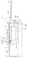
まず、本実施形態のレーザ処理装置の全体構成について図1を用いて説明する。図1は本実施形態のレーザ処理装置の全体構成を示す概略図である。
図示するように、本実施形態のレーザ処理装置は、レーザ照射処理が行われる処理室2と、処理室2内にガスを給気する給気ライン3と、処理室2内からガスを排気する排気ライン4とを有している。給気ライン3の下流端は、処理室2に接続されている。また、排気ライン4の上流端は、処理室2に接続されている。さらに、排気ライン4は、上流側の分岐点4aで互いに並列した小容量排気ライン4bと大容量排気ライン4cとに分岐し、下流側の合流点4dで小容量排気ライン4bと大容量排気ライン4cとが共通排気ライン4eに合流した構成を有している。大容量排気ライン4cは、例えば、小容量排気ライン4bと比較して大流量で排気可能な大径のものである。小容量排気ライン4bおよび大容量排気ライン4cは、本発明の排気ラインを構成する。
Hereinafter, the laser processing apparatus of one Embodiment of this invention is demonstrated based on FIGS. 1-3.
First, the overall configuration of the laser processing apparatus of this embodiment will be described with reference to FIG. FIG. 1 is a schematic view showing the overall configuration of the laser processing apparatus of this embodiment.
As shown in the figure, the laser processing apparatus of the present embodiment exhausts gas from the
処理室2には、デジタル差圧計5が設けられている。デジタル差圧計5は、処理室2内の圧力とレーザ処理装置が設置される場所、例えばクリーンルーム(図示しない)内の圧力との差圧を測定するものであり、本発明の処理室圧力測定部に相当する。
A digital
給気ライン3には、マスフローコントローラ(MFC)6が介設されている。マスフローコントローラ(MFC)6は、後述する制御部14により制御されて給気ライン3から処理室2内に給気されるガスの流量を調整するものであり、本発明の給気調整部に相当する。
A mass flow controller (MFC) 6 is interposed in the
小容量排気ライン4bには、上流側から下流側に順に、自動調整バルブ7および開閉バルブ8が介設されている。自動調整バルブ7は、後述する制御部14により制御されて小容量排気ライン4bから排気されるガスの流量を調整するものであり、本発明の処理側排気調整部に相当する。
また、大容量排気ライン4cには、開閉バルブ9が介設されている。
The small
An open / close valve 9 is interposed in the large
また、共通排気ライン4eには、デジタル差圧計10が設けられている。デジタル差圧計10は、共通排気ライン4e内の圧力とレーザ処理装置が設置される場所、例えばクリーンルーム(図示しない)内の圧力との差圧を測定するものであり、本発明の排気圧力測定部に相当する。
また、共通排気ライン4eのデジタル差圧計10の下流側には、自動調整バルブ11が介設されている。自動調整バルブ11は、後述する制御部14により制御されて共通排気ライン4eから排気されるガスの流量を調整するものであり、本発明の下流側排気調整部に相当する。
A digital
Further, an automatic adjustment valve 11 is interposed downstream of the digital
共通排気ライン4eの下流端は、レーザ処理装置が設置される工場などの施設側排気系統の共有排気ライン12に接続されている。自動調整バルブ11の下流側に位置する共通排気ライン4eの共有排気ライン12との接続端側には、デジタル差圧計13が設けられている。デジタル差圧計13は、共有排気ライン12との接続端側における共通排気ライン4e内の圧力とレーザ処理装置が設置される場所、例えばクリーンルーム(図示しない)内の圧力との差圧を測定するものであり、本発明の共有排気側圧力測定部に相当する。
The downstream end of the
上記デジタル差圧計5、10、13には、制御部14が接続されており、デジタル差圧計5、10、13の測定結果が制御部14に送信される。また、マスフローコントローラ(MFC)6、および自動調整バルブ7、11には、これらを制御可能な制御部14が接続されている。制御部14は、デジタル差圧計5の測定結果に基づきマスフローコントローラ(MFC)6および自動調整バルブ7の一方または両方を制御し、デジタル差圧計10の測定結果に基づき自動調整バルブ11を制御するものである。さらに、制御部14は、デジタル差圧計13の測定結果に基づき、該デジタル差圧計13により測定される圧力変動が所定の閾値を超えた場合に、処理室2におけるレーザ照射処理を中止する制御を行うものである。
制御部14は、CPUおよびこれを動作させるプログラム、該プログラムを格納したROM、作業エリアとなるRAM、マスフローコントローラ(MFC)6、自動調整バルブ7、11などの動作を制御する制御パラメータなどを格納した不揮発メモリなどによって構成されている。
A
The
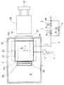
次に、本実施形態のレーザ処理装置の処理室2およびその周辺の具体的構成について図2および図3を用いて説明する。図2および図3はそれぞれ処理室2およびその周辺を示す正面断面図および平面断面図である。
図示するように、本実施形態のレーザ処理装置は、該処理室2外に設置されたレーザ発振器15と、該レーザ発振器15から出力されたレーザ光15aを整形して前記処理室2に導く光学系16とを備えている。また、処理室2には、光学系16の一部としてレーザ光15aを処理室2外部から処理室2内に導く導入窓17を有しており、導入窓17を通して導かれるレーザ光15aは、処理室2内に設けたシールドボックス18に設けた透過孔18aを通して被処理体100に照射される。シールドボックス18は、被処理体100の照射部分にシールドガスを吹き付けるものである。
被処理体100は、例えば、非晶質半導体膜であるアモルファスシリコン膜が成膜されたガラス基板である。この場合、アモルファスシリコン膜は、レーザ照射処理により結晶質半導体膜であるポリシリコン膜に結晶化される。
Next, a specific configuration of the
As shown in the figure, the laser processing apparatus of the present embodiment includes a
The
処理室2の側壁2aには、装入口19が設けられており、該装入口19の開閉を行うゲートバルブ20が備えられている。装入口19が位置する側で処理室2の外部に搬送ロボット21が位置する。なお、この例では、ゲートバルブ20を処理室2の側壁側に設けたが、図2示で正面側に設けるなどの構成も可能である。
An
処理室2内には、図3示で左右方向および上下方向に移動可能なステージ22が設置されており、該ステージ22は、移動装置23によって移動される。ステージ22は、平面矩形形状を有しており、シールドボックス18よりも装入口19側に待機位置を有している。
待機位置にあるステージ22の両側端縁上には、側面仕切壁24、24がステージ22の上面側縁に沿いつつ処理室2の天板2bに上端を固定されて垂下され、側面仕切壁24、24の下端面とステージ22の上面とは小隙間のみを有しており、天板2bと側面仕切壁24とは隙間なく固定されている。
なお、この形態では、ステージ22が幅方向に移動するため、側面仕切壁24、24の下端面とステージ22の上面との間の隙間は、ステージ22上に載置した被処理体100が通過できる大きさに形成されている。なお、ステージ22を幅方向に移動させない場合には、該隙間をより狭いものにして気密性を高めることができる。
A
On both side edges of the
In this embodiment, since the
また、側面仕切壁24、24には、装入口19側においてステージ22の図2示右方側(以降後方側という)の後方端からステージ22の後方面に沿って下方に伸長する後方側面仕切壁24a、24aが連なっており、該後方側面仕切壁24a、24aは、装入口19側で側壁2aに隙間なく固定されている。また、後方側面仕切壁24a、24aの両下端同士は、装入口19の下方側で横板状の下方仕切壁24bで連結されている。後方側面仕切壁24a、24aの後方端部は、側壁2aに隙間なく固定されており、前方端部は、ステージ22の後方面に僅かに隙間を有して位置している。これにより装入口19の周囲が後方側面仕切壁24a、24a、下方仕切壁24bによって囲まれる。
Further, the
さらに、側面仕切壁24、24のシールドボックス18側(以降前方側という)の端部は、待機位置にあるステージ22の前方端側にまで伸長しており、側面仕切壁24、24の先端部間には、縦板状の前方仕切壁24cが連結されている。前方仕切壁24cの上端は天板2bに隙間なく固定されており、前方仕切壁24cの下端は、ステージ22に載置された被処理体100が通過できるようにステージ22上面との間に隙間を有して位置している。
上記側面仕切壁24、24、後方側面仕切壁24a、24a、下方仕切壁24b、前方仕切壁24cによって仕切壁が構成されている。該仕切壁は、酸素などによる汚染を受けにくい材質が望ましく、例えばアルマイト処理されたアルミニウム板を用いることができる。
Furthermore, the end of the
The
また、待機位置にあるステージ22、上記仕切壁、側壁2a、天板2bで囲まれる空間がロードロックエリアAとなっている。ロードロックエリアAは、前記したように仕切壁とステージ22との間に僅かな隙間を有する状態でシールドがなされている。
また、ロードロックエリアAとは別に、シールドボックス18が位置する空間がレーザ光照射エリアBに区画されている。
なお、上記では仕切壁は固定物として説明したが、仕切壁を可動のものや可変形状のものによって構成することも可能である。
処理室2のレーザ光照射エリアB側には、上記デジタル差圧計5が設置されている。デジタル差圧計5は、レーザ光照射エリアBの圧力とレーザ処理装置が設置された場所の圧力との差圧を測定するようになっている。なお、デジタル差圧計5は、処理室2のロードロックエリアA側に設置し、ロードロックエリアAの圧力とレーザ処理装置が設置された場所の圧力との差圧を測定するようにしてもよい。また、単一のデジタル差圧計5を設置することに代えて、処理室2のレーザ光照射エリアB側およびロードロックエリアA側のそれぞれにデジタル差圧計を設置してもよい。
A space surrounded by the
In addition to the load lock area A, a space in which the
In the above description, the partition wall is described as a fixed object. However, the partition wall may be configured by a movable or variable shape.
On the laser beam irradiation area B side of the
さらに、ロードロックエリアAには、上記給気ライン3および排気ライン4が接続されている。ロードロックエリアAは、給気ライン3からガスが給気され、排気ライン4からガスが排気されるようになっている。レーザ光照射エリアBも、ロードロックエリアAを介して、給気ライン3からガスが給気され、排気ライン4からガスが排気されるようになっている。
給気ライン3からロードロックエリアAに雰囲気ガスを給気することで、上記した仕切壁とステージ22との間の僅かな隙間からガスが外側に向けて吹き出されることでガスカーテンとしての機能が得られ、シールド性が向上する。したがって、仕切壁とステージ22との隙間は、ステージの移動を損なわない程度に極力小さくするのが望ましく、また、雰囲気ガスの給気によるガスカーテンの作用が十分に得られる程度に小さくすることが望ましい。
Further, the
By supplying atmospheric gas from the
次に、上記図1〜図3に示すレーザ処理装置の動作について説明する。
先ず、処理に先立ってステージ22を待機位置に移動させてゲートバルブ20を閉めておく。この状態で、以下のようにして処理室2に対して排気ライン4からの排気および給気ライン3からの給気を行い、処理室2内の処理雰囲気を調整する。なお、処理室2に対する給排気が開始されると、デジタル差圧計5、10、13は、それぞれ差圧の測定を開始し、該測定結果を制御部14に送信する。デジタル差圧計5、10、13による差圧の測定および測定結果の送信は、例えば、連続的に行われてもよいし、所定の時間間隔で断続的に行われてもよい。
Next, the operation of the laser processing apparatus shown in FIGS. 1 to 3 will be described.
First, prior to processing, the
まず、処理室2が所定の圧力に減圧されるまでは、開閉バルブ9および自動調整バルブ11を開放し、開閉バルブ8を閉止した状態で、大容量排気ライン4cを通して処理室2内のガスを排気する。
処理室2内が所定の圧力に減圧された後、開閉バルブ9を閉止し、開閉バルブ8を開放する。さらに、小容量排気ライン4bを通して処理室2内のガスを排気するとともに、給気ライン3を通して処理室2内に窒素ガス、アルゴンガスなどの不活性ガスを給気して、アイドリング状態とする。このようにレーザ照射が行われていないアイドリング状態において、制御部14は、デジタル差圧計5の測定結果に基づき、自動調整バルブ7を制御して排気ライン4から排気されるガスの流量を調整するともに、マスフローコントローラ(MFC)6を制御して給気ライン3から給気されるガスの流量を調整する。例えば、アイドリング状態では、給気ライン3から給気されるガスの流量を100L/minに設定するとともに、自動調整バルブ7を制御して、デジタル差圧計5により測定される差圧が所定の範囲内になるようにする。
さらに、制御部14は、デジタル差圧計10の測定結果に基づき、自動調整バルブ11を制御して、デジタル差圧計10によって測定される差圧が所定の圧力となるように共通排気ライン4eから排気されるガスの流量を調整する。
こうして、アイドリング状態では処理室2内におけるロードロックエリアAおよびレーザ光照射エリアBの処理雰囲気を、所定の圧力および所定の低酸素濃度に調整する。
なお、アイドリング状態は、レーザ照射時以外であって、ステージ22の移動時(レーザ照射時を除く)、被処理体100を入れ替える際のゲートバルブ20の開閉時、ゲートバルブ20の閉時の被処理体100の搬入待機時などの状態を意味する。
First, until the
After the inside of the
Further, the
Thus, in the idling state, the processing atmosphere in the load lock area A and the laser light irradiation area B in the
Note that the idling state is not during laser irradiation, but when the
なお、本実施形態では、ロードロックエリアAに給気ライン3および排気ライン4が接続されているが、さらにレーザ光照射エリアBに給気ラインと排気ラインとを接続して、これら給排気ラインからのガスの給排気をも行い、処理室2内の処理雰囲気を調整するようにしてもよい。また、ロードロックエリアAに接続された給排気ラインおよびレーザ光照射エリアBに接続された給排気ラインのいずれか1組による給排気により、処理室2内の処理雰囲気を調整するようにしてもよい。
In the present embodiment, the
被処理体100に対するレーザ照射処理を行う際には、アイドリング状態にあるレーザ処理装置において、ゲートバルブ20を開け、搬送ロボット21によって被処理体100を装入口19からロードロックエリアA内に装入し、ステージ22上に載置する。この際、上記と同様に、制御部14は、デジタル差圧計5の測定結果に基づき、自動調整バルブ7を制御して小容量排気ライン4bから排気されるガスの流量を調整するともに、マスフローコントローラ(MFC)6を制御して給気ライン3から給気されるガスの流量を調整する。さらに、制御部14は、デジタル差圧計10の測定結果に基づき、自動調整バルブ11を制御して共通排気ライン4eから排気されるガスの流量を調整する。
こうして、処理室2のロードロックエリアA内に被処理体100を装入する際に、給排気されるガスの流量を調整することにより、処理室2内の処理雰囲気の圧力、酸素濃度などの状態の変動を抑制することができる。
When performing laser irradiation processing on the object to be processed 100, the
Thus, when the
被処理体100をロードロックエリアAに装入した後、ゲートバルブ20を閉め、給気ライン3による給気と、排気ライン4による排気とを行って、処理室2内の処理雰囲気を安定化させる。上記のように、被処理体100を装入する際に処理室2内の処理雰囲気の状態の変動が抑制されているため、処理室2内の処理雰囲気を短時間で安定化することができる。
After the object to be processed 100 is inserted into the load lock area A, the
処理雰囲気の安定化後、ステージ22を移動装置23によって図2示左方に移動させる。この移動の途中で被処理体100の一部が照射位置に達するので、被処理体100が完全にレーザ光照射エリアBに移動する前にレーザ光の照射を開始することができる。
レーザ照射処理時には、例えば、給気ライン3から給気されるガスの流量を50L/minに設定するとともに、自動調整バルブ7を調整して、デジタル差圧計5により測定される差圧が所定の範囲内になるように制御し、アイドリング状態から脱する。
レーザ照射処理時に、レーザ光15aはレーザ発振器15から出力され、光学系16および光学系16内の導入窓17、さらに処理室2内のシールドボックス18を通して、透過孔18aからレーザ光照射エリアB内に位置する被処理体100に照射される。ステージ22は、移動装置23によって前後方向に移動することでレーザ光15aが走査される。走査の際には、ステージ22はロードロックエリアA側へ一部が位置するように移動可能になっており、ロードロックエリアA側の空間が利用される。
また、ステージ22を左右方向で移動させて走査位置を変更することで、被処理体100の全面に亘ってレーザ光照射による処理を行うことができる。該処理において、仕切壁はステージ22および被処理体100の移動に支障となることはない。
After stabilizing the processing atmosphere, the
During the laser irradiation process, for example, the flow rate of the gas supplied from the
During the laser irradiation process, the
Further, by moving the
上記のように処理室2内において被処理体100を移動する際、および被処理体100に対してレーザ照射処理を行う際においても、制御部14は、デジタル差圧計5の測定結果に基づき、自動調整バルブ7を制御して小容量排気ライン4bから排気されるガスの流量を調整するともに、マスフローコントローラ(MFC)6を制御して給気ライン3から給気されるガスの流量を調整する。さらに、制御部14は、デジタル差圧計10の測定結果に基づき、自動調整バルブ11を制御して共通排気ライン4eから排気されるガスの流量を調整する。
こうして、アイドリング状態およびレーザ照射処理時に、処理室2内において被処理体100を移動する際およびレーザ照射処理を行う際において、給排気されるガスの流量を調整することにより、処理室2内の処理雰囲気を安定した状態に維持することができる。これにより、安定化された処理雰囲気において、被処理体100の処理を高い品質で効率よく行うことができる。
As described above, when moving the object to be processed 100 in the
In this way, by adjusting the flow rate of gas supplied and exhausted when moving the
レーザ照射処理を終了すると、例えば、給気ライン3から給気されるガスの流量を100L/minに設定するとともに、自動調整バルブ7を調整して、デジタル差圧計5により測定される差圧が所定の範囲内になるように制御してアイドリング状態に移行する。処理が完了した被処理体100は、ステージ22とともに移動装置23によってロードロックエリアA側に移動させ、ゲートバルブ20を開け、搬送ロボット21によって処理室2外に搬出する。この際、上記と同様に、制御部14は、デジタル差圧計5の測定結果に基づき、自動調整バルブ7を制御して小容量排気ライン4bから排気されるガスの流量を調整するともに、マスフローコントローラ(MFC)6を制御して給気ライン3から給気されるガスの流量を調整する。さらに、制御部14は、デジタル差圧計10の測定結果に基づき、自動調整バルブ11を制御して共通排気ライン4eから排気されるガスの流量を調整する。
こうして、処理室2のロードロックエリアA側に被処理体100を移動する際、および被処理体100を処理室2外に搬出する際に、給排気されるガスの流量を調整することにより、処理室2内の処理雰囲気の圧力、酸素濃度などの状態の変動を抑制することができる。
When the laser irradiation process is finished, for example, the flow rate of the gas supplied from the
In this way, by adjusting the flow rate of gas supplied and exhausted when moving the
以後、前記と同様に他の被処理体100を搬入して同様の処理を行うことができる。上記のように、処理が完了した被処理体100を処理室2外に搬出する際には、処理室2内の処理雰囲気の状態の変動が抑制されているため、処理室2内の処理雰囲気の調整を短時間で行うことができる。したがって、他の被処理体100の処理を短時間で開始することができる。
Thereafter, similar processing can be performed by loading another
また、上記のようにレーザ処理装置が動作している間、制御部14は、デジタル差圧計13により、共有排気ライン12との接続端側における共通排気ライン4e内の圧力の変動を常時監視する。常時監視において、制御部14は、デジタル差圧計13により測定された共有排気ライン12との接続端側における共通排気ライン4e内の圧力の変動が所定の閾値を超えると、処理室2内におけるレーザ照射処理を中止する制御を行う。レーザ照射処理は、レーザ発振器15から出力されたレーザ光15aをシャッタ(不図示)により遮断するなどして中止される。レーザ照射処理を中止する制御を行う基準となる圧力変動の閾値については、処理室2内の圧力がレーザ照射処理に不適となる圧力の変動をデジタル差圧計13により予め測定しておき、該測定値を閾値として用いることができる。ただし、閾値の設定がこれに限定されるものではない。こうして、共有排気ライン12との接続端側における共通排気ライン4e内の圧力の変動に応じてレーザ照射処理を中止する制御を行うことにより、レーザ照射処理における不良発生率を確実に低減することができる。
While the laser processing apparatus is operating as described above, the
なお、上記実施形態では、仕切壁などによりロードロックエリアAが画定されていたが、該仕切壁の構成は上記実施形態の構成に限定されるものではなく、種々の構成とすることができる。また、ロードロックエリアAは、必ずしも設けられていなくてもよい。
また、上記実施形態では、デジタル差圧計5、10、13により各部の差圧を測定するものについて説明したが、これらデジタル差圧計に代えて、種々の圧力測定手段を用いることができる。
In the above embodiment, the load lock area A is defined by a partition wall or the like. However, the configuration of the partition wall is not limited to the configuration of the above embodiment, and may be various configurations. Further, the load lock area A is not necessarily provided.
Moreover, although the said embodiment demonstrated what measures the differential pressure | voltage of each part by the digital
以上、本発明について上記実施形態に基づいて説明を行ったが、本発明は上記実施形態の内容に限定されるものではなく、適宜の変更が可能である。 As mentioned above, although this invention was demonstrated based on the said embodiment, this invention is not limited to the content of the said embodiment, A suitable change is possible.
2 処理室
3 給気ライン
4 排気ライン
4b 小容量排気ライン
4c 大容量排気ライン
4e 共通排気ライン
5 デジタル差圧計
6 マスフローコントローラ(MFC)
7 自動調整バルブ
10 デジタル差圧計
11 自動調整バルブ
12 共有排気ライン
13 デジタル差圧計
14 制御部
15 レーザ発振器
15a レーザ光
100 被処理体
A ロードロックエリア
B レーザ光照射エリア
2 Processing
7
Claims (5)
前記処理室内にガスを給気する給気ラインと、
前記給気ラインにおける前記給気を調整する給気調整部と、
前記処理室内からガスを排気する排気ラインと、
前記排気ラインにおける前記排気を調整する処理側排気調整部と、
前記処理室内の圧力を測定する処理室圧力測定部と、
前記処理側排気調整部の下流側における前記排気ライン内の圧力を測定する排気圧力測定部と、
前記排気圧力測定部による測定位置の下流側で前記排気ラインの排気を調整する下流側排気調整部と、を有し、
前記排気圧力測定部の測定結果を受け、該測定結果に基づき、前記下流側排気調整部を制御して、前記処理側排気調整部と前記下流側排気調整部との間の前記排気ライン内の圧力を所定の圧力に調整し、前記処理室圧力測定部の測定結果を受け、該測定結果に基づき、前記給気調整部および前記処理側排気調整部の一方または両方を制御して、前記処理室内の圧力を所定の圧力に調整する制御部と、を有することを特徴とするレーザ処理装置。 A processing chamber in which an object to be processed is accommodated and a laser irradiation process is performed on the object to be processed;
An air supply line for supplying gas into the processing chamber;
An air supply adjusting unit for adjusting the air supply in the air supply line;
An exhaust line for exhausting gas from the processing chamber;
A processing-side exhaust adjustment unit for adjusting the exhaust in the exhaust line;
A processing chamber pressure measuring unit for measuring the pressure in the processing chamber;
An exhaust pressure measurement unit for measuring the pressure in the exhaust line on the downstream side of the processing side exhaust adjustment unit;
A downstream side exhaust adjustment unit that adjusts exhaust of the exhaust line on the downstream side of the measurement position by the exhaust pressure measurement unit,
The measurement result of the exhaust pressure measurement unit is received, and based on the measurement result, the downstream side exhaust adjustment unit is controlled, and the inside of the exhaust line between the processing side exhaust adjustment unit and the downstream side exhaust adjustment unit is controlled. The pressure is adjusted to a predetermined pressure, the measurement result of the processing chamber pressure measurement unit is received, and one or both of the air supply adjustment unit and the processing side exhaust adjustment unit are controlled based on the measurement result, and the processing And a control unit that adjusts the indoor pressure to a predetermined pressure .
前記処理室内にガスを給気する給気ラインと、 An air supply line for supplying gas into the processing chamber;
前記給気ラインにおける前記給気を調整する給気調整部と、 An air supply adjusting unit for adjusting the air supply in the air supply line;
前記処理室内からガスを排気する排気ラインと、 An exhaust line for exhausting gas from the processing chamber;
前記排気ラインにおける前記排気を調整する処理側排気調整部と、 A processing-side exhaust adjustment unit for adjusting the exhaust in the exhaust line;
前記処理室内の圧力を測定する処理室圧力測定部と、 A processing chamber pressure measuring unit for measuring the pressure in the processing chamber;
前記処理室圧力測定部の測定結果を受け、該測定結果に基づき、前記給気調整部および前記処理側排気調整部の一方または両方を制御して、前記処理室内の圧力を調整する制御部と、 A control unit that receives the measurement result of the processing chamber pressure measurement unit and controls one or both of the air supply adjustment unit and the processing side exhaust adjustment unit based on the measurement result, and adjusts the pressure in the processing chamber; ,
前記処理室内で移動可能で、前記被処理体が設置されて該被処理体に対し前記レーザ処理が行われるステージと、を有し、 A stage that is movable in the processing chamber and in which the object to be processed is installed and the laser processing is performed on the object to be processed;
前記処理室に、ロードロックエリアとレーザ照射エリアとを有し、前記ステージは、前記移動に伴って、一時的に前記ロードロックエリアの一部の仕切壁を構成することを特徴とするレーザ処理装置。 The processing chamber has a load lock area and a laser irradiation area, and the stage temporarily constitutes a part of the partition wall of the load lock area with the movement. apparatus.
前記制御部は、前記排気圧力測定部の測定結果を受け、該測定結果に基づき、前記下流側排気調整部を制御して、前記処理側排気調整部と前記下流側排気調整部との間の前記排気ライン内の圧力を調整することを特徴とする請求項2に記載のレーザ処理装置。 An exhaust pressure measuring unit that measures the pressure in the exhaust line on the downstream side of the processing side exhaust adjusting unit, and a downstream exhaust adjusting unit that adjusts the exhaust gas on the downstream side of the measurement position by the exhaust pressure measuring unit And having
The control unit receives the measurement result of the exhaust pressure measurement unit, and controls the downstream side exhaust adjustment unit based on the measurement result, and between the processing side exhaust adjustment unit and the downstream side exhaust adjustment unit. The laser processing apparatus according to claim 2 , wherein a pressure in the exhaust line is adjusted.
前記共有排気ラインとの接続端側における前記排気ライン内の圧力を測定する共有排気側圧力測定部を有し、
前記制御部は、前記共有排気側圧力測定部の測定結果を受け、測定された前記排気ライン内の圧力の変動が所定の閾値を超えたときに前記レーザ照射処理を中止する制御を行うことを特徴とする請求項1〜4のいずれかに記載のレーザ処理装置。 The exhaust line is connected to a common exhaust line of the facility side exhaust system ;
A shared exhaust side pressure measuring unit for measuring the pressure in the exhaust line on the connection end side with the shared exhaust line;
The control unit receives the measurement result of the shared exhaust side pressure measurement unit, and performs control to stop the laser irradiation processing when the measured pressure fluctuation in the exhaust line exceeds a predetermined threshold value. The laser processing apparatus according to claim 1, wherein the apparatus is a laser processing apparatus.
Priority Applications (1)
| Application Number | Priority Date | Filing Date | Title |
|---|---|---|---|
| JP2011226781A JP5774439B2 (en) | 2011-10-14 | 2011-10-14 | Laser processing equipment |
Applications Claiming Priority (1)
| Application Number | Priority Date | Filing Date | Title |
|---|---|---|---|
| JP2011226781A JP5774439B2 (en) | 2011-10-14 | 2011-10-14 | Laser processing equipment |
Publications (2)
| Publication Number | Publication Date |
|---|---|
| JP2013089671A JP2013089671A (en) | 2013-05-13 |
| JP5774439B2 true JP5774439B2 (en) | 2015-09-09 |
Family
ID=48533315
Family Applications (1)
| Application Number | Title | Priority Date | Filing Date |
|---|---|---|---|
| JP2011226781A Active JP5774439B2 (en) | 2011-10-14 | 2011-10-14 | Laser processing equipment |
Country Status (1)
| Country | Link |
|---|---|
| JP (1) | JP5774439B2 (en) |
Family Cites Families (9)
| Publication number | Priority date | Publication date | Assignee | Title |
|---|---|---|---|---|
| JP2588864B2 (en) * | 1989-03-31 | 1997-03-12 | ウシオ電機株式会社 | Light processing equipment |
| JPH1197382A (en) * | 1997-09-19 | 1999-04-09 | Japan Steel Works Ltd:The | Laser annealer |
| JP3204188B2 (en) * | 1997-12-09 | 2001-09-04 | 日本電気株式会社 | Method for forming silicon thin film and apparatus for forming silicon thin film |
| JP4845267B2 (en) * | 2001-01-15 | 2011-12-28 | 東芝モバイルディスプレイ株式会社 | Laser annealing apparatus and laser annealing method |
| JP3955592B2 (en) * | 2004-11-19 | 2007-08-08 | 住友重機械工業株式会社 | Processing apparatus and processing method |
| JP2007127032A (en) * | 2005-11-02 | 2007-05-24 | Sumitomo Heavy Ind Ltd | Decompression processing device |
| JP4959457B2 (en) * | 2007-07-26 | 2012-06-20 | 東京エレクトロン株式会社 | Substrate transport module and substrate processing system |
| JP2010141079A (en) * | 2008-12-11 | 2010-06-24 | Hitachi Kokusai Electric Inc | Method of manufacturing semiconductor device |
| JP5495847B2 (en) * | 2010-02-24 | 2014-05-21 | 株式会社日立国際電気 | Semiconductor device manufacturing method, substrate processing apparatus, and substrate processing method |
-
2011
- 2011-10-14 JP JP2011226781A patent/JP5774439B2/en active Active
Also Published As
| Publication number | Publication date |
|---|---|
| JP2013089671A (en) | 2013-05-13 |
Similar Documents
| Publication | Publication Date | Title |
|---|---|---|
| US5529630A (en) | Apparatus for manufacturing a liquid crystal display substrate, and apparatus for evaluating semiconductor crystals | |
| KR102337428B1 (en) | Laser annealing device, serial conveyance path for laser annealing, laser beam radiation means, and laser annealing method | |
| KR102287466B1 (en) | Substrate processing apparatus, semiconductor device manufacturing method and program | |
| KR101615280B1 (en) | Heat treatment system, heat treatment method, and computer-readable recording medium having a program | |
| JP6944990B2 (en) | Substrate processing equipment, semiconductor equipment manufacturing methods and programs | |
| JP6215281B2 (en) | SUBSTRATE TRANSFER DEVICE, SEMICONDUCTOR MANUFACTURING DEVICE, AND SUBSTRATE TRANSFER METHOD | |
| US10096499B2 (en) | Substrate processing method, program, control apparatus, film forming apparatus, and substrate processing system | |
| JP5408678B2 (en) | Laser processing equipment | |
| JP4130790B2 (en) | Laser processing machine | |
| US20190326140A1 (en) | Laser processing apparatus and laser processing method | |
| KR20110071591A (en) | Laser processing apparatus which can control size of laser beam | |
| US9418866B2 (en) | Gas treatment method | |
| JP5774439B2 (en) | Laser processing equipment | |
| KR101403459B1 (en) | Apparatus for thermal laser process | |
| KR101183511B1 (en) | Laser processing apparatus | |
| TWI471914B (en) | Laser treatment apparatus | |
| TWI743152B (en) | Heat treatment apparatus and heat treatment method | |
| JP5467578B2 (en) | Laser processing equipment | |
| KR100278977B1 (en) | Laser equipment | |
| JP4748594B2 (en) | Vacuum processing apparatus and vacuum processing method | |
| JP5447991B2 (en) | Laser processing equipment | |
| JP2696570B2 (en) | Vertical heat treatment equipment | |
| WO2009145030A1 (en) | Semiconductor processing device | |
| JPH10294289A (en) | Laser annealing device and its control method | |
| JP2009013462A (en) | Substrate treatment device |
Legal Events
| Date | Code | Title | Description |
|---|---|---|---|
| A621 | Written request for application examination |
Free format text: JAPANESE INTERMEDIATE CODE: A621 Effective date: 20131219 |
|
| A977 | Report on retrieval |
Free format text: JAPANESE INTERMEDIATE CODE: A971007 Effective date: 20140811 |
|
| A131 | Notification of reasons for refusal |
Free format text: JAPANESE INTERMEDIATE CODE: A131 Effective date: 20140910 |
|
| A521 | Request for written amendment filed |
Free format text: JAPANESE INTERMEDIATE CODE: A523 Effective date: 20141106 |
|
| TRDD | Decision of grant or rejection written | ||
| A01 | Written decision to grant a patent or to grant a registration (utility model) |
Free format text: JAPANESE INTERMEDIATE CODE: A01 Effective date: 20150603 |
|
| A61 | First payment of annual fees (during grant procedure) |
Free format text: JAPANESE INTERMEDIATE CODE: A61 Effective date: 20150701 |
|
| R150 | Certificate of patent or registration of utility model |
Ref document number: 5774439 Country of ref document: JP Free format text: JAPANESE INTERMEDIATE CODE: R150 |
|
| R250 | Receipt of annual fees |
Free format text: JAPANESE INTERMEDIATE CODE: R250 |
|
| R250 | Receipt of annual fees |
Free format text: JAPANESE INTERMEDIATE CODE: R250 |
|
| R250 | Receipt of annual fees |
Free format text: JAPANESE INTERMEDIATE CODE: R250 |
|
| S111 | Request for change of ownership or part of ownership |
Free format text: JAPANESE INTERMEDIATE CODE: R313111 |
|
| R350 | Written notification of registration of transfer |
Free format text: JAPANESE INTERMEDIATE CODE: R350 |
|
| R250 | Receipt of annual fees |
Free format text: JAPANESE INTERMEDIATE CODE: R250 |
|
| R250 | Receipt of annual fees |
Free format text: JAPANESE INTERMEDIATE CODE: R250 |