JP5771997B2 - Projection apparatus, projection method, and program - Google Patents
Projection apparatus, projection method, and program Download PDFInfo
- Publication number
- JP5771997B2 JP5771997B2 JP2011003672A JP2011003672A JP5771997B2 JP 5771997 B2 JP5771997 B2 JP 5771997B2 JP 2011003672 A JP2011003672 A JP 2011003672A JP 2011003672 A JP2011003672 A JP 2011003672A JP 5771997 B2 JP5771997 B2 JP 5771997B2
- Authority
- JP
- Japan
- Prior art keywords
- projection
- unit
- light source
- brightness
- light
- Prior art date
- Legal status (The legal status is an assumption and is not a legal conclusion. Google has not performed a legal analysis and makes no representation as to the accuracy of the status listed.)
- Expired - Fee Related
Links
Images


Landscapes
- Projection Apparatus (AREA)
- Transforming Electric Information Into Light Information (AREA)
Description
本発明は、例えば電源容量が制限された電池駆動のプロジェクタ等に好適な投影装置、投影方法及びプログラムに関する。 The present invention relates to a projection apparatus, a projection method, and a program suitable for, for example, a battery-powered projector with a limited power supply capacity.
近時、レーザダイオード(以下「LD」と称する)等の半導体発光素子を光源に用いるプロジェクタが実用化されており、高輝度である点や色再現性が高い点、高圧放電灯などそれまでの放電管に比して消費電力や熱対策の点で有利であり、装置の小型化がより容易となるなど、優れた点が多い。 Recently, projectors using a semiconductor light emitting element such as a laser diode (hereinafter referred to as “LD”) as a light source have been put into practical use, and have high brightness, high color reproducibility, high pressure discharge lamps, etc. It is advantageous in terms of power consumption and heat countermeasures compared to the discharge tube, and has many excellent points such as easier device miniaturization.
この種のプロジェクタでは、投影光が間違って人体、特に眼に入射するのを防止するべく、種々の安全対策が考えられている。(例えば、特許文献1) In this type of projector, various safety measures have been considered in order to prevent projection light from entering the human body, particularly the eyes. (For example, Patent Document 1)
光源に用いるレーザ光が、投影面に達する前に誤って人体に損傷を与えることを回避するための安全対策については、上記特許文献に記載された技術を含み、種々考えられている。 Various safety measures have been considered, including techniques described in the above-mentioned patent documents, for preventing laser light used for the light source from accidentally damaging the human body before reaching the projection plane.
一方、近年の半導体技術の発達によって、光源となる半導体発光素子は大出力化されており、より明るい画像の投影が可能となっている。しかしながら、半導体発光素子の大出力化と引換えに半導体発光素子からの発熱量も増大し、この種の光源に対して一般的に用いられる冷却用のファンも、より容量の大きなものが要求される傾向にある。 On the other hand, with the recent development of semiconductor technology, the semiconductor light-emitting element as a light source has been increased in output, and a brighter image can be projected. However, the amount of heat generated from the semiconductor light emitting element is increased in exchange for an increase in output of the semiconductor light emitting element, and a cooling fan generally used for this type of light source is required to have a larger capacity. There is a tendency.
そのため、特にプロジェクタを狭い投影環境内で使用する場合などには、短い投影距離により無駄に投影画像が明るくなると共に、冷却ファンの駆動音が騒音となり易いなど、上記安全対策以外にも要求される点は多い。 Therefore, especially when the projector is used in a narrow projection environment, the projected image becomes uselessly bright due to the short projection distance, and the driving sound of the cooling fan tends to be noisy. There are many points.
特に、電池を電源として使用する携帯型のプロジェクタでは、投影画質を確保した上で、容量に制限のある電池を有効に活用し、投影時間を一層長くすることが望まれている。 In particular, in a portable projector using a battery as a power source, it is desired that the projection time is further increased by effectively utilizing a battery having a limited capacity while ensuring the projection image quality.
本発明は上記のような実情に鑑みてなされたもので、その目的とするところは、適正な画質を確保すると共に、無駄な電力消費を極力抑制して運転することが可能な投影装置、投影方法及びプログラムを提供することにある。 The present invention has been made in view of the above-described circumstances, and an object of the present invention is to provide a projection apparatus and a projection that can be operated while ensuring appropriate image quality and suppressing wasteful power consumption as much as possible. It is to provide a method and a program.
本発明の一態様は、投影装置であって、光源と、上記光源からの光を用い、入力される画像信号に応じた光像を形成して投影する投影手段と、上記投影手段による投影面までの距離を測定する測定手段と、上記測定手段での測定結果に応じ、上記投影手段より出射する光像の明るさ調整を含む運転モードを可変設定する投影制御手段と、上記光源による駆動を開始する前後の投影面方向の明るさを検出する検出手段と、投影面における光像を合焦させる合焦手段と、上記合焦手段を用いた合焦操作を受け付ける受付手段とを具備し、上記投影制御手段は、上記受付手段による合焦操作に基づいて、上記光源を消灯させてから、上記検出手段によって上記光源による駆動を開始する前後の投影面方向の明るさを検出させ、上記測定手段での測定結果と、上記光源による駆動を開始する前後の投影面方向の明るさの差とに応じ、上記投影手段より出射する光像の明るさ調整を行なうことを特徴とする。 One embodiment of the present invention is a projection apparatus, which includes a light source, a projection unit that forms and projects a light image according to an input image signal using light from the light source, and a projection plane formed by the projection unit. Measurement means for measuring the distance to the projection, projection control means for variably setting the operation mode including brightness adjustment of the light image emitted from the projection means, and driving by the light source according to the measurement result of the measurement means. Detecting means for detecting brightness in the direction of the projection plane before and after the start, focusing means for focusing the optical image on the projection plane, and receiving means for receiving a focusing operation using the focusing means , The projection control means turns off the light source based on the focusing operation by the receiving means, and then detects the brightness in the direction of the projection plane before and after starting the driving by the light source by the detection means, and measures the measurement. Measurement by means And fruit, according to the difference in brightness between before and after the projection plane direction to start driving by the light source, and performing brightness adjustment of the light image emitted from the projection unit.
本発明によれば、適正な画質を確保すると共に、無駄な電力消費を極力抑制して運転することが可能となる。 According to the present invention, it is possible to ensure proper image quality and to operate while suppressing wasteful power consumption as much as possible.
以下、本発明をDLP(Digital Light Processing)(登録商標)方式の電池駆動によるデータプロジェクタ装置に適用した場合の一実施形態について図面を参照して説明する。 Hereinafter, an embodiment in which the present invention is applied to a DLP (Digital Light Processing) (registered trademark) battery-driven data projector apparatus will be described with reference to the drawings.
図1は、本実施形態に係るデータプロジェクタ装置10の主として電子回路の機能構成を説明する図である。同図中、符号11は入力部である。この入力部11は、例えばピンジャック(RCA)タイプのビデオ入力端子、D−sub15タイプのRGB入力端子、HDMI(High−Definition Multimedia Interface)規格の画像/音声入力端子、及びUSB(Universal Serial Bus)コネクタを有し、これらのいずれかの端子を介して有線接続される外部機器から、画像信号及び音声信号を入力する。
FIG. 1 is a diagram for mainly explaining a functional configuration of an electronic circuit of the
入力部11から入力された各種規格の画像信号は、システムバスSBを介し、一般にスケーラとも称される投影画像変換部12に入力される。
The image signals of various standards input from the
投影画像変換部12は、入力される画像信号を投影に適した所定のフォーマットの画像信号に統一し、内蔵する表示用のバッファメモリに適宜書込んだ後に、書込んだ画像信号を読出して投影画像駆動部13へ送る。
The projection image conversion unit 12 unifies the input image signal into an image signal of a predetermined format suitable for projection, appropriately writes it in a built-in display buffer memory, and then reads and projects the written image signal. The image is sent to the
この際、OSD(On Screen Display)用の各種動作状態を示すシンボル等のデータも必要に応じて投影画像変換部12内のバッファメモリで画像信号に重畳加工し、加工後の画像信号を読出して投影画像駆動部13へ送る。
At this time, data such as symbols indicating various operation states for OSD (On Screen Display) is also superimposed on the image signal by the buffer memory in the projection image conversion unit 12 as necessary, and the processed image signal is read out. The image is sent to the projection
投影画像駆動部13は、送られてきた画像信号に応じて、所定のフォーマットに従ったフレームレート、例えば60[フレーム/秒]と色成分の分割数、及び表示階調数を乗算した、より高速な時分割駆動により、マイクロミラー素子14を表示駆動する。
The projection
このマイクロミラー素子14は、アレイ状に配列された複数、例えばWXGA(横1280画素×縦768画素)個の微小ミラーの各傾斜角度を個々に高速でオン/オフ動作して表示動作することで、その反射光により光像を形成する。
The
一方で、光源部15から時分割でR,G,Bの原色光が循環的に出射される。この光源部15からの原色光が、ミラー16で全反射して上記マイクロミラー素子14に照射される。
On the other hand, R, G, and B primary color lights are emitted cyclically from the
そして、マイクロミラー素子14での反射光で光像が形成され、形成された光像が投影レンズ部17を介して、投影対象となる図示しないスクリーンに投影表示される。
Then, an optical image is formed by the reflected light from the
上記投影レンズ部17は、内部のレンズ光学系中に、フォーカス位置を移動するためのフォーカスレンズ群及びズーム(投影)画角を可変するためのズームレンズ群を有し、それらのレンズ群は共にレンズモータ(M)18の回動により駆動される。レンズモータ18は、上記投影画像駆動部13からの駆動信号に基づいて駆動される。
The
上記光源部15は、緑色(G)光を発するLD(以下「G−LD」と称する)19、
赤色(R)光を発する発光ダイオード(以下「R−LED」と称する)20、及び青色(B)光を発するLD(以下「B−LD」と称する)21を有する。
The
It has a light emitting diode (hereinafter referred to as “R-LED”) 20 that emits red (R) light and an LD (hereinafter referred to as “B-LD”) 21 that emits blue (B) light.
G−LD19の発する緑色光は、ダイクロイックミラー22を透過した後に上記ミラー16へ送られる。
Green light emitted from the G-LD 19 is transmitted to the
R−LED20の発する赤色光は、ダイクロイックミラー23で反射された後、上記ダイクロイックミラー22でも反射されて上記ミラー16へ送られる。
The red light emitted from the R-
B−LD21の発する青色光は、ミラー24で反射された後に上記ダイクロイックミラー23を透過し、その後に上記ダイクロイックミラー22で反射されて上記ミラー16へ送られる。
上記ダイクロイックミラー22は、緑光を透過する一方で、赤色光及び青色光を反射する。上記ダイクロイックミラー23は、赤色光を反射する一方で、青色光を透過する。
The blue light emitted from the B-LD 21 is reflected by the
The
上記G−LD19、R−LED20、及びB−LD21を冷却するべく冷却ファン25が設けられる。この冷却ファン25は、ファンモータ(M)26により回転し、発生した冷却風を上記光源の素子19〜21に当てて熱交換させ、熱せられた空気をデータプロジェクタ装置10外部に排出させる。
A
しかして上記光源部15のG−LD19、R−LED20、及びB−LD21の各発光タイミングや駆動信号の波形等を投影光駆動部27が統括して制御する。投影光駆動部27は、上記投影画像駆動部13から与えられる画像信号に同期したタイミング信号と、後述するCPU33の制御に応じて上記G−LD19、R−LED20、及びB−LD21の発光動作を制御する他、ファンモータ26の回転により冷却ファン25で発生される冷却風の強度を制御する。
Accordingly, the projection
また、上記投影レンズ部17と隣接するようにして受光レンズ28を配設し、受光レンズ28の合焦位置に固体撮像素子である、例えばCMOSイメージセンサ29を配設する。
In addition, a
投影レンズ部17による投影範囲を含んで撮影可能なように上記受光レンズ28及びCMOSイメージセンサ29が設けられるもので、CMOSイメージセンサ29での撮影動作により得られた、投影範囲を含む画像信号はA/D変換器30でデジタル化された後、撮影制御部31に送られる。
The
この撮影制御部31は、上記CMOSイメージセンサ29を走査駆動して撮影動作を実行させる他、上記受光レンズ28の位置を移動させ、CMOSイメージセンサ29に入射される光像を合焦させるフォーカスレンズモータ32の駆動制御も行なう。
The
撮影制御部31は、CMOSイメージセンサ29での撮影により得た画像データを、このデータプロジェクタ装置10全体の制御動作を司るCPU33へ送出する。
The
上記各回路の動作すべてをCPU33が制御する。このCPU33は、メインメモリ34及びプログラムメモリ35と直接接続される。メインメモリ34は、例えばSRAMで構成され、CPU33のワークメモリとして機能する。プログラムメモリ35は、電気的書換可能な不揮発性メモリ、例えばフラッシュROMで構成され、CPU33が実行する動作プログラムや各種定型データ、後述するテストチャートパターンの画像データやルックアップテーブル等を記憶する。
上記プログラムメモリ35が記憶する定型データ中には、上記G−LD19、R−LED20、及びB−LD21の各駆動電流値、冷却ファン25を回転させるファンモータ26の駆動電圧値等の駆動情報を含む。
The
The standard data stored in the
CPU33は、上記プログラムメモリ35に記憶されている動作プログラムや定型データ等を読出し、メインメモリ34に展開して記憶させた上で、当該プログラムを実行することにより、このデータプロジェクタ装置10を統括して制御する。
The
上記CPU33は、操作部36からのキー操作信号に応じて各種投影動作を実行する。
この操作部36は、このデータプロジェクタ装置10専用の図示しないリモートコントローラからの赤外線変調信号を受信するリモコン受光部と、データプロジェクタ装置10の例えば筐体上面に設けられるキー入力部を含む。操作部36は、ユーザがデータプロジェクタ装置10専用のリモートコントローラあるいは本体のキー入力部で操作したキーに基づくキー操作信号をCPU33へ出力する。
The
上記CPU33はさらに、上記システムバスSBを介して音声処理部37と接続される一方で、電源制御部38と直接接続される。
音声処理部37は、PCM音源等の音源回路を備え、投影動作時に与えられる音声信号をアナログ化し、スピーカ部39を駆動して放音させ、あるいは必要によりビープ音等を発生させる。
The
The
電源制御部38は、このデータプロジェクタ装置10の電源であるバッテリ40の充放電を管理し、さらにバッテリ40からの電力を必要な電圧値に変換、安定化した上で上記各回路に供給する。電源制御部38は、このバッテリ40の消耗状態を示す端子間電圧値を上記CPU33へ送出する。
The
次に上記実施形態の動作について説明する。
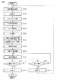
図2は、このデータプロジェクタ装置10の電源をオン(投入)した際に実行する初期設定動作とそれに続く投影動作の処理内容を示す。電源をオンした直後にCPU33は、まずデータプロジェクタ装置10の設置環境を把握するべく、CMOSイメージセンサ29により投影方向の明るさを測定させる(ステップS101)。
Next, the operation of the above embodiment will be described.
FIG. 2 shows the processing contents of the initial setting operation executed when the power of the
この場合、受光レンズ28とそのフォーカスレンズモータ32によるAF(自動合焦)動作は必要とせず、例えば受光レンズ28を予め設定された中間位置、例えば撮影距離が2[m]で合焦するような位置に固定した状態で投影方向を撮影させることにより、投影範囲のおおよその明るさを測定させる。
In this case, AF (automatic focusing) operation by the
次いでCPU33は、光源部15での発光動作を開始させた上で(ステップS102)、プログラムメモリ35からテストチャートパターンの画像データを読出し、その画像データに応じた投影を実行する(ステップS103)。
Next, the
この段階では、まだ投影面までの距離はわかっていないので、予め設定された中間位置、例えば投影距離が2[m]で合焦するような位置に投影レンズ部17のフォーカスレンズ位置を固定した状態で投影させる。
At this stage, since the distance to the projection surface is not yet known, the focus lens position of the
この投影状態から再度CMOSイメージセンサ29での撮影により投影方向の明るさを測定させた上で、CMOSイメージセンサ29における適正な露光(AE)条件を算出する(ステップS104)。
The brightness in the projection direction is measured again by photographing with the
次いで、上記算出したAE条件を設定し、CMOSイメージセンサ29から得られる画像のコントラスト値が最も高くなるように受光レンズ28をフォーカスレンズモータ32により移動させる、所謂コントラスト方式のAF動作を実行する。
Next, the calculated AE condition is set, and a so-called contrast AF operation is performed in which the
こうして得た合焦位置を基に、CPU33は投影レンズ部17のフォーカスレンズをレンズモータ18により駆動して、投影画像のAF動作を実行する(ステップS105)。
Based on the in-focus position thus obtained, the
次にCPU33は、プログラムメモリ35からルックアップテーブル(LUT)を読出してメインメモリ34に記憶させた後(ステップS106)、光源部15をオンする前に測定した投影方向の明るさLdkと、光源部15をオンした後に測定した投影方向の明るさLbr、及び上記AF動作により得た投影面までの距離とにより該テーブルを参照して、投影モードを選択する(ステップS107)。
Next, the
図3は、プログラムメモリ35から読出されるルックアップテーブルの構成例を示す。
ここでは、説明を簡易化するべく、可変設定される投影モードを全部で4段階あるものとした例を示す。
FIG. 3 shows a configuration example of a lookup table read from the
Here, in order to simplify the explanation, an example in which there are four stages of projection modes that are variably set is shown.
図3(A)は、各投影モードのモード名、光源(19〜21)の電流値、冷却ファン25の駆動強度、及び備考として光源部15における消費電力の概算値を示す。投影モードの番号の値が大きいほど、消費電力が大きくなると共に、画像をより明るく投影できる。
FIG. 3A shows the mode name of each projection mode, the current value of the light source (19 to 21), the driving intensity of the cooling
上記光源(19〜21)の電流値は、特性の異なるG−LD19、R−LED20、及びB−LD21共に一律な電流値を設定するものではなく、実際には個々の素子の個体差等もさらに勘案して個別に設定されるものとする。
The current values of the light sources (19 to 21) are not set to uniform current values for the G-
図3(B)は、光源部15をオンする前に測定した投影方向の明るさLdkと、光源部15をオンした後に測定した投影方向の明るさLbrとの差と、投影距離とにより投影モードを選択するルックアップを例示している。
FIG. 3B shows a projection based on the difference between the brightness Ldk in the projection direction measured before turning on the
ここでは、光源オン前の明るさLdkと、光源オン後の明るさLbrとの差が、予め設定されるしきい値Lth未満であるか、Lth以上であるかにより、データプロジェクタ装置10の設置環境が、例えば会議室でのプレゼンテーション等のように投影面にデータプロジェクタ装置10からの投影光以外の光が入射するような、ある程度明るい環境であるのか、あるいはデータプロジェクタ装置10の投光以外の光が存在しない暗室状態といった暗い環境であるのかを区別しており、その区別に応じて投影距離により上記図3(A)で示した投影モードを割り当てるものとしている。
Here, the installation of the
当然ながら、明るい環境下では暗い環境下に比して、より明るい画像を投影しないと画像の内容が判別し難いため、同じ投影距離でも選択する投影モードが異なり、より明るいものとしている。 As a matter of course, in a bright environment, it is difficult to discriminate the contents of an image unless a brighter image is projected, compared to a dark environment.
こうして投影モードを選択するとCPU33は、光源部15のG−LD19、R−LED20、及びB−LD21をそれぞれ選択した投影モードでの明るさとなるように投影光駆動部27で設定すると共に(ステップS108)、それら光源の素子(19〜21)を必要充分な風量で冷却させるべく、冷却ファン25用のファンモータ26を同じく選択した投影モードでのファン強度となるように投影光駆動部27で設定する(ステップS109)。
When the projection mode is selected in this way, the
以上で、設置環境に応じた投影モードの先端と設定を終えたものとしてCPU33は、以後、入力部11より入力される画像信号に応じた通常の投影処理を実行させながら(ステップS110)、併せてユーザが操作部36で電源をオフするキー操作をしたか否か(ステップS111)、再度の自動合焦を指示するべく「AF」キーを操作したか否か(ステップS112)を繰返し判断する。
As described above, assuming that the leading end and setting of the projection mode according to the installation environment have been completed, the
「AF」キーが操作されたと判断した場合、CPU33は上記ステップS112でそれを判断し、電源投入の初期設定と同じく、一旦光源部15での発光動作を停止させた後(ステップS113)、上記ステップS101に戻って、同様の処理を実行する。
If it is determined that the “AF” key has been operated, the
また、上記ステップS111でユーザが操作部36で電源をオフするキー操作をしたと判断した場合、CPU33はその時点で光源部15での発光動作を停止させた後(ステップS114)、以上でこの図2の処理を終了すると共に、装置の電源をオフ(切断)する。
If it is determined in step S111 that the user has performed a key operation to turn off the power using the
以上詳述した如く本実施形態によれば、投影環境に応じて適正な画質を確保すると共に、必要に応じて無駄な電力消費を極力抑制して運転することが可能となる。 As described above in detail, according to this embodiment, it is possible to ensure an appropriate image quality according to the projection environment and to operate while suppressing wasteful power consumption as much as possible.
特に本実施形態のように、投影面までの距離が近いほど、上記投影手段より出射する光像の明るさを下げることにより、特に投影面が近い場合に画像が明るすぎて明るい部分の詳細や暗い部分が視認しにくくなるのを回避できる。 In particular, as in this embodiment, the closer the distance to the projection surface is, the lower the brightness of the light image emitted from the projection means is. It can be avoided that the dark part becomes difficult to see.
この場合、上記実施形態では、光源となる素子の発光輝度を調整することで光像の明るさを下げるものとしたため、特に本データプロジェクタ装置10のようにバッテリ40を電源とした、使用電力量が制限される装置であっても、無駄な電力消費を回避しながら、合わせて見易さを考慮した画像の投影が実現できる。
In this case, in the above embodiment, since the brightness of the light image is lowered by adjusting the light emission luminance of the element serving as the light source, the power consumption using the
また上記実施形態では示さなかったが、光源となる素子の発光輝度は一定に保持しつつも、表示素子であるマイクロミラー素子14での階調(投影レンズ部17方向への反射時間)により明るさを下げるような調整も可能となる。この場合、光源となる素子の発光輝度を下げる場合程の省電力効果はないが、見易さを考慮した画像の投影が実現できることになる。
Although not shown in the above embodiment, the brightness of the light source element is kept constant, but the brightness is improved by the gradation (reflection time in the direction of the projection lens unit 17) at the
さらに上記実施形態では、光源部15で発光素子であるG−LD19、R−LED20、及びB−LD21を冷却するものとして冷却ファン25及びファンモータ26を設け、発光輝度と合わせて冷却能力も可変設定するものとしたので、無駄な電力消費を装置全体で回避すると共に、冷却ファン25による騒音の発生も必要最小限に抑制できる。
Furthermore, in the said embodiment, the cooling
加えて上記実施形態では、投影面において光像を合焦させる合焦手段を備えるものとしたので、測距用専用の部材を必要とせずに、投影面までの距離を測定できる。 In addition, in the above embodiment, since the focusing means for focusing the optical image on the projection surface is provided, the distance to the projection surface can be measured without requiring a dedicated member for distance measurement.
また上記実施形態において、投影面までの距離を測定する手段として、コントラスト方式の自動合焦機能を有する撮影部を備えるものとすれば、例えば携帯電話端末のカメラ機能やパーソナルコンピュータのWebカメラで用いられているカメラ機構部を流用することで、アクティブ・オートフォーカス方式のような測距用の部材を必要とせずに、投影面までの距離を比較的正確に測定できる。 Further, in the above embodiment, if a photographing unit having a contrast-type automatic focusing function is provided as a means for measuring the distance to the projection surface, for example, it is used in a camera function of a mobile phone terminal or a Web camera of a personal computer. By diverting the camera mechanism unit, the distance to the projection surface can be measured relatively accurately without the need for a distance measuring member such as the active autofocus method.
この点は、上記コントラスト方式と同様、位相差方式を採用することでも実現可能であり、撮像部を簡易な構成で実現できる。 This point can also be realized by adopting the phase difference method as in the contrast method, and the imaging unit can be realized with a simple configuration.
これらいずれのパッシブ・オートフォーカス方式であっても、上記実施形態のようにAF機能自体は光源をオンした明るい環境下で機能させることで、測距不能となってしまうことなく、確実に投影面までの距離を測定できる。 In any of these passive autofocus methods, the AF function itself functions in a bright environment with the light source turned on as in the above embodiment, so that the projection surface can be reliably obtained without becoming incapable of ranging. Can be measured.
さらに上記実施形態では、光源による駆動を開始する前後の明るさを検出してその差を勘案した上で測距結果と合わせて投影モードを選択するものとしたので、同一の距離であっても選択する投影モードを意図的に替えるなど、データプロジェクタ装置10を設置している環境に合わせてより細かく投影モードを設定することができる。
Furthermore, in the above embodiment, the brightness before and after the start of driving by the light source is detected and the difference is taken into account, and the projection mode is selected according to the distance measurement result. The projection mode can be set more finely according to the environment in which the
加えて上記実施形態では、合焦機能が呼び出される毎に、光源を消灯させてから、光源による駆動を開始する前後の投影面方向の明るさを検出させるようにしたので、設置状況が変わった可能性の高い場合に、自動で投影モードを設定することができる。 In addition, in the above embodiment, every time the focusing function is called, the light source is turned off, and the brightness in the projection plane direction before and after the start of driving by the light source is detected, so the installation situation has changed. When there is a high possibility, the projection mode can be automatically set.
なお、特に投影面までの距離が近く、投影画像の輝度を下げて投影を実行する場合には、投影画像に対して、例えば輪郭強調やカラー画像の彩度を向上させるなどの画像処理を施した上で投影することで、より見易い画像とすることができる。 It should be noted that, particularly when the distance to the projection surface is short and projection is performed with the brightness of the projection image lowered, image processing such as edge enhancement and color image saturation is applied to the projection image. In addition, it is possible to obtain an image that is easier to view by projecting the image.
また、上記実施形態は、自動で合焦させる自動合焦機能を適用した場合について説明したが、手動で合焦させ、合焦した位置情報から、投影面までの距離を算出するようにしてもよい。 Moreover, although the said embodiment demonstrated the case where the automatic focusing function to which it focuses automatically was applied, it may be made to calculate the distance to a projection surface from the focused position information manually and focusing. Good.
なお、上記実施形態は、電池駆動のDLP方式のデータプロジェクタ装置に適用した場合について説明したが、本発明は駆動電源やプロジェクタ方式等を限定するものではなく、その他の方式の投影装置、あるいは投影機能を備えた各種電子機器などにも同様に適用することが可能となる。 In addition, although the said embodiment demonstrated the case where it applied to the battery-driven DLP system data projector apparatus, this invention does not limit a drive power supply, a projector system, etc., The projection apparatus of another system, or projection The present invention can be similarly applied to various electronic devices having functions.
その他、本発明は上述した実施形態に限定されるものではなく、実施段階ではその要旨を逸脱しない範囲で種々に変形することが可能である。また、上述した実施形態で実行される機能は可能な限り適宜組み合わせて実施しても良い。上述した実施形態には種々の段階が含まれており、開示される複数の構成要件による適宜の組み合せにより種々の発明が抽出され得る。例えば、実施形態に示される全構成要件からいくつかの構成要件が削除されても、効果が得られるのであれば、この構成要件が削除された構成が発明として抽出され得る。 In addition, the present invention is not limited to the above-described embodiments, and various modifications can be made without departing from the scope of the invention in the implementation stage. Further, the functions executed in the above-described embodiments may be combined as appropriate as possible. The above-described embodiment includes various stages, and various inventions can be extracted by an appropriate combination of a plurality of disclosed constituent elements. For example, even if some constituent requirements are deleted from all the constituent requirements shown in the embodiment, if the effect is obtained, a configuration from which the constituent requirements are deleted can be extracted as an invention.
以下に、本願出願の当所の特許請求の範囲に記載された発明を付記する。 The invention described in the claims of the present application of the present application will be appended below.
請求項1記載の発明は、上記光源からの光を用い、入力される画像信号に応じた光像を形成して投影する投影手段と、上記投影手段による投影面までの距離を測定する測定手段と、上記測定手段での測定結果に応じ、上記投影手段より出射する光像の明るさ調整を含む運転モードを可変設定する投影制御手段とを具備したことを特徴とする。 According to a first aspect of the present invention, there is provided a projection unit that forms and projects a light image corresponding to an input image signal using light from the light source, and a measurement unit that measures the distance to the projection plane by the projection unit. And projection control means for variably setting an operation mode including brightness adjustment of a light image emitted from the projection means according to the measurement result of the measurement means.
請求項2記載の発明は、上記請求項1記載の発明において、上記投影制御手段は、上記測定手段で測定した投影面までの距離が近いほど、上記投影手段より出射する光像の明るさを下げることを特徴とする。 According to a second aspect of the present invention, in the first aspect of the present invention, the projection control means increases the brightness of the light image emitted from the projection means as the distance to the projection plane measured by the measurement means decreases. It is characterized by lowering.
請求項3記載の発明は、上記請求項2記載の発明において、上記投影制御手段は、上記光源での発光輝度を調整し、上記測定手段で測定した投影面までの距離が近いほど、上記投影手段より出射する光像の明るさを下げることを特徴とする。
The invention according to
請求項4記載の発明は、上記請求項2記載の発明において、上記投影制御手段は、上記測定手段で測定した投影面までの距離が近いほど、上記投影手段より出射する光像の階調調整により明るさを下げることを特徴とする。 According to a fourth aspect of the present invention, in the invention according to the second aspect, the projection control means adjusts the gradation of the light image emitted from the projection means as the distance to the projection surface measured by the measurement means is shorter. It is characterized by lowering the brightness.
請求項5記載の発明は、上記請求項1記載の発明において、上記光源を冷却する冷却手段をさらに具備し、上記投影制御手段は、上記測定手段での測定結果に応じ、上記投影手段より出射する光像の明るさ調整と上記冷却手段での冷却能力調整を含む運転モードを可変設定することを特徴とする。 According to a fifth aspect of the present invention, the projector according to the first aspect further includes a cooling unit that cools the light source, and the projection control unit emits light from the projection unit according to a measurement result of the measurement unit. The operation mode including the brightness adjustment of the light image to be performed and the cooling capacity adjustment by the cooling means is variably set.
請求項6記載の発明は、上記請求項5記載の発明において、上記投影制御手段は、上記測定手段で測定した投影面までの距離が近いほど、上記冷却手段での冷却能力を下げることを特徴とする。 The invention according to claim 6 is the invention according to claim 5, wherein the projection control means lowers the cooling capacity of the cooling means as the distance to the projection surface measured by the measuring means is shorter. And
請求項7記載の発明は、上記請求項1記載の発明において、投影面において光像を合焦させる合焦手段をさらに具備し、上記投影制御手段は、上記合焦機能を用いて、合焦した位置情報から投影面までの距離を算出することを特徴とする。 According to a seventh aspect of the present invention, in the first aspect of the present invention, the image forming apparatus further includes a focusing unit that focuses the optical image on the projection surface, and the projection control unit uses the focusing function to focus the optical image. The distance to the projection plane is calculated from the obtained position information.
請求項8記載の発明は、上記請求項7記載の発明において、投影面を撮影する撮像部をさらに具備し、上記合焦機能は、コントラスト方式の自動合焦機能であり、上記測定手段は、自動合焦した位置情報から投影面までの距離を算出することを特徴とする。 The invention according to claim 8 is the invention according to claim 7, further comprising an imaging unit for photographing the projection plane, the focusing function is a contrast-type automatic focusing function, and the measuring means includes: The distance to the projection plane is calculated from the automatically focused position information.
請求項9記載の発明は、上記請求項7記載の発明において、投影面を撮影する撮像部をさらに具備し、上記合焦機能は、位相差方式の自動合焦機能であり、上記測定手段は、自動合焦した位置から投影面までの距離を算出することを特徴とする。 The invention according to claim 9 is the invention according to claim 7, further comprising an imaging unit for photographing the projection surface, wherein the focusing function is a phase difference type automatic focusing function, and the measuring means includes The distance from the automatically focused position to the projection plane is calculated.
請求項10記載の発明は、上記請求項1記載の発明において、上記光源による駆動を開始する前後の投影面方向の明るさを検出する検出手段をさらに具備し、上記投影制御手段は、上記測定手段での測定結果と、上記検出手段で検出した上記光源による駆動を開始する前後の投影面方向の明るさの差とに応じ、上記投影手段より出射する光像の明るさ調整を行なうことを特徴とする。 A tenth aspect of the present invention is the method of the first aspect, further comprising detection means for detecting brightness in a projection plane direction before and after driving by the light source, and the projection control means includes the measurement Adjusting the brightness of the light image emitted from the projection means according to the measurement result of the means and the difference in brightness in the direction of the projection plane before and after driving by the light source detected by the detection means. Features.
請求項11記載の発明は、上記請求項10記載の発明において、投影面における光像を合焦させる合焦手段と、上記合焦手段を用いた合焦指示を受け付ける受付手段とをさらに具備し、上記投影制御手段は、上記受付手段によって合焦指示がされたと判断される毎に、上記光源を消灯させてから、上記検出手段によって上記光源による駆動を開始する前後の投影面方向の明るさを検出させ、上記投影手段より出射する光像の明るさ調整を行なうことを特徴とする。
The invention described in
請求項12記載の発明は、光源、及び上記光源からの光を用い、入力される画像信号に応じた光像を形成して投影する投影部を備えた装置での投影方法であって、上記投影部による投影面までの距離を測定する測定工程と、上記測定工程での測定結果に応じ、上記投影部より出射する光像の明るさ調整を含む運転モードを可変設定する投影制御工程とを有したことを特徴とする。 The invention according to claim 12 is a projection method in an apparatus including a light source and a projection unit that forms and projects a light image according to an input image signal using light from the light source, A measurement step of measuring a distance to the projection surface by the projection unit, and a projection control step of variably setting an operation mode including brightness adjustment of a light image emitted from the projection unit according to a measurement result in the measurement step. It is characterized by having.
請求項13記載の発明は、光源、及び上記光源からの光を用い、入力される画像信号に応じた光像を形成して投影する投影部を備えた装置が内蔵したコンピュータが実行するプログラムであって、上記プログラムを、上記投影部による投影面までの距離を測定する測定手段、及び上記測定手段での測定結果に応じ、上記投影部より出射する光像の明るさ調整を含む運転モードを可変設定する投影制御手段として機能させることを特徴とする。
The invention described in
10…データプロジェクタ装置、11…入力部、12…投影画像変換部、13…投影画像駆動部、14…マイクロミラー素子、15…光源部、16…ミラー、17…投影レンズ部、18…レンズモータ(M)、19…緑色発光レーザダイオード(G−LD)、20…赤色発光ダイオード(R−LED)、21…青色発光レーザダイオード(B−LD)、22…ダイクロイックミラー、23…ダイクロイックミラー、24…ミラー、25…冷却ファン、26…ファンモータ(M)、27…投影光駆動部、28…受光レンズ、29…CMOSイメージセンサ、30…A/D変換器、31…撮影制御部、32…フォーカスレンズモータ(M)、33…CPU、34…メインメモリ、35…プログラムメモリ、36…操作部、37…音声処理部、38…電源制御部、39…スピーカ部、40…バッテリ。
DESCRIPTION OF
Claims (11)
上記光源からの光を用い、入力される画像信号に応じた光像を形成して投影する投影手段と、
上記投影手段による投影面までの距離を測定する測定手段と、
上記測定手段での測定結果に応じ、上記投影手段より出射する光像の明るさ調整を含む運転モードを可変設定する投影制御手段と、
上記光源による駆動を開始する前後の投影面方向の明るさを検出する検出手段と、
投影面における光像を合焦させる合焦手段と、
上記合焦手段を用いた合焦操作を受け付ける受付手段と
を具備し、
上記投影制御手段は、上記受付手段による合焦操作に基づいて、上記光源を消灯させてから、上記検出手段によって上記光源による駆動を開始する前後の投影面方向の明るさを検出させ、上記測定手段での測定結果と、上記光源による駆動を開始する前後の投影面方向の明るさの差とに応じ、上記投影手段より出射する光像の明るさ調整を行なう
ことを特徴とする投影装置。 A light source;
Projection means for forming and projecting a light image according to an input image signal using light from the light source;
Measuring means for measuring the distance to the projection surface by the projection means;
Projection control means for variably setting an operation mode including brightness adjustment of a light image emitted from the projection means, according to the measurement result of the measurement means;
Detecting means for detecting brightness in the direction of the projection plane before and after driving by the light source;
Focusing means for focusing the light image on the projection surface;
Receiving means for receiving a focusing operation using the focusing means,
The projection control means turns off the light source based on the focusing operation by the receiving means, and then detects the brightness in the direction of the projection plane before and after starting the driving by the light source by the detection means, and measures the measurement. A projection apparatus characterized in that the brightness of the light image emitted from the projection means is adjusted according to a measurement result of the means and a difference in brightness in the direction of the projection plane before and after driving by the light source.
上記投影制御手段は、上記測定手段での測定結果に応じ、上記投影手段より出射する光像の明るさ調整と上記冷却手段での冷却能力調整を含む運転モードを可変設定する
ことを特徴とする請求項1〜4いずれか記載の投影装置。 A cooling means for cooling the light source;
The projection control unit variably sets an operation mode including brightness adjustment of a light image emitted from the projection unit and cooling capacity adjustment by the cooling unit according to a measurement result by the measurement unit. The projection apparatus in any one of Claims 1-4.
上記合焦手段は、上記撮像部でのコントラスト方式の自動合焦機能を実行し、
上記測定手段は、自動合焦した位置情報から投影面までの距離を算出することを特徴とする請求項7記載の投影装置。 It further comprises an imaging unit for photographing the projection plane,
The focusing means executes a contrast type automatic focusing function in the imaging unit ,
The projection apparatus according to claim 7, wherein the measurement unit calculates a distance to the projection plane from the position information that is automatically focused.
上記合焦手段は、上記撮像部での位相差方式の自動合焦機能を実行し、
上記測定手段は、自動合焦した位置情報から投影面までの距離を算出することを特徴とする請求項7記載の投影装置。 It further comprises an imaging unit for photographing the projection plane,
The focusing means executes an automatic focusing function of a phase difference method in the imaging unit ,
The projection apparatus according to claim 7, wherein the measurement unit calculates a distance to the projection plane from the position information that is automatically focused.
上記投影部による投影面までの距離を測定する測定工程と、
上記測定工程での測定結果に応じ、上記投影部より出射する光像の明るさ調整を含む運転モードを可変設定する投影制御工程と、
上記光源による駆動を開始する前後の投影面方向の明るさを検出する検出工程と、
投影面における光像を合焦させる合焦工程と、
上記合焦工程を用いた合焦操作を受け付ける受付工程と、
を有し、
上記投影制御工程は、上記受付工程による合焦操作に基づいて、上記光源を消灯させてから、上記検出工程によって上記光源による駆動を開始する前後の投影面方向の明るさを検出させ、上記測定工程での測定結果と、上記光源による駆動を開始する前後の投影面方向の明るさの差とに応じ、上記投影部より出射する光像の明るさ調整を行なう
ことを特徴とする投影方法。 A projection method in an apparatus including a light source and a projection unit that forms and projects a light image according to an input image signal using light from the light source,
A measuring step of measuring the distance to the projection surface by the projection unit;
According to the measurement result in the measurement step, a projection control step for variably setting the operation mode including the brightness adjustment of the light image emitted from the projection unit,
A detection step of detecting brightness in the direction of the projection plane before and after driving by the light source;
A focusing process for focusing the light image on the projection surface;
A receiving process for receiving a focusing operation using the focusing process;
Have
The projection control step detects the brightness in the direction of the projection plane before and after driving by the light source is detected by the detection step after the light source is turned off based on the focusing operation by the reception step, and the measurement. A projection method comprising: adjusting the brightness of a light image emitted from the projection unit according to a measurement result in the step and a difference in brightness in a projection plane direction before and after driving by the light source.
上記コンピュータを、
上記投影部による投影面までの距離を測定する測定手段、
上記測定手段での測定結果に応じ、上記投影部より出射する光像の明るさ調整を含む運転モードを可変設定する投影制御手段、
上記光源による駆動を開始する前後の投影面方向の明るさを検出する検出手段、
投影面における光像を合焦させる合焦手段、及び
上記合焦手段を用いた合焦操作を受け付ける受付手段と
として機能させ、
上記投影制御手段は、上記受付手段による合焦操作に基づいて、上記光源を消灯させてから、上記検出手段によって上記光源による駆動を開始する前後の投影面方向の明るさを検出させ、上記測定手段での測定結果と、上記光源による駆動を開始する前後の投影面方向の明るさの差とに応じ、上記投影部より出射する光像の明るさ調整を行なう
ことを特徴とするプログラム。 A program executed by a computer built in a light source and an apparatus including a projection unit that forms and projects a light image according to an input image signal using light from the light source,
The above computer
Measuring means for measuring the distance to the projection surface by the projection unit,
Projection control means for variably setting an operation mode including brightness adjustment of a light image emitted from the projection unit according to a measurement result of the measurement means,
Detecting means for detecting brightness in the direction of the projection plane before and after driving by the light source;
Function as focusing means for focusing the light image on the projection surface, and receiving means for receiving a focusing operation using the focusing means,
The projection control means turns off the light source based on the focusing operation by the receiving means, and then detects the brightness in the direction of the projection plane before and after starting the driving by the light source by the detection means, and measures the measurement. A program for adjusting the brightness of a light image emitted from the projection unit according to a measurement result of the means and a difference in brightness in a projection plane direction before and after driving by the light source.
Priority Applications (1)
| Application Number | Priority Date | Filing Date | Title |
|---|---|---|---|
| JP2011003672A JP5771997B2 (en) | 2011-01-12 | 2011-01-12 | Projection apparatus, projection method, and program |
Applications Claiming Priority (1)
| Application Number | Priority Date | Filing Date | Title |
|---|---|---|---|
| JP2011003672A JP5771997B2 (en) | 2011-01-12 | 2011-01-12 | Projection apparatus, projection method, and program |
Related Child Applications (1)
| Application Number | Title | Priority Date | Filing Date |
|---|---|---|---|
| JP2015130866A Division JP6197832B2 (en) | 2015-06-30 | 2015-06-30 | Projection apparatus, projection method, and program |
Publications (3)
| Publication Number | Publication Date |
|---|---|
| JP2012145734A JP2012145734A (en) | 2012-08-02 |
| JP2012145734A5 JP2012145734A5 (en) | 2014-02-27 |
| JP5771997B2 true JP5771997B2 (en) | 2015-09-02 |
Family
ID=46789353
Family Applications (1)
| Application Number | Title | Priority Date | Filing Date |
|---|---|---|---|
| JP2011003672A Expired - Fee Related JP5771997B2 (en) | 2011-01-12 | 2011-01-12 | Projection apparatus, projection method, and program |
Country Status (1)
| Country | Link |
|---|---|
| JP (1) | JP5771997B2 (en) |
Families Citing this family (1)
| Publication number | Priority date | Publication date | Assignee | Title |
|---|---|---|---|---|
| CN116834652B (en) * | 2023-08-04 | 2025-02-11 | 智桂慧岠(杭州)科技有限公司 | A vehicle safety sign warning system |
Family Cites Families (8)
| Publication number | Priority date | Publication date | Assignee | Title |
|---|---|---|---|---|
| JP2000352708A (en) * | 1999-06-11 | 2000-12-19 | Toshiba Corp | Liquid crystal display |
| JP4241194B2 (en) * | 2003-06-02 | 2009-03-18 | 三洋電機株式会社 | Projection-type image display device |
| JP2006030645A (en) * | 2004-07-16 | 2006-02-02 | Seiko Epson Corp | projector |
| JP4923500B2 (en) * | 2005-09-29 | 2012-04-25 | カシオ計算機株式会社 | Projector apparatus and light source control method thereof |
| JP2007293195A (en) * | 2006-04-27 | 2007-11-08 | Necディスプレイソリューションズ株式会社 | Projector with automatic luminance adjustment mechanism, and automatic luminance adjustment method |
| JP2008185714A (en) * | 2007-01-29 | 2008-08-14 | Seiko Epson Corp | Projector, program, and information storage medium |
| JP2008203490A (en) * | 2007-02-20 | 2008-09-04 | Seiko Epson Corp | projector |
| JP2008216663A (en) * | 2007-03-05 | 2008-09-18 | Seiko Epson Corp | projector |
-
2011
- 2011-01-12 JP JP2011003672A patent/JP5771997B2/en not_active Expired - Fee Related
Also Published As
| Publication number | Publication date |
|---|---|
| JP2012145734A (en) | 2012-08-02 |
Similar Documents
| Publication | Publication Date | Title |
|---|---|---|
| US8979278B2 (en) | Light source device and projection apparatus which adjusts a light emission state of first and second light sources based on one of detected light intensity values and an accumulated light emission time, and projection method and non-transitory storage medium | |
| CN112752079B (en) | Control method and control device of display system | |
| JP2013068813A (en) | Projection device, projection control method, and program | |
| US11323672B2 (en) | Control method for projector and projector | |
| JP2013076923A (en) | Projector, projection control method and program | |
| JP5644618B2 (en) | projector | |
| US11165997B2 (en) | Image projection apparatus that shifts position of projected image, control method for image projection apparatus, and storage medium | |
| JP4867148B2 (en) | Projection apparatus, projection control method, and program | |
| JP2012198439A (en) | Projector | |
| JP2017204008A (en) | Irradiation control device, irradiation control method, and program | |
| JP5098658B2 (en) | Projection apparatus, projection control method, and program | |
| WO2013115356A1 (en) | Image display device, electronic apparatus, electronic camera, and information terminal | |
| JP5771997B2 (en) | Projection apparatus, projection method, and program | |
| US9877003B2 (en) | Image projection apparatus, method of controlling image projection apparatus, and storage medium | |
| JP5018988B2 (en) | Projection apparatus, operation control method and program for projection apparatus | |
| JP6197832B2 (en) | Projection apparatus, projection method, and program | |
| JP2010060884A (en) | Projection device, projection method and program | |
| JP2005326646A (en) | Projection apparatus, projection control method, and program | |
| JP6197322B2 (en) | Projection device, image output device, projection method, and projection program | |
| JP2011158845A (en) | Projector, projection control method and program | |
| JP2011158844A (en) | Projection device, projection method and program | |
| US9762868B2 (en) | Highlighting an object displayed by a pico projector | |
| JP2009069526A (en) | Projection apparatus, projection method, and program | |
| JP2019168545A (en) | Projection controller, projector, projection control method, and program | |
| JP5035435B2 (en) | Projection apparatus, projection control method, and program |
Legal Events
| Date | Code | Title | Description |
|---|---|---|---|
| A521 | Request for written amendment filed |
Free format text: JAPANESE INTERMEDIATE CODE: A523 Effective date: 20140107 |
|
| A621 | Written request for application examination |
Free format text: JAPANESE INTERMEDIATE CODE: A621 Effective date: 20140107 |
|
| A977 | Report on retrieval |
Free format text: JAPANESE INTERMEDIATE CODE: A971007 Effective date: 20140827 |
|
| A131 | Notification of reasons for refusal |
Free format text: JAPANESE INTERMEDIATE CODE: A131 Effective date: 20140924 |
|
| A521 | Request for written amendment filed |
Free format text: JAPANESE INTERMEDIATE CODE: A523 Effective date: 20141030 |
|
| A131 | Notification of reasons for refusal |
Free format text: JAPANESE INTERMEDIATE CODE: A131 Effective date: 20150324 |
|
| A521 | Request for written amendment filed |
Free format text: JAPANESE INTERMEDIATE CODE: A523 Effective date: 20150403 |
|
| TRDD | Decision of grant or rejection written | ||
| A01 | Written decision to grant a patent or to grant a registration (utility model) |
Free format text: JAPANESE INTERMEDIATE CODE: A01 Effective date: 20150602 |
|
| A61 | First payment of annual fees (during grant procedure) |
Free format text: JAPANESE INTERMEDIATE CODE: A61 Effective date: 20150615 |
|
| R150 | Certificate of patent or registration of utility model |
Ref document number: 5771997 Country of ref document: JP Free format text: JAPANESE INTERMEDIATE CODE: R150 |
|
| LAPS | Cancellation because of no payment of annual fees |