JP5771703B2 - Seat rail for automobile seat - Google Patents
Seat rail for automobile seat Download PDFInfo
- Publication number
- JP5771703B2 JP5771703B2 JP2013547829A JP2013547829A JP5771703B2 JP 5771703 B2 JP5771703 B2 JP 5771703B2 JP 2013547829 A JP2013547829 A JP 2013547829A JP 2013547829 A JP2013547829 A JP 2013547829A JP 5771703 B2 JP5771703 B2 JP 5771703B2
- Authority
- JP
- Japan
- Prior art keywords
- spindle
- seat
- fastening
- rail
- lower rail
- Prior art date
- Legal status (The legal status is an assumption and is not a legal conclusion. Google has not performed a legal analysis and makes no representation as to the accuracy of the status listed.)
- Expired - Fee Related
Links
Images


Classifications
-
- B—PERFORMING OPERATIONS; TRANSPORTING
- B60—VEHICLES IN GENERAL
- B60N—SEATS SPECIALLY ADAPTED FOR VEHICLES; VEHICLE PASSENGER ACCOMMODATION NOT OTHERWISE PROVIDED FOR
- B60N2/00—Seats specially adapted for vehicles; Arrangement or mounting of seats in vehicles
- B60N2/02—Seats specially adapted for vehicles; Arrangement or mounting of seats in vehicles the seat or part thereof being movable, e.g. adjustable
- B60N2/04—Seats specially adapted for vehicles; Arrangement or mounting of seats in vehicles the seat or part thereof being movable, e.g. adjustable the whole seat being movable
- B60N2/06—Seats specially adapted for vehicles; Arrangement or mounting of seats in vehicles the seat or part thereof being movable, e.g. adjustable the whole seat being movable slidable
- B60N2/07—Slide construction
- B60N2/0722—Constructive details
-
- B—PERFORMING OPERATIONS; TRANSPORTING
- B60—VEHICLES IN GENERAL
- B60N—SEATS SPECIALLY ADAPTED FOR VEHICLES; VEHICLE PASSENGER ACCOMMODATION NOT OTHERWISE PROVIDED FOR
- B60N2/00—Seats specially adapted for vehicles; Arrangement or mounting of seats in vehicles
- B60N2/02—Seats specially adapted for vehicles; Arrangement or mounting of seats in vehicles the seat or part thereof being movable, e.g. adjustable
- B60N2/04—Seats specially adapted for vehicles; Arrangement or mounting of seats in vehicles the seat or part thereof being movable, e.g. adjustable the whole seat being movable
- B60N2/06—Seats specially adapted for vehicles; Arrangement or mounting of seats in vehicles the seat or part thereof being movable, e.g. adjustable the whole seat being movable slidable
- B60N2/07—Slide construction
-
- B—PERFORMING OPERATIONS; TRANSPORTING
- B60—VEHICLES IN GENERAL
- B60N—SEATS SPECIALLY ADAPTED FOR VEHICLES; VEHICLE PASSENGER ACCOMMODATION NOT OTHERWISE PROVIDED FOR
- B60N2/00—Seats specially adapted for vehicles; Arrangement or mounting of seats in vehicles
- B60N2/02—Seats specially adapted for vehicles; Arrangement or mounting of seats in vehicles the seat or part thereof being movable, e.g. adjustable
- B60N2/04—Seats specially adapted for vehicles; Arrangement or mounting of seats in vehicles the seat or part thereof being movable, e.g. adjustable the whole seat being movable
- B60N2/06—Seats specially adapted for vehicles; Arrangement or mounting of seats in vehicles the seat or part thereof being movable, e.g. adjustable the whole seat being movable slidable
- B60N2/067—Seats specially adapted for vehicles; Arrangement or mounting of seats in vehicles the seat or part thereof being movable, e.g. adjustable the whole seat being movable slidable by linear actuators, e.g. linear screw mechanisms
Description
本発明は、自動車シート用シートレールであって、
自動車に連結することができるロアレールと、
ロアレール上にスピンドルリテーナを用いて回転が固定されるように配置されたスピンドルと
を有し、スピンドルリテーナが、スピンドルリテーナの締結穴とロアレールの締結穴とを通って延びる締結要素を用いてロアレールに固定されるシートレールに関する。
The present invention is a seat rail for automobile seats,
A lower rail that can be connected to a car,
A spindle disposed on the lower rail so that rotation is fixed using a spindle retainer, the spindle retainer being attached to the lower rail using a fastening element extending through the fastening hole of the spindle retainer and the fastening hole of the lower rail. The seat rail is fixed.
最初に名付けられたタイプのシートレールは、従来技術から様々なデザインで知られている。自動車シートと共に、シートレールは、座席位置をそれぞれの車両ユーザに適合させるのに役立ち、自動車シートは、一般に、車両に固定して配置されたロアレールに対して調節することができるアッパーレールに連結されるので、車両シートの前後位置は、その設置位置において個人的なニーズに適合させることができる。 The first named type of seat rail is known from the prior art in various designs. Along with the car seat, the seat rail helps to adapt the seat position to the respective vehicle user, and the car seat is generally connected to an upper rail that can be adjusted relative to a lower rail that is fixedly mounted on the vehicle. Therefore, the front and rear positions of the vehicle seat can be adapted to personal needs at the installation position.
現代の自動車シートは、各ユーザが座席位置を自分のニーズに、特に容易に適合させることができるように、自動車シートをロアレールに対してモータ駆動により調節する可能性を有することが増えている。ロアレール上に配置されたスピンドルを有する駆動ユニットは、前後調節用スピンドルが従動スピンドルナットを受け入れるように設計されている場合、特に調節に有用であることが分かっている。駆動ユニットの基礎となる機能原則は、ある程度、スピンドルをロアレール上に回転が固定されるように配置することを必要とする。この目的のために、スピンドルを受け入れ且つロアレールに連結されたスピンドルリテーナが好ましくは使用されている。 Modern automobile seats are increasingly likely to have motor seats adjusted by motor drive with respect to the lower rail so that each user can adapt the seat position to their needs, particularly easily. A drive unit having a spindle disposed on the lower rail has been found to be particularly useful for adjustment when the longitudinal adjustment spindle is designed to receive a driven spindle nut. The functional principle underlying the drive unit requires, to some extent, the spindle to be arranged on the lower rail so that its rotation is fixed. For this purpose, a spindle retainer that receives the spindle and is connected to the lower rail is preferably used.
スピンドルリテーナをロアレールに締結するために、スピンドルリテーナとロアレールの両方を通って延びる、締結ボルトを使用することが知られており、締結ボルトは、スピンドルリテーナをロアレールに固定すると共に、ロアレールを自動車に固定することもできる。しかし、このようなネジ式床連結部の締め付け時には、締結ボルトとスピンドルリテーナとの間の摩擦によって、締め付けトルクのスピンドルリテーナへの伝達があり、これが、ロアレールに対するスピンドルリテーナの旋回を引き起こすことがあり、その結果としてスピンドルが曲がる。例えば、リベット接合を用いたスピンドルリテーナの締結は、ネジ式床連結部の締め付け時にスピンドルリテーナの回転を防止する目的には適していない。スピンドルの曲がりは、ノイズに加えて、曲がりの程度に応じて、さらに機能障害につながることがあり、それは場合により前後調節の完全な故障につながることもある。 In order to fasten the spindle retainer to the lower rail, it is known to use fastening bolts that extend through both the spindle retainer and the lower rail, which fasten the spindle retainer to the lower rail and attach the lower rail to the vehicle. It can also be fixed. However, when tightening such a screw-type floor joint, the friction between the fastening bolt and the spindle retainer causes the tightening torque to be transmitted to the spindle retainer, which may cause the spindle retainer to pivot relative to the lower rail. As a result, the spindle bends. For example, the fastening of the spindle retainer using rivet joining is not suitable for the purpose of preventing the spindle retainer from rotating when the threaded floor connecting portion is fastened. Depending on the degree of bending, in addition to noise, the bending of the spindle can lead to further dysfunction, which in some cases can lead to complete failure of the front and rear adjustment.
このような背景から出発して、本発明の目的は、特にスピンドルリテーナを通って延びるネジ式床連結部の場合に、スピンドルリテーナの回転が概ね排除されたロアレールを有するシートレールを提供することである。 Starting from this background, it is an object of the present invention to provide a seat rail having a lower rail in which the rotation of the spindle retainer is generally eliminated, particularly in the case of a threaded floor connection extending through the spindle retainer. is there.
本発明の目的は、請求項1の特徴を有するシートレールによって達成される。本発明のさらなる有利な発展形態は、従属請求項に記載されている。 The object of the invention is achieved by a seat rail having the features of claim 1. Further advantageous developments of the invention are described in the dependent claims.
本発明に係るシートレールは、スピンドルリテーナをロアレールとスピンドルリテーナに締結するために設けられた締結穴及び/又は締結要素が、締結穴の領域に配置された連結部において、円形から外れた断面、好ましくは多角形断面を有することで区別される。本発明によれば、スピンドルリテーナとロアレールは、その設置位置において、実質的に互いに位置合わせされて延びる締結穴を有し、締結穴は、締結穴を貫通する締結要素を受け入れるように設計される。 The seat rail according to the present invention has a cross section out of a circle in a connecting portion in which a fastening hole and / or a fastening element provided for fastening the spindle retainer to the lower rail and the spindle retainer are arranged in the region of the fastening hole, It is preferably distinguished by having a polygonal cross section. According to the invention, the spindle retainer and the lower rail have fastening holes extending substantially aligned with each other in their installed positions, the fastening holes being designed to receive fastening elements passing through the fastening holes. .
スピンドルリテーナのロアレールに対する回転を防ぐ信頼できるロックが、円形から外れた断面、好ましくは多角形断面、を有する締結穴及び/又は締結要素の本発明に係る設計により達成される。締結ボルトによって生じたトルクがスピンドルリテーナに作用する場合、スピンドルの曲げを引き起こす、スピンドルに作用する有害な横方向の力を排除することができるように、スピンドルリテーナのずれが防止される。円形から外れた断面を有する、特に多角形断面を有する、連結部及び/又は締結穴の設計は、これによってスピンドルリテーナの相対運動が阻止されるので、スピンドルリテーナのロアレールに対する回転を特に確実に防止する。詳細には、断面の多角形のデザインは、締結穴の対応するデザインと共に、スピンドルリテーナのロアレールに対する回転を防ぐ特に確実なロックによってここに区別される。 A reliable lock that prevents rotation of the spindle retainer relative to the lower rail is achieved by the design according to the invention of the fastening holes and / or fastening elements having a cross-section that is out of circle, preferably a polygonal cross-section. When the torque generated by the fastening bolts acts on the spindle retainer, the spindle retainer is prevented from shifting so that harmful lateral forces acting on the spindle that cause the spindle to bend can be eliminated. The design of the connecting part and / or the fastening hole with a cross-section that is off-circular, in particular a polygonal cross-section, prevents the relative movement of the spindle retainer, thereby preventing the spindle retainer from rotating relative to the lower rail. To do. In particular, the polygonal design of the cross section is distinguished here by a particularly secure lock that prevents rotation of the spindle retainer relative to the lower rail, along with the corresponding design of the fastening holes.
スピンドルリテーナ及びロアレールの締結穴を通って延びる締結要素は、基本的に任意の方法で形成することができる。しかしながら、本発明の特に有利な設計によれば、締結要素は連結リベットを用いて形成され、連結部、すなわち、設置状態で締結穴に配置される締結要素の領域、における締結要素の断面は、締結穴の断面に適合される。連結リベットは、非常に容易に設置することができるので、シートレールの非常に経済的な製造を可能にする。詳細には、連結リベットを、連結リベットが非常に小さな設置スペースのみを必要とするように、それが小さな領域でのみロアレール又はスピンドルリテーナの表面から突出するだけであるように設計することができる。 The fastening elements extending through the fastening holes of the spindle retainer and the lower rail can be formed in essentially any manner. However, according to a particularly advantageous design of the invention, the fastening element is formed using a connection rivet and the cross-section of the fastening element at the connection, i.e. the region of the fastening element that is arranged in the fastening hole in the installed state, is Adapted to the cross-section of the fastening hole. The connecting rivet can be installed very easily, thus allowing a very economical production of the seat rail. In particular, the connecting rivet can be designed so that it only protrudes from the surface of the lower rail or spindle retainer in a small area, so that the connecting rivet only requires a very small installation space.
円形から外れた断面、好ましくは多角形断面、を有する連結部の詳細設計は、基本的に任意の形状を有することができる。しかしながら、本発明の特に有利な設計によれば、締結要素の連結部は、四角形の、好ましくは五角形の、特に好ましくは六角形の断面を有する。このように設計された連結部を有する締結要素は、特に容易に且つ安価に製造することができ、しかも、その側面によって、スピンドルリテーナのロアレールに対する回転を防ぐ特に信頼できるロックを保証する。ここで、五角形の、特には六角形の断面の、設計が特に有用であることが分かっており、それによって、スピンドルリテーナのシートレールへの締結が最小限の遊びで、又はそれぞれ遊びなしで、可能である。 The detailed design of the connecting part having a cross-section out of a circle, preferably a polygonal cross-section, can basically have any shape. However, according to a particularly advantageous design of the invention, the coupling part of the fastening element has a square, preferably pentagonal, particularly preferably hexagonal cross section. A fastening element with a coupling part designed in this way can be manufactured particularly easily and inexpensively, and its side surface guarantees a particularly reliable lock which prevents rotation of the spindle retainer relative to the lower rail. Here, a pentagonal, in particular hexagonal, cross-section design has been found to be particularly useful, so that the fastening of the spindle retainer to the seat rail can be done with minimal or no play respectively. Is possible.
すでに述べたように、締結要素の設計は、基本的には自由に選択可能である。本発明の特に有利な実施形態によれば、締結要素の連結部にペグが取り付けられ、ペグが、設置状態において、ロアレールのスピンドルリテーナと反対側の面から突出するようになっている。本発明のこの設計によれば、締結要素は、一部分が、スピンドルリテーナの反対側、概ねロアレールの下側から突出する。この部分、すなわちペグは、自動車のロアレールを位置決めするのに使用することができる。ここで、ペグは、自動車の床へのシートレールの特に簡単且つ迅速な位置決めを達成するために、補助的な又は唯一の配置手段として機能することができる。したがって、特にさらなる位置決め補助器具及び/又は締結ボルトと共に、シートレールの誤った設置を、特に効果的に回避することもできる。 As already mentioned, the design of the fastening element is basically freely selectable. According to a particularly advantageous embodiment of the invention, a peg is attached to the coupling part of the fastening element so that, in the installed state, the peg protrudes from the surface of the lower rail opposite the spindle retainer. According to this design of the invention, the fastening element projects in part from the opposite side of the spindle retainer, generally from below the lower rail. This part, or peg, can be used to position the lower rail of the automobile. Here, the pegs can serve as auxiliary or sole positioning means in order to achieve a particularly simple and quick positioning of the seat rails on the car floor. Thus, particularly with further positioning aids and / or fastening bolts, erroneous installation of the seat rail can also be avoided particularly effectively.
本発明の特に有利な実施形態によれば、締結要素のペグは、ペグの自由端に向かって先細になる形状及び/又は多角形断面を有する。先細の断面は、車両床へのシートレールの組み立てを容易にし、多角形断面は、車両床に対するシートレールの位置合わせを可能にし、又はそれぞれ、シートレールの回転運動を防止し、ひいては位置決め精度を増大させる。 According to a particularly advantageous embodiment of the invention, the peg of the fastening element has a shape and / or a polygonal cross-section that tapers towards the free end of the peg. The tapered cross section facilitates the assembly of the seat rail to the vehicle floor, and the polygonal cross section allows the seat rail to be aligned with the vehicle floor, or prevents rotational movement of the seat rail, respectively, and thus positioning accuracy. Increase.
基本的に、ロアレールを自動車に締結するために設けられた締結ボルトは、任意の方法でロアレールを通って延びることができる。本発明の特に有利な設計によれば、スピンドルリテーナ及びロアレールは各々、組み立てた状態で互いに位置合わせして配置された第2締結穴を有し、第2締結穴は、シートレールを車両に固定するための締結ボルトを受け入れるように設計される。対応する設計は、締結ボルトが、スピンドルリテーナの材料厚によって、特に衝突の際の引き抜けに対抗する付加的な材料が利用可能な領域に、ロアレールと共に配置されることを保証する。本発明に係る締結要素の使用によって、締結ボルトの締め付け時に、摩擦によりスピンドルリテーナに作用するトルクがスピンドルに損傷を与えることにつながる可能性があるスピンドルリテーナの回転を引き起こすことを確実に排除することができる。 Basically, the fastening bolts provided for fastening the lower rail to the motor vehicle can extend through the lower rail in any way. According to a particularly advantageous design of the invention, the spindle retainer and the lower rail each have a second fastening hole arranged in alignment with each other in the assembled state, the second fastening hole fixing the seat rail to the vehicle Designed to accept fastening bolts for The corresponding design ensures that the fastening bolt is arranged with the lower rail, depending on the material thickness of the spindle retainer, in particular in an area where additional material is available to resist pull-out in the event of a collision. By using the fastening element according to the present invention, it is ensured that when tightening the fastening bolt, the torque acting on the spindle retainer due to friction causes the spindle retainer to rotate, which can lead to damage to the spindle. Can do.
駆動ユニットの機能原則に応じて、スピンドルリテーナへのスピンドルの配置は、回転しないように又は回転可能に行われる。しかしながら、本発明の特に有利な実施形態によれば、スピンドルリテーナは、回転しないようにロックされた形でスピンドルを受け入れるためのU字形収容部を有する。相応に設計されたスピンドルを配置するための部分により、スピンドルを、特に確実に回転しないようにロックされたスピンドルリテーナに締結することができる。ここで、U字形断面の自由な脚部は、少なくとも一部でスピンドルを取り囲むので、スピンドルリテーナに対するスピンドルの回転を確実に防止する。ここで、締結要素もまた、特に有利にはU字形受容領域の領域に配置される。結果として、連結の安定性が補助的に増大され、それによって、スピンドルリテーナは特に高い剛性を有する。したがって、特に衝突の場合に、スピンドルリテーナがロアレールに対して引き離されることを特に効果的に防止することができる。 Depending on the functional principle of the drive unit, the arrangement of the spindle on the spindle retainer is carried out so as not to rotate or to be rotatable. However, according to a particularly advantageous embodiment of the present invention, the spindle retainer has a U-shaped receptacle for receiving the spindle in a locked form against rotation. The part for arranging the correspondingly designed spindle makes it possible to fasten the spindle to a spindle retainer that is locked so as not to rotate particularly reliably. Here, the free leg with a U-shaped cross-section surrounds the spindle at least partially, thus reliably preventing the spindle from rotating relative to the spindle retainer. Here, the fastening elements are also particularly preferably arranged in the region of the U-shaped receiving area. As a result, the stability of the connection is supplementarily increased, so that the spindle retainer has a particularly high rigidity. Therefore, the spindle retainer can be particularly effectively prevented from being separated from the lower rail, particularly in the case of a collision.
以下、本発明の例示的な実施形態を、図面を参照して説明する。 Hereinafter, exemplary embodiments of the present invention will be described with reference to the drawings.
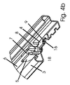
図1は、自動車シートに連結することができるアッパーレール2と、車両の床に連結することができるロアレール3とを有するシートレール1の例示的な実施形態を示す。
FIG. 1 shows an exemplary embodiment of a seat rail 1 having an upper rail 2 that can be connected to an automobile seat and a
自動車シート(ここには図示せず)の車両の床(同じく図示せず)に対する前後(縦方向)調節のために、アッパーレール2は、縦方向に変位可能にロアレール3に取り付けられ、調節装置を用いた、シートロアレール2において簡単に行える前後調節のために、スピンドル6が、スピンドルリテーナ4とスピンドル受け部11とを介して回転が固定された形でロアレール3に取り付けられている。
The upper rail 2 is attached to the
調節装置(ここには図示せず)の従動スピンドルナットと相互作用するスピンドル6は、アッパーレール2がモータ駆動でロアレール3に対して変位することを可能にする。このような調節機能は、手動の前後調節に比べて楽さが増しており、その位置決めを固定するために、ロアレール3上にくぼみ13が設けられているが、それらはモータ駆動の調節の際には機能しない。
A spindle 6 interacting with a driven spindle nut of an adjusting device (not shown here) allows the upper rail 2 to be displaced relative to the
スピンドル6の一端は、スピンドル受け部11に固定され、スピンドル受け部11は、スタンピング12を用いて回転が固定されるようにロアレール3に固定される。他端において、スピンドル6は、ロアレール3にスピンドルリテーナ4を介して接続され、スピンドルリテーナ4は、第1締結穴20と第2締結穴9とを有し、ロアレール3は、第1締結穴17と第2締結穴16とを有する(図2〜4c参照)。
One end of the spindle 6 is fixed to the
第1締結穴20,17及び第2締結穴9,16は、スピンドルリテーナ4のロアレール3上への設置位置において互いに整列して配置される。第1締結穴20,17は、多角形の、すなわち六角形の断面を有し、連結部18が対応する六角形の断面を有する連結リベットの形をした対応する形状の締結要素8,8’の配置を可能にする。締結リベット8,8’は、第1締結穴20,17を通って延び、連結部18の多角形断面と締結穴20,17の対応する設計によってロアレール3に対するスピンドルリテーナ4の回転を防止する。
The first fastening holes 20, 17 and the second fastening holes 9, 16 are arranged in alignment with each other at the installation position of the
シートレール1を車両床に締結する締結ボルト10が第2締結穴9,16を通って延びて車両床に留められる場合、締結ボルト10の締め付け時に、締結ボルト10とスピンドルリテーナ4との間の摩擦によってトルクが生じ、トルクがスピンドルリテーナ4の回転を引き起こすことがあり、その結果としてスピンドル6の曲がりの原因となり、同様に剛性に影響が出るので、回転に対する適切なロックが特に有利である。
When the
スピンドルリテーナ4上にスピンドル6を回転しないようにロックして配置するため、スピンドルリテーナ4はU字形収容部5を有し、U字形収容部5は自由リムでスピンドル6の平坦な連結部7を取り囲む。
In order to lock the spindle 6 so as not to rotate on the
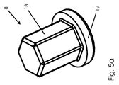
締結するために、リベット8,8’として設計された締結要素は、連結部18を用いて回転を防ぐロックが存在することが保証されていれば、任意の設計を有することができる。図5aに示す実施形態によれば、締結手段は、その連結部18がスピンドルリテーナ4とロアレール3の第1締結穴20,17内にあるリベット8として設計され、位置決めがリベット頭部19を用いて固定される。図5bは締結要素の第2実施形態を示し、締結リベット8’は、連結部18に取り付けられた、先細の断面を有するペグ15を有する。設置位置において、ペグ15は、特に図3bに見られるように、ロアレール3の下側14から突出し、リベット8’が回転に対するロックと共に、車両床にシートレール1を位置決めするためにも使用されることを可能にする。ここで、端部領域において先細になるペグ15の断面は、組み立ての補助として機能する。
For fastening, the fastening elements designed as
Claims (7)
自動車に連結することができるロアレールと、
前記ロアレール上にスピンドルリテーナによって回転が固定されて配置されるスピンドルであって、前記スピンドルリテーナが、前記スピンドルリテーナの締結穴(20)と前記ロアレールの締結穴(17)とを通って延びる締結要素によって前記ロアレールに固定されるスピンドルと
を有し、
前記締結穴(17,20)及び/又は前記締結要素(8,8’)が、前記締結穴(17、20)の領域に配置された連結部(18)において、円形から外れた断面を有し、
前記ロアレール(3)の前記スピンドルリテーナ(4)と反対側の面から突出するペグ(15)が、前記締結要素(8’)の前記連結部(18)に取り付けられる、シートレール。 A seat rail for an automobile seat,
A lower rail that can be connected to a car,
A spindle arranged on the lower rail with its rotation fixed by a spindle retainer, the spindle retainer extending through a fastening hole (20) of the spindle retainer and a fastening hole (17) of the lower rail And a spindle fixed to the lower rail by
The fastening hole (17, 20) and / or the fastening element (8, 8 ') is, in the fastening hole (17, 20) connecting portions which are arranged in the region of (18), have a cross section that deviates from a circular And
A seat rail in which a peg (15) protruding from a surface of the lower rail (3) opposite to the spindle retainer (4) is attached to the connecting portion (18) of the fastening element (8 ') .
Applications Claiming Priority (3)
| Application Number | Priority Date | Filing Date | Title |
|---|---|---|---|
| DE102011002441A DE102011002441A1 (en) | 2011-01-04 | 2011-01-04 | Seat rail for a motor vehicle seat |
| DE102011002441.7 | 2011-01-04 | ||
| PCT/EP2011/071267 WO2012093002A1 (en) | 2011-01-04 | 2011-11-29 | Seat rail for a motor vehicle seat |
Publications (2)
| Publication Number | Publication Date |
|---|---|
| JP2014501662A JP2014501662A (en) | 2014-01-23 |
| JP5771703B2 true JP5771703B2 (en) | 2015-09-02 |
Family
ID=45350750
Family Applications (1)
| Application Number | Title | Priority Date | Filing Date |
|---|---|---|---|
| JP2013547829A Expired - Fee Related JP5771703B2 (en) | 2011-01-04 | 2011-11-29 | Seat rail for automobile seat |
Country Status (7)
| Country | Link |
|---|---|
| US (1) | US9242579B2 (en) |
| EP (1) | EP2661380B1 (en) |
| JP (1) | JP5771703B2 (en) |
| KR (1) | KR101547107B1 (en) |
| CN (1) | CN103298650B (en) |
| DE (1) | DE102011002441A1 (en) |
| WO (1) | WO2012093002A1 (en) |
Families Citing this family (9)
| Publication number | Priority date | Publication date | Assignee | Title |
|---|---|---|---|---|
| USD754521S1 (en) * | 2012-12-28 | 2016-04-26 | Thk Co., Ltd. | Vehicle seat rail |
| FR3025756B1 (en) | 2014-09-12 | 2018-03-16 | Faurecia Sieges D'automobile | SLIDERS FOR VEHICLE SEATS, VEHICLE SEAT COMPRISING SUCH A SLIDER |
| KR101600191B1 (en) | 2014-09-30 | 2016-03-07 | 주식회사다스 | Seat rail for vehicle |
| DE102015203763A1 (en) | 2015-03-03 | 2016-09-08 | Volkswagen Aktiengesellschaft | Device for securing a seat in a vehicle, vehicle seat arrangement |
| CN107428264A (en) * | 2015-03-20 | 2017-12-01 | 安道拓卢森堡控股有限公司 | Longitudinal adjusting mechanism for seat |
| DE102016224514A1 (en) * | 2016-12-08 | 2018-06-14 | Brose Fahrzeugteile Gmbh & Co. Kg, Coburg | Adjustment device for the longitudinal adjustment of a vehicle seat |
| DE102017218492B4 (en) * | 2017-08-08 | 2022-12-22 | Keiper Seating Mechanisms Co., Ltd. | FOREIGN ADJUSTER AND VEHICLE SEAT |
| DE102020102867A1 (en) * | 2019-10-02 | 2021-04-08 | Adient Engineering and IP GmbH | LENGTH ADJUSTER FOR ONE VEHICLE SEAT AND VEHICLE SEAT |
| FR3106538B1 (en) * | 2020-01-29 | 2022-01-14 | Faurecia Sieges Dautomobile | Vehicle seat slider attachment |
Family Cites Families (17)
| Publication number | Priority date | Publication date | Assignee | Title |
|---|---|---|---|---|
| GB931839A (en) | 1960-08-09 | 1963-07-17 | Goodrich Co B F | Expansible hollow rivet |
| JPS57198224U (en) * | 1981-06-12 | 1982-12-16 | ||
| DE19639007A1 (en) * | 1996-09-23 | 1998-03-26 | Boellhoff Gmbh Verbindungs Und | Method for riveting a fixture element into a retainer hole in a sheet-metal work piece |
| JPH111136A (en) | 1997-06-12 | 1999-01-06 | Gifu Shatai Kogyo Kk | Parts fixing structure in seat track slide device |
| EP0979750A3 (en) * | 1998-08-12 | 2001-04-11 | C. Rob. Hammerstein GmbH & Co.KG | Vehicle seat adjusting device with a spindle and a spindle nut |
| GB0107664D0 (en) | 2001-03-28 | 2001-05-16 | Emhart Inc | Blind rivet nut with improved seal retention |
| JP2004106713A (en) | 2002-09-19 | 2004-04-08 | Shiroki Corp | Power seat track |
| DE10358586B4 (en) * | 2003-12-08 | 2008-02-21 | Keiper Gmbh & Co.Kg | Transmission housing of a Sitzverstellgetriebes for a motor vehicle |
| DE102004001624B3 (en) | 2004-01-09 | 2005-09-01 | Keiper Gmbh & Co. Kg | Drive a seat adjustment for a motor vehicle |
| DE202005000317U1 (en) * | 2004-02-12 | 2005-04-07 | Keiper Gmbh & Co Kg | Spindle for a length adjustable seat mounting in vehicle has a metal tube with outer thread and with one end shaped into a support flange and with a separate support flange secured to the other end |
| JP4484549B2 (en) | 2004-03-09 | 2010-06-16 | 富士機工株式会社 | Automotive seat slide device |
| JP4857558B2 (en) * | 2004-12-21 | 2012-01-18 | アイシン精機株式会社 | Power seat slide device for vehicle |
| US7407214B2 (en) * | 2005-01-18 | 2008-08-05 | Dura Global Technologies, Inc. | Seat adjusting assembly including lead screw and mounting attachment |
| FR2882974B1 (en) * | 2005-03-14 | 2008-11-07 | Faurecia Sieges Automobile | SCREW ADJUSTING MECHANISM, SLIDER COMPRISING SUCH AN ADJUSTING MECHANISM AND SEAT COMPRISING SUCH A SLIDER |
| DE102006022947B3 (en) | 2006-05-17 | 2007-09-27 | Keiper Gmbh & Co.Kg | Longitudinal adjuster for vehicle seat has transmission with bearing elements adapted to special bearing and selected from set of several possible bearing elements or first manufactured identically and then modified on assembly |
| JP5365225B2 (en) | 2009-02-03 | 2013-12-11 | トヨタ紡織株式会社 | Slide structure for vehicle seat |
| US8540203B2 (en) * | 2009-12-16 | 2013-09-24 | Keiper Gmbh & Co. Kg | Longitudinal adjuster for a vehicle seat with spindle and spindle holder |
-
2011
- 2011-01-04 DE DE102011002441A patent/DE102011002441A1/en not_active Withdrawn
- 2011-11-29 WO PCT/EP2011/071267 patent/WO2012093002A1/en active Application Filing
- 2011-11-29 US US13/978,371 patent/US9242579B2/en active Active
- 2011-11-29 JP JP2013547829A patent/JP5771703B2/en not_active Expired - Fee Related
- 2011-11-29 CN CN201180064093.9A patent/CN103298650B/en active Active
- 2011-11-29 EP EP11797210.9A patent/EP2661380B1/en active Active
- 2011-11-29 KR KR1020137020687A patent/KR101547107B1/en not_active IP Right Cessation
Also Published As
| Publication number | Publication date |
|---|---|
| JP2014501662A (en) | 2014-01-23 |
| DE102011002441A1 (en) | 2012-07-05 |
| KR20130114711A (en) | 2013-10-17 |
| EP2661380B1 (en) | 2015-07-15 |
| KR101547107B1 (en) | 2015-08-25 |
| CN103298650B (en) | 2016-05-11 |
| WO2012093002A1 (en) | 2012-07-12 |
| US9242579B2 (en) | 2016-01-26 |
| US20140374560A1 (en) | 2014-12-25 |
| CN103298650A (en) | 2013-09-11 |
| EP2661380A1 (en) | 2013-11-13 |
Similar Documents
| Publication | Publication Date | Title |
|---|---|---|
| JP5771703B2 (en) | Seat rail for automobile seat | |
| JP6028872B2 (en) | Steering device | |
| US8113561B2 (en) | Mounting structure of door grip | |
| JP5279743B2 (en) | Steering position adjustment device | |
| JP5240179B2 (en) | Tilt-type steering device | |
| US20160244100A1 (en) | Load transmission member | |
| JP2005280692A (en) | Child seat tether anchor structure | |
| JP2011156878A (en) | Steering device for automobile | |
| KR100988444B1 (en) | Fixing device for a seat belt winder | |
| US9415704B2 (en) | Vehicle seat having an adjusting device | |
| SE508335C2 (en) | Arrangement and procedure for attaching a seat to the seat base of a vehicle | |
| EP2489581A1 (en) | Screen attachment structure for saddle riding type vehicle | |
| JP2003341469A (en) | Shoulder adjuster device | |
| JP4699630B2 (en) | Railcar wheel tread cleaning device | |
| JP4599605B2 (en) | Car seat mounting structure | |
| JP5185070B2 (en) | Loading hook mounting structure | |
| JP5212388B2 (en) | Steering column support device | |
| CN112849183A (en) | Vehicle seat and rail vehicle | |
| KR101724899B1 (en) | Appratus for guiding tilting and telescoping of steering column for vehicle | |
| JP2021030985A (en) | Electrically-driven seat slide device | |
| JP5161591B2 (en) | Support bracket | |
| JP4809274B2 (en) | Instrument panel mounting structure | |
| JP4105411B2 (en) | Seat rail shoulder adjuster guide rail mounting structure | |
| JP5857926B2 (en) | Seat back striker mounting structure | |
| JP3846701B2 (en) | Non-rotating structure for mounting parts |
Legal Events
| Date | Code | Title | Description |
|---|---|---|---|
| A621 | Written request for application examination |
Free format text: JAPANESE INTERMEDIATE CODE: A621 Effective date: 20130806 |
|
| A977 | Report on retrieval |
Free format text: JAPANESE INTERMEDIATE CODE: A971007 Effective date: 20140806 |
|
| A131 | Notification of reasons for refusal |
Free format text: JAPANESE INTERMEDIATE CODE: A131 Effective date: 20140812 |
|
| A521 | Written amendment |
Free format text: JAPANESE INTERMEDIATE CODE: A523 Effective date: 20141110 |
|
| TRDD | Decision of grant or rejection written | ||
| A01 | Written decision to grant a patent or to grant a registration (utility model) |
Free format text: JAPANESE INTERMEDIATE CODE: A01 Effective date: 20150602 |
|
| A61 | First payment of annual fees (during grant procedure) |
Free format text: JAPANESE INTERMEDIATE CODE: A61 Effective date: 20150629 |
|
| R150 | Certificate of patent or registration of utility model |
Ref document number: 5771703 Country of ref document: JP Free format text: JAPANESE INTERMEDIATE CODE: R150 |
|
| LAPS | Cancellation because of no payment of annual fees |