JP5760141B2 - Air shield window - Google Patents
Air shield window Download PDFInfo
- Publication number
- JP5760141B2 JP5760141B2 JP2014500986A JP2014500986A JP5760141B2 JP 5760141 B2 JP5760141 B2 JP 5760141B2 JP 2014500986 A JP2014500986 A JP 2014500986A JP 2014500986 A JP2014500986 A JP 2014500986A JP 5760141 B2 JP5760141 B2 JP 5760141B2
- Authority
- JP
- Japan
- Prior art keywords
- frame
- window glass
- window
- operating
- upper frame
- Prior art date
- Legal status (The legal status is an assumption and is not a legal conclusion. Google has not performed a legal analysis and makes no representation as to the accuracy of the status listed.)
- Expired - Fee Related
Links
- 239000005357 flat glass Substances 0.000 claims description 181
- 238000009434 installation Methods 0.000 claims description 37
- 238000000034 method Methods 0.000 claims description 15
- 238000010168 coupling process Methods 0.000 claims description 3
- 230000008878 coupling Effects 0.000 claims description 2
- 238000005859 coupling reaction Methods 0.000 claims description 2
- 239000011521 glass Substances 0.000 claims description 2
- 230000000149 penetrating effect Effects 0.000 claims description 2
- 230000000903 blocking effect Effects 0.000 description 7
- 230000000694 effects Effects 0.000 description 6
- 238000009413 insulation Methods 0.000 description 6
- 238000004891 communication Methods 0.000 description 3
- 238000010276 construction Methods 0.000 description 2
- 210000000050 mohair Anatomy 0.000 description 2
- 208000003028 Stuttering Diseases 0.000 description 1
- 238000005452 bending Methods 0.000 description 1
- 238000007429 general method Methods 0.000 description 1
- 238000003780 insertion Methods 0.000 description 1
- 230000037431 insertion Effects 0.000 description 1
- 238000012986 modification Methods 0.000 description 1
- 230000004048 modification Effects 0.000 description 1
- 238000000926 separation method Methods 0.000 description 1
Images


Classifications
-
- E—FIXED CONSTRUCTIONS
- E06—DOORS, WINDOWS, SHUTTERS, OR ROLLER BLINDS IN GENERAL; LADDERS
- E06B—FIXED OR MOVABLE CLOSURES FOR OPENINGS IN BUILDINGS, VEHICLES, FENCES OR LIKE ENCLOSURES IN GENERAL, e.g. DOORS, WINDOWS, BLINDS, GATES
- E06B3/00—Window sashes, door leaves, or like elements for closing wall or like openings; Layout of fixed or moving closures, e.g. windows in wall or like openings; Features of rigidly-mounted outer frames relating to the mounting of wing frames
- E06B3/32—Arrangements of wings characterised by the manner of movement; Arrangements of movable wings in openings; Features of wings or frames relating solely to the manner of movement of the wing
- E06B3/34—Arrangements of wings characterised by the manner of movement; Arrangements of movable wings in openings; Features of wings or frames relating solely to the manner of movement of the wing with only one kind of movement
- E06B3/42—Sliding wings; Details of frames with respect to guiding
- E06B3/44—Vertically-sliding wings
-
- E—FIXED CONSTRUCTIONS
- E06—DOORS, WINDOWS, SHUTTERS, OR ROLLER BLINDS IN GENERAL; LADDERS
- E06B—FIXED OR MOVABLE CLOSURES FOR OPENINGS IN BUILDINGS, VEHICLES, FENCES OR LIKE ENCLOSURES IN GENERAL, e.g. DOORS, WINDOWS, BLINDS, GATES
- E06B3/00—Window sashes, door leaves, or like elements for closing wall or like openings; Layout of fixed or moving closures, e.g. windows in wall or like openings; Features of rigidly-mounted outer frames relating to the mounting of wing frames
- E06B3/54—Fixing of glass panes or like plates
-
- E—FIXED CONSTRUCTIONS
- E06—DOORS, WINDOWS, SHUTTERS, OR ROLLER BLINDS IN GENERAL; LADDERS
- E06B—FIXED OR MOVABLE CLOSURES FOR OPENINGS IN BUILDINGS, VEHICLES, FENCES OR LIKE ENCLOSURES IN GENERAL, e.g. DOORS, WINDOWS, BLINDS, GATES
- E06B7/00—Special arrangements or measures in connection with doors or windows
- E06B7/16—Sealing arrangements on wings or parts co-operating with the wings
-
- E—FIXED CONSTRUCTIONS
- E06—DOORS, WINDOWS, SHUTTERS, OR ROLLER BLINDS IN GENERAL; LADDERS
- E06B—FIXED OR MOVABLE CLOSURES FOR OPENINGS IN BUILDINGS, VEHICLES, FENCES OR LIKE ENCLOSURES IN GENERAL, e.g. DOORS, WINDOWS, BLINDS, GATES
- E06B3/00—Window sashes, door leaves, or like elements for closing wall or like openings; Layout of fixed or moving closures, e.g. windows in wall or like openings; Features of rigidly-mounted outer frames relating to the mounting of wing frames
- E06B3/32—Arrangements of wings characterised by the manner of movement; Arrangements of movable wings in openings; Features of wings or frames relating solely to the manner of movement of the wing
- E06B3/34—Arrangements of wings characterised by the manner of movement; Arrangements of movable wings in openings; Features of wings or frames relating solely to the manner of movement of the wing with only one kind of movement
- E06B3/42—Sliding wings; Details of frames with respect to guiding
- E06B3/44—Vertically-sliding wings
- E06B2003/4484—Special provisions for mounting or dismounting sashes
Landscapes
- Engineering & Computer Science (AREA)
- Civil Engineering (AREA)
- Structural Engineering (AREA)
- Specific Sealing Or Ventilating Devices For Doors And Windows (AREA)
- Wing Frames And Configurations (AREA)
Description
本発明は、摺動方式で開閉されるエアシールドウィンドウに関し、特に、窓ガラスを窓ガラスフレームに挿入する場合、斜めに挿入するための空間を確保すると共に、窓ガラスが設けられると室内及び室外が連通する空間を遮ることで、断熱性を増大し、騷音が室内へ流入されることを防止することができるエアシールドウィンドウに関する。 The present invention relates to an air shield window that is opened and closed by a sliding method, and in particular, when a window glass is inserted into a window glass frame, it secures a space for insertion obliquely, and when the window glass is provided, indoors and outdoors. It is related with the air shield window which can prevent that a noise is flowed into a room | chamber interior by blocking the space which communicates, and increasing heat insulation.
一般的に、多世帯住宅とアパートなどの各種建築物には、自然採光機能と、室内から室外を観望する機能と、室内の空気を換気させる機能と、が提供される摺動ウィンドウが設けられる。 In general, various buildings such as multi-family houses and apartments are provided with sliding windows that provide a natural daylighting function, a function of observing the room from the outside, and a function of ventilating the indoor air. .
このような摺動ウィンドウは、外部と内部とを連結してくれるものであり、窓ガラスを開けた時には、室内で外部からの快適な空気と日差しを楽しむことができ、窓ガラスを閉めた時には、外部からの騷音と悪い空気、暴雨、冷風、暑気、荒風から保護される必要である。すなわち、摺動ウィンドウにおいては、防音性、気密性、水密性、断熱性が非常に重要である。 Such a sliding window connects the outside and the inside. When you open the window glass, you can enjoy comfortable air and sunlight from the outside indoors, and when you close the window glass. Need to be protected from external noise, bad air, storms, cold winds, heat and storms. That is, in the sliding window, soundproofing, airtightness, watertightness, and heat insulation are very important.
従来の摺動ウィンドウは、レールが備えられた上下水平窓額縁と、左右垂直窓額縁とで構成されて壁に固定される窓額縁、前記窓額縁に左右に開閉可能に設けられ、レール溝が備えられた上下水平窓ガラスフレームと、左右垂直窓ガラスフレームとで構成された窓ガラス、前記レール溝の内部の前後方にそれぞれ設けられるモヘアで構成される。 A conventional sliding window is composed of an upper and lower horizontal window frame provided with rails, and a left and right vertical window frame, and is fixed to a wall. It is comprised with the window glass comprised by the up-and-down horizontal window glass frame with which it was equipped, and the right-and-left vertical window glass frame, and the mohair respectively provided in the front and back inside the said rail groove | channel.
このように構成された摺動ウィンドウは、窓ガラスのレール溝が窓額縁のレールにそれぞれ挟まれ、この際、レール溝に設けられたモヘアがレールの前面と後面にそれぞれ密着することで、防音効果及び防風効果を与えるようになる。 The sliding window constructed in this manner is soundproofed by having the window glass rail groove sandwiched between the window frame rails, and the mohair provided in the rail groove in close contact with the front and rear surfaces of the rail. An effect and a windbreak effect are given.
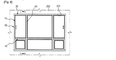
しかし、上記のような従来の摺動ウィンドウは、図1に示すように、摺動方式で開閉される窓ガラスフレーム1aからなる窓ガラス1が結合して移動するレール2が形成された上側フレーム3、下側フレーム4、左側フレーム5、右側フレーム6を四角フレームにして建物に設ける窓額縁7で構成される。
However, as shown in FIG. 1, the conventional sliding window as described above has an upper frame formed with a
このような、前記従来の摺動ウィンドウは、前記窓額縁7を施工した後、窓ガラス1を設ける場合、窓ガラス1の上部端を窓額縁7の上側フレーム3の内部に挿入し、窓ガラス1の下部端が下側フレーム4の上部に置かれるようにする結合方式を用いる。
In such a conventional sliding window, when the
しかし、上記従来の摺動ウィンドウは、窓ガラスを窓ガラスフレームに設けるためには、上側フレームの内部が長い必要があり、これによって、窓ガラスを設けた後、下側フレームに置かれると、窓ガラスの上部端と上側フレームとの間隔が大きく離隔してしまい、断熱性が劣化し、騷音が流入される問題があった。 However, the above-mentioned conventional sliding window requires the inside of the upper frame to be long in order to provide the window glass on the window glass frame, so that when the window glass is provided and then placed on the lower frame, There was a problem that the space between the upper end of the window glass and the upper frame was greatly separated, the heat insulation was deteriorated, and noise was introduced.
ここで、本発明は、上記のような従来技術の問題点を勘案して案出したものであって、窓ガラスを窓ガラスフレームに設ける場合、下側フレームに置かれるよう窓ガラスの上部末端が上部に位置したフレームの内部に挿入されるように、上側フレームの内部から上下方向に摺動作動する稼動フレームを設置して、窓ガラスの設置が容易になるようにする上側フレームを提供することに目的がある。 Here, the present invention has been devised in view of the problems of the prior art as described above, and when the window glass is provided on the window glass frame, the upper end of the window glass is placed on the lower frame. An upper frame is provided in which an operating frame that slides up and down from the inside of the upper frame is installed so that the window glass can be easily installed so that the window glass can be inserted into the upper frame. There is a purpose.
そして、本発明の他の目的は、窓ガラスが窓ガラスフレームに設けられた後、上側フレームの内部に設けられた稼動フレームが自重によって窓ガラスの上部末端と密着するようにし、室内及び室外の連通を防止することで、断熱性の増大及び騷音の遮断ができるようにすることにある。 Another object of the present invention is that after the window glass is provided on the window glass frame, the operating frame provided inside the upper frame is in close contact with the upper end of the window glass by its own weight, By preventing communication, it is possible to increase heat insulation and block noise.
さらに、本発明の他の目的は、上側フレームと稼動フレームとの間に弾性手段を設け、稼動フレームを弾性力により下部に押して、窓ガラスの上部末端と密着させることで、断熱性の増大及び騷音の遮断をより緊密にすることにある。 Furthermore, another object of the present invention is to provide an elastic means between the upper frame and the working frame, and push the working frame to the lower part by elastic force so as to be in close contact with the upper end of the window glass. The purpose is to make the noise blocker closer.
尚、本発明の他の目的は、一般的な上側フレームに稼動フレームをネジ軸とナットを用いて結合することができ、汎用性が増大されるようにすることにある。 Another object of the present invention is to connect a working frame to a general upper frame using a screw shaft and a nut, so that versatility is increased.
上記の目的を達成するため、本発明は、摺動方式で開閉される窓ガラスフレームからなる窓ガラスが結合して移動するレールが形成された上側フレーム、下側フレーム、左側フレーム、右側フレームを四角フレームにして建物に設ける窓ガラスフレーム上側フレームにおいて、前記上側フレームは、下部に開放された匚字の形態で建物の設置部に密着して設けられる設置端の両末端が、下部に延長された末端が内側に折曲して対向するように折曲端を形成し、前記上側フレームの折曲端に置かれて係止される係止端が両末端に形成され、前記係止端を連結する胴体端の下部面に多数のレールからなる下部が開放された匚字状の稼動フレームを形成し、前記稼動フレームを上側フレームの内部に挿入して、係止端を折曲端に係止させ、前記上側フレームの両側に、下側フレームに連結された左側フレームと右側フレームとを連結した後、窓ガラスを設ける場合、前記窓ガラスの上部端は稼動フレームを押し上げて窓ガラスが窓ガラスアフレーム内に設けられる余裕空間を確保すると共に、下部端は下側フレームに置かれ、前記窓ガラスが設けられると稼動フレームが自重によって下部に移動され、上側フレームに密着され、室内及び室外を遮るように構成することを特徴とするエアシールドウィンドウを提供する。 In order to achieve the above object, the present invention includes an upper frame, a lower frame, a left frame, and a right frame, which are formed with rails on which a window glass composed of a window glass frame that is opened and closed by a sliding method is coupled. In the upper frame of the window glass frame provided in the building as a square frame, the upper frame is extended in the lower part at both ends of the installation end that is provided in close contact with the installation part of the building in the form of a square opened at the lower part. A bent end is formed so that the end is bent inward and opposed to each other, and a lock end that is placed and locked on the bent end of the upper frame is formed at both ends, and the lock end is A hook-shaped working frame consisting of a number of rails is formed on the lower surface of the body end to be connected. The working frame is inserted into the upper frame, and the locking end is engaged with the bent end. The upper side When the window glass is provided after connecting the left frame and the right frame connected to the lower frame on both sides of the frame, the upper end of the window glass pushes up the operating frame so that the window glass is in the window glass frame. The space is provided, and the lower end is placed on the lower frame, and when the window glass is installed, the operating frame is moved to the lower part by its own weight and is in close contact with the upper frame to block the room and the outside. An air shield window is provided.
以上のように、本発明は、窓ガラスを窓ガラスフレームに設ける場合、下側フレームに置かれるよう窓ガラスの上部末端が上部に位置したフレームの内部に挿入されるよう、上側フレームの内部から上下方向に摺動作動する稼動フレームを設けることで、窓ガラスの設置が容易になるようにする効果がある。 As described above, according to the present invention, when the window glass is provided on the window glass frame, the upper end of the window glass is inserted into the upper frame so as to be placed on the lower frame. By providing an operation frame that slides in the vertical direction, there is an effect of facilitating the installation of the window glass.
そして、窓ガラスが窓ガラスフレームに設けられた後、上側フレームの内部に設けられた稼動フレームが自重によって窓ガラスの上部末端と密着するようにし、室内及び室外の連通を防止することで、断熱性の増大及び騷音の遮断ができるようにする効果がある。 Then, after the window glass is provided on the window glass frame, the operation frame provided inside the upper frame is brought into close contact with the upper end of the window glass by its own weight, thereby preventing indoor and outdoor communication, It has the effect of enabling the increase of sex and the blocking of stuttering.
さらに、上側フレームと稼動フレームとの間に弾性手段を設け、稼動フレームを弾性力により下部に押して、窓ガラスの上部末端と密着させることで、断熱性の増大及び騷音の遮断をより緊密にする効果がある。 In addition, an elastic means is provided between the upper frame and the operating frame, and the operating frame is pushed downward by the elastic force so as to be in close contact with the upper end of the window glass. There is an effect to.
尚、一般的な上側フレームに稼動フレームをネジ軸とナットを用いて結合することができ、汎用性を増大させる効果がある。 The operating frame can be coupled to a general upper frame using a screw shaft and a nut, and there is an effect of increasing versatility.
本発明は、窓ガラスを窓ガラスフレームに挿入する場合、斜めに挿入するための空間を確保すると共に、窓ガラスが設けられると室内及び室外が連通する空間を遮ることで、断熱性を増大し、騷音が室内へ流入されることを防止することができるエアシールドウィンドウに関する。 The present invention secures a space for inserting the window glass into the window glass frame obliquely, and increases the heat insulating property by blocking the space where the room communicates with the outside when the window glass is provided. The present invention relates to an air shield window that can prevent noise from flowing into the room.
ここで、上記のような本発明の好ましい実施の形態を、添付した図面に基づいて詳しく説明すると次の通りである。 Here, the preferred embodiments of the present invention as described above will be described in detail with reference to the accompanying drawings.
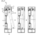
図2〜図4に示すように、本発明のエアシールドウィンドウは、摺動方式で開閉される窓ガラスフレーム11からなる窓ガラス10が結合して移動するレール20が形成された上側フレーム30、下側フレーム40、左側フレーム50、右側フレーム60を四角フレームにして建物に設ける窓額縁70の上側フレーム30に関するものである。
As shown in FIGS. 2 to 4, the air shield window of the present invention has an
先ず、本発明では、2つの形態の窓ガラス10を説明することにし、1つの窓ガラス10は窓ガラスフレーム11があるものであり、その他には、窓ガラスフレーム11の無い縁無しの窓ガラス10と使われる上側フレーム30の構造を説明することにする。
First, in the present invention, two types of
1. 窓ガラスフレーム11がある窓ガラス10と使われる上側フレーム30は;
先ず、前記上側フレーム30は、下部に開放された匚字状で建物200の設置部201に密着して設けられる設置端31の両末端が下部に延長された末端が内側に折曲して対向するように折曲端32が形成される。
1. The
First, the
この際、前記折曲端32は、設置端31の両末端の下部面の下部方向に一体で延長される延長端32aの下部末端に形成される。
At this time, the
そして、前記上側フレーム30の折曲端32に置かれて係止される係止端81が両末端に形成され、前記係止端81を連結する胴体端82の下部面に多数のレール20からなる下部が開放された匚字状の稼動フレーム80を形成する。
Locking ends 81 placed on the bent ends 32 of the
ここで、前記稼動フレーム80は、長さの方向に直角になるよう断面を切った状態で、横幅の長さは上側フレーム30の延長端32aの離隔距離より小さく形成され、稼動フレーム80が上側フレーム30の長さ、または内部から上下方向に摺動移動可能に構成されたものである。
Here, the working
2. 図8〜図10に示すように、窓ガラスフレーム11の無い縁無しの窓ガラス10と使われる上側フレーム30は;
摺動方式で開閉される窓ガラスフレームの無い窓ガラス10が結合して移動する上側フレーム30、下側フレーム40、左側フレーム50、右側フレーム60を四角フレームにして建物に設ける窓額縁70の上側フレーム30に関するものである。
2. As shown in FIGS. 8-10, the
The upper side of the
先ず、前記上側フレーム30は、下部に開放された匚字状(C字状)で建物200の設置部201に密着して設けられる設置端31の両末端が下部に延長された末端が内側に折曲して対向するように折曲端32が形成される。
First, the
この際、前記折曲端32は、設置端31の両末端の下部面の下部方向に一体で延長される延長端32aの下部末端に形成される。
At this time, the
そして、前記上側フレーム30の折曲端32に置かれて係止される係止端81が両末端に形成される。
Then, locking ends 81 that are placed and locked at the bent ends 32 of the
このように、前記係止端81を連結する胴体端82の中央下部に分割端84が形成され、係止端81と分割端84との間に多数のガイド溝85からなる下部が開放された匚字状の稼動フレーム80を形成する。
As described above, the
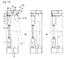
図5〜図7、図11〜図13に示すように、前記窓ガラスフレーム11の有無による窓ガラス10が設けられる上側フレーム30に共通して、上側フレーム30と稼動フレーム80との間には弾性手段90を挿入して構成することができる。
As shown in FIGS. 5 to 7 and FIGS. 11 to 13, in common with the
このように、前記弾性手段90は、窓ガラス10を設ける場合、上側フレーム30に支持されて押し上げられる稼動フレーム80によって加圧された後、窓ガラス10の設置が完了すると弾性力によって稼動フレーム80を下部に復帰させるように構成するものである。
As described above, when the
図14及び図15aに示すように、一実施の形態として、前記弾性手段90は、半円筒状に構成され、上側フレーム30に両末端が自由に支持されるか、一末端を固定して構成するものである。
As shown in FIGS. 14 and 15a, as one embodiment, the elastic means 90 is formed in a semi-cylindrical shape, and both ends are freely supported by the
ここで、前記弾性手段90は、半円筒状であり、両末端は扁平に形成し、上側フレーム30や稼動フレーム80を支持することができる支持端91が一体に形成される。(図14の(a)を参照)
Here, the elastic means 90 has a semi-cylindrical shape, both ends are formed flat, and a
さらに、他の実施の形態として、前記弾性手段90は、両末端の直径が同一なコイルバネ(図14の(b)を参照)、または円錐状のコイルバネ(図14の(c)を参照)の中、何れか1つで構成する。 Furthermore, as another embodiment, the elastic means 90 includes a coil spring having the same diameter at both ends (see FIG. 14B) or a conical coil spring (see FIG. 14C). Any one of them.
そして、前記弾性手段90がコイルバネで構成し、上下の一末端や両末端を上側フレーム30や稼動フレーム80に固定して結合することで、弾性手段80の動きが防止されるように構成することもできる。
The elastic means 90 is constituted by a coil spring, and the upper and lower ends or both ends are fixedly coupled to the
図15に示すように、前記支持端91は、上側フレーム30や稼動フレーム80に固定せずに自由端で維持させることも可能であり、一末端のみを上側フレーム30や稼動フレーム80に固定し、加圧する際に他の末端が押されて加圧可能になるように構成することも可能である。
As shown in FIG. 15, the
この際、前記弾性手段90は、上側フレーム30や稼動フレーム80の長さ方向に沿って等間隔の配置で多数個を一列や他列に配置して設けることができ、弾性板の場合、長さを長く形成して使用できるよう窓・戸フレーム100が構成される。
At this time, the elastic means 90 can be arranged in a single row or in other rows at equal intervals along the length direction of the
他の実施の形態として、図16〜図19に示すように、前記上側フレーム30に稼動フレーム80が置かれて係止されずにネジ軸87とナット88で連結して構成される。
As another embodiment, as shown in FIGS. 16 to 19, an
ここで、前記上側フレーム30は下部に開放された匚字状で建物200の設置部201に密着して設けられる設置端31の両末端に上側孔33を貫通して形成する。
Here, the
そして、前記上側フレーム30の設置端31の下部面に密着され、上側孔33と同一線上に稼動孔86が胴体端82を貫通して形成する。
An
さらに、前記胴体端82の下部面に多数のレール20からなる下部が開放された匚字状の稼動フレーム80を形成する。
In addition, the lower frame of the
尚、前記上側フレーム30の上側孔33と稼動フレーム80の稼動孔86に両末端がそれぞれ貫通するネジ軸87にナット88を締結する。
A
この際、前記上側フレーム30と稼動フレーム80は、大部の長さが長い形態に製作され、上側孔33と稼動孔86は両末端の部分に形成され、手や締結工具を用いて上側孔33と稼動孔86を通じて露出されるネジ軸87の両末端にナット88を締結することができるように構成される。
At this time, the
一方、前記ネジ軸87は、円柱状であり、両末端に限って数螺旋端が形成されることが望ましく、ネジ軸87は一末端には釘やリベットのような頭部が形成され、他の末端には数螺旋端が形成された形態でも構成可能であろう。
On the other hand, the
そして、前記上側フレーム30と稼動フレーム80との間には弾性手段90を挿入する。
An elastic means 90 is inserted between the
この際、前記弾性手段90は、窓ガラス10を設ける場合、上側フレーム30に支持されて押し上げられる稼動フレーム80によって加圧された後、窓ガラス10の設置が完了すると、弾性力によって稼動フレーム80を下部に復帰させるように構成する。
At this time, when the
このような前記弾性手段90はスポンジであり、スポンジなどのようなクッション力を有するクッション部材で構成して窓・戸フレーム100Aを構成するものである。
The elastic means 90 is a sponge, and is composed of a cushion member having a cushioning force such as a sponge to constitute the window /
図20に示すように、前記上側フレーム30と稼動フレーム80との間に挿入される弾性手段90をコイル状のバネで構成し、前記バネの上部端は上側フレーム30の天井面に付着され、バネの下部端は稼動フレーム80の屋根面に固定して構成することもできる。
As shown in FIG. 20, the elastic means 90 inserted between the
図21〜図23に示すように、他の実施の形態として、摺動方式で開閉される窓ガラスフレーム11からなる窓ガラス10が結合して移動するレール20が形成された上側フレーム30、下側フレーム40、左側フレーム50、右側フレーム60を四角フレームにして建物に設ける窓額縁70の上側フレームに関するものである。
As shown in FIGS. 21 to 23, as another embodiment, an
この際、前記上側フレーム30は、下部に開放された匚字状で建物200の設置部201に密着して設けられる設置端31の両末端が下部に延長された末端が内側に折曲して対向するように折曲端32を形成する。
At this time, the
そして、前記上側フレーム30の折曲端32に置かれて係止される係止端81が両末端に形成され、前記係止端81を連結する胴体端82の下部面に1つのレール20からなる下部が開放された匚字状の稼動フレーム80を多数形成して窓・戸フレーム100Bを構成する。
A locking
そして、前記稼動フレーム80は、上側フレーム30の折曲端32に置かれて係止される係止端81が両末端に形成され、前記係止端81を連結する胴体端82の下部面に1つの溝20が形成された下部が開放された匚字状の稼動フレーム80を多数構成することもできる。
The operating
図24に示すように、他の実施の形態として、摺動方式で開閉される窓ガラスフレーム11からなる窓ガラス10が結合して移動する上側フレーム30、下側フレーム40、左側フレーム50、右側フレーム60を四角フレームにして建物に設ける窓額縁70の上側フレームに関するものである。
As shown in FIG. 24, as another embodiment, an
ここで、前記上側フレーム30は、下部に開放された匚字状で建物200の設置部201に密着して設けられる設置端31の両末端が下部に延長された末端が内側に折曲して対向するように折曲端32を形成する。
Here, the
この際、前記設置端31の内部面を連結して中央に貫通孔34aが形成される中間端34を構成する。
At this time, an
そして、前記上側フレーム30の貫通孔34aに挟まれる連結端80aの上部末端と下部末端には、それぞれ中間端34に置かれる上部係止端80aと、折曲端32に置かれる下部係止端80bと、が一体に形成された稼動フレーム80を形成して窓・戸フレーム100Bを構成する。
The upper end and the lower end of the connecting
上記のように構成された本発明の作動及び作用を説明すると次の通りである。 The operation and action of the present invention configured as described above will be described as follows.
図5〜図7に示すように、窓ガラスフレーム11がある窓ガラス10を設けるためには;
まず、前記稼動フレーム80を上側フレーム30の内部に挿入し、係止端81を折曲端32に係止させて上側フレーム30を完成する。
To provide a
First, the operating
その後、前記上側フレーム30と下側フレーム40、左側フレーム50、右側フレーム60を四角フレームの形態に連結及び結合して、建物200の設置部201に固定させて窓額縁70の施工を完了する。
Thereafter, the
次に、前記窓額縁70を施工した後、窓ガラス10を設置するための一般的な方式として、窓ガラス10の上部端を窓額縁70の上側フレーム30の内部に挿入し、窓ガラス10の下部端が下側フレーム40の上部に置かれるようにする結合方式を用いる。
Next, after constructing the
これによって、前記窓額縁70に窓ガラス10を設けるためには、必ず窓額縁70の上側フレーム30の内部空間の高さが高くなければならない。
Accordingly, in order to provide the
すなわち、本発明において、窓ガラスフレーム11がある窓ガラス10を窓額縁70に設ける場合、上側フレーム30の内部に設けられ、上下方向に移動可能になるように設けられ、前記窓ガラス10を設ける場合、窓ガラス10の上部端は稼動フレーム80を押し上げて窓ガラス10が窓額縁70内に設けられて余裕空間を確保すると共に、下部端は下側フレーム40に置かれるようになる。
That is, in the present invention, when the
この際、前記窓ガラス10の窓ガラスフレーム11に形成されたレール溝11aにレール20を挿入し、稼動フレーム80を上部に押し上げるようになる。
At this time, the
そして、前記窓ガラス10が設けられると、稼動フレーム80が自重によって下部に移動され、レール溝11aの内部にレール20が緊密に挿入されることで密着され、室内及び室外を遮ることで断熱性の増大及び騷音の遮断が可能になる利点がある。
When the
図11〜図13に示すように、窓ガラスフレーム11の無い縁無しの窓ガラス10を設けるためには;
まず、前記窓額縁70の施工方式は、窓ガラスフレーム11がある窓ガラス10を設けるための方式と同一であり、縁無しの窓ガラス10を窓額縁70に設ける方式も同様に成される。
To provide an
First, the construction method of the
つまり、本発明において、窓ガラスフレーム11の無い縁無しの窓ガラス10を窓額縁70に設ける場合、上側フレーム30の内部に設けられ、上下方向に移動可能に設けられ、前記窓ガラス10を設ける場合、窓ガラス10の上部端は稼動フレーム80を押し上げ、窓ガラス10が窓額縁70内に設けられて余裕空間を確保すると共に、下部端は下側フレーム40に置かれるようになる。
In other words, in the present invention, when the
この際、前記窓ガラス10の窓ガラスフレーム11に形成されたガイド溝85の内部に挿入され、稼動フレーム80を上部に押し上げるようになる。
At this time, the operating
そして、前記窓ガラス10が設けられると、稼動フレーム80が自重によって下部に移動され、ガイド溝85の内部に窓ガラスフレーム11の無い縁無しの窓ガラス10の上部末端が緊密に挿入されることで密着され、室内及び室外が連通することを遮ることで、断熱性の増大及び騷音の遮断が可能である長所がある。
When the
共通的に、前記上側フレーム30と稼動フレーム80との間に弾性手段90を設ける場合、窓ガラス10を設ける際に、押す力によって上部に移動する稼動フレーム80によって加圧されて圧縮された後、窓ガラス10が下側フレーム40に置かれるようになると、窓ガラス10が下部に移動する際に弾性手段90が復元され、稼動フレーム80を下部に移動させて窓ガラス10の上部端と密着させる。
Commonly, when the elastic means 90 is provided between the
つまり、前記弾性手段90の弾性反発力により、稼動フレーム80は速く下部に移動して原位置へ復帰し、稼動フレーム80は、上側フレーム30の折曲端32に係止端81が係止され、もう下部へ移動しなくなると共に、窓ガラス10の上部に位置した窓ガラスフレーム11や上部端を加圧しなくなる。
That is, due to the elastic repulsive force of the elastic means 90, the operating
図16〜図19に示すように、前記上側フレーム30に稼動フレーム80が置かれて係止されず、ネジ軸87とナット88で連結する窓・戸フレーム100Aの作動は次の通りである。
As shown in FIG. 16 to FIG. 19, the operation of the window /
先ず、前記稼動フレーム80を上側フレーム30の下部に密着させ、ネジ軸87とナット88で連結する。
First, the operating
その後、前記上側フレーム30の両側に、下側フレーム60に連結された左側フレーム40と右側フレーム50とを連結した後、窓ガラス10を設ける。
Then, after connecting the
次に、前記窓ガラス10の上部端は、稼動フレーム80を押し上げ、窓ガラス10が窓額縁70内に設けられる余裕空間を確保すると共に、下部端は下側フレーム40に置かれるようになる。
Next, the upper end of the
図21〜図23に示すように、一方、前記稼動フレーム80を上側フレーム30の内部に挿入し、係止端81を折曲端32に係止させる。
As shown in FIGS. 21 to 23, on the other hand, the operating
つまり、前記上側フレーム30の両側に、下側フレーム60に連結された左側フレーム40と右側フレーム50とを連結した後、窓ガラス10を設ける。
That is, the
この際、前記隣接する窓ガラス10の稼動フレーム80は干渉しない状態で、窓ガラス10の上部端は稼動フレーム80を押し上げ、窓ガラス10が窓額縁70内に設けられる余裕空間を確保すると共に、下部端は下側フレーム40に置かれる。
At this time, while the
これによって、前記窓ガラス10が設けられると、稼動フレーム80が自重によって下部に移動して密着され、室内及び室外を遮るように構成するものである。
Thus, when the
このような前記稼動フレーム80は、窓ガラス10が結合された隣接する稼動フレーム80と独立して上下移動することで、干渉現象が発生しなくなるものである。
Such an
図24に示すように、すなわち、前記稼動フレーム80を上側フレーム30の内部に挿入し、上部係止端80a及び下部係止端80bを中間端34と折曲端32に係止させる。
As shown in FIG. 24, the operating
さらに、前記上側フレーム30の両側に、下側フレーム60に連結された左側フレーム40と右側フレーム50とを連結した後、窓ガラス10を設ける場合、前記窓ガラス10の上部端は稼動フレーム80を押し上げ、窓ガラス10が窓額縁70内に設けられる余裕空間を確保すると共に、下部端は下側フレーム40に置かれる。
Furthermore, when the
そして、前記窓ガラス10が設けられると、稼動フレーム80が自重によって下部に移動して密着され、室内及び室外を遮ることができる。
When the
この際、前記稼動フレーム80は、窓ガラス10によって上部に押し上げられると、ネジ軸87に沿って上部に移動するか、ネジ軸87と共に上部に移動するようになり、上側フレーム30とネジ軸87に結合されるナット88によって下部に離脱されない。
At this time, when the operating
このように、前記窓ガラス10が設けられると、稼動フレーム80が自重によって下部に移動して密着され、室内及び室外を遮る。
As described above, when the
すなわち、前記稼動フレーム80は、自重によって窓ガラス10の設置が完了されると下部に移動するが、弾性部材90の弾性力によって押され、下部に速く復帰することができる。
That is, the operating
以上では、本発明について特定の好ましい実施の形態を例示して説明したが、本発明は、上記の実施の形態に限定されず、本発明の趣旨を逸脱しない範囲内で当該発明が属する技術分野において通常の知識を持った者により様々な変更及び修正が可能であろう。 The present invention has been described above by exemplifying specific preferred embodiments. However, the present invention is not limited to the above-described embodiments, and the technical field to which the present invention belongs without departing from the spirit of the present invention. Various changes and modifications may be made by those who have ordinary knowledge.
10 窓ガラス
11 窓ガラスフレーム
11a レール溝
20 レール
30 上側フレーム
31 設置端
32 折曲端
32a 延長端
33 上側孔
34 中間端
34a 貫通孔
40 下側フレーム
50 左側フレーム
60 右側フレーム
70 窓ガラスフレーム
80 稼動フレーム
80a 連結端
80b 上部係止端
80c 下部係止端
81 係止端
82 胴体端
84 分割端
85 ガイド溝
86 稼動孔
87 ネジ軸
88 ナット
90 弾性手段
91 支持端
100 窓・戸フレーム
200 建物
201 設置面
10
20 rails
30 Upper frame
31 Installation end
32 Bending edge
32a Extension end
33 Upper hole
34 Middle end
34a Through hole
40 Lower frame
50
70 Window glass frame
80 working frames
80c Lower locking end
81 Locking end
82 torso edge
84 Split end
85 Guide groove
86 Working hole
87 Screw shaft
88 nuts
90 Elastic means
91 Support end
100 Window / door frame
200 buildings
201 Installation surface
Claims (16)
前記上側フレーム30は、下部に開放された匚字状で建物200の設置部201に密着して設けられる設置端31の両末端が下部に延長された末端が内側に折曲して対向するように折曲端32を形成し、前記上側フレーム30の折曲端32に置かれて係止される係止端81が両末端に形成され、前記係止端81を連結する胴体端82の中央下部に分割端84が形成され、係止端81と分割端84との間に多数のガイド溝85からなる下部が開放された匚字状の稼動フレーム80を形成し、前記稼動フレーム80を上側フレーム30の内部に挿入し、係止端81を折曲端32に係止させ、前記上側フレーム30の両側に、下側フレーム60に連結された左側フレーム40と右側フレーム50とを連結した後、窓ガラス10を設ける場合、前記窓ガラス10の上部端は、稼動フレーム80を押し上げて窓ガラス10が設けられる余裕空間を確保すると共に、下部端は下側フレーム60に置かれ、前記窓ガラス10が設けられると、稼動フレーム80が自重によって下部に移動して密着され、室内及び室外を遮るように構成することを特徴とするエアシールドウィンドウ。 The upper side of the window frame 70 provided in the building with the upper frame 30, the lower frame 40, the left frame 50, and the right frame 60, which are moved together by the window glass 10 without the window glass frame that is opened and closed by a sliding method, as a square frame. In the frame,
The upper frame 30 has a square shape that is open at the bottom, and both ends of an installation end 31 that is provided in close contact with the installation part 201 of the building 200 are bent inward so as to face each other. A bent end 32 is formed at each of the ends of the upper frame 30 and locked at the bent end 32 of the upper frame 30. A split end 84 is formed in the lower portion, and a U-shaped operating frame 80 having a plurality of guide grooves 85 opened between the locking end 81 and the split end 84 is formed. After being inserted into the frame 30, the locking end 81 is locked to the bent end 32, and the left frame 40 and the right frame 50 connected to the lower frame 60 are connected to both sides of the upper frame 30. When the window glass 10 is provided, the window The upper end of the lath 10 pushes up the operating frame 80 to secure a margin space in which the window glass 10 is provided, and the lower end is placed on the lower frame 60, and when the window glass 10 is provided, the operating frame 80 is An air shield window, wherein the air shield window is configured to move and adhere to the lower part by its own weight, and to block indoors and outdoors.
前記上側フレーム30は、下部に開放された匚字状で建物200の設置部201に密着して設けられる設置端31の両末端に上側孔33を貫通して形成し、前記上側フレーム30の設置端31の下部面に密着され、上側孔33と同一線上に稼動孔86が胴体端82を貫通し、前記胴体端82の下部面に多数のレール20からなる下部が開放された匚字状の稼動フレーム80を形成し、前記上側フレーム30の上側孔33と稼動フレーム80の稼動孔86に両末端がそれぞれ貫通するネジ軸87にナット88を締結し、前記稼動フレーム80を上側フレーム30の下部に密着させてネジ軸87とナット88で連結し、前記上側フレーム30の両側に、下側フレーム60に連結された左側フレーム40と右側フレーム50とを連結した後、窓ガラス10を設ける場合、前記窓ガラス10の上部端は稼動フレーム80を押し上げて窓ガラス10が窓額縁70内に設けられる余裕空間を確保すると共に、下部端は下側フレーム40に置かれ、前記窓ガラス10が設けられると稼動フレーム80が自重によって下部に移動して密着され、室内及び室外を遮るように構成することを特徴とするエアシールドウィンドウ。 The upper frame 30, the lower frame 40, the left frame 50, and the right frame 60 on which the rail 20 on which the window glass 10 composed of the window glass frame 11 that is opened and closed by a sliding method is coupled and moved are formed are square frames. In the upper frame of the window frame 70 provided in
The upper frame 30 is formed in a letter-like shape that is open at the bottom and is formed by penetrating the upper hole 33 at both ends of the installation end 31 provided in close contact with the installation part 201 of the building 200. An operating hole 86 is in close contact with the lower surface of the end 31, collinear with the upper hole 33, passes through the body end 82, and the lower surface of the body end 82 is opened in a lower part made up of a number of rails 20. An operating frame 80 is formed, and a nut 88 is fastened to a screw shaft 87 having both ends passing through the upper hole 33 of the upper frame 30 and the operating hole 86 of the operating frame 80, and the operating frame 80 is attached to the lower portion of the upper frame 30. The left frame 40 and the right frame 50 connected to the lower frame 60 are connected to both sides of the upper frame 30 and then the window glass. 10, the upper end of the window glass 10 pushes up the operating frame 80 to secure a marginal space in which the window glass 10 is provided in the window frame 70, and the lower end is placed on the lower frame 40. An air shield window characterized in that when the glass 10 is provided, the operating frame 80 is moved and brought into close contact with its own weight to block the inside and outside of the room.
前記上側フレーム30は、下部に開放された匚字状で建物200の設置部201に密着して設けられる設置端31の両末端が下部に延長された末端が内側に折曲して対向するように折曲端32を形成し、前記上側フレーム30の折曲端32に置かれて係止される係止端81が両末端に形成され、前記係止端81を連結する胴体端82の下部面に1つのレール20からなる下部が開放された匚字状の稼動フレーム80を多数形成し、前記稼動フレーム80を上側フレーム30の内部に挿入して係止端81を折曲端32に係止させ、前記上側フレーム30の両側に下側フレーム60に連結された左側フレーム40と右側フレーム50とを連結した後、窓ガラス10を設ける場合、前記隣接する窓ガラス10の稼動フレーム80は干渉しない状態で、窓ガラス10の上部端は稼動フレーム80を押し上げて窓ガラス10が窓額縁70内に設けられる余裕空間を確保すると共に、下部端は下側フレーム40に置かれ、前記窓ガラス10が設けられると稼動フレーム80が自重によって下部に移動して密着され、室内及び室外を遮るように構成することを特徴とするエアシールドウィンドウ。 The upper frame 30, the lower frame 40, the left frame 50, and the right frame 60 on which the rail 20 on which the window glass 10 composed of the window glass frame 11 that is opened and closed by a sliding method is coupled and moved are formed are square frames. In the upper frame of the window frame 70 provided in
The upper frame 30 has a square shape that is open at the bottom, and both ends of an installation end 31 that is provided in close contact with the installation part 201 of the building 200 are bent inward so as to face each other. The lower end of the body end 82 connecting the locking end 81 is formed with a locking end 81 formed at both ends. A large number of U-shaped operating frames 80 each having a single rail 20 are opened on the surface, and the operating frame 80 is inserted into the upper frame 30 to engage the locking end 81 with the bent end 32. When the window glass 10 is provided after the left frame 40 and the right frame 50 connected to the lower frame 60 are connected to both sides of the upper frame 30, the operating frame 80 of the adjacent window glass 10 interferes. In a state not to When the upper end of the window glass 10 pushes up the operating frame 80 to secure a marginal space in which the window glass 10 is provided in the window frame 70, the lower end is placed on the lower frame 40, and the window glass 10 is provided. An air shield window characterized in that the operating frame 80 is moved and adhered to the lower part by its own weight to block the inside and outside of the room.
前記上側フレーム30は下部に開放された匚字状で建物200の設置部201に密着して設けられる設置端31の両末端が下部に延長された末端が内側に折曲して対向するように折曲端32を形成し、前記設置端31の内部面を連結して中央に貫通孔34aが形成される中間端34を構成し、前記上側フレーム30の貫通孔34aに挟まれる連結端80aの上部末端と下部末端にはそれぞれ中間端34に置かれる上部係止端80aと、折曲端32に置かれる下部係止端80bとが一体に形成された稼動フレーム80を形成し、前記稼動フレーム80を上側フレーム30の内部に挿入し、上部係止端80aと下部係止端80bを中間端34と折曲端32に係止させ、前記上側フレーム30の両側に、下側フレーム60に連結された左側フレーム40と右側フレーム50とを連結した後、窓ガラス10を設ける場合、前記窓ガラス10の上部端は稼動フレーム80を押し上げて窓ガラス10が窓額縁70内に設けられる余裕空間を確保すると共に、下部端は下側フレーム40に置かれ、前記窓ガラス10が設けられると稼動フレーム80が自重によって下部に移動して密着され、室内及び室外を遮るように構成することを特徴とするエアシールドウィンドウ。 The window frame 70 provided in the building with the upper frame 30, the lower frame 40, the left frame 50, and the right frame 60, to which the window glass 10 composed of the window glass frame 11 that is opened and closed by a sliding method moves, is combined and moved. In the upper frame,
The upper frame 30 is in the shape of a letter open to the lower part, and the installation end 31 provided in close contact with the installation part 201 of the building 200 is extended in the lower part so that the ends are bent inward and face each other. A bent end 32 is formed, the inner surface of the installation end 31 is connected to form an intermediate end 34 in which a through hole 34a is formed at the center, and a connecting end 80a sandwiched between the through holes 34a of the upper frame 30 is formed. The upper end and the lower end are respectively formed with an operating frame 80 in which an upper locking end 80a placed at the intermediate end 34 and a lower locking end 80b placed at the bent end 32 are integrally formed. 80 is inserted into the upper frame 30, the upper locking end 80 a and the lower locking end 80 b are locked to the intermediate end 34 and the bent end 32, and connected to the lower frame 60 on both sides of the upper frame 30. Left frame When the window glass 10 is provided after the 0 and the right frame 50 are connected, the upper end of the window glass 10 pushes up the operating frame 80 to secure a margin space in which the window glass 10 is provided in the window frame 70, The lower end is placed on the lower frame 40, and when the window glass 10 is provided, the operating frame 80 is moved and adhered to the lower part by its own weight, and is configured to block the room and the outside. .
Applications Claiming Priority (5)
| Application Number | Priority Date | Filing Date | Title |
|---|---|---|---|
| KR20110024528 | 2011-03-18 | ||
| KR10-2011-0024528 | 2011-03-18 | ||
| KR10-2011-0039548 | 2011-04-27 | ||
| KR1020110039548A KR101075945B1 (en) | 2011-03-18 | 2011-04-27 | Air sealed window |
| PCT/KR2012/001861 WO2012128503A1 (en) | 2011-03-18 | 2012-03-15 | Airtight window |
Publications (2)
| Publication Number | Publication Date |
|---|---|
| JP2014526001A JP2014526001A (en) | 2014-10-02 |
| JP5760141B2 true JP5760141B2 (en) | 2015-08-05 |
Family
ID=45033223
Family Applications (1)
| Application Number | Title | Priority Date | Filing Date |
|---|---|---|---|
| JP2014500986A Expired - Fee Related JP5760141B2 (en) | 2011-03-18 | 2012-03-15 | Air shield window |
Country Status (7)
| Country | Link |
|---|---|
| US (1) | US20140096448A1 (en) |
| EP (1) | EP2687668A4 (en) |
| JP (1) | JP5760141B2 (en) |
| KR (1) | KR101075945B1 (en) |
| CN (1) | CN103547761B (en) |
| RU (1) | RU2573814C9 (en) |
| WO (1) | WO2012128503A1 (en) |
Families Citing this family (4)
| Publication number | Priority date | Publication date | Assignee | Title |
|---|---|---|---|---|
| CN104514462B (en) * | 2013-10-08 | 2017-01-18 | 罗托·弗兰克公司 | Sliding door or sliding window |
| JP6532608B2 (en) * | 2015-07-30 | 2019-06-19 | ジーエイエイチシー コンプレックス ウィンドウズ カンパニー リミテッドGahc Complex Windows Co.,Ltd. | Curtain wall double jacket system fixture and its installation method |
| TWI648458B (en) * | 2017-01-19 | 2019-01-21 | 晟鈺工程企業有限公司 | Flat airtight window that can take into account both ventilation and water repellency |
| CN112392350A (en) * | 2019-08-14 | 2021-02-23 | 四川鑫丰茂门窗制造有限公司 | Window body with good wind resistance for sunlight room |
Family Cites Families (25)
| Publication number | Priority date | Publication date | Assignee | Title |
|---|---|---|---|---|
| CA631113A (en) * | 1961-11-14 | Brown Window Frame Company Limited | Window assembly and materials therefor | |
| US2707536A (en) * | 1953-10-12 | 1955-05-03 | George M Wooten | Window |
| US2859492A (en) * | 1954-04-23 | 1958-11-11 | Jr Frank S Nicoll | Horizontal sliding window unit |
| US2813312A (en) * | 1954-04-28 | 1957-11-19 | Gordon W Love | Horizontal sliding removable sash and a dual track sill plate therefor |
| US3157917A (en) * | 1962-09-20 | 1964-11-24 | Lowell E Peters | Balance spring mechanism |
| US3228068A (en) * | 1963-07-03 | 1966-01-11 | Donald M Trout | Adjustable resilient sash guide support |
| GB1065854A (en) * | 1964-02-18 | 1967-04-19 | Raymond Dallaire | Window unit |
| US3290825A (en) * | 1964-06-04 | 1966-12-13 | Frank E Adams | Double-hung balanced take-out window |
| US3869839A (en) * | 1973-10-26 | 1975-03-11 | Louisiana Pacific Corp | Adjustable window seat guide |
| US4034510A (en) * | 1976-11-01 | 1977-07-12 | Com-Dor Supply Limited | Window construction |
| JPS5841330Y2 (en) * | 1981-03-05 | 1983-09-19 | 中西金属工業株式会社 | Sliding door locking device |
| DE3248236A1 (en) * | 1982-12-28 | 1984-06-28 | Fulgurit GmbH & Co KG, 3050 Wunstorf | Frame for windows or for doors provided with fillings or glazings |
| CA1234510A (en) * | 1983-02-07 | 1988-03-29 | Jean-Paul Giguere | Double glazed sealed sliding window |
| US4703598A (en) * | 1986-04-28 | 1987-11-03 | Haworth, Inc. | Combined noise seal and retainer for panel |
| CA1292912C (en) * | 1987-07-23 | 1991-12-10 | Fred Haas | Sliding window |
| WO1992008867A1 (en) * | 1990-11-09 | 1992-05-29 | Chelsea Industries, Inc. | Removable sash window constructions having releasable guide members |
| JP2566872Y2 (en) * | 1992-03-05 | 1998-03-30 | 文化シヤッター株式会社 | Small window with built-in window frame door |
| KR200183371Y1 (en) | 1999-10-16 | 2000-05-15 | 김병상 | Sliding window variable length |
| KR100321636B1 (en) * | 2000-01-14 | 2002-03-18 | 권기팔 | Structure of window and window frame |
| JP2001207741A (en) * | 2000-01-28 | 2001-08-03 | Ykk Architectural Products Inc | Fixed frame sash unit |
| KR100636988B1 (en) * | 2004-06-18 | 2006-10-23 | 임번상 | Sliding door |
| KR100621644B1 (en) | 2006-05-18 | 2006-09-07 | 주식회사 티씨엠씨건축사사무소 | Structure for opening window of building |
| JP5339263B2 (en) * | 2007-07-26 | 2013-11-13 | コクヨ株式会社 | Sliding door mounting structure, sliding door and storage device |
| TW201033450A (en) * | 2009-03-09 | 2010-09-16 | Wang Tsung Aluminium Co Ltd | Airtight window with movable gate |
| CN201546581U (en) * | 2009-09-24 | 2010-08-11 | 吴沛煊 | Airtight sliding window |
-
2011
- 2011-04-27 KR KR1020110039548A patent/KR101075945B1/en active IP Right Grant
-
2012
- 2012-03-15 US US14/008,066 patent/US20140096448A1/en not_active Abandoned
- 2012-03-15 EP EP12761375.0A patent/EP2687668A4/en not_active Withdrawn
- 2012-03-15 CN CN201280019377.0A patent/CN103547761B/en not_active Expired - Fee Related
- 2012-03-15 WO PCT/KR2012/001861 patent/WO2012128503A1/en active Application Filing
- 2012-03-15 JP JP2014500986A patent/JP5760141B2/en not_active Expired - Fee Related
- 2012-03-15 RU RU2013146548/12A patent/RU2573814C9/en not_active IP Right Cessation
Also Published As
| Publication number | Publication date |
|---|---|
| CN103547761B (en) | 2015-06-17 |
| RU2013146548A (en) | 2015-04-27 |
| RU2573814C9 (en) | 2016-04-20 |
| WO2012128503A1 (en) | 2012-09-27 |
| KR101075945B1 (en) | 2011-10-21 |
| RU2573814C2 (en) | 2016-01-27 |
| JP2014526001A (en) | 2014-10-02 |
| US20140096448A1 (en) | 2014-04-10 |
| EP2687668A4 (en) | 2015-11-18 |
| EP2687668A9 (en) | 2014-07-09 |
| EP2687668A1 (en) | 2014-01-22 |
| CN103547761A (en) | 2014-01-29 |
Similar Documents
| Publication | Publication Date | Title |
|---|---|---|
| CN101663453B (en) | Sash for windows and doors with attachable and detachable rails | |
| KR101762067B1 (en) | Double window blind is built in one piece | |
| AU2015200393B2 (en) | Window/ door system with flat track having c-shaped roller supports | |
| JP5760141B2 (en) | Air shield window | |
| KR102296504B1 (en) | Project window apparatus improve adiabaticity | |
| EP3075937A1 (en) | Inner glass skin structure for double glass skin | |
| KR101427053B1 (en) | protection against wind and soundproof device for windows door | |
| KR101558869B1 (en) | Windbreak for windows | |
| KR20080027581A (en) | Wind break structure for double window frame | |
| KR101861485B1 (en) | Sliding window having high insulation and including component commonly used for single window and double window | |
| KR101459682B1 (en) | Curtain wall with sliding window | |
| KR101466870B1 (en) | Windows and doors device that structure change is easy | |
| KR101390690B1 (en) | Frame and window Closure Duration | |
| KR101468682B1 (en) | Slim type divided windows for improving heat insulation and airtight in narrow construction space | |
| KR102163508B1 (en) | Assembly for corner of window frame | |
| US20200181970A1 (en) | Horizontally sliding window | |
| KR101694490B1 (en) | Windows and doors having improved insulation and windproof | |
| KR101963356B1 (en) | Triple structure window of the building | |
| KR101334916B1 (en) | Retrofitting system-fittings and construction method thereof | |
| KR101586427B1 (en) | Eco-ffiendly curtain wall to maximize insulation effect | |
| KR20110064527A (en) | Dualballu insulation composition not border door frame | |
| KR101575670B1 (en) | Inner window to maximize insulation effect and installing method thereof | |
| KR101138818B1 (en) | Windows and doors having enhanced airtight property and soundproof property | |
| KR200487614Y1 (en) | protection against wind and soundproof device for windows door | |
| KR101042348B1 (en) | A window compound auto wash |
Legal Events
| Date | Code | Title | Description |
|---|---|---|---|
| A131 | Notification of reasons for refusal |
Free format text: JAPANESE INTERMEDIATE CODE: A131 Effective date: 20140930 |
|
| A521 | Request for written amendment filed |
Free format text: JAPANESE INTERMEDIATE CODE: A523 Effective date: 20141226 |
|
| RD02 | Notification of acceptance of power of attorney |
Free format text: JAPANESE INTERMEDIATE CODE: A7422 Effective date: 20141226 |
|
| A521 | Request for written amendment filed |
Free format text: JAPANESE INTERMEDIATE CODE: A821 Effective date: 20150107 |
|
| TRDD | Decision of grant or rejection written | ||
| A01 | Written decision to grant a patent or to grant a registration (utility model) |
Free format text: JAPANESE INTERMEDIATE CODE: A01 Effective date: 20150507 |
|
| A61 | First payment of annual fees (during grant procedure) |
Free format text: JAPANESE INTERMEDIATE CODE: A61 Effective date: 20150608 |
|
| R150 | Certificate of patent or registration of utility model |
Ref document number: 5760141 Country of ref document: JP Free format text: JAPANESE INTERMEDIATE CODE: R150 |
|
| LAPS | Cancellation because of no payment of annual fees |