JP5748552B2 - Airbag - Google Patents

Airbag Download PDF

Info

Publication number
JP5748552B2
JP5748552B2 JP2011106344A JP2011106344A JP5748552B2 JP 5748552 B2 JP5748552 B2 JP 5748552B2 JP 2011106344 A JP2011106344 A JP 2011106344A JP 2011106344 A JP2011106344 A JP 2011106344A JP 5748552 B2 JP5748552 B2 JP 5748552B2
Authority
JP
Japan
Prior art keywords
airbag
passage portion
communication port
main body
longitudinal direction
Prior art date
Legal status (The legal status is an assumption and is not a legal conclusion. Google has not performed a legal analysis and makes no representation as to the accuracy of the status listed.)
Active
Application number
JP2011106344A
Other languages
Japanese (ja)
Other versions
JP2012236491A (en
Inventor
吉田 光宏
光宏 吉田
琢己 谷地
琢己 谷地
Current Assignee (The listed assignees may be inaccurate. Google has not performed a legal analysis and makes no representation or warranty as to the accuracy of the list.)
Nihon Plast Co Ltd
Original Assignee
Nihon Plast Co Ltd
Priority date (The priority date is an assumption and is not a legal conclusion. Google has not performed a legal analysis and makes no representation as to the accuracy of the date listed.)
Filing date
Publication date
Application filed by Nihon Plast Co Ltd filed Critical Nihon Plast Co Ltd
Priority to JP2011106344A priority Critical patent/JP5748552B2/en
Publication of JP2012236491A publication Critical patent/JP2012236491A/en
Application granted granted Critical
Publication of JP5748552B2 publication Critical patent/JP5748552B2/en
Active legal-status Critical Current
Anticipated expiration legal-status Critical

Links

Images

Landscapes

  • Air Bags (AREA)

Description

本発明は、車室の所定面を覆い前記車室の乗員に対向して面状に展開可能なエアバッグに関する。   The present invention relates to an airbag that covers a predetermined surface of a passenger compartment and that can be deployed in a planar shape to face an occupant of the passenger compartment.

従来、膨張ガスを導入して膨張展開するエアバッグを備えたエアバッグ装置について、自動車の車内側のドアなどの開口を覆って前後方向にエアバッグを展開する、いわゆるカーテンエアバッグ装置が知られている。このようなエアバッグは、長手状に形成された袋状のエアバッグ本体部と、このエアバッグ本体部内に一部が配設されて膨張ガスをエアバッグ本体部内に案内するガス供給部であるインナチューブとを備えている。   2. Description of the Related Art Conventionally, an airbag apparatus including an airbag that inflates and deploys by introducing an inflation gas is known as a curtain airbag apparatus that covers an opening of a car interior door and deploys the airbag in the front-rear direction. ing. Such an airbag is a bag-shaped airbag body portion formed in a longitudinal shape, and a gas supply portion that is partially disposed in the airbag body portion and guides inflation gas into the airbag body portion. It has an inner tube.

そして、エアバッグ本体部は、通常時、細長く折り畳まれるように圧縮された状態で、車内側開口の上縁部の周縁に沿って収納されている。そして、側面衝突や横転(ロールオーバー)などの衝撃を受けた際に、インフレータからインナチューブを介して膨張ガスが供給されてエアバッグ本体部が下方に向かって膨張展開して車内側開口を覆うことで、乗員を拘束してその頭部などを保護するように構成されている。   And the airbag main-body part is accommodated along the peripheral edge of the upper edge part of vehicle interior opening in the state compressed normally so that it might be folded elongate. When an impact such as a side collision or rollover (rollover) is received, inflation gas is supplied from the inflator via the inner tube, and the airbag main body is inflated and deployed downward to cover the vehicle interior opening. Thus, the occupant is restrained to protect the head and the like.

このようなエアバッグとして、エアバッグ本体部内に、インナチューブの軸方向に沿って複数の膨張部を備え、これら膨張部と対向する位置においてインナチューブに流入口を開口させた構成が知られている。そして、エアバッグ本体部を長手方向に沿って均一に展開させるために、インナチューブをエアバッグ本体部の長手方向に沿って長手状に形成するとともに、エアバッグ本体部の膨張ガスを流したい箇所に対応して流入口の位置を設定している(例えば、特許文献1参照。)。   As such an airbag, a configuration in which a plurality of inflating portions are provided along the axial direction of the inner tube in the air bag body portion, and an inlet is opened in the inner tube at a position facing these inflating portions is known. Yes. And, in order to uniformly deploy the airbag body along the longitudinal direction, the inner tube is formed in a longitudinal shape along the longitudinal direction of the airbag body, and the inflation gas in the airbag body is desired to flow The position of the inflow port is set corresponding to (for example, refer to Patent Document 1).

特開2002−331899号公報 (第3−6頁、図1−4)JP 2002-331899 A (page 3-6, FIGS. 1-4)

しかしながら、上述のエアバッグでは、インナチューブの流入口からは、エアバッグ本体部の長手方向に対して交差(直交)する短手方向へと膨張ガスが高圧で吹き出される。そのため、膨張ガスからエアバッグ本体部を保護するように、インナチューブの流入口の開口寸法を小さくすることが考えられるものの、流入口の開口寸法を小さくして開口の数を増加させるなどの調整が必要となるので、製造時の管理が煩雑となり、製造コストの削減を図ることが容易でない。   However, in the above-described airbag, the inflation gas is blown out at a high pressure from the inlet of the inner tube in a short direction intersecting (orthogonal) with the longitudinal direction of the airbag main body. Therefore, although it is conceivable to reduce the opening size of the inner tube inlet so as to protect the airbag main body from the inflation gas, adjustments such as increasing the number of openings by reducing the opening size of the inlet Therefore, management at the time of manufacture becomes complicated, and it is not easy to reduce the manufacturing cost.

また、インナチューブに複数の流入口を設けるので、インナチューブの長手方向の両端への膨張ガスの流れが低下し、膨張ガスがインナチューブの両端に到達するまでに時間を要する。そのため、長尺なエアバッグ本体部を長手方向に膨張させ、下方の所定の位置に円滑に展開させることが容易でない。   In addition, since the inner tube is provided with a plurality of inlets, the flow of the expansion gas to both ends in the longitudinal direction of the inner tube is lowered, and it takes time for the expansion gas to reach both ends of the inner tube. Therefore, it is not easy to inflate a long airbag body portion in the longitudinal direction and smoothly deploy it at a predetermined position below.

本発明は、このような点に鑑みなされたもので、エアバッグ本体部を所定の位置に円滑に展開させることができるとともに、膨張ガスの圧力からエアバッグ本体部を保護できるエアバッグを提供することを目的とする。   The present invention has been made in view of the above points, and provides an airbag capable of smoothly deploying an airbag main body at a predetermined position and protecting the airbag main body from the pressure of inflation gas. For the purpose.

請求項1記載のエアバッグは、膨張ガスの導入により膨張する膨張部を備え、長手状に設けられ、車室の所定面を覆い前記車室の乗員に対向して展開可能な袋状のエアバッグ本体部と、このエアバッグ本体部とは別個に設けられ、このエアバッグ本体部の内部にこのエアバッグ本体部の展開用の膨張ガスを供給するガス供給部とを具備し、前記ガス供給部は、膨張ガスが導入される導入口と、この導入口から導入された膨張ガスを前記エアバッグ本体部の長手方向に沿って導いてこのエアバッグ本体部内に供給する通路部と、この通路部に前記エアバッグ本体部の長手方向と交差する方向に向けて設けられた連通口と、この連通口に少なくとも一部が対向し、この連通口を介して前記エアバッグ本体部内に供給される膨張ガスの一部の流れ方向を規制して膨張ガスの前記エアバッグ本体部の長手方向と交差する方向への流れを低減する方向規制部とを備え、前記方向規制部の下方に前記膨張部が位置しているものである。 The airbag according to claim 1 is provided with an inflatable portion that is inflated by introduction of an inflating gas, is provided in a longitudinal shape, covers a predetermined surface of the passenger compartment, and can be deployed facing a passenger in the passenger compartment. A gas supply section provided separately from the airbag main body section and supplying the inflation gas for deployment of the airbag main body section to the inside of the airbag main body section; parts are an inlet which inflation gas is introduced, a passage portion for supplying the introduced expansion gas from the inlet port to have guide along the longitudinal direction of the airbag main body in the air bag body portion, the passageway And a communication port provided in a direction crossing the longitudinal direction of the airbag main body, and at least a part of the communication port is opposed to the communication port, and is supplied into the airbag main body through the communication port. How part of the inflation gas flows It regulates the a said direction regulating portion to reduce the flow in a direction intersecting the longitudinal direction of the airbag body portion of the inflation gas, the inflation portion below the direction regulating portion in which are located .

請求項2記載のエアバッグは、請求項1記載のエアバッグにおいて、方向規制部は、少なくとも一部が連通口に対向して通路部の外部に位置し、前記連通口から前記通路部の外部に出た膨張ガスをエアバッグ本体部の長手方向に導く外側通路部であるものである。   The airbag according to claim 2 is the airbag according to claim 1, wherein at least a part of the direction restricting portion faces the communication port and is positioned outside the passage portion, and the communication port extends from the communication port to the outside of the passage portion. This is an outer passage portion that guides the inflated gas discharged to the longitudinal direction of the airbag main body portion.

請求項3記載のエアバッグは、請求項1記載のエアバッグにおいて、方向規制部は、少なくとも一部が連通口に対向して通路部の外部に位置し、前記連通口から前記通路部の外部に出た膨張ガスをエアバッグ本体部の長手方向に導く第1外側通路部と、この第1外側通路部の一部を覆い、この第1外側通路部の外部に出た膨張ガスの少なくとも一部を前記エアバッグ本体部の長手方向に導く第2外側通路部とを備えているものである。   The airbag according to claim 3 is the airbag according to claim 1, wherein at least a part of the direction restricting portion faces the communication port and is located outside the passage portion, and the communication port extends from the communication port to the outside of the passage portion. A first outer passage portion that guides the inflation gas that has flown out in the longitudinal direction of the airbag main body, and a portion of the first outer passage portion, and at least one of the inflation gas that has come out of the first outer passage portion. And a second outer passage portion for guiding the portion in the longitudinal direction of the airbag main body portion.

請求項4記載のエアバッグは、請求項1記載のエアバッグにおいて、方向規制部は、エアバッグ本体部の長手方向に沿って通路部の一部を導入口と連通口との間で仕切り、前記導入口から前記通路部に導入された膨張ガスの一部の前記連通口への流れを迂回させる仕切り部であるものである。   The airbag according to claim 4 is the airbag according to claim 1, wherein the direction restricting portion partitions a part of the passage portion between the introduction port and the communication port along the longitudinal direction of the airbag main body portion, The partition portion bypasses a flow of a part of the expansion gas introduced from the introduction port into the passage portion to the communication port.

請求項1記載のエアバッグによれば、エアバッグ本体部とは別個に設けたガス供給部の通路部によってエアバッグ本体部の長手方向に膨張ガスを導いてエアバッグ本体部の膨張部内に供給することにより、エアバッグ本体部の長手方向両端に膨張ガスを確実に供給して、エアバッグ本体部を所定の位置に円滑に展開させることができるとともに、この通路部にエアバッグ本体部の長手方向と交差する方向に向けて連通口を設け、この連通口に少なくとも一部が対向する方向規制部によって膨張ガスの一部の流れ方向を規制することで連通口を介してエアバッグ本体部内に供給される膨張ガスのエアバッグ本体部の長手方向と交差する方向への流れを低減することにより、膨張ガスの圧力からエアバッグ本体部を保護できる。 According to the air bag of claim 1 wherein the feed to the expansion portion of the airbag body portion have guiding a longitudinal direction in the inflation gas of the air bag body portion by a passage section of the gas supply unit is provided separately from the airbag body portion by, by reliably supplying inflation gas to both longitudinal ends of the airbag body portion, it is possible to smoothly deploy the air bag main body portion a predetermined position, the longitudinal of the airbag body portion to the passage A communication port is provided in the direction crossing the direction, and the flow direction of a part of the inflation gas is regulated by a direction regulating unit at least a part of which is opposed to the communication port, thereby allowing the airbag main body part to enter the airbag main body via the communication port. By reducing the flow of the supplied inflation gas in the direction intersecting the longitudinal direction of the airbag body, the airbag body can be protected from the pressure of the inflation gas.

請求項2記載のエアバッグによれば、請求項1記載のエアバッグの効果に加え、外側通路部の少なくとも一部を連通口に対向させて通路部の外部に配置して、連通口から通路部の外部に出た膨張ガスをエアバッグ本体部の長手方向に導くことにより、通路部と外側通路部との二層構造によって、連通口から通路部の外部に出た膨張ガスのエアバッグ本体部の長手方向と交差する方向への流れをより確実に低減できる。   According to the airbag of the second aspect, in addition to the effect of the airbag of the first aspect, at least a part of the outer passage portion is disposed outside the passage portion so as to face the communication port, and the passage from the communication port to the passage The airbag body of the inflation gas that has flowed out of the passage portion from the communication port by the two-layer structure of the passage portion and the outer passage portion by guiding the inflation gas that has come out of the portion in the longitudinal direction of the airbag body portion The flow in the direction crossing the longitudinal direction of the part can be more reliably reduced.

請求項3記載のエアバッグによれば、請求項1記載のエアバッグの効果に加え、第1外側通路部の少なくとも一部を連通口に対向させて通路部の外部に配置して、連通口から通路部の外部に出た膨張ガスをエアバッグ本体部の長手方向に導くとともに、この第1外側通路部から出た膨張ガスの少なくとも一部を、第1外側通路部の一部を覆う第2外側通路部によってエアバッグ本体部の長手方向にさらに導くことにより、通路部、第1外側通路部及び第2外側通路部の三層構造によって、連通口から通路部の外部に出た膨張ガスのエアバッグ本体部の長手方向と交差する方向への流れをより確実に低減できる。   According to the airbag according to claim 3, in addition to the effect of the airbag according to claim 1, at least a part of the first outer passage portion is disposed outside the passage portion so as to face the communication port, The inflation gas that has flowed out of the passage portion from the outside is guided in the longitudinal direction of the airbag main body portion, and at least part of the inflation gas that has come out of the first outer passage portion covers a part of the first outer passage portion. (2) Expansion gas that has been led out of the passage portion from the communication port by the three-layer structure of the passage portion, the first outer passage portion, and the second outer passage portion by being further guided in the longitudinal direction of the airbag main body portion by the outer passage portion. The flow in the direction intersecting the longitudinal direction of the airbag main body can be more reliably reduced.

請求項4記載のエアバッグによれば、請求項1記載のエアバッグの効果に加え、仕切り部によって、エアバッグ本体部の長手方向に沿って通路部の一部を導入口と連通口との間で仕切り、導入口から通路部に導入された膨張ガスの一部の連通口への流れを迂回させることにより、連通口を介してエアバッグ本体部内に供給される膨張ガスのエアバッグ本体部の長手方向と交差する方向への流れをより確実に低減できるとともに、他の部材などを別途用いることなく、エアバッグ本体部の長手方向と交差する方向への流れを低減させる構成を容易に形成できる。   According to the airbag according to claim 4, in addition to the effect of the airbag according to claim 1, a part of the passage portion is formed between the introduction port and the communication port along the longitudinal direction of the airbag body portion by the partition portion. The airbag main body part of the inflation gas supplied into the airbag main body part through the communication port by partitioning between them and diverting the flow of a part of the inflation gas introduced from the introduction port into the passage part to the communication port The flow in the direction that intersects the longitudinal direction of the airbag can be more reliably reduced, and a configuration that reduces the flow in the direction that intersects the longitudinal direction of the airbag main body without using other members is easily formed. it can.

本発明のエアバッグの第1の実施の形態のガス供給部を示す説明図である。It is explanatory drawing which shows the gas supply part of 1st Embodiment of the airbag of this invention. (a)は同上ガス供給部の一部を示す説明図、(b)は同上ガス供給部の他の一部を示す説明図である。(A) is explanatory drawing which shows a part of gas supply part same as the above, (b) is explanatory drawing which shows another part of gas supply part same as the above. 同上ガス供給部の製造方法を示す説明図である。It is explanatory drawing which shows the manufacturing method of a gas supply part same as the above. 同上ガス供給部の製造方法の図3に続く状態を示す説明図である。It is explanatory drawing which shows the state following FIG. 3 of the manufacturing method of a gas supply part same as the above. 同上エアバッグを示す説明図である。It is explanatory drawing which shows an airbag same as the above. 図5のA−A相当位置の断面図である。It is sectional drawing of the AA equivalent position of FIG. 同上エアバッグを車両に配置した状態及び展開した状態を示す説明図である。It is explanatory drawing which shows the state which has arrange | positioned the airbag same as the above to a vehicle, and the state which expand | deployed. 同上エアバッグの展開動作を(a)(b)の順に模式的に示す説明図である。It is explanatory drawing which shows typically deployment operation | movement of an airbag same as the above in order of (a) (b). 本発明のエアバッグの第2の実施の形態のガス供給部を示す説明図である。It is explanatory drawing which shows the gas supply part of 2nd Embodiment of the airbag of this invention. 同上ガス供給部の製造方法を(a)ないし(c)の順に示す説明図である。It is explanatory drawing which shows the manufacturing method of a gas supply part same as the above in order of (a) thru | or (c). 本発明のエアバッグの第3の実施の形態のガス供給部を示す説明図である。It is explanatory drawing which shows the gas supply part of 3rd Embodiment of the airbag of this invention. 本発明のエアバッグの第4の実施の形態のガス供給部を示す説明図である。It is explanatory drawing which shows the gas supply part of 4th Embodiment of the airbag of this invention. 本発明のエアバッグの第5の実施の形態のガス供給部を示す説明図である。It is explanatory drawing which shows the gas supply part of 5th Embodiment of the airbag of this invention. 本発明のエアバッグの第6の実施の形態のガス供給部を示す説明図である。It is explanatory drawing which shows the gas supply part of 6th Embodiment of the airbag of this invention. 本発明のエアバッグの第7の実施の形態のガス供給部を示す説明図である。It is explanatory drawing which shows the gas supply part of 7th Embodiment of the airbag of this invention. 本発明のエアバッグの第8の実施の形態のガス供給部を示す説明図である。It is explanatory drawing which shows the gas supply part of 8th Embodiment of the airbag of this invention.

以下、本発明のエアバッグの第1の実施の形態を図面を参照して説明する。   Hereinafter, a first embodiment of an airbag of the present invention will be described with reference to the drawings.

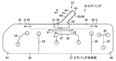
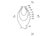
図5ないし図7において、10はエアバッグで、このエアバッグ10を備えたエアバッグ装置は、カーテンエアバッグ装置とも呼ばれるもので、車両である自動車の車体13の車室の収納位置としてのルーフサイド部15に配置されている。そして、このエアバッグ10は、カーテンエアバッグ、側突用エアバッグ、インフレータブルカーテン、あるいは頭部保護用エアバッグなどとも呼ばれるもので、側面衝突の衝撃を受けた際や横転(ロールオーバー)の際などに、被保護物としての乗員の側方にほぼ面状に展開し、乗員の頭部などを保護するようになっている。   5 to 7, reference numeral 10 denotes an airbag. The airbag apparatus provided with the airbag 10 is also called a curtain airbag apparatus, and is a roof as a housing position of a vehicle body 13 of an automobile, which is a vehicle. Arranged on the side portion 15. The airbag 10 is also called a curtain airbag, a side-impact airbag, an inflatable curtain, or a head protection airbag. The airbag 10 is subjected to a side impact or rollover. For example, it is deployed in a substantially planar manner on the side of the occupant as the object to be protected to protect the occupant's head and the like.

なお、以下、前後方向、車幅方向である両側方向、上下方向などの方向は、車両の直進方向を基準とし、前後方向(図7に示す矢印F,R方向)、上下方向(図7に示す矢印U,D方向)、車室の外方(図6に示す矢印W方向)、車室の内方(図6に示す矢印C方向)などを説明する。   In the following description, the front-rear direction, the vehicle width direction, both-side direction, the up-down direction, and the like are based on the straight traveling direction of the vehicle, and the front-rear direction (arrow F and R directions shown in FIG. 7) The direction of arrows U and D shown), the outside of the passenger compartment (the direction of arrow W shown in FIG. 6), the inner side of the passenger compartment (the direction of arrow C shown in FIG. 6), and the like will be described.

そして、この自動車の車体13は、車室内に乗員が着座可能な前席及び後席を備え、これら前席及び後席に対応して、それぞれ上部に開口可能な開口部としての窓部(サイドウィンドウ)18を備えた図示しないドアが設けられている。また、車室の両側には、前側から順に、Aピラーとも呼ばれるフロントピラー21、Bピラーとも呼ばれるセンターピラー22、Cピラーとも呼ばれるリアピラー23が設けられている。そして、これら窓部18、ドア及び各ピラー21,22,23により、車室の両側部に所定面24が構成されている。また、これらピラー21,22,23の上側、すなわち窓部18の一縁部である上縁部に、ルーフサイドレールなどとも呼ばれる被取付部材を構成する車体パネルが設けられ、この車体パネルを介して天井部としての天井パネルが支持されている。また、両側のフロントピラー21の前側にはフロントガラス(フロントウインドシールド)が設けられ、両側のリアピラー23の後側にはリアガラスが設けられている。そして、収納位置としてのルーフサイド部15は、天井パネルの両側の縁部の部分から、この縁部の部分といわば交差する方向に伸びるフロントピラー21及びリアピラー23のほぼ全長にかかる部分にまで設定され、これら天井パネルの縁部の部分とフロントピラー21及びリアピラー23とで仮想的に構成される弧の内側に、エアバッグ10が展開する所定面24が設定される。   The vehicle body 13 includes a front seat and a rear seat on which passengers can sit in a passenger compartment, and corresponding to the front seat and the rear seat, a window portion (side) that can be opened at the top. A door (not shown) having a window 18 is provided. Further, on both sides of the passenger compartment, a front pillar 21 called A pillar, a center pillar 22 called B pillar, and a rear pillar 23 called C pillar are provided in this order from the front side. The window 18, the door, and the pillars 21, 22, 23 form a predetermined surface 24 on both sides of the passenger compartment. Further, a vehicle body panel constituting a mounted member called a roof side rail or the like is provided on the upper side of these pillars 21, 22 and 23, that is, the upper edge portion which is one edge portion of the window portion 18. The ceiling panel as a ceiling part is supported. A front glass (front windshield) is provided on the front side of the front pillars 21 on both sides, and a rear glass is provided on the rear side of the rear pillars 23 on both sides. And the roof side part 15 as a storage position is set from the edge part on both sides of the ceiling panel to the part covering almost the entire length of the front pillar 21 and the rear pillar 23 extending in a direction intersecting with this edge part. A predetermined surface 24 on which the airbag 10 is deployed is set inside an arc virtually formed by the edge portion of the ceiling panel and the front pillar 21 and the rear pillar 23.

なお、ここで、センターピラー22とは、前後の端部のピラーではなく、展開したエアバッグ10に覆われるピラーを示す。また、車両の種類によっては、片側に例えば4本以上のピラーを備える場合があるが、前から3本目以後のピラーは、リアピラー23として説明する。   Here, the center pillar 22 is not a pillar at the front and rear ends but a pillar covered by the deployed airbag 10. Further, depending on the type of vehicle, for example, four or more pillars may be provided on one side, but the third and subsequent pillars from the front will be described as the rear pillar 23.

そして、エアバッグ装置は、前後の座席の乗員を保護可能な、いわゆる前後席用エアバッグであり、車体パネルとヘッドライニングとなどに囲まれたルーフサイド部15すなわち車体13のドア開口部の上縁に沿って細長く折り畳んで収納されたエアバッグ10と、後席の後方あるいは上方に収納されこのエアバッグ10にガスを供給するガス発生器である図示しないインフレータとなどを備えている。また、このエアバッグ装置は、必要に応じて、エアバッグ10を車体パネルに取り付ける金属板をプレス加工などして形成された取付ブラケット、折り畳んだエアバッグ10に沿って取り付けられて展開時にエアバッグ10を保護する樹脂製のプロテクタ、及び折り畳んだエアバッグ10の形状を保持する破断可能な筒状あるいは紐状の形状保持部材としてのスリーブ、エアバッグ10の前端部に連結された図示しないテザーベルトなどが備えられている。   The airbag device is a so-called front and rear seat airbag that can protect passengers in the front and rear seats, and is located on the roof side portion 15 surrounded by the vehicle body panel and the head lining, that is, on the door opening portion of the vehicle body 13. The airbag 10 is stored in an elongated shape along the edge, and an inflator (not shown) that is stored behind or above the rear seat and supplies gas to the airbag 10. In addition, this airbag device is attached to the mounting bracket formed by pressing a metal plate that attaches the airbag 10 to the vehicle body panel as needed, and the folded airbag 10 so that the airbag is deployed. A resin protector that protects the air bag 10, a sleeve as a breakable cylindrical or string-like shape holding member that holds the shape of the folded airbag 10, a tether belt (not shown) connected to the front end of the airbag 10, and the like Is provided.

そして、エアバッグ10は、単数あるいは複数の基布を組み合わせ、例えば1枚の基布を下端で折り返し、あるいは2枚の基布を重ねて接合して、扁平な袋状に形成されたエアバッグ本体部31と、このエアバッグ本体部31の内部に一部が配置されたガス供給部32とを備え、図示しない取付部を介して上縁部の複数箇所が車体13側に取り付けられて、例えば図8(a)に示すように細長く折り畳んだ状態で図7に示すルーフサイド部15に収納される。   The airbag 10 is formed by combining a single base fabric or a plurality of base fabrics, for example, folding back one base fabric at the lower end, or joining two base fabrics together to form a flat bag. A main body 31 and a gas supply part 32 partially disposed inside the airbag main body 31 are provided, and a plurality of upper edge portions are attached to the vehicle body 13 via an attachment portion (not shown) For example, as shown in FIG. 8A, it is housed in the roof side portion 15 shown in FIG.

図5に示すエアバッグ本体部31は、車室の内側に配置される内側の基布部と車体側である外側に配置される外側の基布部とが重ねられてエアバッグ接合部で接合されて構成され、流入した膨張ガスGにより膨張展開するように形成されている。このエアバッグ本体部31は、中空部である気室であり、ガス供給部32が配置されるガス案内部35と、このガス案内部35に対して連通する膨張部36とを備えている。   The airbag main body 31 shown in FIG. 5 has an inner base fabric portion arranged inside the passenger compartment and an outer base fabric portion arranged outside on the vehicle body side, and is joined at the airbag joint portion. And configured to expand and deploy by the inflated gas G that has flowed in. The airbag main body 31 is an air chamber that is a hollow portion, and includes a gas guide portion 35 in which a gas supply portion 32 is disposed, and an inflating portion 36 that communicates with the gas guide portion 35.

ガス案内部35は、エアバッグ本体部31の上縁部に沿って前後方向を長手方向として直線状に設けられ、すなわち前後方向を長手方向である軸方向として略水平な柱状に展開する。このガス案内部35は、エアバッグ本体部31の前端部から後端部に亘って形成されている。   The gas guide portion 35 is provided linearly along the upper edge portion of the airbag main body 31 with the front-rear direction as the longitudinal direction, that is, expands into a substantially horizontal columnar shape with the front-rear direction as the axial direction as the longitudinal direction. The gas guide portion 35 is formed from the front end portion to the rear end portion of the airbag main body portion 31.

また、膨張部36は、内部に形成された複数の線状の規制部である内側接合部38により接合されて複数に区画され、展開時の幅寸法などが規制されるとともに、ガス案内部35の前側に連通し展開時に前席の乗員の側方に対向して展開する前席保護部41、及びガス案内部35の後側に連通し展開時に後席の乗員の側方に対向して展開する後席保護部42などが形成されている。   Further, the inflating portion 36 is joined and divided into a plurality of inner joint portions 38 that are a plurality of linear restricting portions formed inside, and the width dimension at the time of deployment is restricted, and the gas guide portion 35 The front seat protection part 41 that extends in communication with the front side of the front seat and faces the side of the occupant in the front seat, and the rear side of the gas guide unit 35 that faces the side of the occupant in the rear seat A rear seat protection part 42 and the like are formed.

また、エアバッグ接合部は、例えば縫製、接着、あるいは縫製とシール手段との併用などにより略気密あるいは高度な気密に構成され、膨張部36の外周を接合する図示しない外側接合部、及び上記内側接合部38などを備えている。   In addition, the airbag joint portion is configured to be substantially airtight or highly airtight, for example, by sewing, bonding, or a combination of sewing and sealing means, and an outer joint portion (not shown) that joins the outer periphery of the inflating portion 36, and the inner side A joining portion 38 and the like are provided.

また、取付部は、例えば車体取付用の取付片であり、エアバッグ本体部31の上縁部の所定位置に複数形成されている。そして、取付部は、エアバッグ本体部31を構成する基布部と一体に形成され、例えば、内側の基布部と外側の基布部とを重ね縫着して形成されている。   Further, the attachment portion is, for example, an attachment piece for attaching the vehicle body, and a plurality of attachment portions are formed at predetermined positions on the upper edge portion of the airbag main body portion 31. The attachment portion is formed integrally with the base fabric portion constituting the airbag main body 31, and is formed, for example, by overlapping and sewing the inner base fabric portion and the outer base fabric portion.

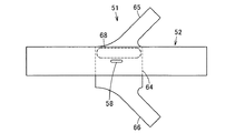
一方、図1及び図5に示すガス供給部32は、インナチューブなどとも呼ばれ、インフレータの接続管43が挿入接続される導入口44を一端に有するガス導入部としての管状の接続部45と、この接続部45に連通する管状の通路部である内側通路部46と、この内側通路部46の外部に位置する方向規制部である外側通路部47とを備えており、内側通路部46と外側通路部47とにより上下に二層の構造となっている。そして、このガス供給部32は、接続部45及び外側通路部47を形成する第1基布51と内側通路部46を形成する第2基布52とにより構成され、これら第1及び第2基布51,52が重ねられて基布接合部53により接合されて構成されている。   On the other hand, the gas supply section 32 shown in FIGS. 1 and 5 is also called an inner tube or the like, and has a tubular connection section 45 as a gas introduction section having an introduction port 44 into which an inflator connection pipe 43 is inserted and connected. An inner passage portion 46 that is a tubular passage portion that communicates with the connection portion 45, and an outer passage portion 47 that is a direction restricting portion located outside the inner passage portion 46. The outer passage portion 47 forms a two-layer structure on the top and bottom. The gas supply unit 32 includes a first base fabric 51 that forms the connecting portion 45 and the outer passage portion 47, and a second base fabric 52 that forms the inner passage portion 46, and the first and second base fabrics. The cloths 51 and 52 are overlapped and joined by a base cloth joining part 53.

接続部45は、前端部が内側通路部46と連通しており、後端部が内側通路部46と連通している。   The connection portion 45 has a front end portion communicating with the inner passage portion 46 and a rear end portion communicating with the inner passage portion 46.

また、内側通路部46は、導入口44から導入された膨張ガスGをエアバッグ本体部31の長手方向に沿って導くもので、エアバッグ本体部31の長手方向である前後方向に沿って長手状に形成されている。また、この内側通路部46は、前後両端部に一方及び他方の通気口55,56を有し、エアバッグ本体部31のガス案内部35内に収容されている。これら一方及び他方の通気口55,56は、ガス案内部35の前方及び後方に向けて延びており、ガス案内部35を介して膨張部36の前席保護部41及び後席保護部42と連通している。また、この内側通路部46の長手方向の中央部の下部には、外側通路部47と連通する連通口58が前後方向に沿って長孔状に開口されている。この連通口58は、導入口44から導入された膨張ガスGを外側通路部47へと出すもので、上下方向、すなわちエアバッグ本体部31の長手方向に交差(直交)する方向であるエアバッグ本体部31の短手方向に向けて開口している。   Further, the inner passage portion 46 guides the inflation gas G introduced from the introduction port 44 along the longitudinal direction of the airbag main body portion 31, and is elongated along the front-rear direction which is the longitudinal direction of the airbag main body portion 31. It is formed in a shape. Further, the inner passage portion 46 has one and other vent holes 55 and 56 at both front and rear end portions, and is accommodated in the gas guide portion 35 of the airbag main body portion 31. These one and the other vent holes 55 and 56 extend forward and rearward of the gas guide part 35, and through the gas guide part 35, the front seat protection part 41 and the rear seat protection part 42 of the expansion part 36 Communicate. Further, a communication port 58 communicating with the outer passage portion 47 is opened in a long hole shape along the front-rear direction at the lower portion of the center portion in the longitudinal direction of the inner passage portion 46. The communication port 58 is for discharging the inflation gas G introduced from the introduction port 44 to the outer passage portion 47, and is an airbag that is in a vertical direction, that is, a direction intersecting (orthogonal) with the longitudinal direction of the airbag body 31. The main body 31 opens toward the short side.

また、外側通路部47は、連通口58から内側通路部46の外部に出た膨張ガスGの流れを規制してエアバッグ本体部31の長手方向に沿って導くもので、前後方向、すなわちエアバッグ本体部31の長手方向に沿って長手状に形成されており、前後両端部に一方及び他方の外側通気口61,62を有し、内側通路部46とともにエアバッグ本体部31のガス案内部35内に収容されている。また、この外側通路部47は、本実施の形態において、内側通路部46よりも長手寸法が小さく設定されている。さらに、この外側通路部47は、連通口58に対向する位置において内側通路部46の外部に形成されている。したがって、この外側通路部47は、内側通路部46の長手方向の中央部を含む下部を覆って形成されている。   The outer passage portion 47 regulates the flow of the inflation gas G that has flowed out of the inner passage portion 46 from the communication port 58 and guides it along the longitudinal direction of the airbag body 31. It is formed in a longitudinal shape along the longitudinal direction of the bag body 31, has one and the other outer vents 61, 62 at both front and rear ends, and the gas guide part of the airbag body 31 together with the inner passage 46. Housed in 35. Further, the outer passage portion 47 is set to have a smaller longitudinal dimension than the inner passage portion 46 in the present embodiment. Further, the outer passage portion 47 is formed outside the inner passage portion 46 at a position facing the communication port 58. Therefore, the outer passage portion 47 is formed so as to cover a lower portion including the central portion in the longitudinal direction of the inner passage portion 46.

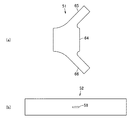
また、第1基布51は、図2(a)に示すように、外側通路部47を形成する四角形状の基布本体部64と、この基布本体部64の両側から傾斜状に突出し接続部45(図1)を形成する一方及び他方の接続部形成部65,66とを一体に備えている。   Further, as shown in FIG. 2A, the first base fabric 51 is connected to a quadrangular base fabric main body portion 64 that forms the outer passage portion 47 and an inclined projection from both sides of the base fabric main body portion 64. One and the other connecting portion forming portions 65 and 66 forming the portion 45 (FIG. 1) are integrally provided.

また、第2基布52は、図2(b)に示すように、第1基布51の基布本体部64よりも前後寸法すなわち長手寸法が大きい長方形状に形成されており、中央部に連通口58が長孔状に開口されている。   Further, as shown in FIG. 2 (b), the second base fabric 52 is formed in a rectangular shape having a longitudinal dimension, that is, a longitudinal dimension larger than that of the base fabric body portion 64 of the first base fabric 51, and is formed at the center portion. The communication port 58 is opened in a long hole shape.

さらに、図1に示すように、基布接合部53は、例えば縫製、接着、あるいは縫製とシール手段との併用などにより構成され、第1基布51の基布本体部64の両側と第2基布52の両側とを接合する一方及び他方の第1接合部68、及び第1基布51の一方及び他方の接続部形成部65,66ないし第2基布52を接合する線状の第2接合部69を備えている。   Further, as shown in FIG. 1, the base fabric joint portion 53 is configured by, for example, sewing, bonding, or a combination of sewing and sealing means, and the both sides of the base fabric main body portion 64 of the first base fabric 51 and the second base fabric portion 64. The first and second first joints 68 for joining the both sides of the base fabric 52, and the first and second connection part forming portions 65, 66 of the first base fabric 51 or the linear first joints for joining the second base fabric 52. Two joints 69 are provided.

そして、ガス供給部32を形成する際には、まず、図3に示すように、予め形成した第2基布52に対して、予め形成した第1基布51の基布本体部64を重ね、この基布本体部64の一側と第2基布52の一側とを一方の第1接合部68により接合する。   When forming the gas supply unit 32, first, as shown in FIG. 3, the base fabric body 64 of the first base fabric 51 is overlapped with the second base fabric 52 formed in advance. Then, one side of the base fabric main body 64 and one side of the second base fabric 52 are joined by one first joining portion 68.

次いで、図4に示すように、基布本体部64の他側と第2基布52の他側とを他方の第1接合部68により接合する。この状態で、第1基布51の基布本体部64と第2基布52との中央部がほぼ一致した状態となり、かつ、第1基布51の中央部が第2基布52に対して離間された状態となる。   Next, as shown in FIG. 4, the other side of the base fabric body portion 64 and the other side of the second base fabric 52 are joined by the other first joining portion 68. In this state, the center portion of the base fabric body portion 64 of the first base fabric 51 and the center portion of the second base fabric 52 are substantially aligned, and the center portion of the first base fabric 51 is in relation to the second base fabric 52. Separated.

そして、図1に示すように、第1基布51を第2基布52とともに折り曲げて一側と他側とを重ねるとともに一方及び他方の接続部形成部65,66を重ね、互いに重なり合った一方及び他方の接続部形成部65,66の前後の縁部から第2基布52の上側の縁部に亘ってそれぞれ第2接合部69により接合することで、ガス供給部32を完成する。   As shown in FIG. 1, the first base fabric 51 is folded together with the second base fabric 52 so that one side and the other side are overlapped, and one and the other connection portion forming portions 65 and 66 are overlapped, and the one overlapped with each other. And the gas supply part 32 is completed by joining by the 2nd junction part 69 from the edge part before and behind the other connection part formation parts 65 and 66 to the upper edge part of the 2nd base fabric 52, respectively.

また、エアバッグ10は、内側の基布部及び外側の基布部を重ねて平面状に広げた状態から、上記形成したガス供給部32を挟み込みつつエアバッグ本体部31を所定の細長い形状に折り畳み、エアバッグ接合部によって接合することで組み立てる。   In addition, the airbag 10 is formed in a predetermined elongated shape while sandwiching the formed gas supply part 32 from a state in which the inner base cloth part and the outer base cloth part are overlapped and spread in a planar shape. It is assembled by folding and joining by the airbag joint.

このエアバッグ10の折畳方法は、種々の方法を採ることができるが、例えば下側部をロール状に折り畳むとともに、上側部をパラソル状に折り畳む。   The airbag 10 can be folded by various methods. For example, the lower side portion is folded in a roll shape and the upper side portion is folded in a parasol shape.

そして、このエアバッグ装置(カーテンエアバッグモジュール)を車室内に持ち込み、ヘッドライニング及びピラーガーニッシュなどの内装部材が取り付けられる前に車体13への取付作業を行う。この取付作業は、エアバッグ10の複数の取付部、テザーベルト、インフレータに設けたインフレータ取付部、及び、取付ブラケットをそれぞれボルトなどの固定具で車体に固定することにより行われる。また、インフレータから導出されたハーネスを車体13に備えた制御装置に接続する。次いで、車体13の天井パネルにヘッドライニングを取り付け、各ピラー21,22,23にピラーガーニッシュを取り付けてエアバッグ装置を覆うことにより、エアバッグ装置の車体13への取付作業、すなわち、折り畳んだエアバッグ10を所定面24の上縁部に沿った収納位置であるルーフサイド部15に配置する作業が完了する。   Then, the airbag device (curtain airbag module) is brought into the vehicle interior, and is attached to the vehicle body 13 before the interior members such as the head lining and the pillar garnish are attached. This attachment work is performed by fixing the plurality of attachment portions of the airbag 10, the tether belt, the inflator attachment portions provided on the inflator, and the attachment brackets to the vehicle body with fixing tools such as bolts. Further, the harness derived from the inflator is connected to a control device provided in the vehicle body 13. Next, the headlining is attached to the ceiling panel of the vehicle body 13, and the pillar garnish is attached to each pillar 21, 22, and 23 to cover the airbag device, so that the airbag device is attached to the vehicle body 13, that is, the folded air The operation of placing the bag 10 on the roof side portion 15 that is the storage position along the upper edge portion of the predetermined surface 24 is completed.

次に、エアバッグ10の展開動作を説明する。   Next, a deployment operation of the airbag 10 will be described.

車両の側面衝突あるいは横転などの際には、制御装置によりインフレータが作動し、このインフレータから噴射される膨張ガスGが接続管43を介し導入口44からガス供給部32内へと導入される。   In the event of a side collision or rollover of the vehicle, the inflator is actuated by the control device, and the inflation gas G injected from the inflator is introduced from the inlet 44 into the gas supply unit 32 via the connection pipe 43.

この導入された膨張ガスGは、接続部45を通過して内側通路部46内へと流入し、この内側通路部46に沿って一部が前方及び後方へとガイドされるとともに、残りの他部が連通口58から内側通路部46の下方へと出る。   The introduced expansion gas G passes through the connection portion 45 and flows into the inner passage portion 46, and a part of the inflation gas G is guided forward and rearward along the inner passage portion 46, and the remaining other The part exits from the communication port 58 to the lower side of the inner passage part 46.

内側通路部46に沿って前方及び後方へとガイドされた膨張ガスGは、内側通路部46の一方及び他方の通気口55,56からエアバッグ本体部31の長手方向に沿ってガス案内部35へと出る。この結果、ガス案内部35が長手方向全体、すなわち前端部から後端部に亘って均一、あるいは略均一に迅速に膨張展開して、ヘッドライニング及び前後のピラーガーニッシュを押しのける。   The inflation gas G guided forward and rearward along the inner passage portion 46 extends from the one and the other vent holes 55 and 56 of the inner passage portion 46 along the longitudinal direction of the airbag main body 31. Go out. As a result, the gas guide portion 35 rapidly expands and deploys uniformly or substantially uniformly over the entire longitudinal direction, that is, from the front end portion to the rear end portion, and pushes out the head lining and the front and rear pillar garnishes.

一方、連通口58から内側通路部46の下方へと出た膨張ガスGは、外側通路部47内へと下方に向けて流入し、この外側通路部47を構成する第1基布51に衝突することで、この外側通路部47に沿って前方及び後方へとガイドされ、一方及び他方の外側通気口61,62からエアバッグ本体部31の長手方向に沿ってガス案内部35へと出て、膨張部36(前席保護部41及び後席保護部42)に導入される。この結果、膨張部36が車室の側部内面である所定面24をこすりながら巻き戻されるように所定面24に沿った所定方向である略下方に迅速にカーテン状に膨張展開して(図8(b))、図7に示す窓部18及びセンターピラー22などを覆う。この状態で、エアバッグ10は側方に投げ出されてくる乗員を拘束してその頭部などを保護する。   On the other hand, the expansion gas G that has flowed out from the communication port 58 to the lower side of the inner passage portion 46 flows downward into the outer passage portion 47 and collides with the first base cloth 51 constituting the outer passage portion 47. As a result, it is guided forward and rearward along the outer passage portion 47, and exits from one and the other outer vents 61 and 62 to the gas guide portion 35 along the longitudinal direction of the airbag main body 31. Then, it is introduced into the expansion part 36 (the front seat protection part 41 and the rear seat protection part 42). As a result, the inflating portion 36 is rapidly inflated and deployed in a curtain shape substantially downward in a predetermined direction along the predetermined surface 24 so as to be rewound while rubbing the predetermined surface 24 that is the inner side surface of the passenger compartment (see FIG. 8 (b)), covering the window 18 and the center pillar 22 shown in FIG. In this state, the airbag 10 restrains the occupant thrown out to the side and protects its head and the like.

このように、本実施の形態によれば、内側通路部46によってエアバッグ本体部31の長手方向に膨張ガスGを導くことにより、エアバッグ本体部31の長手方向両端に膨張ガスGを確実に供給して、長尺なエアバッグ本体部31を瞬時に所定の位置に円滑に展開させることができるとともに、ガス供給部32の内側通路部46にエアバッグ本体部31の長手方向と交差(直交)する方向に向けて連通口58を設け、連通口58に対向する外側通路部47によって膨張ガスGの一部の流れ方向を規制することで連通口58を介してエアバッグ本体部31内に供給される膨張ガスGのエアバッグ本体部31の長手方向と交差(直交)する方向への流れを低減することにより、膨張ガスGの圧力がエアバッグ本体部31の膨張部36に対してこのエアバッグ本体部31の長手方向と交差(直交)する短手方向に直接作用することがなく、エアバッグ本体部31、すなわちエアバッグ本体部31を構成する基布部を保護できる。   As described above, according to the present embodiment, the inflation gas G is reliably guided to both ends in the longitudinal direction of the airbag body 31 by guiding the inflation gas G in the longitudinal direction of the airbag body 31 by the inner passage portion 46. The long air bag main body 31 can be smoothly deployed to a predetermined position instantly, and the inner passage portion 46 of the gas supply section 32 intersects with the longitudinal direction of the air bag main body 31 (orthogonal). ) A communication port 58 is provided in the direction of the air flow, and the flow direction of a part of the inflation gas G is regulated by the outer passage portion 47 facing the communication port 58, so that the airbag main body 31 is connected to the airbag 31 through the communication port 58. By reducing the flow of the supplied inflation gas G in the direction intersecting (orthogonal) with the longitudinal direction of the airbag body 31, the pressure of the inflation gas G is applied to the inflation portion 36 of the airbag body 31. Intersects with the longitudinal direction of the airbag body 31 (orthogonal) Without having to act directly in the lateral direction of the airbag body 31, namely to protect the base fabric portions constituting the airbag body portion 31.

また、外側通路部47の少なくとも一部を連通口58に対向させて内側通路部46の外部に配置して、連通口58から内側通路部46の外部に出た膨張ガスGをエアバッグ本体部31の長手方向に導くことにより、内側通路部46と外側通路部47との二層構造によって、連通口58から出た膨張ガスGが直接エアバッグ本体部31に晒されることがなく、連通口58から内側通路部46の外部に出た膨張ガスGのエアバッグ本体部の長手方向と交差(直交)する短手方向への流れをより確実に低減できる。   Further, at least a part of the outer passage portion 47 is disposed outside the inner passage portion 46 so as to face the communication port 58, and the inflation gas G that has flowed out of the inner passage portion 46 from the communication port 58 is removed from the airbag main body portion. By leading in the longitudinal direction of 31, the two-layer structure of the inner passage portion 46 and the outer passage portion 47 prevents the inflation gas G from the communication port 58 from being directly exposed to the airbag body 31, and the communication port It is possible to more reliably reduce the flow of the inflation gas G that has flowed out of the inner passage portion 46 from 58 in the short direction intersecting (orthogonal) with the longitudinal direction of the airbag main body portion.

そして、エアバッグ本体部31の外郭を構成する基布と同一、あるいは同等の2枚の基布を用い、第2基布52の連通口58を覆って第1基布51を縫着する簡単な構成によりガス供給部32を製造できるので、製造コストを低減できる。   Then, two base cloths that are the same as or equivalent to the base cloth constituting the outer shell of the airbag main body 31 are used, and the first base cloth 51 is sewn by covering the communication port 58 of the second base cloth 52. Since the gas supply unit 32 can be manufactured with a simple configuration, the manufacturing cost can be reduced.

次に、第2の実施の形態を図9及び図10を参照して説明する。なお、上記第1の実施の形態と同様の構成及び作用については、同一符号を付してその説明を省略する。   Next, a second embodiment will be described with reference to FIGS. In addition, about the structure and effect | action similar to the said 1st Embodiment, the same code | symbol is attached | subjected and the description is abbreviate | omitted.

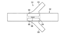
この第2の実施の形態は、上記第1の実施の形態のガス供給部32が、接続部45及び内側通路部46を形成する第1基布71と外側通路部47を形成する第2基布72とにより構成され、これら第1及び第2基布71,72が重ねられて基布接合部73により接合されて構成されているものである。   In the second embodiment, the gas supply section 32 of the first embodiment is configured such that the first base cloth 71 that forms the connection section 45 and the inner passage section 46 and the second base section that forms the outer passage section 47. The first and second base fabrics 71 and 72 are overlapped and joined by a base fabric joining portion 73.

すなわち、第1基布71は、図10に示すように、前後方向に長手状で内側通路部46(図9)を形成する長方形状の内側通路部形成部75と、この内側通路部形成部75から突出し接続部45(図9)を形成する一方及び他方の接続部形成部76,77とを一体に備えている。そして、内側通路部形成部75には、連通口58が形成されている。   That is, as shown in FIG. 10, the first base fabric 71 includes a rectangular inner passage portion forming portion 75 that is long in the front-rear direction and forms the inner passage portion 46 (FIG. 9), and the inner passage portion forming portion. One and the other connecting portion forming portions 76 and 77 that project from 75 and form the connecting portion 45 (FIG. 9) are integrally provided. A communication port 58 is formed in the inner passage portion forming portion 75.

また、第2基布72は、前後方向に長手状の四角形状に形成されている。この第2基布72は、第1基布71に対して前後方向の寸法が小さく設定されている。   The second base fabric 72 is formed in a rectangular shape that is long in the front-rear direction. The second base fabric 72 is set to have a smaller size in the front-rear direction than the first base fabric 71.

さらに、図9に示すように、基布接合部73は、例えば縫製、接着、あるいは縫製とシール手段との併用などにより構成され、第1基布71の内側通路部形成部75と第2基布72とを接合する線状の第1接合部78、及び第1基布71の接続部形成部76,77ないし内側通路部形成部75を接合する線状の第2接合部79を備えている。   Further, as shown in FIG. 9, the base fabric joint portion 73 is configured by, for example, sewing, bonding, or a combination of sewing and sealing means, and the inner passage portion forming portion 75 and the second base portion of the first base fabric 71. A linear first joint portion 78 for joining the cloth 72 and a linear second joint portion 79 for joining the connection portion forming portions 76 and 77 of the first base fabric 71 or the inner passage portion forming portion 75 are provided. Yes.

そして、ガス供給部32を形成する際には、まず、図10(a)に示すように、予め形成した第1基布71の内側通路部形成部75の連通口58を覆うように第2基布72を重ねる。次いで、図10(b)に示すように、第1基布71の内側通路部形成部75の一側及び他側と第2基布72の一側及び他側とを、それぞれ第1接合部78により接合する。さらに、図10(c)に示すように、第1基布71を第2基布72とともに折り曲げて一側と他側とを重ね、互いに重なり合った一方及び他方の接続部形成部76,77の前後の縁部から内側通路部形成部75の上側の縁部に亘ってそれぞれ第2接合部79により接合することで、ガス供給部32を完成する。   Then, when forming the gas supply part 32, first, as shown in FIG. 10A, a second so as to cover the communication port 58 of the inner passage part forming part 75 of the first base cloth 71 formed in advance. Overlay the base fabric 72. Next, as shown in FIG. 10 (b), one side and the other side of the inner passage portion forming portion 75 of the first base fabric 71 and one side and the other side of the second base fabric 72 are respectively connected to the first joint portion. Join by 78. Further, as shown in FIG. 10 (c), the first base cloth 71 is bent together with the second base cloth 72 so that one side and the other side are overlapped, and the one and the other connecting portion forming portions 76 and 77 overlap each other. The gas supply section 32 is completed by joining the front and rear edges to the upper edge of the inner passage section forming section 75 by the second joint section 79.

このように構成したガス供給部32を備えるエアバッグ10は、上記第1の実施の形態と同様に、インフレータからの膨張ガスGが接続管43を介し導入口44からガス供給部32内へと導入されると、この導入された膨張ガスGが、接続部45を通過して内側通路部46内へと流入し、この内側通路部46に沿って一部が前方及び後方へとガイドされて一方及び他方の通気口55,56からエアバッグ本体部31の長手方向に沿ってガス案内部35へと出て、ガス案内部35を長手方向全体、すなわち前端部から後端部に亘って均一、あるいは略均一に迅速に膨張展開させる。また、残りの膨張ガスGは、連通口58から内側通路部46の下方へと出て外側通路部47内に流入し、この外側通路部47を構成する第2基布72に衝突することで、この外側通路部47に沿って前方及び後方へとガイドされ、一方及び他方の外側通気口61,62からエアバッグ本体部31の長手方向に沿ってガス案内部35へと出て、膨張部36(前席保護部41及び後席保護部42)を所定面24に沿った下方に迅速にカーテン状に膨張展開させる。   In the airbag 10 including the gas supply unit 32 configured as described above, the inflation gas G from the inflator is transferred from the introduction port 44 into the gas supply unit 32 via the connection pipe 43, as in the first embodiment. When introduced, the introduced expansion gas G passes through the connection portion 45 and flows into the inner passage portion 46, and a part of the inflation gas G is guided forward and rearward along the inner passage portion 46. The gas guide part 35 exits from the one and the other vent holes 55 and 56 to the gas guide part 35 along the longitudinal direction of the airbag main body 31, and the gas guide part 35 is uniform over the entire longitudinal direction, that is, from the front end to the rear end. Or, it is inflated and deployed almost uniformly and rapidly. Further, the remaining inflation gas G exits from the communication port 58 to the lower side of the inner passage portion 46 and flows into the outer passage portion 47, and collides with the second base fabric 72 constituting the outer passage portion 47. Then, it is guided forward and rearward along the outer passage portion 47, and exits from the one and the other outer vents 61 and 62 to the gas guide portion 35 along the longitudinal direction of the airbag main body 31, and the inflating portion. 36 (the front seat protection part 41 and the rear seat protection part 42) is rapidly inflated and deployed in a curtain shape downward along the predetermined surface 24.

このように上記第2の実施の形態によれば、内側通路部46によってエアバッグ本体部31の長手方向に膨張ガスGを導くことにより、エアバッグ本体部31の長手方向両端に膨張ガスGを確実に供給して、長尺なエアバッグ本体部31を瞬時に所定の位置に円滑に展開させることができるとともに、ガス供給部32の内側通路部46にエアバッグ本体部31の長手方向と交差(直交)する方向に向けて連通口58を設け、連通口58に対向する外側通路部47によって膨張ガスGの一部の流れ方向を規制することで連通口58を介してエアバッグ本体部31内に供給される膨張ガスGのエアバッグ本体部31の長手方向と交差(直交)する方向への流れを低減することにより、膨張ガスGの圧力がエアバッグ本体部31の膨張部36に対してこのエアバッグ本体部31の長手方向と交差(直交)する短手方向に直接作用することがなく、エアバッグ本体部31、すなわちエアバッグ本体部31を構成する基布部を保護できるなど、上記第1の実施の形態と同様の作用効果を奏することができる。   As described above, according to the second embodiment, the inflation gas G is introduced into the longitudinal ends of the airbag body 31 by guiding the inflation gas G in the longitudinal direction of the airbag body 31 by the inner passage portion 46. The air bag body 31 can be surely supplied and the long air bag main body 31 can be instantly and smoothly deployed at a predetermined position, and the inner passage portion 46 of the gas supply section 32 intersects the longitudinal direction of the air bag main body 31. A communication port 58 is provided in a (perpendicular) direction, and a part of the flow direction of the inflation gas G is regulated by the outer passage portion 47 facing the communication port 58, whereby the airbag body 31 is connected via the communication port 58. By reducing the flow of the inflation gas G supplied into the airbag body 31 in the direction intersecting (orthogonal to) the longitudinal direction of the airbag body portion 31, the pressure of the inflation gas G is applied to the inflation portion 36 of the airbag body portion 31. Crosses the longitudinal direction of the lever body 31 of the lever The effect similar to that of the first embodiment, such as protection of the airbag main body 31, that is, the base fabric part constituting the airbag main body 31, does not directly act in the transverse direction that is orthogonal. Can play.

なお、上記第2の実施の形態において、図11に示す第3の実施の形態のように、ガス供給部32に連通口58を複数設け、これら連通口58のそれぞれに外側通路部47を形成してもよい。この場合には、各連通口58から出る膨張ガスGの流れをより確実に分散してエアバッグ本体部31内に供給でき、エアバッグ本体部31、すなわちエアバッグ本体部31を構成する基布部をより確実に保護できる。   In the second embodiment, as in the third embodiment shown in FIG. 11, a plurality of communication ports 58 are provided in the gas supply unit 32, and an outer passage portion 47 is formed in each of these communication ports 58. May be. In this case, the flow of the inflation gas G exiting from each communication port 58 can be more reliably dispersed and supplied into the airbag main body 31, and the airbag main body 31, that is, the base fabric constituting the airbag main body 31 The part can be protected more reliably.

次に、第4の実施の形態を図12を参照して説明する。なお、上記各実施の形態と同様の構成及び作用については、同一符号を付してその説明を省略する。   Next, a fourth embodiment will be described with reference to FIG. In addition, about the structure and effect | action similar to said each embodiment, the same code | symbol is attached | subjected and the description is abbreviate | omitted.

この第4の実施の形態のエアバッグ10は、上記第2の実施の形態のガス供給部32の第2基布72が、第1基布71よりも前後方向、すなわちエアバッグ本体部31の長手方向の寸法が大きいものである。   In the airbag 10 of the fourth embodiment, the second base fabric 72 of the gas supply unit 32 of the second embodiment is in the front-rear direction relative to the first base fabric 71, that is, the airbag main body 31 The dimension in the longitudinal direction is large.

すなわち、第2基布72は、第1基布71の内側通路部形成部75よりも前後方向への長手寸法が大きい長方形状に形成されている。   That is, the second base fabric 72 is formed in a rectangular shape having a longer longitudinal dimension in the front-rear direction than the inner passage portion forming portion 75 of the first base fabric 71.

そして、第1基布71と第2基布72とを接合する基布接合部73は、第1基布71の内側通路部形成部75と第2基布72とを接合する第1接合部78の他に、第1基布71の接続部形成部76,77と第2基布72とを接合する線状の第2接合部81を備えている。   And the base fabric joint part 73 which joins the 1st base fabric 71 and the 2nd base fabric 72 is the 1st joint part which joins the inner side channel | path part formation part 75 and the 2nd base fabric 72 of the 1st base fabric 71. In addition to 78, a linear second joint portion 81 for joining the connection portion forming portions 76 and 77 of the first base fabric 71 and the second base fabric 72 is provided.

ガス供給部32を形成する際には、まず、予め形成した第2基布72に対して、予め形成した第1基布71の内側通路部形成部75を、第2基布72の中央部に連通口58が位置するように重ね、第1基布71の内側通路部形成部75の一側及び他側と第2基布72の一側及び他側とを、それぞれ第1接合部78により接合し、さらに、第1基布71と第2基布72とをともに折り曲げて一側と他側とを重ね、互いに重なり合った一方及び他方の接続部形成部76,77の前後の縁部から第2基布72の上側の縁部に亘ってそれぞれ第2接合部81により接合することで、ガス供給部32を完成する。   When forming the gas supply section 32, first, the inner passage section forming section 75 of the first base cloth 71 formed in advance with respect to the second base cloth 72 formed in advance is replaced with the center section of the second base cloth 72. And the one side and the other side of the inner passage portion forming portion 75 of the first base fabric 71 and the one side and the other side of the second base fabric 72 are respectively connected to the first joint portion 78. Further, the first base cloth 71 and the second base cloth 72 are bent together so that one side and the other side are overlapped, and the front and rear edge portions of the one and the other connection portion forming portions 76 and 77 that overlap each other The gas supply section 32 is completed by joining the upper edge of the second base fabric 72 with the second joint 81 respectively.

そして、このように構成したガス供給部32を備えるエアバッグ10は、インフレータからの膨張ガスGが接続管43を介し導入口44からガス供給部32内へと導入されると、この導入された膨張ガスGが、接続部45を通過して内側通路部46内へと流入し、この内側通路部46に沿って一部が前方及び後方へとガイドされるとともに、残りの他部が連通口58から内側通路部46の下方へと出る。そして、この連通口58から内側通路部46の下方へと出た膨張ガスGは、外側通路部47内へと下方に向けて流入し、この外側通路部47を構成する第2基布72に衝突することで、この外側通路部47に沿って前方及び後方へとガイドされる。したがって、エアバッグ本体部31は、内側通路部46に沿って前方及び後方へとガイドされて一方及び他方の通気口55,56から内側通路部46の外部に出た膨張ガスGと、連通口58から内側通路部46の外部に出た膨張ガスGとが、それぞれ外側通路部47に沿ってガイドされて一方及び他方の外側通気口61,62からエアバッグ本体部31の長手方向に沿ってガス案内部35に出ることにより、ガス案内部35が長手方向全体、すなわち前端部から後端部に亘って均一、あるいは略均一に迅速に膨張展開する。この後、ガス案内部35から膨張ガスGが導入された膨張部36(前席保護部41及び後席保護部42)が所定面24に沿った下方に迅速にカーテン状に膨張展開する。   The airbag 10 including the gas supply unit 32 configured as described above is introduced when the inflation gas G from the inflator is introduced into the gas supply unit 32 from the introduction port 44 through the connection pipe 43. The expansion gas G passes through the connecting portion 45 and flows into the inner passage portion 46, a part of which is guided forward and rearward along the inner passage portion 46, and the remaining portion is a communication port. 58 exits below the inner passage 46. The expansion gas G that has flowed out from the communication port 58 to the lower side of the inner passage portion 46 flows downward into the outer passage portion 47, and enters the second base fabric 72 constituting the outer passage portion 47. By colliding, it is guided forward and backward along the outer passage portion 47. Accordingly, the airbag main body 31 is guided to the front and rear along the inner passage portion 46 and communicates with the inflation gas G that has flowed out of the inner passage portion 46 from one and the other vent holes 55 and 56. The inflation gas G that has flowed out of the inner passage portion 46 from 58 is guided along the outer passage portion 47, and from the one and the other outer vents 61, 62 along the longitudinal direction of the airbag body 31. By exiting to the gas guide part 35, the gas guide part 35 rapidly and uniformly expands and deploys uniformly or substantially uniformly from the entire longitudinal direction, that is, from the front end part to the rear end part. Thereafter, the expansion part 36 (the front seat protection part 41 and the rear seat protection part 42) into which the expansion gas G has been introduced from the gas guide part 35 is rapidly inflated and deployed in a curtain shape downward along the predetermined surface 24.

このように、上記第4の実施の形態によれば、内側通路部46によってエアバッグ本体部31の長手方向に膨張ガスGを導くことにより、外側通路部47を介してエアバッグ本体部31の長手方向両端に膨張ガスGを確実に供給して、長尺なエアバッグ本体部31を瞬時に所定の位置に円滑に展開させることができるとともに、ガス供給部32の内側通路部46にエアバッグ本体部31の長手方向と交差(直交)する方向に向けて連通口58を設け、連通口58に対向する外側通路部47によって膨張ガスGの一部の流れ方向を規制することで連通口58を介してエアバッグ本体部31内に供給される膨張ガスGのエアバッグ本体部31の長手方向と交差(直交)する方向への流れを低減することにより、膨張ガスGの圧力がエアバッグ本体部31の膨張部36に対してこのエアバッグ本体部31の長手方向と交差(直交)する短手方向に直接作用することがなく、エアバッグ本体部31、すなわちエアバッグ本体部31を構成する基布部を保護できるなど、上記各実施の形態と同様の作用効果を奏することができる。   As described above, according to the fourth embodiment, the inflation gas G is guided in the longitudinal direction of the airbag main body 31 by the inner passage portion 46, whereby the airbag main body portion 31 of the airbag main body portion 31 is interposed via the outer passage portion 47. The inflation gas G can be reliably supplied to both ends in the longitudinal direction so that the long airbag body 31 can be instantly and smoothly deployed at a predetermined position, and the airbag can be connected to the inner passage portion 46 of the gas supply section 32. A communication port 58 is provided in a direction intersecting (orthogonal) with the longitudinal direction of the main body portion 31, and a flow direction of a part of the expansion gas G is regulated by the outer passage portion 47 facing the communication port 58. The pressure of the inflation gas G is reduced by reducing the flow of the inflation gas G supplied into the airbag body 31 via the cross section in a direction intersecting (orthogonal) with the longitudinal direction of the airbag body 31. This airbag book against the inflating part 36 of the part 31 Each of the above-described embodiments, such as protecting the airbag main body 31, that is, the base fabric constituting the airbag main body 31, without directly acting in the short direction intersecting (orthogonal) with the longitudinal direction of the portion 31. The same operational effects can be achieved.

次に、第5の実施の形態を図13を参照して説明する。なお、上記各実施の形態と同様の構成及び作用については、同一符号を付してその説明を省略する。   Next, a fifth embodiment will be described with reference to FIG. In addition, about the structure and effect | action similar to said each embodiment, the same code | symbol is attached | subjected and the description is abbreviate | omitted.

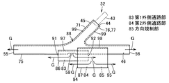
この第5の実施の形態のエアバッグ10は、上記各実施の形態の外側通路部47に代えて、ガス供給部32が第1外側通路部83と第2外側通路部84とを有する方向規制部85を備えているものである。そして、このガス供給部32は、第1基布71と、第1外側通路部83を形成する第2基布86と、第2外側通路部84を形成する第3基布87とを備え、これら基布71,86,87が基布接合部88により接合されて構成されている。   In the airbag 10 of the fifth embodiment, the gas supply unit 32 includes a first outer passage portion 83 and a second outer passage portion 84 in place of the outer passage portion 47 of each of the above embodiments. A portion 85 is provided. And this gas supply part 32 is provided with the 1st base cloth 71, the 2nd base cloth 86 which forms the 1st outside passage part 83, and the 3rd base cloth 87 which forms the 2nd outside passage part 84, These base fabrics 71, 86, and 87 are joined by a base fabric joint portion 88.

第1外側通路部83は、連通口58から出た膨張ガスGの流れを規制してエアバッグ本体部31の長手方向に沿って導くもので、前後方向、すなわちエアバッグ本体部31の長手方向に沿って長手状に形成されており、前後両端部に一方及び他方の第1外側通気口91,92を有し、内側通路部46とともにエアバッグ本体部31のガス案内部35内に収容されている。また、この第1外側通路部83は、本実施の形態において、内側通路部46よりも長手寸法が小さく設定されている。さらに、この第1外側通路部83は、連通口58に対向する位置において内側通路部46の外部に形成されている。したがって、この第1外側通路部83は、内側通路部46の長手方向の中央部を含む下部を覆って形成されている。   The first outer passage portion 83 regulates the flow of the inflation gas G exiting from the communication port 58 and guides it along the longitudinal direction of the airbag main body portion 31. And has first and second first outer vents 91 and 92 at both front and rear ends, and is accommodated in the gas guide portion 35 of the airbag main body 31 together with the inner passage portion 46. ing. The first outer passage portion 83 is set to have a smaller longitudinal dimension than the inner passage portion 46 in the present embodiment. Further, the first outer passage portion 83 is formed outside the inner passage portion 46 at a position facing the communication port 58. Therefore, the first outer passage portion 83 is formed so as to cover the lower portion including the central portion of the inner passage portion 46 in the longitudinal direction.

また、第2外側通路部84は、第1外側通路部83の長手方向の一端部、本実施の形態では後端部の他方の第1外側通気口92から第1外側通路部83の外部に出た膨張ガスGの流れを規制してエアバッグ本体部31の長手方向に沿ってさらに導くもので、前後方向、すなわちエアバッグ本体部31の長手方向に沿って長手状に形成されており、前後両端部に一方及び他方の第2外側通気口94,95を有し、内側通路部46及び第1外側通路部83とともにエアバッグ本体部31のガス案内部35内に収容されている。また、この第2外側通路部84は、本実施の形態において、内側通路部46よりも長手寸法が小さく設定されている。さらに、この第2外側通路部84は、第1外側通路部83の外部に形成されており、この第1の外側通路部83の後端部よりも前方に一方の第2外側通気口94が位置し、第1の外側通路部83の後端部よりも後方に他方の第2外側通気口95が位置している。すなわち、この第2外側通路部84は、第1外側通路部83の後端部の下方に沿って前端側の一部が位置している。換言すれば、本実施の形態のガス供給部32は、内側通路部46と、第1外側通路部83と第2外側通路部84とにより、上下に三層構造となっている。   In addition, the second outer passage portion 84 extends from one end portion in the longitudinal direction of the first outer passage portion 83, in the present embodiment, from the other first outer vent 92 at the rear end portion to the outside of the first outer passage portion 83. It regulates the flow of the inflation gas G that has come out and further guides it along the longitudinal direction of the airbag body 31, and is formed in a longitudinal shape along the longitudinal direction, that is, the longitudinal direction of the airbag body 31, One and the other second outer vents 94 and 95 are provided at both the front and rear ends, and are accommodated in the gas guide portion 35 of the airbag main body 31 together with the inner passage portion 46 and the first outer passage portion 83. The second outer passage portion 84 is set to have a smaller longitudinal dimension than the inner passage portion 46 in the present embodiment. Further, the second outer passage portion 84 is formed outside the first outer passage portion 83, and one second outer vent 94 is located in front of the rear end portion of the first outer passage portion 83. The other second outer vent 95 is located behind the rear end portion of the first outer passage portion 83. That is, a part of the front end side of the second outer passage portion 84 is located below the rear end portion of the first outer passage portion 83. In other words, the gas supply unit 32 of the present embodiment has a three-layer structure in the vertical direction by the inner passage portion 46, the first outer passage portion 83, and the second outer passage portion 84.

また、第2及び第3の基布86,87は、それぞれ前後方向に長手状の四角形状に形成されている。これら第2及び第3の基布86,87は、第1基布71に対してそれぞれ前後方向の寸法が小さく設定されている。   The second and third base fabrics 86 and 87 are each formed in a rectangular shape that is long in the front-rear direction. These second and third base fabrics 86 and 87 are set to have smaller dimensions in the front-rear direction than the first base fabric 71.

また、基布接合部88は、例えば縫製、接着、あるいは縫製とシール手段との併用などにより構成され、第1基布71の内側通路部形成部75と第2基布86とを接合する線状の第1接合部97、第1基布71の内側通路部形成部75と第3基布87とを接合する線状の第2接合部98、及び第1基布71の接続部形成部76,77ないし内側通路部形成部75を接合する線状の第3接合部99を備えている。   Further, the base fabric joint portion 88 is configured by, for example, sewing, bonding, or a combination of sewing and sealing means, and is a line that joins the inner passage portion forming portion 75 of the first base fabric 71 and the second base fabric 86. First joint portion 97, linear second joint portion 98 for joining inner passage portion forming portion 75 of first base fabric 71 and third base fabric 87, and connection portion forming portion for first base fabric 71 76 and 77 or the linear 3rd junction part 99 which joins the inner side channel | path part formation part 75 is provided.

そして、ガス供給部32を形成する際には、まず、予め形成した第1基布71の内側通路部形成部75の連通口58を覆うように第2基布86を重ね、第1基布71の内側通路部形成部75の一側及び他側と第2基布72の一側及び他側とを、それぞれ第1接合部97により接合し、さらに、第2基布86の長手方向の一端側、本実施の形態では後側を覆って、第1基布71の内側通路部形成部75の一側及び他側と第3基布87の一側及び他側とを第2接合部98により接合し、かつ、第1、第2及び第3基布71,86,87をともに折り曲げて一側と他側とを重ね、互いに重なり合った一方及び他方の接続部形成部76,77の前後の縁部から内側通路部形成部75の上側の縁部に亘ってそれぞれ第3接合部99により接合することで、ガス供給部32を完成する。   When forming the gas supply part 32, first, the second base cloth 86 is overlaid so as to cover the communication port 58 of the inner passage part forming part 75 of the first base cloth 71 formed in advance. One side and the other side of the inner passage portion forming portion 75 of the 71 and one side and the other side of the second base fabric 72 are joined by the first joint portion 97, respectively, and further, in the longitudinal direction of the second base fabric 86 One end side, the rear side in the present embodiment is covered, and one side and the other side of the inner passage portion forming portion 75 of the first base fabric 71 and one side and the other side of the third base fabric 87 are connected to the second joint portion. 98, and the first, second and third base fabrics 71, 86 and 87 are bent together so that one side and the other side are overlapped. The gas supply section 32 is completed by joining the front and rear edges to the upper edge of the inner passage portion forming portion 75 by the third joint portions 99, respectively.

このように構成したガス供給部32を備えるエアバッグ10は、インフレータからの膨張ガスGが接続管43を介し導入口44からガス供給部32内へと導入されると、この導入された膨張ガスGが、接続部45を通過して内側通路部46内へと流入し、この内側通路部46に沿って一部が前方及び後方へとガイドされて一方及び他方の通気口55,56からエアバッグ本体部31の長手方向に沿ってガス案内部35へと出て、ガス案内部35を長手方向全体、すなわち前端部から後端部に亘って均一、あるいは略均一に迅速に膨張展開させる。また、残りの膨張ガスGは、連通口58から内側通路部46の下方へと出て第1外側通路部83内に流入し、この第1外側通路部83を構成する第2基布86に衝突することで、この第1外側通路部83に沿って前方及び後方へとガイドされ、前方へとガイドされた膨張ガスGが第1外側通路部83の前端部に位置する一方の第1外側通気口91から長手方向に沿ってガス案内部35へと出る。さらに、第1外側通路部83に沿って後方へとガイドされた膨張ガスGは、第1外側通路部83の後端部に位置する他方の第1外側通気口92から第2外側通路部84内に流入し、第2外側通路部84に沿って前方及び後方へとガイドされ、一方及び他方の第2外側通気口94,95からエアバッグ本体部31の長手方向に沿ってガス案内部35へと出る。この結果、第1外側通路部83によりガイドされ一方の第1外側通気口91からエアバッグ本体部31の長手方向に沿って前方に出た膨張ガスGと、第2外側通路部84によりガイドされ一方及び他方の第2外側通気口94,95からエアバッグ本体部31の長手方向に沿って前後方向に出た膨張ガスGとが、膨張部36(前席保護部41及び後席保護部42)を車室の所定面24に沿った下方に迅速にカーテン状に膨張展開させる。   In the airbag 10 including the gas supply unit 32 configured as described above, when the inflation gas G from the inflator is introduced from the introduction port 44 into the gas supply unit 32 through the connection pipe 43, the introduced inflation gas is introduced. G passes through the connecting portion 45 and flows into the inner passage portion 46, and a part of the air is guided forward and rearward along the inner passage portion 46, and air is supplied from one and the other vent holes 55 and 56. The gas guide part 35 exits to the gas guide part 35 along the longitudinal direction of the bag main body part 31 and rapidly expands and deploys the gas guide part 35 uniformly or substantially uniformly over the entire longitudinal direction, that is, from the front end part to the rear end part. Further, the remaining expansion gas G exits from the communication port 58 to the lower side of the inner passage portion 46 and flows into the first outer passage portion 83, and enters the second base cloth 86 constituting the first outer passage portion 83. One of the first outer sides of the expansion gas G guided forward and rearward along the first outer passage portion 83 by the collision and positioned forward is located at the front end portion of the first outer passage portion 83. It exits from the vent 91 to the gas guide 35 along the longitudinal direction. Further, the expansion gas G guided rearward along the first outer passage portion 83 passes through the second outer passage portion 84 from the other first outer vent 92 located at the rear end portion of the first outer passage portion 83. The gas guide 35 is guided in the forward and backward directions along the second outer passage portion 84 and from the one and the other second outer vents 94 and 95 along the longitudinal direction of the airbag main body 31. Go out. As a result, it is guided by the first outer passage portion 83 and is guided by the second outer passage portion 84 and the inflation gas G that has flowed forward from the one first outer vent 91 along the longitudinal direction of the airbag body 31. The inflating part 36 (the front seat protecting part 41 and the rear seat protecting part 42) is inflated from the one and the other second outer vents 94, 95 in the longitudinal direction along the longitudinal direction of the airbag body 31. ) Is rapidly inflated and deployed in a curtain shape downward along a predetermined surface 24 of the passenger compartment.

このように、上記第5の実施の形態によれば、第1外側通路部83の少なくとも一部を連通口58に対向させて内側通路部46の外部に配置して、連通口58から内側通路部46の外部に出た膨張ガスGをエアバッグ本体部31の長手方向に導くとともに、この第1外側通路部83から出た膨張ガスGの少なくとも一部を、第1外側通路部83の一部を覆う第2外側通路部84によってエアバッグ本体部31の長手方向にさらに導くことにより、内側通路部46、第1外側通路部83及び第2外側通路部84の三層構造によって、連通口58から内側通路部46の外部に出た膨張ガスGのエアバッグ本体部31の長手方向と交差(直交)する短手方向への流れをより確実に低減できる。   As described above, according to the fifth embodiment, at least a part of the first outer passage portion 83 is disposed outside the inner passage portion 46 so as to face the communication port 58, and the inner passage is communicated with the inner passageway 58. The inflation gas G that has flowed out of the portion 46 is guided in the longitudinal direction of the airbag body 31, and at least part of the inflation gas G that has come out of the first outer passage portion 83 is transferred to the first outer passage portion 83. By connecting the air bag body 31 further in the longitudinal direction of the airbag body 31 with the second outer passage portion 84 covering the portion, the communication port is formed by the three-layer structure of the inner passage portion 46, the first outer passage portion 83, and the second outer passage portion 84. It is possible to more reliably reduce the flow of the inflation gas G that has come out of the inner passage portion 46 from 58 in the short direction intersecting (orthogonal) with the longitudinal direction of the airbag main body portion 31.

なお、上記第5の実施の形態において、例えば上記第3の実施の形態のように、内側通路部46に複数の連通口58を備える場合には、それぞれの連通口58に対応して第1外側通路部83と第2外側通路部84とを設けることにより、同様の作用効果を奏することができる。   In the fifth embodiment, in the case where the inner passage portion 46 is provided with a plurality of communication ports 58, for example, as in the third embodiment, the first corresponding to each communication port 58 is provided. By providing the outer passage portion 83 and the second outer passage portion 84, the same effect can be obtained.

次に、第6の実施の形態を図14を参照して説明する。なお、上記各実施の形態と同様の構成及び作用については、同一符号を付してその説明を省略する。   Next, a sixth embodiment will be described with reference to FIG. In addition, about the structure and effect | action similar to said each embodiment, the same code | symbol is attached | subjected and the description is abbreviate | omitted.

この第6の実施の形態は、上記各実施の形態の外側通路部47に代えて、内側通路部46の内部に、連通口遮蔽部としての方向規制部である仕切り部101を備えるものである。   In the sixth embodiment, instead of the outer passage portion 47 of each of the embodiments described above, a partition portion 101 that is a direction restricting portion serving as a communication port shielding portion is provided inside the inner passage portion 46. .

仕切り部101は、導入口44から内側通路部46へと導入された膨張ガスGの一部の連通口58への流れを迂回させるものであり、例えば上記第2の実施の形態の第1基布71の内部の連通口58に間隙を介して対向する位置で、かつ、この連通口58の上方に、エアバッグ本体部31の長手方向に沿って線状に設けられている。すなわち、この仕切り部101は、導入口44と連通口58との間に位置しており、エアバッグ本体部31の長手方向に沿って内側通路部46の一部を導入口44と連通口58との間で仕切っている。換言すれば、内側通路部46は、仕切り部101によって、上下方向に簡易的な二層構造に区画されている。さらに、この仕切り部101は、例えば縫製、接着、あるいは縫製とシール手段との併用などにより構成されている。   The partition portion 101 bypasses the flow of the expanded gas G introduced from the inlet port 44 to the inner passage portion 46 to a part of the communication port 58, and is, for example, the first base of the second embodiment. The cloth 71 is linearly provided along the longitudinal direction of the airbag main body 31 at a position facing the communication port 58 inside the cloth 71 with a gap therebetween and above the communication port 58. That is, the partition portion 101 is located between the introduction port 44 and the communication port 58, and a part of the inner passage portion 46 is partly disposed along the longitudinal direction of the airbag main body 31 with the introduction port 44 and the communication port 58. It partitions between. In other words, the inner passage portion 46 is partitioned into a simple two-layer structure in the vertical direction by the partition portion 101. Further, the partition 101 is constituted by, for example, sewing, bonding, or a combination of sewing and sealing means.

そして、ガス供給部32を形成する際には、まず、予め形成した第1基布71を折り曲げて一側と他側とを重ね、互いに重なり合った一方及び他方の接続部形成部76,77の前後の縁部から内側通路部形成部75の上側の縁部に亘ってそれぞれ第2接合部79により接合し、この第1基布71の連通口58の上方の位置を、仕切り部101によって接合することで、ガス供給部32を完成する。   When forming the gas supply section 32, first, the first base cloth 71 formed in advance is folded to overlap one side and the other side, and the one and the other connection section forming sections 76 and 77 overlap each other. The second joint 79 joins the front and rear edges to the upper edge of the inner passage part forming part 75, and the position above the communication port 58 of the first base cloth 71 is joined by the partition part 101. Thus, the gas supply unit 32 is completed.

このように構成したガス供給部32を備えるエアバッグ10は、インフレータからの膨張ガスGが接続管43を介し導入口44からガス供給部32内へと導入されると、この導入された膨張ガスGが、接続部45を通過して内側通路部46内へと流入し、仕切り部101に衝突してこの仕切り部101に沿ってガイドされる。このガイドされた膨張ガスGは、一部が内側通路部46に沿って前方及び後方へとガイドされて一方及び他方の通気口55,56からエアバッグ本体部31の長手方向に沿ってガス案内部35へと出て、ガス案内部35を長手方向全体、すなわち前端部から後端部に亘って均一、あるいは略均一に迅速に膨張展開させる。また、残りの膨張ガスGは、仕切り部101を迂回して流れが低減された状態で連通口58から内側通路部46の下方へと出て、膨張部36(前席保護部41及び後席保護部42)を所定面24に沿った下方に迅速にカーテン状に膨張展開させる。   In the airbag 10 including the gas supply unit 32 configured as described above, when the inflation gas G from the inflator is introduced from the introduction port 44 into the gas supply unit 32 through the connection pipe 43, the introduced inflation gas is introduced. G passes through the connection portion 45 and flows into the inner passage portion 46, collides with the partition portion 101, and is guided along the partition portion 101. A part of the guided inflation gas G is guided forward and backward along the inner passage portion 46, and gas is guided along the longitudinal direction of the airbag main body 31 from one and the other vent holes 55 and 56. The gas guide part 35 is quickly expanded and deployed uniformly or substantially uniformly over the entire longitudinal direction, that is, from the front end part to the rear end part. Further, the remaining inflation gas G bypasses the partition portion 101 and flows out from the communication port 58 to the lower side of the inner passage portion 46 in a state where the flow is reduced, and the inflation portion 36 (the front seat protection portion 41 and the rear seat portion). The protective part 42) is rapidly inflated and deployed in a curtain shape downward along the predetermined surface 24.

このように、上記第6の実施の形態によれば、仕切り部101によって、エアバッグ本体部31の長手方向に沿って内側通路部46の一部を導入口44と連通口58との間で仕切り、導入口44から内側通路部46に導入された膨張ガスGの一部の連通口58への流れを迂回させることにより、連通口58を介してエアバッグ本体部31内に供給される膨張ガスGのエアバッグ本体部31の長手方向と交差(直交)する短手方向への流れをより確実に低減できるとともに、他の部材(基布)などを別途用いることなく、エアバッグ本体部31の長手方向と交差(直交)する短手方向への流れを低減させる構成を容易に形成でき、部品点数を最小限に抑制してエアバッグ10の製造コストを低減できる。   Thus, according to the sixth embodiment, the partition portion 101 allows a part of the inner passage portion 46 to be disposed between the introduction port 44 and the communication port 58 along the longitudinal direction of the airbag body portion 31. Inflation supplied into the air bag body 31 through the communication port 58 by bypassing the flow of a part of the inflation gas G introduced from the inlet port 44 into the inner passage portion 46 to the communication port 58. The flow of the gas G in the short direction intersecting (orthogonal) with the longitudinal direction of the airbag main body 31 can be more reliably reduced, and the airbag main body 31 can be used without using another member (base fabric). Thus, it is possible to easily form a configuration that reduces the flow in the short direction intersecting (orthogonal) with the longitudinal direction of the vehicle, minimizing the number of components, and reducing the manufacturing cost of the airbag 10.

なお、上記第6の実施の形態において、例えば上記第3の実施の形態のように、内側通路部46に複数の連通口58を備える場合には、それぞれの連通口58に対応して仕切り部101を設けることにより、同様の作用効果を奏することができる。   In the sixth embodiment, when the inner passage portion 46 includes a plurality of communication ports 58 as in the third embodiment, for example, the partition portions correspond to the respective communication ports 58. By providing 101, the same effect can be obtained.

次に、第7の実施の形態を図15を参照して説明する。なお、上記各実施の形態と同様の構成及び作用については、同一符号を付してその説明を省略する。   Next, a seventh embodiment will be described with reference to FIG. In addition, about the structure and effect | action similar to said each embodiment, the same code | symbol is attached | subjected and the description is abbreviate | omitted.

この第7の実施の形態は、ガス供給部32に代えて、エアバッグ本体部31の後部に位置するガス供給部103を備えるものである。   In the seventh embodiment, instead of the gas supply part 32, a gas supply part 103 located at the rear part of the airbag main body part 31 is provided.

このガス供給部103は、インナチューブなどとも呼ばれ、インフレータの接続管43が挿入接続される導入口105を一端部である後端部に有するガス導入部としての管状の通路部である内側通路部106と、この内側通路部106の外部に位置する方向規制部である外側通路部107とを備えており、内側通路部106と外側通路部107とにより上下に二層の構造となっている。そして、このガス供給部103は、内側通路部106を形成する第1基布108と、外側通路部107を形成する第2基布109とが重ねられて基布接合部110により接合されて構成されている。   The gas supply unit 103 is also called an inner tube or the like, and is an inner passage that is a tubular passage portion serving as a gas introduction portion having an introduction port 105 into which a connection pipe 43 of an inflator is inserted and connected at a rear end portion as one end portion. Part 106 and an outer passage part 107 which is a direction restricting part located outside the inner passage part 106, and the inner passage part 106 and the outer passage part 107 have a two-layer structure vertically. . The gas supply unit 103 includes a first base fabric 108 that forms the inner passage portion 106 and a second base fabric 109 that forms the outer passage portion 107, and is joined by the base fabric joint portion 110. Has been.

内側通路部106は、導入口105から導入された膨張ガスGをエアバッグ本体部31の長手方向に沿って導くもので、エアバッグ本体部31の長手方向である前後方向に沿って長手状に形成されており、他端部である前端部に通気口112を有し、エアバッグ本体部31のガス案内部35内に収容されている。この通気口112は、ガス案内部35の前方に向けて延びており、ガス案内部35を介して膨張部36の前席保護部41及び後席保護部42と連通している。また、この内側通路部106は、後端部がエアバッグ本体部31の後端部の上部から後方へと突出している。さらに、この内側通路部106の長手方向の中央部の下部には、外側通路部107と連通する連通口113が前後方向に沿って長孔状に開口されている。この連通口113は、導入口105から導入された膨張ガスGを外側通路部107へと出すもので、上下方向、すなわちエアバッグ本体部31の長手方向に交差(直交)する方向であるエアバッグ本体部31の短手方向に向けて開口している。   The inner passage portion 106 guides the inflation gas G introduced from the introduction port 105 along the longitudinal direction of the airbag main body 31, and is formed in a longitudinal shape along the front-rear direction which is the longitudinal direction of the airbag main body 31. It is formed, has a vent 112 at the front end that is the other end, and is accommodated in the gas guide portion 35 of the airbag body 31. The vent 112 extends toward the front of the gas guide part 35 and communicates with the front seat protection part 41 and the rear seat protection part 42 of the expansion part 36 via the gas guide part 35. Further, the rear end portion of the inner passage portion 106 protrudes rearward from the upper portion of the rear end portion of the airbag main body portion 31. Further, a communication port 113 communicating with the outer passage portion 107 is opened in a long hole shape along the front-rear direction at the lower portion of the central portion in the longitudinal direction of the inner passage portion 106. The communication port 113 is used to discharge the inflation gas G introduced from the introduction port 105 to the outer passage portion 107, and is an airbag that intersects (perpendicularly) in the vertical direction, that is, the longitudinal direction of the airbag main body 31. The main body 31 opens toward the short side.

また、外側通路部107は、連通口113から内側通路部106の外部に出た膨張ガスGの流れを規制してエアバッグ本体部31の長手方向に沿って導くもので、前後方向、すなわちエアバッグ本体部31の長手方向に沿って長手状に形成されており、前後両端部に一方及び他方の外側通気口115,116を有し、内側通路部106とともにエアバッグ本体部31のガス案内部35内に収容されている。また、この外側通路部107は、本実施の形態において、内側通路部106よりも長手寸法が小さく設定されている。さらに、この外側通路部107は、連通口113に対向する位置において内側通路部106の外部に形成されている。したがって、この外側通路部107は、内側通路部106の長手方向の中央部を含む下部を覆って形成されている。   The outer passage portion 107 restricts the flow of the inflation gas G that has flowed out of the inner passage portion 106 from the communication port 113 and guides it along the longitudinal direction of the airbag main body 31. It is formed in a longitudinal shape along the longitudinal direction of the bag main body 31, has one and the other outer vents 115, 116 at both front and rear ends, and the gas guide portion of the airbag main body 31 together with the inner passage portion 106. Housed in 35. Further, the outer passage portion 107 is set to have a smaller longitudinal dimension than the inner passage portion 106 in the present embodiment. Further, the outer passage portion 107 is formed outside the inner passage portion 106 at a position facing the communication port 113. Therefore, the outer passage portion 107 is formed so as to cover a lower portion including the central portion of the inner passage portion 106 in the longitudinal direction.

そして、第1基布108及び第2基布109は、それぞれ前後方向に長手状の長方形状に形成されている。また、第2基布109は、第1基布108よりも長手寸法が短く、第1基布108の長手方向の中央部に位置している。   The first base fabric 108 and the second base fabric 109 are each formed in a rectangular shape that is long in the front-rear direction. In addition, the second base fabric 109 has a shorter longitudinal dimension than the first base fabric 108 and is located at the center of the first base fabric 108 in the longitudinal direction.

さらに、図15に示すように、基布接合部110は、例えば縫製、接着、あるいは縫製とシール手段との併用などにより構成され、第1基布108と第2基布109とを接合する線状の第1接合部118、及び第1基布108の上縁部を接合する線状の第2接合部119を備えている。   Further, as shown in FIG. 15, the base fabric joint portion 110 is formed by, for example, sewing, bonding, or a combination of sewing and sealing means, and is a line that joins the first base fabric 108 and the second base fabric 109. 1st joint part 118 of a shape, and the linear 2nd junction part 119 which joins the upper edge part of the 1st base fabric 108 are provided.

そして、ガス供給部103を形成する際には、まず、予め形成した第1基布108の連通口113を覆うように第2基布109を重ね、第1基布108の一側及び他側と第2基布109の一側及び他側とを、それぞれ第1接合部118により接合し、第1基布108を第2基布109とともに折り曲げて一側と他側とを重ね、互いに重なり合った第1基布108の上側の縁部に亘ってそれぞれ第2接合部119により接合することで、ガス供給部103を完成する。   When the gas supply unit 103 is formed, first, the second base fabric 109 is overlapped so as to cover the communication port 113 of the first base fabric 108 formed in advance, and one side and the other side of the first base fabric 108 are overlapped. And one side and the other side of the second base fabric 109 are joined by the first joint 118, the first base fabric 108 is bent together with the second base fabric 109, the one side and the other side are overlapped, and overlap each other The gas supply unit 103 is completed by joining the upper edge of the first base fabric 108 with the second joints 119, respectively.

このように構成したガス供給部103を備えるエアバッグ10は、上記第1の実施の形態と同様に、インフレータからの膨張ガスGが接続管43を介し導入口105からガス供給部103内の内側通路部106内へと導入されると、この内側通路部106に沿って一部が前方へとガイドされて通気口112からエアバッグ本体部31の長手方向に沿ってガス案内部35へと出て、ガス案内部35を長手方向全体、すなわち前端部から後端部に亘って均一、あるいは略均一に迅速に膨張展開させる。また、残りの膨張ガスGは、連通口113から内側通路部106の下方へと出て外側通路部107に流入し、この外側通路部107を構成する第2基布109に衝突することで、この外側通路部107に沿って前方及び後方へとガイドされ、膨張部36(前席保護部41及び後席保護部42)を所定面24に沿った下方に迅速にカーテン状に膨張展開させる。   In the airbag 10 including the gas supply unit 103 configured as described above, the inflation gas G from the inflator is connected to the inside of the gas supply unit 103 from the introduction port 105 via the connection pipe 43, as in the first embodiment. When introduced into the passage portion 106, a part is guided forward along the inner passage portion 106 and exits from the vent 112 to the gas guide portion 35 along the longitudinal direction of the airbag body portion 31. Thus, the gas guide portion 35 is rapidly expanded uniformly and substantially uniformly from the entire longitudinal direction, that is, from the front end portion to the rear end portion. Further, the remaining inflation gas G flows out from the communication port 113 to the lower side of the inner passage portion 106 and flows into the outer passage portion 107, and collides with the second base fabric 109 constituting the outer passage portion 107. Guided forward and rearward along the outer passage portion 107, the inflating portion 36 (the front seat protecting portion 41 and the rear seat protecting portion 42) is quickly inflated and deployed in a curtain shape downward along the predetermined surface 24.

このように、上記第7の実施の形態によれば、内側通路部106によってエアバッグ本体部31の長手方向に膨張ガスGを導くことにより、エアバッグ本体部31の長手方向両端に膨張ガスGを確実に供給して、長尺なエアバッグ本体部31を瞬時に所定の位置に円滑に展開させることができるとともに、ガス供給部103の内側通路部106にエアバッグ本体部31の長手方向と交差(直交)する方向に向けて連通口113を設け、連通口113に対向する外側通路部107によって膨張ガスGの一部の流れ方向を規制することで連通口113を介してエアバッグ本体部31内に供給される膨張ガスGのエアバッグ本体部31の長手方向と交差(直交)する方向への流れを低減することにより、膨張ガスGの圧力がエアバッグ本体部31の膨張部36に対してこのエアバッグ本体部31の長手方向と交差(直交)する短手方向に直接作用することがなく、エアバッグ本体部31、すなわちエアバッグ本体部31を構成する基布部を保護できるなど、上記各実施の形態と同様の作用効果を奏することができるとともに、エアバッグ10の後方からインフレータにより膨張ガスGを供給する構成にも対応できる。   Thus, according to the seventh embodiment, the inflation gas G is introduced to the longitudinal ends of the airbag body 31 by introducing the inflation gas G in the longitudinal direction of the airbag body 31 by the inner passage portion 106. The long airbag body 31 can be instantaneously and smoothly deployed at a predetermined position, and the longitudinal direction of the airbag body 31 is connected to the inner passage portion 106 of the gas supply section 103. An air bag body portion is provided through the communication port 113 by providing the communication port 113 in a direction intersecting (orthogonal) and restricting the flow direction of a part of the inflation gas G by the outer passage portion 107 facing the communication port 113. The pressure of the inflation gas G is applied to the inflation portion 36 of the airbag body 31 by reducing the flow of the inflation gas G supplied into the airbag 31 in the direction intersecting (orthogonal) with the longitudinal direction of the airbag body 31. In contrast, the longitudinal direction of the airbag body 31 It does not act directly in the transverse direction that intersects (orthogonal), and can protect the airbag main body 31, that is, the base fabric that constitutes the airbag main body 31. In addition to this, it is possible to cope with a configuration in which the inflation gas G is supplied from the rear of the airbag 10 by an inflator.

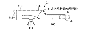
次に、第8の実施の形態を図16を参照して説明する。なお、上記各実施の形態と同様の構成及び作用については、同一符号を付してその説明を省略する。   Next, an eighth embodiment will be described with reference to FIG. In addition, about the structure and effect | action similar to said each embodiment, the same code | symbol is attached | subjected and the description is abbreviate | omitted.

この第8の実施の形態は、上記第7の実施の形態の外側通路部107に代えて、連通口遮蔽部としての方向規制部である仕切り部121を備えるものである。   In the eighth embodiment, a partition 121 that is a direction restricting portion serving as a communication port shielding portion is provided instead of the outer passage portion 107 of the seventh embodiment.

この仕切り部121は、導入口105から内側通路部106に導入された膨張ガスGの一部の連通口113への流れを迂回させるものであり、例えば上記第7の実施の形態の第1基布108の内部の連通口113に間隙を介して対向する位置で、かつ、この連通口113の上方に、エアバッグ本体部31の長手方向に沿って線状に設けられている。また、この仕切り部121は、一端側である後端側、すなわち導入口105側が内側通路部106の下端近傍に位置しているとともに、この後端側から、他端側である前端側、すなわち通気口112側へと、徐々に上方に傾斜するように湾曲して形成されている。すなわち、この仕切り部121は、導入口105と連通口113との間に位置しており、エアバッグ本体部31の長手方向に沿って内側通路部106の一部を導入口105と連通口113との間で仕切っている。換言すれば、内側通路部106は、仕切り部121によって、上下方向に簡易的な二層構造に区画されている。さらに、この仕切り部121は、例えば縫製、接着、あるいは縫製とシール手段との併用などにより構成されている。   This partition part 121 bypasses the flow of the expanded gas G introduced from the inlet port 105 into the inner passage part 106 to a part of the communication port 113, and is, for example, the first base of the seventh embodiment. The cloth 108 is linearly provided along the longitudinal direction of the airbag main body 31 at a position facing the communication port 113 inside the cloth 108 with a gap therebetween and above the communication port 113. Further, the partition portion 121 has a rear end side that is one end side, that is, the introduction port 105 side is located in the vicinity of the lower end of the inner passage portion 106, and from this rear end side, the front end side that is the other end side, that is, It is formed so as to be gradually inclined upward toward the vent 112. That is, the partition 121 is located between the introduction port 105 and the communication port 113, and a part of the inner passage portion 106 is partly connected to the introduction port 105 and the communication port 113 along the longitudinal direction of the airbag main body 31. It partitions between. In other words, the inner passage portion 106 is partitioned into a simple two-layer structure in the vertical direction by the partition portion 121. Further, the partition part 121 is configured by, for example, sewing, bonding, or a combination of sewing and sealing means.

そして、ガス供給部103を形成する際には、まず、予め形成した第1基布108を折り曲げて一側と他側とを重ね、互いに重なり合った上側の縁部に亘ってそれぞれ第2接合部119により接合し、この第1基布108の連通口113の上方の位置を、仕切り部121によって接合することで、ガス供給部103を完成する。   When the gas supply unit 103 is formed, first, the first base fabric 108 formed in advance is folded so that the one side and the other side are overlapped, and the second joint portions are respectively stretched over the overlapping upper edges. The gas supply part 103 is completed by joining by 119 and joining the position above the communication port 113 of this 1st base fabric 108 by the partition part 121. FIG.

このように構成したガス供給部103を備えるエアバッグ10は、インフレータからの膨張ガスGが接続管43を介し導入口105からガス供給部103内の内側通路部106内へと導入されると、この内側通路部106に沿って前方へとガイドされ、一部が通気口112からガス案内部35へと出て、ガス案内部35を長手方向全体、すなわち前端部から後端部に亘って均一、あるいは略均一に迅速に膨張展開させる。また、残りの膨張ガスGは、仕切り部121に衝突してこの仕切り部121を迂回して流れが低減された状態で連通口113から内側通路部106の下方へと出て、膨張部36(前席保護部41及び後席保護部42)を所定面24に沿った下方に迅速にカーテン状に膨張展開させる。   In the airbag 10 including the gas supply unit 103 configured as described above, when the inflation gas G from the inflator is introduced from the introduction port 105 into the inner passage portion 106 in the gas supply unit 103 via the connection pipe 43, Guided forward along this inner passage portion 106, a part exits from the vent 112 to the gas guide portion 35, and the gas guide portion 35 is uniform over the entire longitudinal direction, that is, from the front end portion to the rear end portion. Or, it is inflated and deployed almost uniformly and rapidly. In addition, the remaining expanded gas G collides with the partition 121 and bypasses the partition 121 and flows out from the communication port 113 to the lower side of the inner passage 106 in a state where the flow is reduced. The front seat protection part 41 and the rear seat protection part 42) are rapidly inflated and deployed in a curtain shape downward along the predetermined surface 24.

このように、上記第8の実施の形態によれば、仕切り部121によって、エアバッグ本体部31の長手方向に沿って内側通路部106の一部を導入口105と連通口113との間で仕切り、導入口105から内側通路部106に導入された膨張ガスGの一部の連通口113への流れを迂回させることにより、連通口113を介してエアバッグ本体部31内に供給される膨張ガスGのエアバッグ本体部31の長手方向と交差(直交)する短手方向への流れをより確実に低減できるとともに、他の部材(基布)などを別途用いることなく、エアバッグ本体部31の長手方向と交差(直交)する短手方向への流れを低減させる構成を容易に形成でき、部品点数を最小限に抑制してエアバッグ10の製造コストを低減できる。   Thus, according to the eighth embodiment, a part of the inner passage portion 106 is disposed between the inlet 105 and the communication port 113 along the longitudinal direction of the airbag main body 31 by the partition 121. Inflation supplied into the airbag main body 31 through the communication port 113 by bypassing the flow of a part of the expansion gas G introduced from the introduction port 105 into the inner passage unit 106 to the communication port 113. The flow of the gas G in the short direction intersecting (orthogonal) with the longitudinal direction of the airbag main body 31 can be more reliably reduced, and the airbag main body 31 can be used without using another member (base fabric). Thus, it is possible to easily form a configuration that reduces the flow in the short direction intersecting (orthogonal) with the longitudinal direction of the vehicle, minimizing the number of components, and reducing the manufacturing cost of the airbag 10.

なお、上記第7及び第8の実施の形態において、内側通路部106は、例えば複数枚の基布などによって形成することもできる。   In the seventh and eighth embodiments, the inner passage portion 106 can be formed of, for example, a plurality of base cloths.

また、上記の各実施の形態において、膨張部36の内部は、エアバッグ接合部の内側接合部38によって任意の形状に区画できる。   Further, in each of the above embodiments, the inside of the inflatable portion 36 can be partitioned into an arbitrary shape by the inner joint portion 38 of the airbag joint portion.

また、エアバッグ10は、上側から下側に向かって展開して自動車の側方の窓部18を覆う構成に限られず、例えばドアの上部から上側に向かって展開する、いわゆるドアマウントエアバッグ、あるいは、シートの背部の側部から前側に向かって展開する、いわゆるサイドエアバッグなど、所定面に沿って面状に膨張展開する必要がある適宜のエアバッグ装置に適用できる。   Further, the airbag 10 is not limited to a configuration that is deployed from the upper side to the lower side and covers the side window 18 of the automobile, for example, a so-called door mount airbag that is deployed from the upper part of the door toward the upper side, Alternatively, the present invention can be applied to an appropriate airbag device that needs to be inflated and deployed in a planar shape along a predetermined surface, such as a so-called side airbag that is deployed from the back side of the seat toward the front side.

本発明は、例えば自動車の側部の窓部に沿って取り付けられ展開することで乗員を保護するエアバッグに適用できる。   The present invention can be applied to, for example, an airbag that protects an occupant by being mounted and deployed along a side window of an automobile.

10 エアバッグ
24 所定面
31 エアバッグ本体部
32,103 ガス供給部
36 膨張部
44,105 導入口
46,106 通路部である内側通路部
47,107 方向規制部である外側通路部
58,113 連通口
83 第1外側通路部
84 第2外側通路部
85 方向規制部
101,121 方向規制部である仕切り部
G 膨張ガス
10 airbag
24 Predetermined surface
31 Airbag body
32,103 Gas supply section
36 Expansion part
44,105 introduction port
46,106 Inside passage part which is passage part
47,107 Outer passage part which is direction restriction part
58,113 communication port
83 First outer passage
84 Second outer passage
85 Direction control part
101, 121 Partition that is a direction regulating part G Expansion gas

Claims (4)

膨張ガスの導入により膨張する膨張部を備え、長手状に設けられ、車室の所定面を覆い前記車室の乗員に対向して展開可能な袋状のエアバッグ本体部と、
このエアバッグ本体部とは別個に設けられ、このエアバッグ本体部の内部にこのエアバッグ本体部の展開用の膨張ガスを供給するガス供給部とを具備し、
前記ガス供給部は、
膨張ガスが導入される導入口と、
この導入口から導入された膨張ガスを前記エアバッグ本体部の長手方向に沿って導いてこのエアバッグ本体部内に供給する通路部と、
この通路部に前記エアバッグ本体部の長手方向と交差する方向に向けて設けられた連通口と、
この連通口に少なくとも一部が対向し、この連通口を介して前記エアバッグ本体部内に供給される膨張ガスの一部の流れ方向を規制して膨張ガスの前記エアバッグ本体部の長手方向と交差する方向への流れを低減する方向規制部とを備え
前記方向規制部の下方に前記膨張部が位置している
ことを特徴とするエアバッグ。
An inflatable portion that is inflated by introduction of inflatable gas, is provided in a longitudinal shape, covers a predetermined surface of the passenger compartment, and is deployable facing an occupant in the passenger compartment;
Provided separately from the airbag main body, and includes a gas supply section for supplying an expansion gas for deployment of the airbag main body into the airbag main body,
The gas supply unit
An inlet through which inflation gas is introduced;
And have guide along longitudinally passage for supplying the airbag body portion of the airbag body portion introduced inflation gas from the inlet port,
A communication port provided in a direction intersecting the longitudinal direction of the airbag main body portion in the passage portion;
At least a part of the communication port faces the communication port, and a flow direction of a part of the inflation gas supplied into the airbag main body through the communication port is regulated to control the longitudinal direction of the airbag body part of the inflation gas. With a direction regulating part that reduces the flow in the intersecting direction ,
The airbag according to claim 1, wherein the inflatable part is positioned below the direction restricting part .
方向規制部は、少なくとも一部が連通口に対向して通路部の外部に位置し、前記連通口から前記通路部の外部に出た膨張ガスをエアバッグ本体部の長手方向に導く外側通路部である
ことを特徴とする請求項1記載のエアバッグ。
The direction restricting portion is an outer passage portion that is at least partially opposed to the communication port and located outside the passage portion, and guides the inflation gas that has flowed out of the passage portion from the communication port in the longitudinal direction of the airbag main body portion. The airbag according to claim 1, wherein:
方向規制部は、
少なくとも一部が連通口に対向して通路部の外部に位置し、前記連通口から前記通路部の外部に出た膨張ガスをエアバッグ本体部の長手方向に導く第1外側通路部と、
この第1外側通路部の一部を覆い、この第1外側通路部の外部に出た膨張ガスの少なくとも一部を前記エアバッグ本体部の長手方向に導く第2外側通路部とを備えている
ことを特徴とする請求項1記載のエアバッグ。
Direction control part
A first outer passage portion that is located outside the passage portion at least partially facing the communication port and guides the inflation gas that has flowed out of the passage portion from the communication port in the longitudinal direction of the airbag body portion;
A second outer passage portion that covers a part of the first outer passage portion and guides at least a part of the inflation gas that has come out of the first outer passage portion in the longitudinal direction of the airbag main body portion; The airbag according to claim 1.
方向規制部は、エアバッグ本体部の長手方向に沿って通路部の一部を導入口と連通口との間で仕切り、前記導入口から前記通路部に導入された膨張ガスの一部の前記連通口への流れを迂回させる仕切り部である
ことを特徴とする請求項1記載のエアバッグ。
The direction regulating part partitions a part of the passage part between the introduction port and the communication port along the longitudinal direction of the airbag main body part, and the part of the inflation gas introduced into the passage part from the introduction port The airbag according to claim 1, wherein the airbag is a partition that bypasses the flow to the communication port.
JP2011106344A 2011-05-11 2011-05-11 Airbag Active JP5748552B2 (en)

Priority Applications (1)

Application Number Priority Date Filing Date Title
JP2011106344A JP5748552B2 (en) 2011-05-11 2011-05-11 Airbag

Applications Claiming Priority (1)

Application Number Priority Date Filing Date Title
JP2011106344A JP5748552B2 (en) 2011-05-11 2011-05-11 Airbag

Publications (2)

Publication Number Publication Date
JP2012236491A JP2012236491A (en) 2012-12-06
JP5748552B2 true JP5748552B2 (en) 2015-07-15

Family

ID=47459816

Family Applications (1)

Application Number Title Priority Date Filing Date
JP2011106344A Active JP5748552B2 (en) 2011-05-11 2011-05-11 Airbag

Country Status (1)

Country Link
JP (1) JP5748552B2 (en)

Families Citing this family (3)

* Cited by examiner, † Cited by third party
Publication number Priority date Publication date Assignee Title
JP6111073B2 (en) * 2013-01-10 2017-04-05 セーレン株式会社 Curtain airbag
JP6947127B2 (en) * 2018-06-25 2021-10-13 豊田合成株式会社 Head protection airbag
JP7384776B2 (en) * 2020-10-22 2023-11-21 トヨタ自動車株式会社 Vehicle side airbag

Family Cites Families (5)

* Cited by examiner, † Cited by third party
Publication number Priority date Publication date Assignee Title
US6073961A (en) * 1998-02-20 2000-06-13 Breed Automotive Technology, Inc. Inflatable side airbag curtain module
US6450529B1 (en) * 2000-06-23 2002-09-17 Breed Automotive Technologies, Inc. Inflatable side air bag curtain module with chamber separators
DE10321066B4 (en) * 2003-05-10 2008-07-31 Autoliv Development Ab Airbag arrangement for motor vehicles
JP5117933B2 (en) * 2008-06-06 2013-01-16 芦森工業株式会社 Airbag device
JP5029575B2 (en) * 2008-11-12 2012-09-19 豊田合成株式会社 Head protection airbag

Also Published As

Publication number Publication date
JP2012236491A (en) 2012-12-06

Similar Documents

Publication Publication Date Title
US7163233B2 (en) Head-protecting airbag
JP4947773B2 (en) Air bag, air bag device, and air bag folding method
JP4432932B2 (en) Vehicle knee airbag device and vehicle knee airbag deployment method
JP5366774B2 (en) Air bag and air bag folding method
JP5748552B2 (en) Airbag
JP5478219B2 (en) Airbag
JP5429974B2 (en) Air bag and air bag device
JP6872373B2 (en) Airbag
JP5550382B2 (en) Airbag
JP2010052513A (en) Airbag and airbag device
JP5435913B2 (en) Airbag device
JP2011057028A (en) Airbag
JP2016124497A (en) Air bag
JP4490031B2 (en) Airbag
JP6004577B2 (en) Airbag
JP2010083240A (en) Air-bag and airbag device
JP4089550B2 (en) Head protection airbag device
JP4019919B2 (en) Head protection airbag device airbag
JP5131982B2 (en) Air bag and air bag device
JP2013203171A (en) Airbag
JP4919476B2 (en) Air bag and air bag device
JP5414089B2 (en) Airbag device
JP2008007065A (en) Airbag and airbag device
JP5191045B2 (en) Airbag device
JP5627398B2 (en) Curtain airbag

Legal Events

Date Code Title Description
A621 Written request for application examination

Free format text: JAPANESE INTERMEDIATE CODE: A621

Effective date: 20140509

A977 Report on retrieval

Free format text: JAPANESE INTERMEDIATE CODE: A971007

Effective date: 20150205

A131 Notification of reasons for refusal

Free format text: JAPANESE INTERMEDIATE CODE: A131

Effective date: 20150225

A521 Request for written amendment filed

Free format text: JAPANESE INTERMEDIATE CODE: A523

Effective date: 20150409

TRDD Decision of grant or rejection written
A01 Written decision to grant a patent or to grant a registration (utility model)

Free format text: JAPANESE INTERMEDIATE CODE: A01

Effective date: 20150507

A61 First payment of annual fees (during grant procedure)

Free format text: JAPANESE INTERMEDIATE CODE: A61

Effective date: 20150512

R150 Certificate of patent or registration of utility model

Ref document number: 5748552

Country of ref document: JP

Free format text: JAPANESE INTERMEDIATE CODE: R150

R250 Receipt of annual fees

Free format text: JAPANESE INTERMEDIATE CODE: R250

R250 Receipt of annual fees

Free format text: JAPANESE INTERMEDIATE CODE: R250

R250 Receipt of annual fees

Free format text: JAPANESE INTERMEDIATE CODE: R250

R250 Receipt of annual fees

Free format text: JAPANESE INTERMEDIATE CODE: R250

R250 Receipt of annual fees

Free format text: JAPANESE INTERMEDIATE CODE: R250

R250 Receipt of annual fees

Free format text: JAPANESE INTERMEDIATE CODE: R250

R250 Receipt of annual fees

Free format text: JAPANESE INTERMEDIATE CODE: R250

R250 Receipt of annual fees

Free format text: JAPANESE INTERMEDIATE CODE: R250