JP4919476B2 - Air bag and air bag device - Google Patents

Air bag and air bag device Download PDF

Info

Publication number
JP4919476B2
JP4919476B2 JP2006203419A JP2006203419A JP4919476B2 JP 4919476 B2 JP4919476 B2 JP 4919476B2 JP 2006203419 A JP2006203419 A JP 2006203419A JP 2006203419 A JP2006203419 A JP 2006203419A JP 4919476 B2 JP4919476 B2 JP 4919476B2
Authority
JP
Japan
Prior art keywords
airbag
gas
folded
predetermined surface
pillar
Prior art date
Legal status (The legal status is an assumption and is not a legal conclusion. Google has not performed a legal analysis and makes no representation as to the accuracy of the status listed.)
Expired - Fee Related
Application number
JP2006203419A
Other languages
Japanese (ja)
Other versions
JP2008030527A (en
Inventor
智理 石川
陽平 木内
寛行 岩本
高志 植田
光宏 吉田
秀明 斉藤
Current Assignee (The listed assignees may be inaccurate. Google has not performed a legal analysis and makes no representation or warranty as to the accuracy of the list.)
Nihon Plast Co Ltd
Original Assignee
Nihon Plast Co Ltd
Priority date (The priority date is an assumption and is not a legal conclusion. Google has not performed a legal analysis and makes no representation as to the accuracy of the date listed.)
Filing date
Publication date
Application filed by Nihon Plast Co Ltd filed Critical Nihon Plast Co Ltd
Priority to JP2006203419A priority Critical patent/JP4919476B2/en
Publication of JP2008030527A publication Critical patent/JP2008030527A/en
Application granted granted Critical
Publication of JP4919476B2 publication Critical patent/JP4919476B2/en
Expired - Fee Related legal-status Critical Current
Anticipated expiration legal-status Critical

Links

Images

Description

本発明は、例えば、自動車の車室の側部の窓部に沿って展開するエアバッグ及びエアバッグ装置に関する。   The present invention relates to an airbag and an airbag device that are deployed along, for example, a window portion on a side portion of a vehicle cabin.

従来、ガスを導入して膨張展開するエアバッグを備えたエアバッグ装置について、自動車の車室の側方のドアの窓部などに沿って面状に展開するいわゆるカーテンエアバッグ装置が知られている。このようなエアバッグ装置は、通常時は、前後方向を長手方向として細長く折り畳まれ、車室側面の窓部の上縁部に沿って配置されている。そして、側面衝突や横転(ロールオーバー)などの衝撃を受けた際に、インフレータから袋状をなす膨張部にガスが供給されてエアバッグが展開し、窓部などに沿って下方に膨張展開するようになっている。   2. Description of the Related Art Conventionally, an airbag apparatus having an airbag that inflates and deploys by introducing gas is known as a so-called curtain airbag apparatus that deploys in a planar shape along a window portion of a door on the side of a vehicle cabin. Yes. Such an airbag device is normally folded in an elongated manner with the front-rear direction as the longitudinal direction, and is disposed along the upper edge of the window portion on the side surface of the passenger compartment. When an impact such as a side collision or rollover (rollover) is received, gas is supplied from the inflator to the inflatable portion forming the bag shape, and the airbag is deployed, and inflated and deployed downward along the window and the like. It is like that.

このようなエアバッグの折り畳み方法について、エアバッグを下端部からロール状に集積して集積部を形成するとともに、ガスが導入される膨張部の上側の部分を両側に扁平に広げて腕部とし、これら腕部をロール状に集積した集積部の両側を囲むように折り畳んだ構成が知られている(例えば、特許文献1参照。)。この構成では、エアバッグにガスを導入すると、まず腕部が迅速に展開して、集積部を案内しつつ下方に押し出し、この後、集積部が窓部に沿って展開し、好ましい展開特性の実現が可能となっている。   About such an airbag folding method, the airbag is accumulated in a roll shape from the lower end portion to form an accumulation portion, and the upper portion of the inflated portion into which gas is introduced is flattened on both sides to form an arm portion. In addition, a configuration is known in which these arm portions are folded so as to surround both sides of a stacking unit in which rolls are stacked (see, for example, Patent Document 1). In this configuration, when the gas is introduced into the airbag, the arm portion is first rapidly deployed and pushed downward while guiding the accumulation portion, and thereafter, the accumulation portion is deployed along the window portion, and the preferred deployment characteristics are obtained. Realization is possible.

また、このようなカーテンエアバッグ装置のエアバッグについて、横転時の乗員の車外放出を防止し、また、エアバッグを車体に強固に取り付ける多数の取り付け点を確保するなどのために、車室の側部を広く覆う基布を備えたエアバッグが知られている。さらに、このようなエアバッグについて、ガスの圧力を有効に利用するために、エアバッグの一部に1枚の基布などにて構成されガスが導入されない非展開部を設ける構成が知られている(例えば、特許文献2参照。)。ここで、ガスが導入されない非展開部が、エアバッグの上部の前端部の一部などに設けられている構成では、非展開部の部分を扁平に広げるように折り畳むことができず、特許文献1の構成の適用は困難であり、この非展開部の部分を集積部と連続してロール状に折り畳むと、円滑迅速に展開する所望の展開特性の実現が容易でない問題を有している。
特開2003−160019号公報 (第1頁、図1) 特開2004−175225号公報 (図1、図3)
In addition, with respect to the airbag of such a curtain airbag device, in order to prevent the passenger from being released from the vehicle during a rollover, and to secure a large number of attachment points for firmly attaching the airbag to the vehicle body, There is known an airbag including a base cloth that covers a wide side. Furthermore, in order to effectively use the pressure of gas, a configuration in which a non-deployment portion that is configured by a single base cloth or the like and is not introduced with gas is provided in such an airbag is known. (For example, see Patent Document 2). Here, in the configuration in which the non-deployment portion where the gas is not introduced is provided in a part of the front end portion of the upper portion of the airbag, the portion of the non-deployment portion cannot be folded so as to be flattened. Application of the structure of 1 is difficult, and when this non-development part is folded into a roll shape continuously with the stacking part, there is a problem that it is not easy to realize a desired development characteristic for smooth and rapid development.
JP 2003-160019 A (first page, FIG. 1) JP 2004-175225 A (FIGS. 1 and 3)

上記のように、カーテンエアバッグ装置のエアバッグについて、ガスが導入されない非展開部が、エアバッグの上部の一部に設けられている構成では、非展開部の部分を扁平に広げるように折り畳むことはできず、この非展開部の部分を集積部と連続してロール状に折り畳むと、円滑迅速に展開する所望の展開特性の実現が容易でない問題を有している。   As described above, in the configuration of the airbag of the curtain airbag device, in the configuration in which the non-deployment portion where the gas is not introduced is provided in a part of the upper portion of the airbag, the non-deployment portion is folded so as to be flattened. However, if this non-development portion is folded into a roll continuously with the stacking portion, there is a problem that it is not easy to realize a desired development characteristic for smooth and rapid development.

本発明は、このような点に鑑みなされたもので、円滑迅速に膨張展開可能に折り畳まれたエアバッグ及びエアバッグ装置を提供することを目的とする。   The present invention has been made in view of these points, and an object thereof is to provide an airbag and an airbag apparatus that are folded so as to be inflated and deployed smoothly and rapidly.

請求項1記載のエアバッグは、所定面に沿って、この所定面を覆って膨張展開するエアバッグであって、ガスが導入されるガス導入部と、このガス導入部に連通する膨張部と、この膨張部に連通せずガスが導入されない非膨張部とを具備し、前記ガス導入部に連通する前記膨張部を含み、両側方に向かい扁平に折り畳まれた案内折畳部と、この案内折畳部に位置する前記膨張部に連通する前記膨張部を含んで折り畳まれ、前記案内折畳部に両側部が囲まれた集積部と、前記集積部と前記所定面との間に配置され、前記案内折畳部前記集積部に隣接する前記非膨張部を含んで蛇腹状に折り畳まれて前記集積部を展開させる非膨張折畳部とを備えたものである。 The airbag according to claim 1 is an airbag that is inflated and deployed along a predetermined surface so as to cover the predetermined surface, and a gas introducing portion into which gas is introduced, and an inflating portion communicating with the gas introducing portion. A non-inflatable portion that does not communicate with the inflatable portion and does not introduce gas, includes the inflatable portion that communicates with the gas introducing portion, and is folded into a flat shape toward both sides, and this guide Folded including the inflatable part communicating with the inflatable part located in the foldable part, the accumulating part surrounded on both sides by the guide foldable part, and disposed between the accumulating part and the predetermined surface And a non-inflatable folding part that includes the non-inflatable part adjacent to the guide folding part and the stacking part and is folded in a bellows shape to expand the stacking part .

そして、この構成では、エアバッグのガス導入部にガスが導入されると、このガス導入部に連通する膨張部を折り畳んだ案内折畳部が展開し、折り畳んだ集積部を所定の方向に押し出すように案内する。次いで、集積部が所定面に沿って、この所定面を覆って膨張展開する。案内折畳部集積部に隣接する非膨張部は蛇腹状に折り畳んだ非膨張折畳部として集積部と所定面との間に配置したため、案内折畳部の展開に伴い集積部の所定面から離間する方向の円滑迅速な移動を許容し、エアバッグが円滑迅速に膨張展開する。 In this configuration, when the gas is introduced into the gas introduction portion of the airbag, the guide fold portion in which the expansion portion communicating with the gas introduction portion is folded is deployed, and the folded accumulation portion is pushed out in a predetermined direction. To guide you. Next, the accumulating portion expands and develops along the predetermined surface so as to cover the predetermined surface. Since the non-inflatable portion adjacent to the guide folds the integrated unit is disposed between the as a non-inflatable folding portion folded in a bellows-like stacking unit and a predetermined surface, the integrated unit with the deployment of the guide folds The airbag is allowed to move smoothly and quickly in the direction away from the predetermined surface , and the airbag is inflated and deployed smoothly and rapidly.

求項記載のエアバッグ装置は、請求項記載のエアバッグと、このエアバッグのガス導入部にガスを供給するインフレ−タとを具備し、所定面は、車両の車室の窓部に沿った面部であり、前記エアバッグは、前記所定面の上縁に沿って折り畳んで収納されたものである。 Airbag apparatus Motomeko 2 described, the air bag according to claim 1, the supply gas to the gas introduction section of the air bag inflation -; and a motor, the predetermined surface is a window of the vehicle compartment of the vehicle The airbag is stored by being folded along the upper edge of the predetermined surface.

そして、この構成では、請求項記載のエアバッグを備えたため、車両の衝突時などにインフレータからガスを供給することにより、車室の窓部に沿ってエアバッグが上側から下側に円滑迅速に展開し、車室の窓部がエアバッグにより円滑迅速に覆われる。 In this configuration, since the airbag according to claim 1 is provided, gas is supplied from the inflator at the time of a vehicle collision or the like, so that the airbag is smoothly and quickly moved from the upper side to the lower side along the window portion of the passenger compartment. The window of the passenger compartment is smoothly and quickly covered with the airbag.

本発明によれば、案内折畳部集積部に隣接する非膨張部は蛇腹状に折り畳んだ非膨張折畳部として集積部と所定面との間に配置したため、案内折畳部の展開に伴い集積部の所定面から離間する方向の円滑迅速な移動を許容し、エアバッグを円滑迅速に膨張展開させることができる。 According to the present invention, since the non-inflatable portion adjacent to the guide folds the integrated unit is disposed between the as a non-inflatable folding portion folded in a bellows-like stacking unit and a predetermined surface, guiding folding unit Accordingly, the airbag can be smoothly and quickly inflated and deployed by allowing the airbag to move smoothly and quickly in a direction away from the predetermined surface of the stacking portion.

以下、本発明のエアバッグ及びエアバッグ装置の一実施の形態を図面を参照して説明する。   Hereinafter, an embodiment of an airbag and an airbag device of the present invention will be described with reference to the drawings.

図1ないし図4において、1はエアバッグで、このエアバッグ1を備えたエアバッグ装置2は、カーテンエアバッグ装置とも呼ばれるもので、車両である自動車の車体3の車室の収納位置としてのドア開口部の上縁のルーフサイド部5に配置されている。そして、このエアバッグ1は、カーテンエアバッグ、側突用エアバッグ、インフレータブルカーテン、あるいは頭部保護用エアバッグなどとも呼ばれるもので、側面衝突の衝撃を受けた際や横転(ロールオーバー)の際などに、乗員の側方にほぼ面状に展開し、被保護物である乗員を保護するようになっている。なお、以下、前後、上下、両側などの方向は、車両の直進方向を基準とし、図1において、矢印Aで示す方向が車内側、矢印Bで示す方向が車外側、矢印Cで示す方向が上側Cであり、図2ないし図4において、矢印Fで示す方向が前方である。   In FIG. 1 to FIG. 4, reference numeral 1 denotes an airbag, and an airbag device 2 provided with the airbag 1 is also called a curtain airbag device, and serves as a storage position of a compartment of a vehicle body 3 of an automobile, which is a vehicle. It arrange | positions at the roof side part 5 of the upper edge of a door opening part. The airbag 1 is also called a curtain airbag, a side-impact airbag, an inflatable curtain, or a head protection airbag. The airbag 1 is subjected to a side impact or rollover. For example, it is developed in a plane substantially on the side of the occupant to protect the occupant as a protected object. In the following, directions such as front and rear, up and down, and both sides are based on the straight traveling direction of the vehicle. In FIG. 1, the direction indicated by arrow A is the inside of the vehicle, the direction indicated by arrow B is the outside of the vehicle, and the direction indicated by arrow C is It is the upper side C, and the direction shown by the arrow F in FIGS.

そして、この自動車の車体3は、図示しないが、車室内に乗員が着座可能な前席及び後席を備え、これら前席及び後席に対応して、それぞれ上部に開口可能な開口部としての所定面を構成する窓部(サイドウィンドウ)8を備えた図示しないドアが設けられている。また、車室の両側には、前側から順に、Aピラーとも呼ばれるフロントピラー、柱状部であるピラー部としてのBピラーとも呼ばれるセンターピラー、Cピラーとも呼ばれるリアピラーが設けられている。また、これらピラーの上側、すなわち窓部8の一縁部である上縁部に、ルーフサイドレールなどとも呼ばれる被取付部材を構成する車体パネル10が設けられ、この車体パネル10を介して天井部としての天井パネルが支持されている。そして、これら窓部8、ドア及び各ピラー、及び車体パネル10の一部により、車室の両側部に所定面14が構成されている。また、両側のフロントピラーの前側にはフロントガラス(フロントウインドシールド)が設けられ、両側のリアピラーの後側にはリアガラスが設けられている。そして、収納位置としてのルーフサイド部5は、天井パネルの両側の縁部の部分から、この縁部の部分といわば交差する方向に伸びるフロントピラーのほぼ全長にかかる部分にまで設定され、これら天井パネルの縁部の部分とフロントピラーとで仮想的に構成される内角の側にエアバッグ1が展開する所定面14が設定される。   The vehicle body 3 includes a front seat and a rear seat that can be seated by an occupant in the passenger compartment, and is provided as an opening that can be opened at the top corresponding to the front seat and the rear seat. A door (not shown) provided with a window portion (side window) 8 constituting a predetermined surface is provided. Further, on both sides of the passenger compartment, a front pillar called A pillar, a center pillar called B pillar as a pillar part which is a columnar part, and a rear pillar called C pillar are provided in order from the front side. In addition, a vehicle body panel 10 that constitutes a member to be attached, which is also called a roof side rail, is provided on the upper side of these pillars, that is, the upper edge portion that is one edge portion of the window portion 8. As a ceiling panel is supported. The window 8, the door and each pillar, and a part of the vehicle body panel 10 constitute a predetermined surface 14 on both sides of the passenger compartment. A front glass (front windshield) is provided on the front side of the front pillars on both sides, and a rear glass is provided on the rear side of the rear pillars on both sides. And the roof side part 5 as a storage position is set from the edge part of the both sides of a ceiling panel to the part concerning the substantially full length of the front pillar extended in the direction which intersects with this edge part. A predetermined surface 14 on which the airbag 1 is deployed is set on the inner corner side virtually formed by the edge portion of the panel and the front pillar.

また、車体パネル及び天井パネルの車室側は、各ピラーの一部とともに、軟質すなわち変形可能な天井板であり室内装飾パネルであるルーフライニング(ヘッドライニング)15により覆われている。また、各座席には、シートベルトが設けられ、センターピラーには、これらシートベルトを支持する支持部が設けられている。また、各ピラーの全長あるいは一部の車室側には、それぞれ内装材である第1ないし第3のピラーガーニッシュが取り付けられ、各ピラーが覆われている。さらに、図示しないが、車体パネルの下端部には、軟質の樹脂などにて形成された弾性変形可能なパッキング体が取り付けられている。このパッキング体は、ウェルトあるいはボディシールなどとも呼ばれるもので、各ドアの上部が当接して密着するようになっている。   The vehicle body side of the vehicle body panel and the ceiling panel are covered with roof lining (headlining) 15 which is a soft or deformable ceiling plate and an interior decoration panel together with a part of each pillar. Each seat is provided with a seat belt, and the center pillar is provided with a support portion for supporting these seat belts. In addition, first to third pillar garnishes, which are interior materials, are attached to the entire length of each pillar or a part of the passenger compartment, respectively, to cover each pillar. Further, although not shown, an elastically deformable packing body made of a soft resin or the like is attached to the lower end portion of the vehicle body panel. This packing body is also called a welt or a body seal, and the upper portions of the doors come into contact with each other and come into close contact with each other.

そして、エアバッグ装置2は、前後の座席の乗員を保護可能な、いわゆる前後席用エアバッグであり、車体パネルとルーフライニングとなどに囲まれたルーフサイド部5に細長く折り畳んで収納されたエアバッグ1と、後席の後方あるいは上方に収納されこのエアバッグ1にガスを供給するガス発生器であるインフレータ25となどを備えている。また、このエアバッグ装置2は、必要に応じて、エアバッグ1を車体パネルに取り付ける金属板をプレス加工などして形成された取付ブラケット、折り畳んだエアバッグ1に沿って取り付けられて展開時にエアバッグ1を保護する断面略L字状をなす樹脂製のプロテクタ27、及び折り畳んだエアバッグ1の形状を保持する破断可能な筒状あるいはひも状の形状保持部材としてのスリーブ28、エアバッグ1の前端部に連結されたテザーベルト29などが備えられている。   The airbag device 2 is a so-called front and rear seat airbag capable of protecting passengers in the front and rear seats. The airbag device 2 is folded and stored in the roof side portion 5 surrounded by the vehicle body panel and roof lining. A bag 1 and an inflator 25 that is housed behind or above the rear seat and supplies gas to the airbag 1 are provided. In addition, the airbag device 2 is attached along a mounting bracket formed by pressing a metal plate that attaches the airbag 1 to the vehicle body panel, or the folded airbag 1 as necessary. A protector 27 made of resin having a substantially L-shaped cross section for protecting the bag 1, a sleeve 28 as a breakable cylindrical or string-like shape holding member that holds the shape of the folded airbag 1, and the airbag 1 A tether belt 29 or the like connected to the front end portion is provided.

そして、エアバッグ1は、単数あるいは複数の基布を組み合わせ、例えば1枚の基布を折り返し、あるいは2枚の基布を重ねて接合して、扁平な袋状に形成されたエアバッグ本体部31と、このエアバッグ本体部31の複数カ所から延設された取付部を構成する取付片部32となどを備え、細長く折り畳んでルーフサイド部5に収納される。   The airbag 1 is a combination of a single base fabric or a plurality of base fabrics. For example, an airbag main body formed in a flat bag shape by folding back one base fabric or stacking and joining two base fabrics. 31 and an attachment piece portion 32 constituting an attachment portion extending from a plurality of locations of the airbag main body portion 31 and the like, and is folded into an elongated shape and stored in the roof side portion 5.

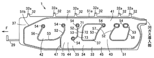
そして、エアバッグ本体部31は、側面視で前後方向を長手方向とする略矩形状で、車室側に配置される内側の基布部33と車体側である外側に配置される外側の基布部34とを重ね、接合部である所定の縫製部で縫い合わせ、図2に示すように、ガスが流入して膨張展開する袋状の膨張部35と、エアバッグ本体部31の後端上部に位置して膨張部35を外部に連通するガス導入部36と、ガスが流入せず膨張展開しない非膨張部37となどが設けられている。   The airbag main body 31 has a substantially rectangular shape with the front-rear direction as the longitudinal direction when viewed from the side, and has an inner base fabric portion 33 disposed on the vehicle compartment side and an outer base disposed on the outer side on the vehicle body side. The cloth portion 34 is overlapped and stitched at a predetermined sewing portion as a joint portion, and as shown in FIG. 2, a bag-like inflatable portion 35 that inflates and expands when gas flows in, and an upper rear end portion of the airbag main body 31 There are provided a gas introduction part 36 that communicates with the expansion part 35 to the outside, a non-expansion part 37 that does not allow gas to flow in and does not expand and develop, and the like.

さらに、膨張部35は、中空部である気室であり、エアバッグ本体部31の上縁部に沿って位置するガス案内部41と、このガス案内部41の下流側である下側に連通する開口部用展開部としての第1の膨張部である前席保護部42及び第2の膨張部としての後席保護部43と、これら前席保護部42及び後席保護部43の間に位置する柱状部用展開部としてのピラー被覆部44と、これら保護部42,43及びピラー被覆部44の下流側である下側に連通しエアバッグ本体部31の下縁部に沿って位置する下流側展開部としての下部膨張部45とを備えている。そして、ガス案内部41は、エアバッグ本体部31の上縁部の略全長に沿って、すなわち前後方向を長手方向である軸方向として略水平な柱状に展開する。また、下部膨張部45は、エアバッグ本体部31の下縁部の略全長に沿って、すなわち前後方向を長手方向である軸方向として略水平な柱状に展開するが、所定の位置に設けたガス規制部47により前後に区画されている。さらに、ピラー被覆部44は、センターピラーとほぼ等しい幅寸法か、あるいはセンターピラーよりも大きい幅寸法を有している。   Further, the inflating portion 35 is a hollow air chamber, and communicates with the gas guide portion 41 located along the upper edge portion of the airbag body portion 31 and the lower side, which is the downstream side of the gas guide portion 41. A front seat protection part 42 as a first inflating part as an opening development part and a rear seat protection part 43 as a second inflating part, and between the front seat protection part 42 and the rear seat protection part 43 The pillar covering portion 44 as a deployed portion for the columnar portion is positioned along the lower edge portion of the airbag main body 31 so as to communicate with the lower side, which is the downstream side of the protective portions 42 and 43 and the pillar covering portion 44. And a lower expansion part 45 as a downstream development part. Then, the gas guide portion 41 is developed along a substantially entire length of the upper edge portion of the airbag body portion 31, that is, in a substantially horizontal columnar shape with the front-rear direction as the axial direction which is the longitudinal direction. Further, the lower inflating portion 45 is deployed along a substantially entire length of the lower edge portion of the airbag body portion 31, that is, in a substantially horizontal columnar shape with the front-rear direction as the axial direction which is the longitudinal direction, but provided at a predetermined position. It is divided forward and backward by the gas regulating part 47. Further, the pillar covering portion 44 has a width dimension substantially equal to the center pillar or a width dimension larger than the center pillar.

また、縫製部は、縫製、接着、あるいは縫製とシール手段との併用などにより略気密あるいは高度な気密に構成され、膨張部35の外周を縫製する外周連結部であり確認対象部となる外周縫製部51と、この外周縫製部51に囲まれた領域に位置し保護部42,43及びピラー被覆部44などを区画形成するとともに各部の展開時の幅寸法を規制する規制部52とを備えている。   In addition, the sewing portion is configured to be substantially airtight or highly airtight by sewing, bonding, or a combination of sewing and sealing means, and is an outer periphery connecting portion that sews the outer periphery of the inflating portion 35, and is an outer periphery sewing that is a confirmation target portion. A portion 51 and a restriction portion 52 that is located in an area surrounded by the outer peripheral sewing portion 51 and that defines the protection portions 42 and 43, the pillar covering portion 44, and the like, and restricts the width of each portion when deployed. Yes.

そして、外周縫製部51は、エアバッグ本体部31の外周部の近傍に略沿って形成され、上端縁については、長手方向の中央部から後側部にかけて、エアバッグ本体部31の上端部に近接した直線状の直線部51aが形成されているが、上端縁の長手方向の前側部については、直線部51aの前端部に連続して、前方に向かって下方に向かう傾斜線部51bが形成されている。そこで、この傾斜線部51bの前側上方の部分、すなわち、膨張部35のガス案内部41の下流側である前側に隣接する部分、すなわち、膨張部35の前席保護部42の上側に隣接する部分については、基布は存在するがガスは流入しない非膨張部37が形成されている。なお、この非膨張部37は、内側あるいは外側のいずれか1枚の基布部33,34で構成しても良く、また、2枚の基布部33,34を重ねて形成することもできる。   The outer peripheral sewing portion 51 is formed substantially along the vicinity of the outer peripheral portion of the airbag main body 31, and the upper end edge extends from the central portion in the longitudinal direction to the rear side portion at the upper end of the airbag main body 31. An adjacent straight linear portion 51a is formed, but the front side portion in the longitudinal direction of the upper end edge is formed with an inclined line portion 51b that is continuous with the front end portion of the linear portion 51a and that is directed downward toward the front. Has been. Therefore, a portion above the front side of the inclined line portion 51b, that is, a portion adjacent to the front side downstream of the gas guide portion 41 of the expansion portion 35, that is, adjacent to the upper side of the front seat protection portion 42 of the expansion portion 35. As for the portion, a non-expandable portion 37 where a base fabric is present but gas does not flow is formed. The non-expandable portion 37 may be formed by either one of the inner or outer base fabric portions 33, 34, or may be formed by overlapping the two base fabric portions 33, 34. .

また、この実施の形態では、外周縫製部51を含む縫製部は、糸、ここでは上糸と下糸を用いて構成されているが、この糸は、エアバッグ1を構成する基布とは異なる色で形成されている。例えば、基布は、白色あるいは淡赤色であるのに対し、上糸及び下糸の少なくとも一方の糸は、青色るあいは緑色となっている。   Further, in this embodiment, the sewing portion including the outer periphery sewing portion 51 is constituted by using a thread, here, an upper thread and a lower thread. It is formed with different colors. For example, the base fabric is white or light red, while at least one of the upper thread and the lower thread is green while being blue.

また、規制部52は、膨張部35の1カ所あるいは複数カ所に位置し、外周縫製部51と一体あるいは別体に形成されている。また、各規制部52は、線状をなす線部53と、この線部53の端末あるいはガスの上流側に位置して線部を保護する円環状の保護部54が形成されている。そして、本実施の形態では、規制部52は、前席保護部42に位置する前側規制部56と、後席保護部43に位置する第1及び第2の後側規制部57,58と、ピラー被覆部44に略沿って形成された連結線部71とが形成されている。そして、前側規制部56と第2の後側規制部58は、上側すなわち上流側を開口した略U字状をなし、第1の後側規制部57は、環状に形成されて内部が非膨張部37となっている。また、連結線部71は、本実施の形態では、ピラー被覆部44の後側部を区画形成するもので、エアバッグ1が展開した状態で、ピラー被覆部44すなわちセンターピラーに略沿って垂直状すなわち上下方向を長手方向として形成され、センターピラーの後縁部に沿った直線状の直線部72と、この直線部の下端部に連続し下流側に滑らかに湾曲してセンターピラーの一部に重なる位置まで延設された曲線状の交差部73とを備え、いわば略J字状あるいは略し字状に形成されている。そして、この連結線部71の下端部は、各規制部56,57,58の下端部とほぼあるいは正確に位置合わせされており、ガス規制部47の部分を除いて、ガスの流れを遮ることのない空間が形成されるとともに、これら規制部56,57,58の下側に形成される下部膨張部45は、一部すなわちピラー被覆部44に連続する部分がセンターピラーの下端部を覆うようになっている。   Further, the restricting portion 52 is located at one place or a plurality of places of the inflating portion 35 and is formed integrally with or separately from the outer peripheral sewing portion 51. Each restricting portion 52 is formed with a linear line portion 53 and an annular protection portion 54 that is located at the end of the line portion 53 or upstream of the gas and protects the line portion. In the present embodiment, the restricting portion 52 includes a front restricting portion 56 located in the front seat protecting portion 42, a first and second rear restricting portions 57 and 58 located in the rear seat protecting portion 43, A connecting line portion 71 formed substantially along the pillar covering portion 44 is formed. The front side restricting part 56 and the second rear side restricting part 58 are substantially U-shaped with the upper side, that is, the upstream side opened, and the first rear side restricting part 57 is formed in an annular shape and the inside thereof is not inflated. It is part 37. Further, in the present embodiment, the connecting line portion 71 defines a rear side portion of the pillar covering portion 44, and is perpendicular to the pillar covering portion 44, that is, the center pillar in a state where the airbag 1 is deployed. A straight linear portion 72 formed along the rear edge of the center pillar, and a portion of the center pillar that is smoothly curved downstream and continuous to the lower end of the straight portion. And a curved crossing portion 73 extending to a position overlapping with each other, so that it is formed in a substantially J-shape or abbreviated-shape. And the lower end part of this connection line part 71 is aligned with the lower end part of each regulation part 56,57,58 substantially or correctly, and blocks the gas flow except for the part of the gas regulation part 47. The lower inflatable portion 45 formed below these restricting portions 56, 57, and 58 is formed so that a part thereof, that is, a portion continuing to the pillar covering portion 44 covers the lower end portion of the center pillar. It has become.

さらに、この実施の形態では、規制部52と一体に連続して、ガス規制部47が形成されている。このガス規制部47は、前側規制部56の後端部近傍から下方に垂直状に延設され、外周縫製部51に連続している。そこで、このガス規制部47は、ピラー被覆部44が下部膨張部45に連通する連通部分75の下流側で、下部膨張部45を気密に閉塞している。なお、このガス規制部47の位置は、ピラー被覆部44に近接する位置に限られず、前側規制部56と外周縫製部51とを連結する任意の位置に設けることができる。なお、ガス規制部47は省略することもできる。   Further, in this embodiment, the gas regulating part 47 is formed continuously with the regulating part 52 integrally. The gas restricting portion 47 extends vertically downward from the vicinity of the rear end portion of the front restricting portion 56 and continues to the outer peripheral sewing portion 51. Therefore, the gas regulating part 47 hermetically closes the lower inflating part 45 on the downstream side of the communicating part 75 where the pillar covering part 44 communicates with the lower inflating part 45. The position of the gas restricting portion 47 is not limited to the position close to the pillar covering portion 44, and can be provided at any position where the front restricting portion 56 and the outer peripheral sewing portion 51 are connected. The gas regulating unit 47 can be omitted.

また、内側の基布部33と外側の基布部34との間には、必要に応じて、ガスを案内し、あるいは、展開時の膨張部35の幅寸法を規制する手段として、インナパイプ、前側隔壁体、あるいは後側隔壁体などが縫合などして取り付けられている。   In addition, an inner pipe is provided between the inner base fabric portion 33 and the outer base fabric portion 34 as a means for guiding gas or regulating the width dimension of the expansion portion 35 during deployment as necessary. The front partition body or the rear partition body is attached by sewing or the like.

また、エアバッグ1の取付片部32は、エアバッグ本体部31の上縁部の所定位置に複数形成されている。そして、各取付片部32は、エアバッグ本体部31を構成する基布部33,34と一体に形成され、例えば、内側の基布部33と外側の基布部34とを重ね縫着して形成されている。そして、各取付片部32は、エアバッグ本体部31から舌片状に突設され、円孔状をなす取付孔32aが形成されている。   A plurality of attachment pieces 32 of the airbag 1 are formed at predetermined positions on the upper edge of the airbag body 31. Each attachment piece 32 is formed integrally with the base fabric portions 33 and 34 constituting the airbag main body portion 31. For example, the inner base fabric portion 33 and the outer base fabric portion 34 are overlapped and sewn. Is formed. Each attachment piece 32 protrudes from the airbag body 31 in a tongue-like shape, and an attachment hole 32a having a circular hole shape is formed.

さらに、スリーブ28は、カバーあるいはサックなどとも呼ばれるもので、エアバッグ1を構成する基布と同様の、あるいはエアバッグ1を構成する基布よりも厚さ寸法が小さく若干の透光性を有する基布を円筒状とし、長手方向に沿って縫着して形成されている。また、このスリーブ28には、長手方向に沿って、エアバッグ1が展開する力が加わった時点で破断するテアライン28aが形成されている。そして、スリーブ28には、各取付片部32の位置に対応して、各取付片部32が挿通可能な切り込みであるスリット28bが形成されている。   Further, the sleeve 28 is also called a cover or a sack, and is similar to the base fabric constituting the airbag 1 or has a slightly lighter transmissivity than the base fabric constituting the airbag 1. The base fabric is cylindrical and is formed by sewing along the longitudinal direction. Further, the sleeve 28 is formed with a tear line 28a that breaks along the longitudinal direction when a force to deploy the airbag 1 is applied. The sleeve 28 is formed with slits 28b corresponding to the positions of the attachment piece portions 32, which are cuts through which the attachment piece portions 32 can be inserted.

さらに、図4及び図5に示すように、このスリーブ28には、印刷などにより、複数、本実施の形態では前後一対の位置確認部60が設けられている。各位置確認部60は、スリット28bに対して正確な位置に設けられ、それぞれ所定の間隔を介して上下に離間した一対のマーキング部60aを備えている。   Further, as shown in FIGS. 4 and 5, the sleeve 28 is provided with a plurality of position confirmation portions 60 in the present embodiment by printing or the like, in the present embodiment. Each position confirmation unit 60 includes a pair of marking units 60a which are provided at accurate positions with respect to the slits 28b and are spaced apart from each other at a predetermined interval.

次に、このエアバッグ1の折り畳み工程、エアバッグ装置2の組み立て工程、及び車体3への取付工程を説明する。   Next, a folding process of the airbag 1, an assembly process of the airbag device 2, and an attachment process to the vehicle body 3 will be described.

まず、エアバッグ1は、自動機により、あるいは、手動により折り畳まれ、まず、平面状に広げた状態から、エアバッグ本体部31の先端部すなわち下端部から膨張部35の部分を所定方向すなわち先端部から反所定面14側に巻回してロール状に折り畳み、集積部61を形成する。そして、図1(b)に示すように、この集積部61の上側に位置する膨張部35の部分、すなわち、主としてガス案内部41の部分は、ガス導入部36に直接的すなわち直線的に連通する通気位置62を中心として、両側方に扁平に広げ、両側に腕部64aを有する断面略十字状の案内折畳部64を形成する。そして、この案内折畳部64の両側の腕部64aで、集積部61の上側から両側の部分を被せるようにして囲み、いわばパラソル状に折り畳む。また、図1(a)に示すように、集積部61の上側に位置する非膨張部37の部分は、蛇腹状、例えば断面略W字状に折り畳んで、非膨張折畳部66を形成し、集積部61の一側に沿わせる。   First, the airbag 1 is folded by an automatic machine or manually, and first, from a state where the airbag 1 is spread in a flat shape, the portion of the inflating portion 35 is moved in a predetermined direction, that is, from the distal end portion, that is, the lower end portion of the airbag main body portion 31 to the distal end. The stacking portion 61 is formed by winding the portion from the portion toward the anti-predetermined surface 14 and folding it into a roll shape. As shown in FIG. 1 (b), the portion of the expansion portion 35 located above the accumulation portion 61, that is, the portion of the gas guide portion 41 mainly communicates directly or linearly with the gas introduction portion 36. A guide fold part 64 having a substantially cross-shaped cross section is formed, which is flattened on both sides around the ventilation position 62 and has arm parts 64a on both sides. Then, the arm portions 64a on both sides of the guide fold portion 64 are enclosed so as to cover both sides from the upper side of the stacking portion 61, and are folded in a parasol shape. Further, as shown in FIG. 1 (a), the portion of the non-inflatable portion 37 located above the stacking portion 61 is folded into a bellows shape, for example, a substantially W-shaped cross section, thereby forming a non-inflatable folded portion 66. , Along one side of the stacking unit 61.

そして、このようにエアバッグ本体部31を所定の形状に細長く折り畳んだエアバッグ1にスリーブ28を被せ、エアバッグ1の取付片部32をスリーブ28のスリット28bから引き出すことにより、図3及び図4に示すように、折り畳み形状が保持された状態となる。   Then, the airbag 1 is obtained by covering the airbag main body 31 in a predetermined shape with the sleeve 28, and pulling the attachment piece 32 of the airbag 1 out of the slit 28b of the sleeve 28, as shown in FIGS. As shown in FIG. 4, the folded shape is maintained.

ここで、スリーブ28は、若干の透光性を有するため、収納したエアバッグ1が若干透けて確認でき、特に、基布とは色が異なる外周縫製部51の位置は明確に確認できる。そこで、図4及び図5(a)に示すように、この外周縫製部51の直線部51aが、各位置確認部60において、上下のマーキング部60aの間に位置することを目視あるいは自動機により確認すれば、エアバッグ1が捻れることなく正確な状態でスリーブ28に収納されていることを確認できる。なお、図5(b)は、外周縫製部51の直線部51aが位置確認部60のマーキング部60aの間に位置しない不良の状態である。   Here, since the sleeve 28 has a slight translucency, the stored airbag 1 can be seen through a little, and in particular, the position of the outer peripheral sewing portion 51 having a color different from that of the base fabric can be clearly confirmed. Therefore, as shown in FIG. 4 and FIG. 5 (a), it is visually or automatically determined that the linear portion 51a of the outer peripheral sewing portion 51 is located between the upper and lower marking portions 60a in each position confirmation portion 60. If confirmed, it can be confirmed that the airbag 1 is stored in the sleeve 28 in an accurate state without being twisted. FIG. 5B shows a defective state in which the straight line portion 51a of the outer peripheral sewing portion 51 is not located between the marking portions 60a of the position confirmation portion 60.

そして、このように折り畳まれたエアバッグ1に、一側部と上側部とに沿うようにしてプロテクタ27を配置するとともに、取付片部32に取付ブラケットを取り付け、さらに、後端部のガス導入部36にインフレータ25の円柱状から延びる接続管を接続する。   The protector 27 is arranged along the one side and the upper side of the airbag 1 folded in this manner, and a mounting bracket is attached to the mounting piece 32, and gas is introduced into the rear end. A connecting pipe extending from the cylindrical shape of the inflator 25 is connected to the portion 36.

そして、このエアバッグ装置(カーテンエアバッグモジュール)2を車室内に持ち込み、ルーフライニング15及びピラーガーニッシュなどの内装部材が取り付けられる前に車体3への取付作業を行う。この取付作業は、エアバッグ1の複数の取付片部32、インフレータ25に設けた取付部、及び、取付ブラケットをそれぞれボルトなどの固定具で車体に固定することにより行われる。また、インフレータ25から導出されたハーネスを車体3に備えた制御装置に接続する。次いで、車体3の天井パネルにルーフライニング15を取り付け、各ピラーにピラーガーニッシュを取り付けて、エアバッグ装置2を覆うことにより、エアバッグ装置2の車体3への取付作業が完了する。   Then, the airbag device (curtain airbag module) 2 is brought into the vehicle interior, and the attachment work to the vehicle body 3 is performed before interior members such as roof lining 15 and pillar garnish are attached. This mounting operation is performed by fixing the plurality of mounting piece portions 32 of the airbag 1, the mounting portions provided on the inflator 25, and the mounting bracket to the vehicle body with a fixing tool such as a bolt. Further, the harness led out from the inflator 25 is connected to a control device provided in the vehicle body 3. Next, the roof lining 15 is attached to the ceiling panel of the vehicle body 3, the pillar garnish is attached to each pillar, and the airbag device 2 is covered, thereby completing the operation of attaching the airbag device 2 to the vehicle body 3.

そして、このようにエアバッグ1を車体3の所定位置に取り付け、すなわち、所定面14の上縁部に沿った収納位置に折り畳んで収納した状態で、集積部61は、下端部から所定面から離反する方向に巻回された状態となっている。さらに、非膨張折畳部66は、集積部61の車外側、すなわち集積部61と車体パネル10との間に位置するように配置されている。   In this manner, with the airbag 1 attached to a predetermined position of the vehicle body 3, that is, folded and stored in a storage position along the upper edge of the predetermined surface 14, the stacking unit 61 starts from the predetermined surface from the lower end. It is in a state of being wound in the direction of separating. Further, the non-inflatable folding part 66 is disposed on the vehicle exterior side of the accumulation part 61, that is, between the accumulation part 61 and the vehicle body panel 10.

次に、エアバッグ1の展開動作を説明する。   Next, the deployment operation of the airbag 1 will be described.

車両の側面衝突あるいは横転などの際には、制御装置によりインフレータ25が作動し、このインフレータ25から噴射されるガスが接続管を介しガス導入部36からエアバッグ本体部31内の膨張部35に導入される。すると、エアバッグ本体部31の膨張部35は、スリーブ28をテアライン28aに沿って破断し、ルーフライニング15及び前後のピラーガーニッシュを押しのけながら膨張展開し、所定面14に沿った所定方向である略下方に迅速にカーテン状に膨張展開して、窓部8及びセンターピラーなどを覆う。   In the event of a side collision or rollover of the vehicle, the inflator 25 is actuated by the control device, and the gas injected from the inflator 25 passes from the gas introduction part 36 to the inflating part 35 in the airbag main body part 31 via the connecting pipe. be introduced. Then, the inflatable portion 35 of the airbag main body portion 31 breaks the sleeve 28 along the tear line 28a, inflates and deploys while pushing away the roof lining 15 and the front and rear pillar garnishes, and is in a predetermined direction along the predetermined surface 14. The window 8 and the center pillar are covered by rapidly expanding and deploying downward in the form of a curtain.

より詳細には、膨張部35では、通気位置62に沿ってガスが後端部から前端部まで迅速に供給され、ガス案内部41が窓部8の上縁部に沿って後端部から前端部まで迅速に展開し、集積部61を案内して所定の方向に押圧する。そして、このガス案内部41が所定の大きさに膨張すると、ルーフライニング15から集積部61が車室内に押し出される。この状態で、ガス案内部41から、集積部61にガスが供給され、集積部61の膨張部35が所定面14上を転がりながら所定面14に沿って展開する。すなわち、膨張部35の前席保護部42、後席保護部43、及びピラー被覆部44にガスが供給されてこれら前席保護部42、後席保護部43、及びピラー被覆部44が展開し、さらに、これら前席保護部42、後席保護部43、及びピラー被覆部44から下部膨張部45にガスが供給されて下部膨張部45が展開する。すなわち、この実施の形態では、基本的には、上側よりは下側、後側よりは前側が下流側となる。但し、下部膨張部45はガス規制部47により区画されているため、このガス規制部47より前側の部分は、前席保護部42の前部から後側に回り込んでくるガスにより膨張展開する。   More specifically, in the inflating portion 35, the gas is rapidly supplied from the rear end portion to the front end portion along the ventilation position 62, and the gas guide portion 41 extends along the upper edge portion of the window portion 8 from the rear end portion to the front end. The stacking portion 61 is quickly developed to the portion, and the stacking portion 61 is guided and pressed in a predetermined direction. When the gas guide portion 41 expands to a predetermined size, the accumulation portion 61 is pushed out from the roof lining 15 into the vehicle interior. In this state, gas is supplied from the gas guide part 41 to the accumulating part 61, and the expanding part 35 of the accumulating part 61 develops along the predetermined surface 14 while rolling on the predetermined surface 14. That is, gas is supplied to the front seat protection part 42, the rear seat protection part 43, and the pillar covering part 44 of the inflating part 35, and the front seat protection part 42, the rear seat protection part 43, and the pillar covering part 44 are expanded. Further, gas is supplied from the front seat protection part 42, the rear seat protection part 43, and the pillar covering part 44 to the lower expansion part 45, and the lower expansion part 45 is developed. That is, in this embodiment, the lower side is basically the upper side, and the front side is the downstream side rather than the rear side. However, since the lower inflating portion 45 is partitioned by the gas restricting portion 47, the portion on the front side of the gas restricting portion 47 is inflated and deployed by the gas that flows from the front portion of the front seat protecting portion 42 to the rear side. .

さらに、非膨張折畳部66は、ガスが供給される部分ではないため、積極的に展開する部位ではないが、蛇腹状に折り畳まれているため、後側に隣接するガス案内部41の展開時に小さい抵抗で展開し、この非膨張折畳部66に隣接する集積部61も、ガス案内部41に隣接する集積部61とともに、ルーフライニング15から飛び出し、集積部61の膨張部35が所定面14上を転がりながら所定面14に沿って展開する。   Further, since the non-inflatable folding part 66 is not a part to which gas is supplied, it is not a part that actively develops, but since it is folded in a bellows shape, the gas guide part 41 adjacent to the rear side is developed. The stacking unit 61 that is sometimes unfolded with a small resistance and jumps out of the roof lining 15 together with the stacking unit 61 adjacent to the gas guide unit 41, and the expanding unit 35 of the stacking unit 61 has a predetermined surface. 14 rolls along the predetermined surface 14 while rolling on.

このようにして、エアバッグ1が、車両の前後方向に沿った長手方向の全長について、迅速円滑に安定して展開する。   In this way, the airbag 1 is quickly, smoothly and stably deployed over the entire length in the longitudinal direction along the longitudinal direction of the vehicle.

このように、本実施の形態のエアバッグ1によれば、カーテンエアバッグのエアバッグ1の折り畳み方法について、車両の衝突時などにインフレータ25からガスを供給することにより、パラソル状に折り畳んだ案内折畳部64が展開し、ロール状に折り畳んだ集積部61を所定の方向ここでは下方に押し出すように案内し、集積部61を車室の窓部8などの所定面14に沿って、この所定面14を覆って、上側から下側に迅速円滑に膨張展開させることができる。また、ロール状に折り畳んだ集積部61は、所定面14上を転がるようにして、所定面14に沿って円滑に展開させることができる。   As described above, according to the airbag 1 of the present embodiment, the folding method of the airbag 1 of the curtain airbag is guided in a parasol shape by supplying gas from the inflator 25 when the vehicle collides. The folding unit 64 is unfolded and guided so as to push the stacking unit 61 folded in a roll shape in a predetermined direction, here downward, and the stacking unit 61 is guided along a predetermined surface 14 such as the window 8 of the passenger compartment. The predetermined surface 14 can be covered and expanded and deployed quickly and smoothly from the upper side to the lower side. Further, the stacking unit 61 folded in a roll shape can be smoothly unfolded along the predetermined surface 14 so as to roll on the predetermined surface 14.

さらに、このエアバッグ1では、エアバッグ本体部31の前側の上部の、膨張部35の外周縁上方に、所定面積を有する非膨張部37が存在し、この非膨張部37については、パラソル状に折り畳んだ案内折畳部64を形成できないが、案内折畳部64の前側すなわち集積部61の上側に隣接する非膨張部37の基布について、ロール状ではなく、W字など蛇腹状に折り畳んで非膨張折畳部66を形成することにより、案内折畳部64の展開に伴い集積部61の全長について円滑迅速な移動を許容し、エアバッグ1の膨張部35の全長を円滑迅速に膨張展開させることができる。   Further, in the airbag 1, a non-inflatable portion 37 having a predetermined area is present above the outer peripheral edge of the inflatable portion 35 at the upper part on the front side of the airbag main body portion 31. The folded folding guide 64 cannot be formed, but the base fabric of the non-expandable portion 37 adjacent to the front side of the guiding folded portion 64, that is, the upper side of the stacking portion 61, is folded in a bellows shape such as a W shape instead of a roll shape. By forming the non-inflatable folding part 66 in this way, the full length of the stacking part 61 is allowed to move smoothly with the development of the guide folding part 64, and the full length of the inflating part 35 of the airbag 1 is smoothly and quickly inflated. Can be deployed.

また、この非膨張折畳部66は、蛇腹状に折り畳み、さらに、集積部61と所定面14側の車体パネル10との間、すなわち集積部61の車外側に配置したため、案内折畳部64の展開時に、集積部61が所定面14から離間する方向の円滑迅速な移動が許容され、ルーフライニング15のみならず所定面14に設けられたピラーなどの部品などに干渉されることなく、また、スリーブ28のテアライン28aの破断も円滑にして、エアバッグ1を所望の方向に安定して円滑迅速に膨張展開させることができる。   Further, the non-inflatable folding portion 66 is folded in a bellows shape, and further, disposed between the accumulation portion 61 and the vehicle body panel 10 on the predetermined surface 14 side, that is, on the vehicle exterior side of the accumulation portion 61. Is allowed to move smoothly and quickly in the direction in which the stacking unit 61 is separated from the predetermined surface 14, without being interfered with not only by roofing 15 but also by parts such as pillars provided on the predetermined surface 14. Further, the tear line 28a of the sleeve 28 can be smoothly broken, and the airbag 1 can be inflated and deployed stably and quickly in a desired direction.

また、W字など蛇腹状に折り畳んで非膨張折畳部66については、スリーブ28が破断した状態で、折り畳んだ基布が復元する反力により、集積部61を押動する効果も期待できる。   In addition, the non-expanding folded portion 66 folded in a bellows shape such as a W-shape can be expected to push the stacking portion 61 by the reaction force that the folded base fabric restores with the sleeve 28 broken.

さらに、上記のように、好適な展開特性を確保しつつ、エアバッグ本体部31の上部に所定の面積の非膨張部37を設けることができるため、エアバッグ本体部31の上部の所望の位置に所望の面積の非膨張部37を形成できる。そこで、エアバッグ1により広い面積を覆いつつ、膨張部35の容積の縮小によるインフレータ25の小形化を実現できるとともに、取付片部32などの固定点を所望の位置に確保して、エアバッグ1を強固に位置決め保持することができる。   Furthermore, as described above, the non-inflatable portion 37 having a predetermined area can be provided on the upper portion of the airbag main body 31 while ensuring a favorable deployment characteristic, so that a desired position on the upper portion of the airbag main body 31 can be provided. The non-expanded portion 37 having a desired area can be formed. Therefore, the inflator 25 can be reduced in size by reducing the volume of the inflating portion 35 while covering a large area with the airbag 1, and the fixing point such as the mounting piece portion 32 is secured at a desired position, and the airbag 1. Can be firmly positioned and held.

また、このエアバッグ1は、窓部8を覆って展開する前席保護部42及び後席保護部43により、窓部8の部分に当接する被保護物である乗員を保護できるとともに、専用の構造として、センターピラーを覆うピラー被覆部44を設けたため、窓部8よりも車内側に膨らんだ部分である車体3のセンターピラーの部分に当接する乗員についても、エアバッグ1で拘束し、底付き感なく保護できる。加えて、ピラー被覆部44が下部膨張部45に連通する連通部分75の下流側で、ガス規制部47が下部膨張部45を気密に閉塞するため、センターピラーの部分に乗員が当接した際に、ガスが下流側に移動することを抑制し、ピラー被覆部44及び下部膨張部45のピラー被覆部44に近接する部分が膨張展開した状態を確保し、乗員を十分な反力で受け止めて、底付き感なく保護できる。   In addition, the airbag 1 can protect an occupant, which is a protected object that comes into contact with the portion of the window portion 8, by a front seat protection portion 42 and a rear seat protection portion 43 that are deployed covering the window portion 8. Since the pillar covering portion 44 that covers the center pillar is provided as a structure, an occupant that abuts the center pillar portion of the vehicle body 3 that is a portion that swells inward of the vehicle from the window portion 8 is also restrained by the airbag 1 and Can protect without feeling. In addition, the gas regulating part 47 hermetically closes the lower inflating part 45 on the downstream side of the communicating part 75 where the pillar covering part 44 communicates with the lower inflating part 45, so that when the occupant comes into contact with the center pillar part In addition, the gas is prevented from moving downstream, and the pillar covering portion 44 and the portion of the lower inflating portion 45 that is in the vicinity of the pillar covering portion 44 are inflated and deployed, and the occupant is received with sufficient reaction force. , Can protect without feeling of bottom.

また、エアバッグ1のピラー被覆部44は、上下方向を軸方向とする軸状に展開し、このピラー被覆部44の下端部に連続する下部膨張部45は前後方向を長手方向である軸方向として軸状に展開し、さらには、ピラー被覆部44の上端部に連続するガス案内部41が前後方向を長手方向である軸方向として軸状に展開する。そこで、ピラー被覆部44と下部膨張部45とにより構成される略T字状の膨出構造、さらには、ピラー被覆部44と下部膨張部45とガス案内部41とにより構成される略H字状の膨出構造により、前席保護部42及び後席保護部43を含むエアバッグ1のエアバッグ本体部31の展開形状を強固に保持できる。さらに、センターピラーを覆う位置に下部膨張部45を設けたため、車両の横転時などにはこの下部膨張部45がセンターピラーに当接し、展開位置を強固に保持できる。そこで、車両の横転時に乗員がエアバッグ1に当接した際にも、エアバッグ1と窓部8との間に隙間ができることを防止して、乗員の車外放出を効果的に防止できる。   Further, the pillar covering portion 44 of the airbag 1 is deployed in an axial shape having the vertical direction as an axial direction, and the lower inflating portion 45 continuous to the lower end portion of the pillar covering portion 44 is an axial direction whose longitudinal direction is the longitudinal direction. Further, the gas guide portion 41 continuous with the upper end portion of the pillar covering portion 44 expands in the axial shape with the front-rear direction as the axial direction which is the longitudinal direction. Therefore, a substantially T-shaped bulging structure constituted by the pillar covering portion 44 and the lower inflating portion 45, and further, a substantially H shape constituted by the pillar covering portion 44, the lower inflating portion 45 and the gas guiding portion 41. Due to the shape of the bulging structure, the deployed shape of the airbag body 31 of the airbag 1 including the front seat protection part 42 and the rear seat protection part 43 can be firmly held. Further, since the lower inflating portion 45 is provided at a position covering the center pillar, the lower inflating portion 45 comes into contact with the center pillar when the vehicle rolls over, and the deployed position can be firmly held. Therefore, even when the occupant comes into contact with the airbag 1 when the vehicle rolls over, it is possible to prevent the occupant from being released from the vehicle by preventing a gap from being formed between the airbag 1 and the window portion 8.

さらに、ピラー被覆部44を区画形成する結合部である連結線部71は、直線部72の下端部に連続しセンターピラーに一部が重なるように湾曲する交差部73を設けている。そこで、乗員がエアバッグ1に当接した際にも、エアバッグ1が直線部72に沿って折れ曲がるように変形することを防止して、隙間の発生を防止し、乗員の車外放出を効果的に防止できる。   Further, the connecting line portion 71 that is a connecting portion that defines and forms the pillar covering portion 44 is provided with an intersecting portion 73 that is continuous with the lower end portion of the linear portion 72 and curves so as to partially overlap the center pillar. Therefore, even when the occupant comes into contact with the airbag 1, the airbag 1 is prevented from being deformed so as to bend along the straight portion 72, thereby preventing the generation of a gap and effectively releasing the occupant from the vehicle. Can be prevented.

また、スリーブ28は、半透明すなわち内部のエアバッグ1の外周縫製部51を確認できる程度の若干の透光性を有する素材で形成するとともに、印刷などにより位置確認部60を設けたため、目視あるいは自動機により、エアバッグ1が略全長について捻れることなく正確な状態でスリーブ28に収納されていることを容易に確認でき、作業性を向上できる。すなわち、展開特性に影響するねじれがなく安定した方向に転回するエアバッグ1を容易に提供できる。   Further, the sleeve 28 is made of a material that is translucent, that is, slightly transparent so that the outer peripheral sewing portion 51 of the inner airbag 1 can be confirmed, and the position confirmation portion 60 is provided by printing or the like. By the automatic machine, it can be easily confirmed that the airbag 1 is stored in the sleeve 28 in an accurate state without being twisted about the entire length, and workability can be improved. That is, it is possible to easily provide the airbag 1 that rolls in a stable direction without twisting that affects the deployment characteristics.

なお、この位置確認部60により位置を確認する確認対象部については、外周縫製部51に代えて、適宜の色で直線状に印刷などして形成することもできる。また、位置確認部60は、少なくとも2カ所設ければ良いが、3カ所以上設けることもでき、あるいは、所定の長さ方向をもって、例えば、スリーブ28の略全長に沿って形成することもできる。さらに、位置確認部60は、印刷による他、スリーブ28の所定位置に透明な開口部として形成することもできる。この場合には、開口部は、上記のマーキング部60aと同じ位置に形成し、確認対象部がはっきりと見えたら不良とすることもでき、あるいは、確認対象部の正規の位置に沿って形成し、確認対象部がはっきりと見えていれば良好とすることもできる。   The confirmation target portion whose position is confirmed by the position confirmation portion 60 can be formed by printing in a straight line with an appropriate color instead of the outer periphery sewing portion 51. Further, it is sufficient that at least two position confirmation units 60 are provided, but three or more position confirmation units 60 may be provided, or may be formed along a substantially entire length of the sleeve 28 with a predetermined length direction, for example. Furthermore, the position confirmation unit 60 can be formed as a transparent opening at a predetermined position of the sleeve 28 by printing. In this case, the opening is formed at the same position as the marking part 60a described above, and may be determined to be defective if the confirmation target part is clearly visible, or formed along the regular position of the confirmation target part. If the confirmation target part is clearly visible, it can be made good.

また、エアバッグ1の膨張部35、ガス導入部36、及び非膨張部37は適宜の配置を採ることが可能であり、例えば、ガス導入部36は、エアバッグ本体部31の前後方向の中央上部に位置させることもできる。そして、ガス導入部36をエアバッグ本体部31の前後方向の中央上部に配置した構成では、非膨張部37を蛇腹状に折り畳む非膨張折畳部66は、膨張部35の前側あるいは後側のいずれか、あるいは、前側及び後側の両方に設けることもできる。また、ガス案内部41は、エアバッグ本体部31の全長に形成するほか、前席保護部42と後席保護部43とを連通する位置のみに形成することもできる。さらに、下部膨張部45も、エアバッグ本体部31の全長に形成するほか、少なくともピラー被覆部44に連通すれば、一部のみに形成することもできる。   Further, the inflating portion 35, the gas introducing portion 36, and the non-inflating portion 37 of the airbag 1 can be appropriately arranged. For example, the gas introducing portion 36 is located at the center in the front-rear direction of the airbag main body portion 31. It can also be located at the top. In the configuration in which the gas introduction part 36 is disposed at the center upper part in the front-rear direction of the airbag main body 31, the non-inflatable folding part 66 that folds the non-inflatable part 37 in a bellows shape is provided on the front side or the rear side of the inflatable part 35. It can also be provided either on the front side or on the rear side. Further, the gas guide part 41 can be formed only at a position where the front seat protection part 42 and the rear seat protection part 43 communicate with each other in addition to being formed over the entire length of the airbag main body part 31. Further, the lower inflating portion 45 can be formed in the entire length of the airbag main body portion 31, or can be formed in only a part as long as it communicates with at least the pillar covering portion 44.

また、集積部61は、先端部から反所定面14側に巻回してロール状に折り畳む他、先端部から所定面14側に巻回してロール状に折り畳み、集積部61を形成することもできる。この構成では、エアバッグ1を所定面14に沿って所定面14上をこするようにして展開させることができる。さらに、集積部61は、ロール状に折り畳む構成に限られず、蛇腹状、あるいはその他の形状に折り畳んで集積することができる。   Further, the stacking unit 61 can be wound from the front end portion to the anti-predetermined surface 14 side and folded into a roll shape, or can be wound from the front end portion to the predetermined surface 14 side and folded into a roll shape to form the stacking portion 61. . In this configuration, the airbag 1 can be deployed so as to rub on the predetermined surface 14 along the predetermined surface 14. Furthermore, the stacking unit 61 is not limited to the configuration of folding in a roll shape, and can be stacked by being folded into a bellows shape or other shapes.

また、エアバッグ1は、上側から下側に向かって展開して自動車の側方の窓部8を覆う構成に限られず、所定面に沿って面状に膨張展開する必要がある適宜のエアバッグ装置に適用できる。   Further, the airbag 1 is not limited to a configuration in which the airbag 1 is deployed from the upper side to the lower side and covers the window 8 on the side of the automobile, and an appropriate airbag that needs to be inflated and deployed in a planar shape along a predetermined surface. Applicable to equipment.

本発明は、例えば、自動車の側部の窓部に沿って展開するカーテンエアバッグと呼ばれるエアバッグ及びエアバッグ装置に適用できる。   The present invention can be applied to, for example, an airbag and an airbag device called a curtain airbag that are deployed along a side window of an automobile.

本発明のエアバッグ及びエアバッグ装置の一実施の形態を示す説明図であり、(a)は図3のI−I相当位置の車体に取り付けた状態の断面図、(b)は図3のII−II相当位置の断面図である。It is explanatory drawing which shows one Embodiment of the airbag of this invention, and an airbag apparatus, (a) is sectional drawing of the state attached to the vehicle body of the II equivalent position of FIG. 3, (b) is FIG. It is sectional drawing of the II-II equivalent position. 同上エアバッグの平面状に広げた状態の説明図である。It is explanatory drawing of the state expanded to the planar shape of an airbag same as the above. 同上エアバッグの折り畳んだ状態の側方から見た説明図である。It is explanatory drawing seen from the side of the state which folded the airbag same as the above. 同上エアバッグの折り畳んだ状態の説明図である。It is explanatory drawing of the state which folded the airbag same as the above. 同上エアバッグの折畳工程を示す説明図であり、(a)は良好な状態、(b)は不良の状態である。It is explanatory drawing which shows the folding process of an airbag same as the above, (a) is a favorable state, (b) is a bad state.

1 エアバッグ
2 エアバッグ装置
14 所定面
25 インフレータ
35 膨張部
36 ガス導入部
37 非膨張部
61 集積部
64 案内折畳部
66 非膨張折畳部
DESCRIPTION OF SYMBOLS 1 Air bag 2 Air bag apparatus
14 Predetermined surface
25 inflator
35 Expansion part
36 Gas introduction part
37 Non-inflatable part
61 Stacking unit
64 Information folding
66 Non-inflatable folding part

Claims (2)

所定面に沿って、この所定面を覆って膨張展開するエアバッグであって、
ガスが導入されるガス導入部と、
このガス導入部に連通する膨張部と、
この膨張部に連通せずガスが導入されない非膨張部とを具備し、
前記ガス導入部に連通する前記膨張部を含み、両側方に向かい扁平に折り畳まれた案内折畳部と、
この案内折畳部に位置する前記膨張部に連通する前記膨張部を含んで折り畳まれ、前記案内折畳部に両側部が囲まれた集積部と、
前記集積部と前記所定面との間に配置され、前記案内折畳部前記集積部に隣接する前記非膨張部を含んで蛇腹状に折り畳まれて前記集積部を展開させる非膨張折畳部とを備えた
ことを特徴とするエアバッグ
An airbag that inflates and deploys over a predetermined surface along a predetermined surface
A gas introduction part into which gas is introduced;
An inflating portion communicating with the gas introducing portion;
A non-inflatable portion that does not communicate with the inflatable portion and gas is not introduced;
Including the inflatable portion communicating with the gas introduction portion, and a guide fold portion that is folded flat toward both sides;
A stacking unit that is folded to include the inflating part that communicates with the inflating part located in the guide folding part, and that is surrounded on both sides by the guiding folding part;
It is disposed between the predetermined surface and the stacking unit, the non-expansion fold of deploying the integrated portion is folded like bellows comprising said non-inflatable portion adjacent to said integrated unit and said guide folding unit And an air bag .
請求項記載のエアバッグと、
このエアバッグのガス導入部にガスを供給するインフレ−タとを具備し、
所定面は、車両の車室の窓部に沿った面部であり、
前記エアバッグは、前記所定面の上縁に沿って折り畳んで収納された
ことを特徴とするエアバッグ装置。
An airbag according to claim 1 ;
An inflator for supplying gas to the gas introduction part of the airbag,
The predetermined surface is a surface portion along the window of the vehicle cabin,
The airbag device is folded and stored along an upper edge of the predetermined surface.
JP2006203419A 2006-07-26 2006-07-26 Air bag and air bag device Expired - Fee Related JP4919476B2 (en)

Priority Applications (1)

Application Number Priority Date Filing Date Title
JP2006203419A JP4919476B2 (en) 2006-07-26 2006-07-26 Air bag and air bag device

Applications Claiming Priority (1)

Application Number Priority Date Filing Date Title
JP2006203419A JP4919476B2 (en) 2006-07-26 2006-07-26 Air bag and air bag device

Publications (2)

Publication Number Publication Date
JP2008030527A JP2008030527A (en) 2008-02-14
JP4919476B2 true JP4919476B2 (en) 2012-04-18

Family

ID=39120402

Family Applications (1)

Application Number Title Priority Date Filing Date
JP2006203419A Expired - Fee Related JP4919476B2 (en) 2006-07-26 2006-07-26 Air bag and air bag device

Country Status (1)

Country Link
JP (1) JP4919476B2 (en)

Families Citing this family (2)

* Cited by examiner, † Cited by third party
Publication number Priority date Publication date Assignee Title
JP5189516B2 (en) * 2009-01-30 2013-04-24 日本プラスト株式会社 Airbag device
JP5948296B2 (en) * 2013-09-27 2016-07-06 オートリブ ディベロップメント エービー Curtain airbag device

Family Cites Families (3)

* Cited by examiner, † Cited by third party
Publication number Priority date Publication date Assignee Title
JP4336072B2 (en) * 2001-11-26 2009-09-30 日本プラスト株式会社 Airbag
JP4336073B2 (en) * 2001-12-10 2009-09-30 日本プラスト株式会社 Airbag
JP4175874B2 (en) * 2002-11-27 2008-11-05 豊田合成株式会社 Head protection airbag device airbag

Also Published As

Publication number Publication date
JP2008030527A (en) 2008-02-14

Similar Documents

Publication Publication Date Title
JP4947773B2 (en) Air bag, air bag device, and air bag folding method
JP4911760B2 (en) Airbag device
JP5366774B2 (en) Air bag and air bag folding method
JP4509087B2 (en) Airbag
JP5429974B2 (en) Air bag and air bag device
JP5478219B2 (en) Airbag
JP4432699B2 (en) Airbag device
JP2006248299A (en) Head protection airbag
JP4919476B2 (en) Air bag and air bag device
JP4765620B2 (en) Vehicle occupant restraint system
JP2010083240A (en) Air-bag and airbag device
JP2003170798A (en) Airbag
JP5748552B2 (en) Airbag
JP5550382B2 (en) Airbag
JP7368210B2 (en) Airbag and its folding method
JP4490031B2 (en) Airbag
JP5641648B2 (en) Airbag
JP5361065B2 (en) Airbag
JP2006298334A (en) Airbag device
JP2008007065A (en) Airbag and airbag device
JP5762108B2 (en) Airbag
JP4464799B2 (en) Air bag and air bag folding method
JP5627398B2 (en) Curtain airbag
JP5843432B2 (en) Curtain airbag device
JP2013203127A (en) Airbag and method of storing the same

Legal Events

Date Code Title Description
A621 Written request for application examination

Free format text: JAPANESE INTERMEDIATE CODE: A621

Effective date: 20090310

A977 Report on retrieval

Free format text: JAPANESE INTERMEDIATE CODE: A971007

Effective date: 20110225

A131 Notification of reasons for refusal

Free format text: JAPANESE INTERMEDIATE CODE: A131

Effective date: 20110727

A521 Written amendment

Free format text: JAPANESE INTERMEDIATE CODE: A523

Effective date: 20110926

TRDD Decision of grant or rejection written
A01 Written decision to grant a patent or to grant a registration (utility model)

Free format text: JAPANESE INTERMEDIATE CODE: A01

Effective date: 20120125

A01 Written decision to grant a patent or to grant a registration (utility model)

Free format text: JAPANESE INTERMEDIATE CODE: A01

A61 First payment of annual fees (during grant procedure)

Free format text: JAPANESE INTERMEDIATE CODE: A61

Effective date: 20120130

R150 Certificate of patent or registration of utility model

Free format text: JAPANESE INTERMEDIATE CODE: R150

FPAY Renewal fee payment (event date is renewal date of database)

Free format text: PAYMENT UNTIL: 20150210

Year of fee payment: 3

R250 Receipt of annual fees

Free format text: JAPANESE INTERMEDIATE CODE: R250

R250 Receipt of annual fees

Free format text: JAPANESE INTERMEDIATE CODE: R250

R250 Receipt of annual fees

Free format text: JAPANESE INTERMEDIATE CODE: R250

LAPS Cancellation because of no payment of annual fees